Page 1 of 11 Conversion of Cl2 Gas Streams To HCl Using Multiple Fuel Sources Paper #28 Richard G Reimlinger NESTEC, Inc. – 2204 Morris Ave, Union, NJ 07083 James L Nester NESTEC, Inc. – 21 Unionville Road, Douglassville, PA 19518 Dennis R Wright Midwest Industrial Design - 7 Dunlap Court # 2, Savoy, IL 61874 Donald L Corwin Therm-A-Cor Consulting - 418 Pawlings Road, Phoenixville, PA 19460 Principal Contact: Rick Reimlinger, Executive Vice President, NESTEC, Inc. 2204 Morris Ave., Suite 308, Union, NJ 07083. (610) 323-7670, x-201 [email protected]ABSTRACT A new chemical process has been developed, and placed into service on a large scale, that converts Cl2 gas streams into high purity HCl products. Concentrated, and moderately dilute, Cl2 gas streams can be converted to HCl safely using natural gas, propane, and other hydrocarbon fuels. A food grade HCl product between 32% and 34% HCl can be produced directly from the cooled process gas stream. Certain process arrangements can produce Anhydrous HCl (AHCl) gas. Operating conditions are selected to promote high Cl2 conversion while minimizing CO and destroy all organic chlorinated compounds. Applications for the new technology include the conversion of Cl2 sources to HCl where no hydrogen source exists. Peak clipping in membrane Cl2 plants to limit, or prevent, the production of bleach from these facilities. Safe conversion of Cl2 tailgas from the liquefaction area in a Cl2 facility. Large scale integration of magnesium plants, electrolytic lithium plants, and electrolytic nickel plants are prime targets for the new technology. The paper discusses the theoretical performance of the burner and reaction chamber via equilibrium calculations and 3D CFD models. The acid recovery system, heat recovery steam generator and control systems are discussed.
Transcript
Page1of11
Conversion of Cl2 Gas Streams To HCl Using Multiple Fuel Sources Paper #28 Richard G Reimlinger NESTEC, Inc. – 2204 Morris Ave, Union, NJ 07083 James L Nester NESTEC, Inc. – 21 Unionville Road, Douglassville, PA 19518 Dennis R Wright Midwest Industrial Design - 7 Dunlap Court # 2, Savoy, IL 61874 Donald L Corwin Therm-A-Cor Consulting - 418 Pawlings Road, Phoenixville, PA 19460 Principal Contact: Rick Reimlinger, Executive Vice President, NESTEC, Inc. 2204 Morris Ave., Suite 308, Union, NJ 07083. (610) 323-7670, x-201 [email protected] ABSTRACT
A new chemical process has been developed, and placed into service on a large scale, that converts Cl2 gas streams into high purity HCl products. Concentrated, and moderately dilute, Cl2 gas streams can be converted to HCl safely using natural gas, propane, and other hydrocarbon fuels. A food grade HCl product between 32% and 34% HCl can be produced directly from the cooled process gas stream. Certain process arrangements can produce Anhydrous HCl (AHCl) gas.
Operating conditions are selected to promote high Cl2 conversion while minimizing CO and destroy all organic chlorinated compounds.
Applications for the new technology include the conversion of Cl2 sources to HCl where no hydrogen source exists. Peak clipping in membrane Cl2 plants to limit, or prevent, the production of bleach from these facilities. Safe conversion of Cl2 tailgas from the liquefaction area in a Cl2 facility. Large scale integration of magnesium plants, electrolytic lithium plants, and electrolytic nickel plants are prime targets for the new technology.
The paper discusses the theoretical performance of the burner and reaction chamber via equilibrium calculations and 3D CFD models. The acid recovery system, heat recovery steam generator and control systems are discussed.
INTRODUCTION
Page2of11
The HCl Synthesis System can be broken into four main stages: • HCl Synthesis from the combustion of methane and chlorine streams with 99.55%
conversion, to ultimately produce 40,000 dry TPY of hydrochloric acid. • Heat Recovery Steam Generation • Product Recovery of the acid formed (32% to 34%) • Air Pollution Control / reduction, permitting discharge of tail gases with acceptable
levels of HCl, CL2, CO, particulate, and halogen bearing organic compounds.
Additionally, a supervisory control system is required to perform process control, startup, operation, shutdown, and alarming of the system.
PROCESS DESCRIPTION
HCl Synthesis Stage
Streams of chlorine, methane, and air are introduced into a custom NESTEC designed high pressure, high turbulence burner, where the chlorine and methane gasses spontaneously combust to form HCl gas and byproducts of combustion (figure 1). Steam is also introduced into the burner as an aid in this reaction and to limit carbon soot build-up. The burner’s highly turbulent mixing design and recirculation feature ensures a high conversion / synthesis efficiency throughout the range of 3 to 1 process turndown. The burner fires into the “reduction” section of an acid brick lined reaction vessel which provides sufficient residence time to allow the first stage of reaction to go to equilibrium in a reducing atmosphere. Design reaction temperature is 1567oC.
Basic Chemistry:
From Hydrogen Sources: H2 + 2Cl2 → 2HCl
From Hydrocarbon Sources: CH4 + O2 + 2Cl2 → CO2 + 4HCl
After approximately 0.25 second residence time, the gases then enter a secondary chamber (“quench / shift” shift) of the acid brick lined reaction vessel for additional residence time. Temperature in this section is controlled to 1066oC. The sprays provide additional hydrogen for HCl formation and reduce the gas temperature prior to entering a Heat Recovery Steam Generator (HRSG). The HCl conversion efficiency in the secondary chamber rises to a total of approximately 99.8 %.The entire reaction vessel employs a “hot shell” carbon steel design and operates under a slight negative pressure to control any potential fugitive acid gases.
Page1of11
Conversion of Cl2 Gas Streams To HCl Using Multiple Fuel Sources Paper #28 Richard G Reimlinger NESTEC, Inc. – 2204 Morris Ave, Union, NJ 07083 James L Nester NESTEC, Inc. – 21 Unionville Road, Douglassville, PA 19518 Dennis R Wright Midwest Industrial Design - 7 Dunlap Court # 2, Savoy, IL 61874 Donald L Corwin Therm-A-Cor Consulting - 418 Pawlings Road, Phoenixville, PA 19460 Principal Contact: Rick Reimlinger, Executive Vice President, NESTEC, Inc. 2204 Morris Ave., Suite 308, Union, NJ 07083. (610) 323-7670, x-201 [email protected] ABSTRACT
A new chemical process has been developed, and placed into service on a large scale, that converts Cl2 gas streams into high purity HCl products. Concentrated, and moderately dilute, Cl2 gas streams can be converted to HCl safely using natural gas, propane, and other hydrocarbon fuels. A food grade HCl product between 32% and 34% HCl can be produced directly from the cooled process gas stream. Certain process arrangements can produce Anhydrous HCl (AHCl) gas.
Operating conditions are selected to promote high Cl2 conversion while minimizing CO and destroy all organic chlorinated compounds.
Applications for the new technology include the conversion of Cl2 sources to HCl where no hydrogen source exists. Peak clipping in membrane Cl2 plants to limit, or prevent, the production of bleach from these facilities. Safe conversion of Cl2 tailgas from the liquefaction area in a Cl2 facility. Large scale integration of magnesium plants, electrolytic lithium plants, and electrolytic nickel plants are prime targets for the new technology.
The paper discusses the theoretical performance of the burner and reaction chamber via equilibrium calculations and 3D CFD models. The acid recovery system, heat recovery steam generator and control systems are discussed.
INTRODUCTION
Page3of11
Figure 1
Equilibrium and Kinetic simulations were performed on the burner design, using several independent methods:
Equilibrium calculations were performed by Dr. Ed Ritter (Associate Professor - Chemical Engineering, Villanova University) using the STANJAN equilibrium solver. Kinetics simulations were also made by Dr. Ritter using a detailed reaction mechanism which includes 113 chemical species and radical intermediates participating in 406 reversible chemical reactions. Theoretical conversion rates from these models vary from 99.5 to 99.9%.
Additional modeling to simulate proposed reactor performance was completed by IMPACT TD (Boston, MA) to confirm geometric design (Figures 2 & 3), and feed conditions using ANSYS™ Fluent (commercial CFD software).
Figure 2 Figure 3
Page4of11
A number of burner design iterations were performed until the final design was found to be acceptable (Figure 4).
Figure 4
Figure 5
Figure 5 illustrates the chlorine / methane flame characteristics during operation at 33% and 100% capacities.
Heat Recovery Steam Generator (HRSG) Stage
Page5of11
Once the HCl reaction has reached equilibrium, the gases are cooled prior to entering the product recovery stage equipment. By means of a heat recovery boiler, steam will be produced and added to the existing plant steam distribution pipe. The HRSG and economizer also serve to drop the gas temperature to approximately 135oC (Figure 6). The system controls need to be configured to deliver as much steam as possible to the plant main, with existing boilers used to trim to the plant load. The boiler carbon steel shell will be enclosed with a metal “rain shield” to maintain a consistent shell temperature. The HRSG will be followed by an economizer, which will pre-heat the HRSG feedwater stream. The HRSG will operate with approximately 2-3% continuous blowdown. Boiler feedwater conditioning will be accomplished with the plant’s existing equipment.
Figure 6
As the HCl laden gas stream passes through the boiler, the gas cools through a range of 232-371oC, a range at which, with the right circumstances, dioxins and furans could form. Dr. Ed Ritter has performed research and calculations regarding the possibility of such formations. The conclusion drawn is that PolyChlorinated DibenzoDioxins (PCDD) and Furans (F) will NOT
Page4of11
A number of burner design iterations were performed until the final design was found to be acceptable (Figure 4).
Figure 4
Figure 5
Figure 5 illustrates the chlorine / methane flame characteristics during operation at 33% and 100% capacities.
Heat Recovery Steam Generator (HRSG) Stage
Page6of11
form, because the correct temperature and pressure circumstances as well as the existence of catalyzing soot particles do not exist. This is confirmed in the test results of the product acid.
Product Recovery Stage
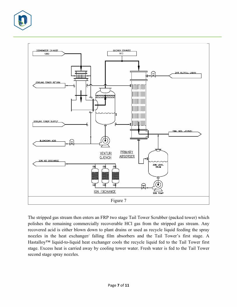
The acid gas leaves the HRSG / Economizer at a temperature above the acid dewpoint. The acid gas first passes through a venturi scrubber to remove any iron chlorides or other particulate (such as refractory dust) that may form in the upstream equipment and can discolor the recovered acid downstream (Figure 7). The scrubber’s acid blowdown stream is directed to plant drains.
The acid gas then enters a block-type graphite heat exchanger, or falling film condensing (absorbing) heat exchanger, which condense the acid gas and recover 33% HCl. The liquid acid condensate from each heat exchanger is collected by gravity in a dedicated FRP tank. Transfer pumps move the recovered product to plant storage or further processing sites. Heat of condensation is carried away from the heat exchangers / absorbers by cooling tower water. 99% of the HCl condensation occurs in the absorbing heat exchangers. The falling film is generated from recycle liquid from the Tail Tower drain.
Page7of11
Figure 7
The stripped gas stream then enters an FRP two stage Tail Tower Scrubber (packed tower) which polishes the remaining commercially recoverable HCl gas from the stripped gas stream. Any recovered acid is either blown down to plant drains or used as recycle liquid feeding the spray nozzles in the heat exchanger/ falling film absorbers and the Tail Tower’s first stage. A Hastalloy™ liquid-to-liquid heat exchanger cools the recycle liquid fed to the Tail Tower first stage. Excess heat is carried away by cooling tower water. Fresh water is fed to the Tail Tower second stage spray nozzles.
Page8of11
Figure 8
Air Pollution Control Stage
After product recovery, the stripped gas stream contains potential air pollutants which must be removed prior to final discharge of the stripped gas stream to atmosphere. At this point, the gas stream contains water, nitrogen, carbon monoxide and traces of chlorine and hydrogen chloride.
After leaving the Tail Tower, the HCl stripped gas enters the 2nd booster blower, which discharges into the Caustic Tower Scrubber (packed tower) where any remnants of HCl are removed (99+% removal efficiency). A 10% NaOH solution is added to the caustic scrubber to react with the remnants of the HCl in the gas stream. A liquid blowdown stream is discharged to plant drains. A Hastalloy liquid-to-liquid heat exchanger removes the heat of reaction from the caustic scrubber recirculation loop. Excess heat is carried away by cooling tower water.
After leaving the Caustic Tower Scrubber, the HCl stripped and oxygen deficient gas stream splits and either passes through the active one of two “combustion” blowers on its way towards a
Page9of11
downstream caustic tower scrubber and catalytic oxidizer or it passes through the active one of two recycle blowers on its way back to the upstream synthesis burner.
The combustion blower inlet duct also connects to a source of fresh air needed to provide oxygen for the catalytic oxidizer during its pre-startup purge cycle or during normal operation. (Note: Now that all commercially recoverable chlorine and HCl has been removed from the gas stream, it is now possible to admit oxygen to the gas stream).
The catalytic oxidizer employs a bed of manganese-oxide catalyst and a 304 stainless steel air-to-air heat exchanger to oxidize contaminants in the stripped gas stream at a reaction temperature of 315-427oC. Organic compounds and carbon monoxide are oxidized to carbon dioxide and/or water vapor; halogens convert to HCl. The oxidizer employs the heat exchanger and a natural gas burner to raise the stripped gas and air mix temperature to the necessary reaction temperature for 99% destruction / reduction efficiency (DRE). Oxidized gases are discharged to atmosphere via a 60 ft tall exhaust stack at approximately 204oC. Supervisory Controls A Programmable Logic Controller (PLC) performs all control, startup, operation, shutdown, and alarming functions of the system. The PLC will incorporate an uninterruptible power supply (UPS) to ensure uninterrupted continuous control and monitoring of the system. The PLC communicates directly with three Input/Output (I/O) racks each located in its own separate control panel containing an operator interface display. Each individual control panel provides the relevant control functions under its area of control. The areas of control are: HCL Reactor/HRSG and Economizer, Product Recovery Area and Pollution Control Area. This arrangement provides reliable system control as the PLC communicates directly with the I/O racks and the redundant PLC with UPS will provide ‘hot-backup’ in the case of a PLC malfunction.
Hazards and Operability Review NESTEC is aware that the each plant and application is unique. Several stages of HCl plant employ equipment which is highly sensitive to sudden changes in temperature that may be occasioned by power interruptions. Nestec expects that a complete and jointly conducted Hazards and Operability review will be undertaken by Nestec and the end user prior to the commencement of final design of the equipment. This review is expected to result in changes
Page10of11
and enhancements to the basic process flow and instrumentation and piping diagrams and the final equipment supply scope. Revisions to equipment scope and cost are likely to result. CONCLUSIONS High purity HCl can be produced using sources other than traditional hydrogen. Product HCl acid was tested for the following components:
Additionally, product HCl acid was tested for 31 organochlorine compounds. “Non-detect” levels of these compounds were observed in the product acid.