2
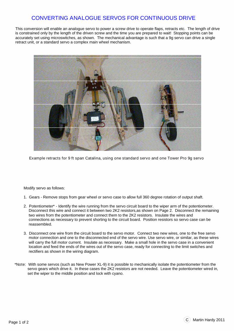
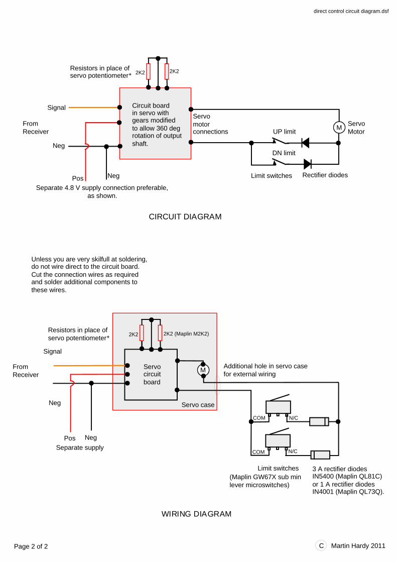
Modify servo as follows: 1. Gears - Remove stops from gear wheel or servo case to allow full 360 degree rotation of output shaft. 2. Potentiometer * - Identify the wire running from the servo circuit board to the wiper arm of the potentiometer. Disconnect this wire and connect it between two 2K2 resistors,as shown on Page 2. Disconnect the remaining two wires from the potentiometer and connect them to the 2K2 resistors. Insulate the wires and connections as necessary to prevent shorting to the circuit board. Position resistors so servo case can be reassembled. 3. Disconnect one wire from the circuit board to the servo motor. Connect two new wires, one to the free servo motor connection and one to the disconnected end of the servo wire. Use servo wire, or similar, as these wires will carry the full motor current. Insulate as necessary. Make a small hole in the servo case in a convenient location and feed the ends of the wires out of the servo case, ready for connecting to the limit switches and rectifiers as shown in the wiring diagram. *Note: With some servos (such as New Power XL-9) it is possible to mechanically isolate the potentiometer from the servo gears which drive it. In these cases the 2K2 resistors are not needed. Leave the potentiometer wired in, set the wiper to the middle position and lock with cyano. CONVERTING ANALOGUE SERVOS FOR CONTINUOUS DRIVE This conversion will enable an analogue servo to power a screw drive to operate flaps, retracts etc. The length of drive is constrained only by the length of the driven screw and the time you are prepared to wait! Stopping points can be accurately set using microswitches, as shown. The mechanical advantage is such that a 9g servo can drive a single retract unit, or a standard servo a complex main wheel mechanism. Example retracts for 9 ft span Catalina, using one standard servo and one Tower Pro 9g servo Page 1 of 2 C Martin Hardy 2011