INSTALLATION GUIDE LIB-CP-REA-03-01 Rev. 11 Conveyor Belt Cleaning System 520 9th Street • Gwinn, MI 49841 • Phone: 800.991.2746 Fax: 906.226.9779 www.argonics.com ARGONICS ENGINEERED POLYURETHANE ™ ERASER ™
Transcript
INSTALLATION GUIDE LIB-CP-REA-03-01 Rev. 11
Conveyor Belt Cleaning System
520 9th Street • Gwinn, MI 49841 • Phone: 800.991.2746 Fax: 906.226.9779www.argonics.com
ARGONICSENGINEERED POLYURETHANE
™
ERASER™
Page 2
I WARNINGAlways obey all applicable safety rules.
Be sure all power to the conveyor has been disconnected and controls are locked out.
ERASER™ Conveyor Belt Cleaning System
- Tape measure - Welder or Drill- Cutting Torch or Hole Saw (31∕2") - 1∕2" End Wrench- Level - 3∕4" End Wrench- Scribe or Chalk - 1" End Wrench or Crescent Wrench
Installation Tools Required
Bolts, lock washers and nuts for mounting are not supplied
* Systems 46" and above come standard with dual tensioners and require double of each of the noted parts.
Safe Torque Ratchet System - Assembly Breakdown
Number Part Number Quantity Description1 CP-AR-”XX”A 1 Mainframe2 CP-RE-”XX”-G83 1 Raptor Blade3 CP-AR-30R 2 Standard Ratchet Mounting Spool4 CP-AR-23-RT-B93 2 Standard Inner Snap Seal5 CP-AR-12B or 2 Stub End CP-AR-22B 2 Extended Stub End6 CP-AR-52B-Y83 2 Standard Dust Cap7* CP-AR-41F 1 Standard Ratchet Spool Washer8* CP-AR-98407A156 2 Retaining Ring9* CP-AR-22C-G83 1 Standard Inner Ratchet Catch10* CP-AR-32C-G83 1 Standard Outer Ratchet Catch11* CP-AR-1-1375-E-B93 or 1 1” Perma-Torque Tensioner CP-AR-1-2075-E-B93 1 1” Extended Perma-Torque Tensioner12 CP-AR-41F-ST 1 Std. Rat. Spool Washer - Single Tensioner13 BOLT-0.38X1.75NC-ZC 2 Bolt, .375”-16 NC, Zinc-Plated 1.75” Long14 NUT-016 2 Nut, .375”-16NC, Zinc-Plated15 WASH-0.38-F-SAE-ZINC 4 Washer, SAE .375”, Zinc-Plated16 CP-AR-512540 2 Bolt, .5”-13 NC, Zinc-Plated 1.25” Long17 CP-AR-5150S 4 Stainless Hex Head Set Screw 1/2” x 1-1/2”18 CP-AR-5125S 2 Stainless Hex Head Set Screw 1/2” x 1-1/4”19 CP-AR-250 1 Safety Snap Pin 3/8” x 2-1/4”20 CP-AR-305 1 Spring Pin21 CP-AR-LC5-G83 2 Standard Locking Collar22 CP-AR-120105 2 Wire Rope Lanyard; 12” Long, 3/64” Wire
Page 3
INSTALLATIONNote: This Eraser primary belt cleaning system is designed to be used on conveyor pulleys of 16" in diameter and larger. For a pulley smaller than 14" in diameter, we recommend our Micro Eraser for proper cleaning of your conveyor system.
Dimension Table - Table 1
Dia. "A" X Z 16" - 28" 4" 93∕4" (minimum)29" & Larger 3" 93∕4" (minimum)
Step One: Layout
Figure 2
After you have determined the mounting location for your belt cleaning system, align the template (see page 11 of this guide) with your bisected horizontal and vertical lines on the mounting structure wall and transfer the center hole, bolt holes and perimeter of the template to the chute wall using your scribe.
Repeat the layout procedure on the opposite mounting structure.For single tensioner, follow instructions on page 4. For dual tensioner, turn to page 6.
Figure 1
NOTE: Shaded areas in Figures 1 and 1a represent acceptable mounting locations.
ATTENTION: Tip of blade is below horizontal axis.
Step Two: Layout
Figure 1a
NOTE: Z dimension shown at 93∕4". NOTE: Z dimension shown at 16".
Inclined belt mounting position
Page 4
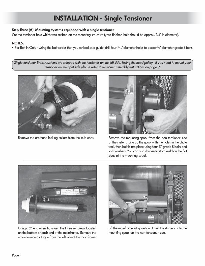
Step Three (A): Mounting systems equipped with a single tensioner
INSTALLATION - Single Tensioner
Cut the tensioner hole which was scribed on the mounting structure (your finished hole should be approx. 31∕2" in diameter).
NOTES:• For Bolt In Only - Using the bolt circles that you scribed as a guide, drill four 13∕16" diameter holes to accept 3∕4" diameter grade 8 bolts.
Remove the urethane locking collars from the stub ends. Remove the mounting spool from the non-tensioner side of the system. Line up the spool with the holes in the chute wall, then bolt it into place using four 3∕4" grade 8 bolts and lock washers. You can also choose to stitch weld on the flat sides of the mounting spool.
Using a 1∕2" end wrench, loosen the three setscrews located on the bottom of each end of the mainframe. Remove the entire tension cartridge from the left side of the mainframe.
Lift the mainframe into position. Insert the stub end into the mounting spool on the non-tensioner side.
Single tensioner Eraser systems are shipped with the tensioner on the left side, facing the head pulley. If you need to mount your tensioner on the right side please refer to tensioner assembly instructions on page 9.
Page 5
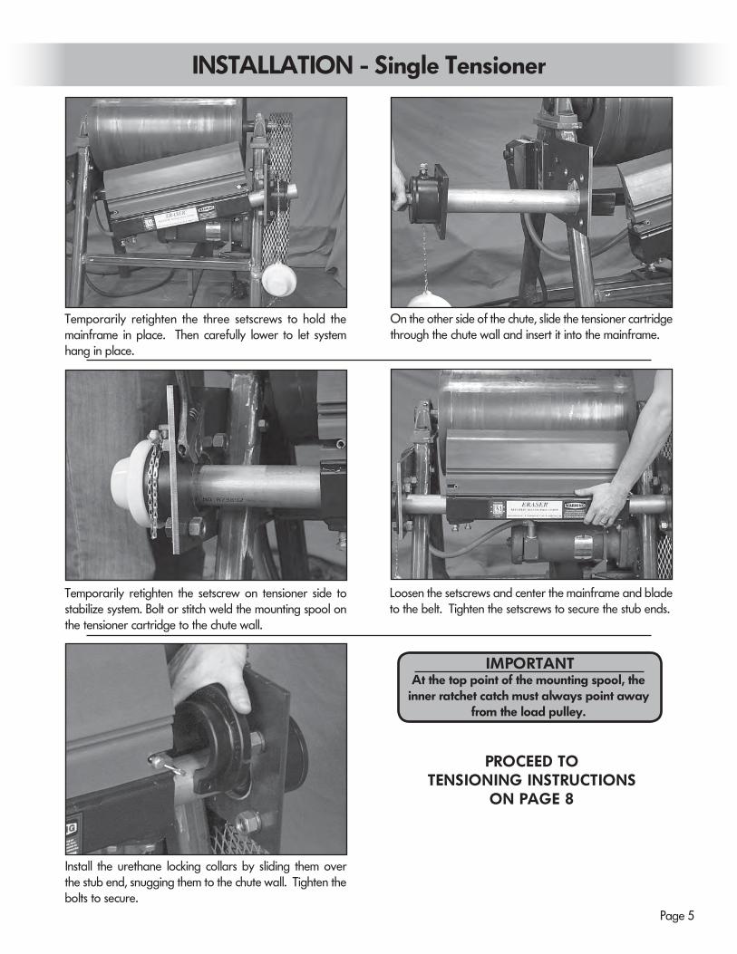
INSTALLATION - Single Tensioner
Temporarily retighten the three setscrews to hold the mainframe in place. Then carefully lower to let system hang in place.
On the other side of the chute, slide the tensioner cartridge through the chute wall and insert it into the mainframe.
Temporarily retighten the setscrew on tensioner side to stabilize system. Bolt or stitch weld the mounting spool on the tensioner cartridge to the chute wall.
Loosen the setscrews and center the mainframe and blade to the belt. Tighten the setscrews to secure the stub ends.
Install the urethane locking collars by sliding them over the stub end, snugging them to the chute wall. Tighten the bolts to secure.
PROCEED TOTENSIONING INSTRUCTIONS
ON PAGE 8
At the top point of the mounting spool, the inner ratchet catch must always point away
from the load pulley.
IMPORTANT
Page 6
Step Three (B): Mounting systems equipped with a dual tensioner Cut the tensioner holes which were scribed on the mounting structure (your finished holes should be approx. 31∕2" in diameter).
NOTES:• For Bolt In Only - Using the bolt circles that you scribed as a guide, drill four 13∕16" diameter holes to accept 3∕4" diameter grade 8 bolts per mounting spool.
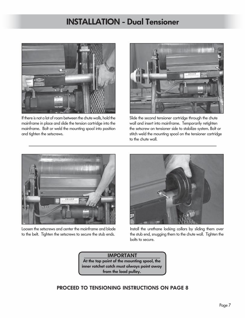
INSTALLATION - Dual Tensioner
Remove the urethane locking collars from the stub ends. Remove both tension cartridges from the mainframe.
If there is room, slide the first tensioner cartridge through the chute wall and line up the mounting spool with the template that was transferred to the chute wall. Now bolt or weld into place.
Lift the mainframe into position. Slide the mainframe onto the cartridge, then temporarily retighten the three setscrews on the tensioner side to stabilize system.
Page 7
INSTALLATION - Dual Tensioner
Loosen the setscrews and center the mainframe and blade to the belt. Tighten the setscrews to secure the stub ends.
Install the urethane locking collars by sliding them over the stub end, snugging them to the chute wall. Tighten the bolts to secure.
PROCEED TO TENSIONING INSTRUCTIONS ON PAGE 8
If there is not a lot of room between the chute walls, hold the mainframe in place and slide the tension cartridge into the mainframe. Bolt or weld the mounting spool into position and tighten the setscrews.
Slide the second tensioner cartridge through the chute wall and insert into mainframe. Temporarily retighten the setscrew on tensioner side to stabilize system. Bolt or stitch weld the mounting spool on the tensioner cartridge to the chute wall.
At the top point of the mounting spool, the inner ratchet catch must always point away
from the load pulley.
IMPORTANT
Page 8
INSTALLATION - TensioningStep Four: Tensioning The Eraser system is equipped with our patented internal Perma-Torque tensioner and our Safe Torque ratchet system. The Perma-Torque is an adjustable elastomeric tensioner. The tensioner may be adjusted from a recommended minimum of 20 foot-pounds of force to a maximum of 80 foot-pounds. Exceeding tensioning of 24 clicks or 480° of rotation could damage the tensioner as well as the Safe Torque ratchet system. Four (4) clicks, or 90° of rotation is recommended for most applications.
To tension, first position the alignment notch on the outer ratchet catch with the mounting spool set screw. Grab the blade and rotate to align the ratchet notch.
When notch is aligned, tighten the setscrew.(Arrow indicates proper notch position.)
Use a 1" socket wrench on the exposed tensioner hex rod and turn the tensioner up and towards the pulley until the blade makes contact with the belt. Start tensioning by counting the clicks until you have reached the desired rotation. Four (4) clicks or 90° of rotation is the factory recommended setting. Repeat the same number of clicks on the opposite side for a dual tensioner system. Re-attach the dust cap(s).
When you need to release tension, just loosen the mounting spool set screw. You will see the outer ratchet rotate as the tension is released.
Installation of your Argonics Eraser belt cleaning system is now complete.Maintenance or re-tensioning should not be required throughout the life of the blade.
Do Not OvertensionOvertensioning will result in increased
blade wear
Releasing TensionGuideline for tensioning
belt cleaning systemsMetric belt
width
Blade width
No. of clicks
Lbs of force
300 10
4 50
Sing
le T
ensio
ner
450 16
600 22
750 28
5 60900 34
1050 40
1200 46
4 50
Dou
ble
Tens
ione
r1400 52
1500 58
1800 70
5 602100 82
2400 94
2800 1086 70
3000 120
Page 9
INSTALLATION - Left to Right Tensioner ConversionTensioner Conversion Instructions To mount a single tensioned Eraser system with the tensioner on the right side instead of the left side, you will need to switch the entire tensioning spool to the other side of the mainframe, as well as the direction that the ratchet gears are oriented. It is recom-mended that you perform this conversion on the ground before the system is mounted.
Flip both the inner ratchet and outer catch so the gear teeth are pointed in the opposite direction and slide both back onto the hex rod.
Align the outer catch notch to the top of the mounting spool, tighten the set screw and then re-insert the retaining clip to the outer groove of the hex rod.
Remove the retainer clip from the hex rod using a flat blade screwdriver. Be sure not to lose the retainer clip.
Your Eraser system comes with the tensioner mounted on the left. You will need to switch the entire mounting spool assembly to the right side of the mainframe.
Unscrew the setscrew at the top of the mounting spool and remove both the inner ratchet and outer catch. Make sure you note what direction the gears are pointing.
Continue following the installation instructionslocated on page 4.
At the top point of the mounting spool, the inner ratchet catch must always point away
from your conveyor load pulley.
IMPORTANT
Page 10
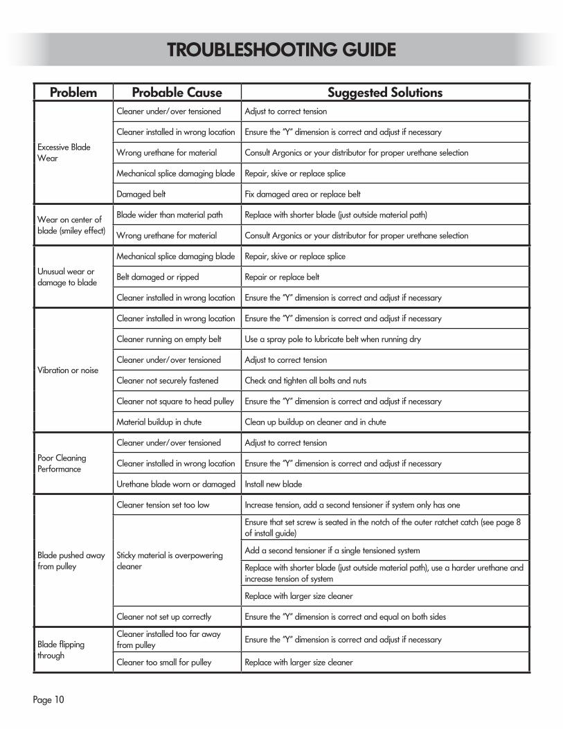
TROUBLESHOOTING GUIDE
Problem Probable Cause Suggested Solutions
Excessive Blade Wear
Cleaner under/over tensioned Adjust to correct tension
Cleaner installed in wrong location Ensure the "Y" dimension is correct and adjust if necessary
Wrong urethane for material Consult Argonics or your distributor for proper urethane selection
Mechanical splice damaging blade Repair, skive or replace splice
Damaged belt Fix damaged area or replace belt
Wear on center of blade (smiley effect)
Blade wider than material path Replace with shorter blade (just outside material path)
Wrong urethane for material Consult Argonics or your distributor for proper urethane selection
Unusual wear or damage to blade
Mechanical splice damaging blade Repair, skive or replace splice
Belt damaged or ripped Repair or replace belt
Cleaner installed in wrong location Ensure the "Y" dimension is correct and adjust if necessary
Vibration or noise
Cleaner installed in wrong location Ensure the "Y" dimension is correct and adjust if necessary
Cleaner running on empty belt Use a spray pole to lubricate belt when running dry
Cleaner under/over tensioned Adjust to correct tension
Cleaner not securely fastened Check and tighten all bolts and nuts
Cleaner not square to head pulley Ensure the "Y" dimension is correct and adjust if necessary
Material buildup in chute Clean up buildup on cleaner and in chute
Poor Cleaning Performance
Cleaner under/over tensioned Adjust to correct tension
Cleaner installed in wrong location Ensure the "Y" dimension is correct and adjust if necessary
Urethane blade worn or damaged Install new blade
Blade pushed away from pulley
Cleaner tension set too low Increase tension, add a second tensioner if system only has one
Sticky material is overpowering cleaner
Ensure that set screw is seated in the notch of the outer ratchet catch (see page 8 of install guide)
Add a second tensioner if a single tensioned system
Replace with shorter blade (just outside material path), use a harder urethane and increase tension of system
Replace with larger size cleaner
Cleaner not set up correctly Ensure the "Y" dimension is correct and equal on both sides
Blade flipping through
Cleaner installed too far away from pulley
Ensure the "Y" dimension is correct and adjust if necessary
Cleaner too small for pulley Replace with larger size cleaner
Page 11
Transfer the drawing below to cardboard, and use as yourmounting spool template.
MOUNTING TEMPLATE
Template is drawn to actual size.
Argonics, Inc. • 520 9th St. • Gwinn, MI 49841 USA • Phone: 906.226.9747 800.991.2746 Fax: 906.226.9779Eraser™, Raptor™, Safe Torque™ and Perma-Torque™ are trademarks of Argonics, Inc. Gwinn, MI. USA
Argonics Conveyor Belt Cleaning Systems are protected by one or more of the following patents: 5,979,638; 6,056,112; 7,441,647.www.argonics.com
OTHER QUALITY PRODUCTS FROM ARGONICS
THE MOST RELIABLE AND COST-EFFECTIVE SKIRTING AVAILABLE
MADE WITH KRYPTANE® POLYURETHANEArgonics formulates unique proprietary Kryptane polyurethane materials tailored to meet the demands of your wear application, whether it be sliding or impact abrasion, sticking or corrosion.
BENEFITS OF ARGONICS POLYURETHANE SKIRTING:
• 6 - 10 times the wear life over rubber
• 60% lower coefficient of friction compared to rubber, which reduces drag on conveyor motor
• Will not groove your conveyor belt when installed correctly
FOLD-N-SEAL™
If you’re looking for a quality multi-sealing conveyor skirting solution that isn’t hard on your budget, look no further: Fold-n-Seal is your answer.
Fold-n-Seal gives you the best of both worlds: material and dust containment in one unique solution. The primary seal keeps the material where it should be – on the belt. The secondary seal keeps dust and particulate material under control.
SNAP-LOC™ DUST SEAL
Snap-Loc is the gold standard for dust containment skirting. This straight-forward, no-nonsense design for dust control snaps into standard unistrut railing that can be bolted or welded into place.
Snap-Loc Dust Seal is engineered to create a perfect seal that follows the contours and low spots of the belt between trough rollers. No additional adjustments are needed for the life of the seal, saving you in both cost and hours of maintenance.
LOAD ZONE CONTAINMENT SKIRTINGDesigned to do one thing and do it well: contain material at the transfer points on your belt line. The extra-rugged reinforced design with 1∕4” steel means that our Containment Skirting is extremely effective in reducing spillage, resulting in reduced clean-up labor.
Containment skirting is available with either a flat or 20° beveled edge, and in 60” and 96” lengths. Varying heights and thicknesses available.