INSTALLATION GUIDE LIB-CP-ESG-03-01 Rev. 4 Conveyor Belt Cleaning System SUPER-G ™ 520 9th Street • Gwinn, MI 49841 • Phone: 800.991.2746 Fax: 906.226.9779 www.argonics.com ARGONICS ENGINEERED POLYURETHANE ™
Transcript
INSTALLATION GUIDE LIB-CP-ESG-03-01 Rev. 4
Conveyor Belt Cleaning System
SUPER-G™
520 9th Street • Gwinn, MI 49841 • Phone: 800.991.2746 Fax: 906.226.9779www.argonics.com
ARGONICSENGINEERED POLYURETHANE
™
Page 2
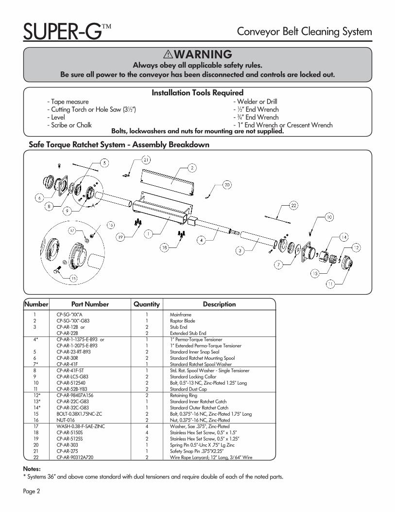
Notes:* Systems 36" and above come standard with dual tensioners and require double of each of the noted parts.
Number Part Number Quantity Description1 CP-SG-”XX”A 1 Mainframe2 CP-SG-”XX”-G83 1 Raptor Blade 3 CP-AR-12B or 2 Stub End CP-AR-22B 2 Extended Stub End4* CP-AR-1-1375-E-B93 or 1 1” Perma-Torque Tensioner CP-AR-1-2075-E-B93 1 1” Extended Perma-Torque Tensioner5 CP-AR-23-RT-B93 2 Standard Inner Snap Seal6 CP-AR-30R 2 Standard Ratchet Mounting Spool7* CP-AR-41F 1 Standard Ratchet Spool Washer8 CP-AR-41F-ST 1 Std. Rat. Spool Washer - Single Tensioner9 CP-AR-LC5-G83 2 Standard Locking Collar10 CP-AR-512540 2 Bolt, 0.5”-13 NC, Zinc-Plated 1.25” Long11 CP-AR-52B-Y83 2 Standard Dust Cap12* CP-AR-98407A156 2 Retaining Ring13* CP-AR-22C-G83 1 Standard Inner Ratchet Catch14* CP-AR-32C-G83 1 Standard Outer Ratchet Catch15 BOLT-0.38X1.75NC-ZC 2 Bolt, 0.375”-16 NC, Zinc-Plated 1.75” Long16 NUT-016 2 Nut, 0.375”-16 NC, Zinc-Plated17 WASH-0.38-F-SAE-ZINC 4 Washer, Sae .375”, Zinc-Plated18 CP-AR-5150S 4 Stainless Hex Set Screw, 0.5” x 1.5”19 CP-AR-5125S 2 Stainless Hex Set Screw, 0.5” x 1.25”20 CP-AR-303 1 Spring Pin 0.5”-Unc X .75” Lg Zinc21 CP-AR-275 1 Safety Snap Pin .375”X2.25”22 CP-AR-90312A720 2 Wire Rope Lanyard; 12” Long, 3/64” Wire
- Tape measure - Welder or Drill- Cutting Torch or Hole Saw (31∕2") - 1∕2" End Wrench- Level - 3∕4” End Wrench- Scribe or Chalk - 1” End Wrench or Crescent Wrench
Installation Tools Required
Bolts, lockwashers and nuts for mounting are not supplied.
Safe Torque Ratchet System - Assembly Breakdown
I WARNINGAlways obey all applicable safety rules.
Be sure all power to the conveyor has been disconnected and controls are locked out.
SUPER-G™ Conveyor Belt Cleaning System
Page 3
Note: This Super-G Secondary belt cleaning system is designed to be used on conveyor pulleys of 14" in diameter and larger.
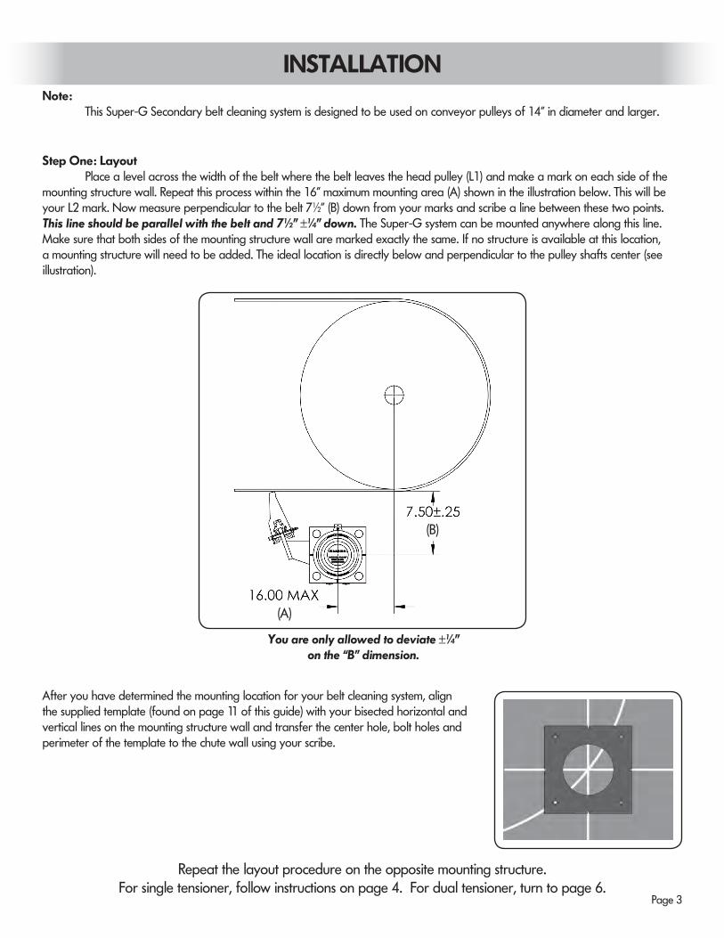
After you have determined the mounting location for your belt cleaning system, align the supplied template (found on page 11 of this guide) with your bisected horizontal and vertical lines on the mounting structure wall and transfer the center hole, bolt holes and perimeter of the template to the chute wall using your scribe.
Step One: Layout Place a level across the width of the belt where the belt leaves the head pulley (L1) and make a mark on each side of the mounting structure wall. Repeat this process within the 16" maximum mounting area (A) shown in the illustration below. This will be your L2 mark. Now measure perpendicular to the belt 71∕2" (B) down from your marks and scribe a line between these two points. This line should be parallel with the belt and 71∕2" ±1∕4" down. The Super-G system can be mounted anywhere along this line. Make sure that both sides of the mounting structure wall are marked exactly the same. If no structure is available at this location, a mounting structure will need to be added. The ideal location is directly below and perpendicular to the pulley shafts center (see illustration).
You are only allowed to deviate ±1∕4"on the “B” dimension.
Repeat the layout procedure on the opposite mounting structure.For single tensioner, follow instructions on page 4. For dual tensioner, turn to page 6.
INSTALLATION
(A)
(B)
Page 4
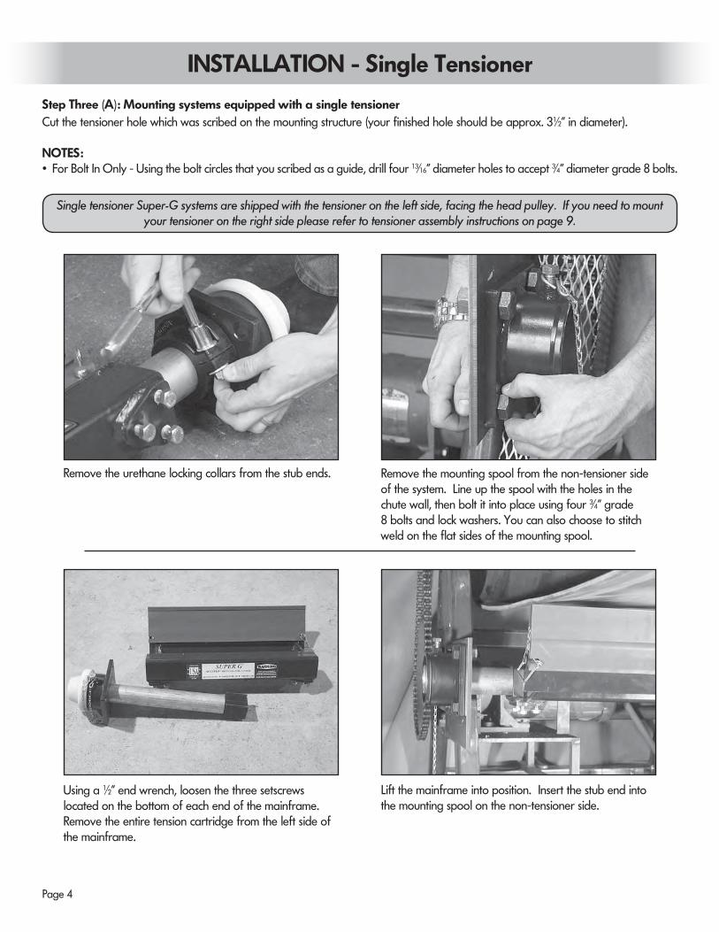
Remove the urethane locking collars from the stub ends. Remove the mounting spool from the non-tensioner side of the system. Line up the spool with the holes in the chute wall, then bolt it into place using four 3∕4" grade 8 bolts and lock washers. You can also choose to stitch weld on the flat sides of the mounting spool.
Using a 1∕2" end wrench, loosen the three setscrews located on the bottom of each end of the mainframe. Remove the entire tension cartridge from the left side of the mainframe.
Lift the mainframe into position. Insert the stub end into the mounting spool on the non-tensioner side.
Step Three (A): Mounting systems equipped with a single tensioner
INSTALLATION - Single Tensioner
Cut the tensioner hole which was scribed on the mounting structure (your finished hole should be approx. 31∕2" in diameter).
NOTES:• For Bolt In Only - Using the bolt circles that you scribed as a guide, drill four 13∕16" diameter holes to accept 3∕4" diameter grade 8 bolts.
Single tensioner Super-G systems are shipped with the tensioner on the left side, facing the head pulley. If you need to mount your tensioner on the right side please refer to tensioner assembly instructions on page 9.
Page 5
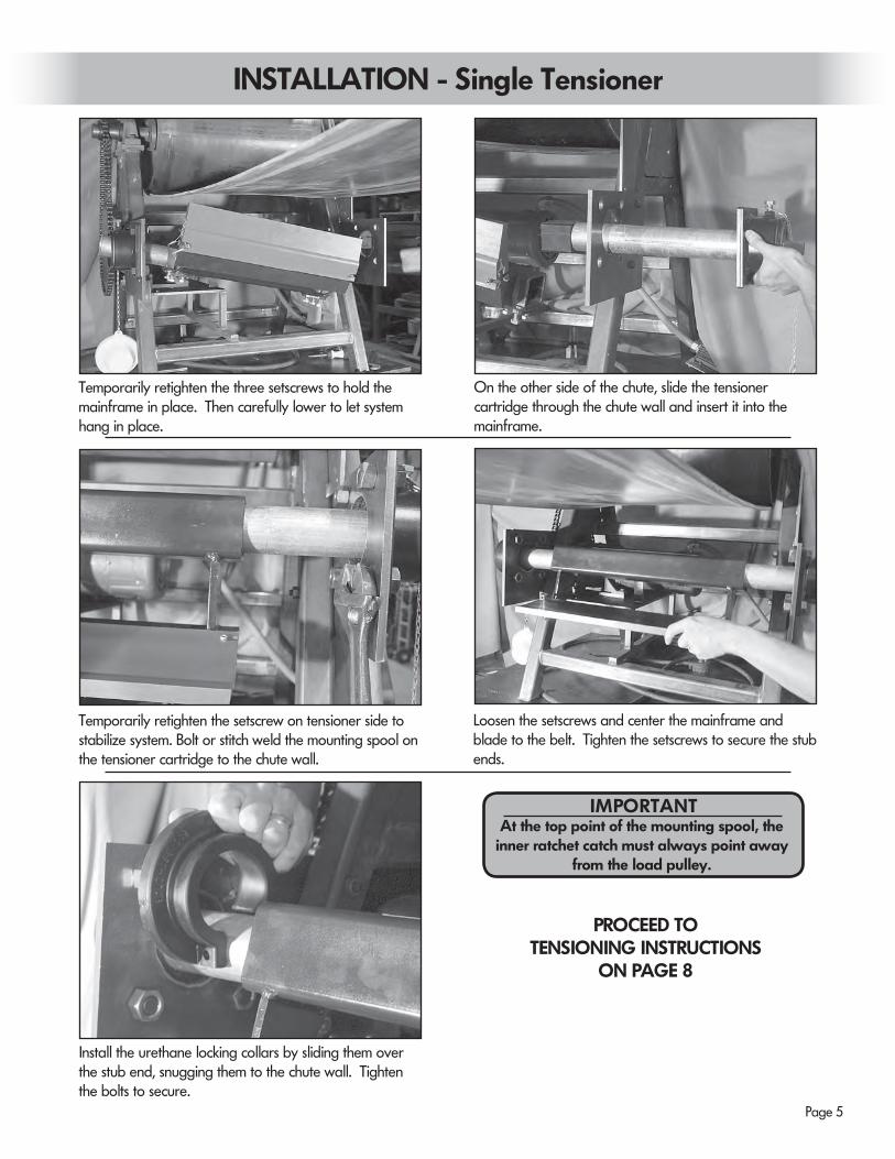
Temporarily retighten the three setscrews to hold the mainframe in place. Then carefully lower to let system hang in place.
On the other side of the chute, slide the tensioner cartridge through the chute wall and insert it into the mainframe.
Temporarily retighten the setscrew on tensioner side to stabilize system. Bolt or stitch weld the mounting spool on the tensioner cartridge to the chute wall.
Loosen the setscrews and center the mainframe and blade to the belt. Tighten the setscrews to secure the stub ends.
Install the urethane locking collars by sliding them over the stub end, snugging them to the chute wall. Tighten the bolts to secure.
PROCEED TOTENSIONING INSTRUCTIONS
ON PAGE 8
INSTALLATION - Single Tensioner
At the top point of the mounting spool, the inner ratchet catch must always point away
from the load pulley.
IMPORTANT
Page 6
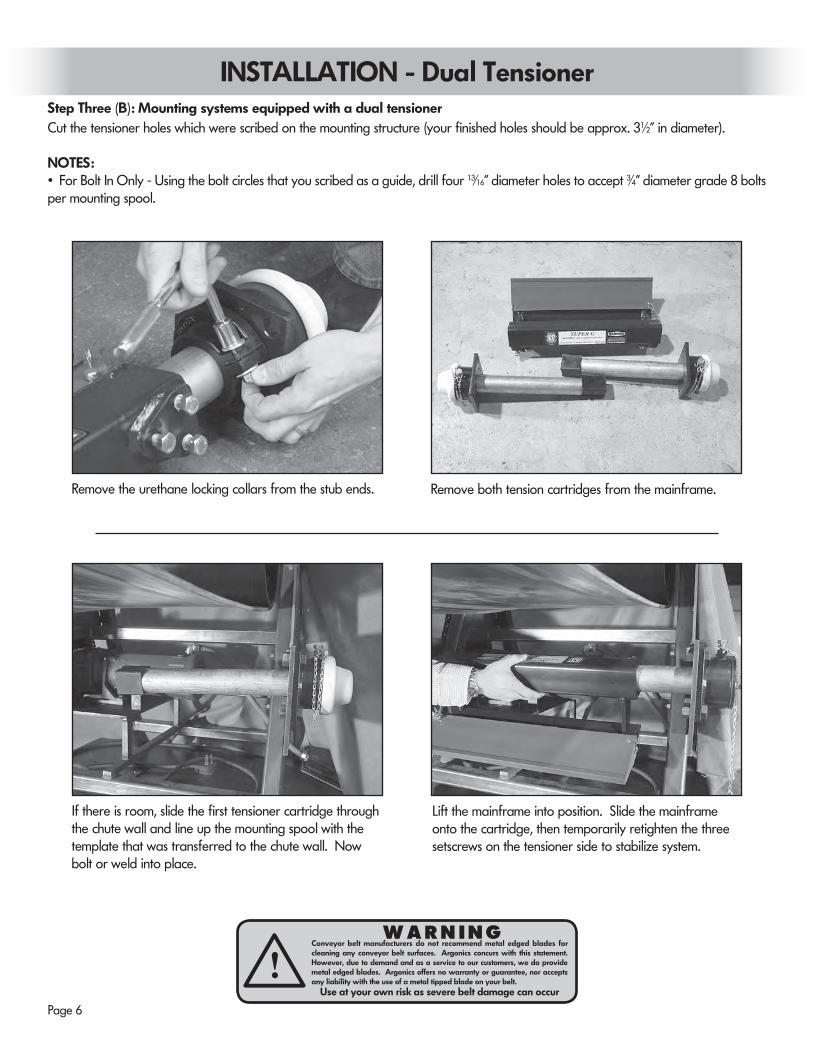
Remove the urethane locking collars from the stub ends. Remove both tension cartridges from the mainframe.
If there is room, slide the first tensioner cartridge through the chute wall and line up the mounting spool with the template that was transferred to the chute wall. Now bolt or weld into place.
Lift the mainframe into position. Slide the mainframe onto the cartridge, then temporarily retighten the three setscrews on the tensioner side to stabilize system.
Step Three (B): Mounting systems equipped with a dual tensioner Cut the tensioner holes which were scribed on the mounting structure (your finished holes should be approx. 31∕2" in diameter).
NOTES:• For Bolt In Only - Using the bolt circles that you scribed as a guide, drill four 13∕16" diameter holes to accept 3∕4" diameter grade 8 bolts per mounting spool.
INSTALLATION - Dual Tensioner
W A R N I N GConveyor belt manufacturers do not recommend metal edged blades for cleaning any conveyor belt surfaces. Argonics concurs with this statement. However, due to demand and as a service to our customers, we do provide metal edged blades. Argonics offers no warranty or guarantee, nor accepts any liability with the use of a metal tipped blade on your belt.
Use at your own risk as severe belt damage can occuri
Page 7
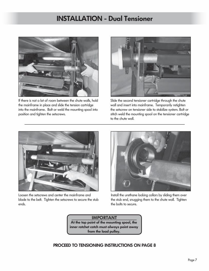
Loosen the setscrews and center the mainframe and blade to the belt. Tighten the setscrews to secure the stub ends.
Install the urethane locking collars by sliding them over the stub end, snugging them to the chute wall. Tighten the bolts to secure.
PROCEED TO TENSIONING INSTRUCTIONS ON PAGE 8
If there is not a lot of room between the chute walls, hold the mainframe in place and slide the tension cartridge into the mainframe. Bolt or weld the mounting spool into position and tighten the setscrews.
Slide the second tensioner cartridge through the chute wall and insert into mainframe. Temporarily retighten the setscrew on tensioner side to stabilize system. Bolt or stitch weld the mounting spool on the tensioner cartridge to the chute wall.
INSTALLATION - Dual Tensioner
At the top point of the mounting spool, the inner ratchet catch must always point away
from the load pulley.
IMPORTANT
Page 8
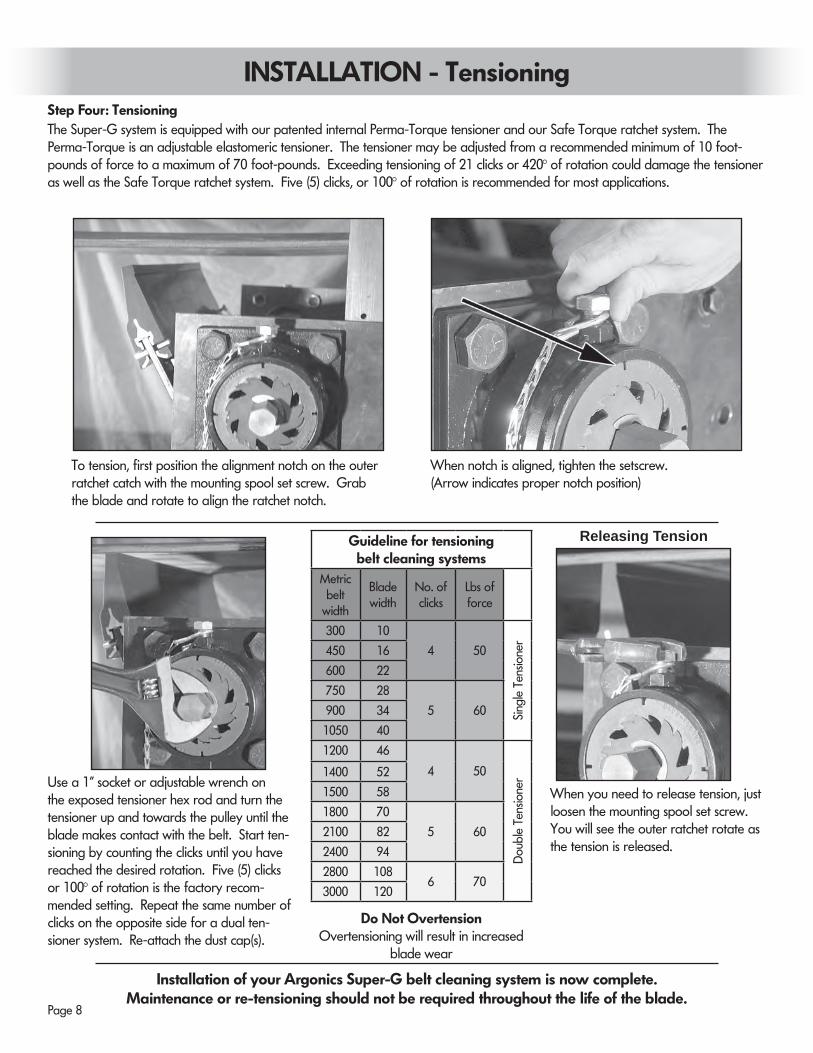
Step Four: Tensioning The Super-G system is equipped with our patented internal Perma-Torque tensioner and our Safe Torque ratchet system. The Perma-Torque is an adjustable elastomeric tensioner. The tensioner may be adjusted from a recommended minimum of 10 foot-pounds of force to a maximum of 70 foot-pounds. Exceeding tensioning of 21 clicks or 420° of rotation could damage the tensioner as well as the Safe Torque ratchet system. Five (5) clicks, or 100° of rotation is recommended for most applications.
To tension, first position the alignment notch on the outer ratchet catch with the mounting spool set screw. Grab the blade and rotate to align the ratchet notch.
When notch is aligned, tighten the setscrew.(Arrow indicates proper notch position)
Use a 1" socket or adjustable wrench on the exposed tensioner hex rod and turn the tensioner up and towards the pulley until the blade makes contact with the belt. Start ten-sioning by counting the clicks until you have reached the desired rotation. Five (5) clicks or 100° of rotation is the factory recom-mended setting. Repeat the same number of clicks on the opposite side for a dual ten-sioner system. Re-attach the dust cap(s).
When you need to release tension, just loosen the mounting spool set screw. You will see the outer ratchet rotate as the tension is released.
Installation of your Argonics Super-G belt cleaning system is now complete.Maintenance or re-tensioning should not be required throughout the life of the blade.
Releasing Tension
INSTALLATION - Tensioning
Do Not OvertensionOvertensioning will result in increased
blade wear
Guideline for tensioning belt cleaning systems
Metric belt
width
Blade width
No. of clicks
Lbs of force
300 10
4 50
Sing
le T
ensio
ner
450 16
600 22
750 28
5 60900 34
1050 40
1200 46
4 50
Dou
ble
Tens
ione
r1400 52
1500 58
1800 70
5 602100 82
2400 94
2800 1086 70
3000 120
Page 9
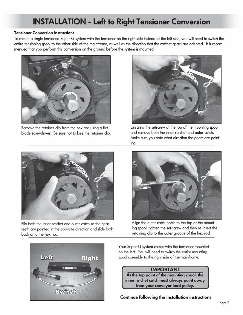
Tensioner Conversion Instructions To mount a single tensioned Super-G system with the tensioner on the right side instead of the left side, you will need to switch the entire tensioning spool to the other side of the mainframe, as well as the direction that the ratchet gears are oriented. It is recom-mended that you perform this conversion on the ground before the system is mounted.
Flip both the inner ratchet and outer catch so the gear teeth are pointed in the opposite direction and slide both back onto the hex rod.
Align the outer catch notch to the top of the mount-ing spool, tighten the set screw and then re-insert the retaining clip to the outer groove of the hex rod.
Remove the retainer clip from the hex rod using a flat blade screwdriver. Be sure not to lose the retainer clip.
Your Super-G system comes with the tensioner mounted on the left. You will need to switch the entire mounting spool assembly to the right side of the mainframe.
Unscrew the setscrew at the top of the mounting spool and remove both the inner ratchet and outer catch. Make sure you note what direction the gears are point-ing.
Continue following the installation instructions
INSTALLATION - Left to Right Tensioner Conversion
At the top point of the mounting spool, the inner ratchet catch must always point away
from your conveyor load pulley.
IMPORTANT
Page 10
REPLACING TUNGSTEN BLADES
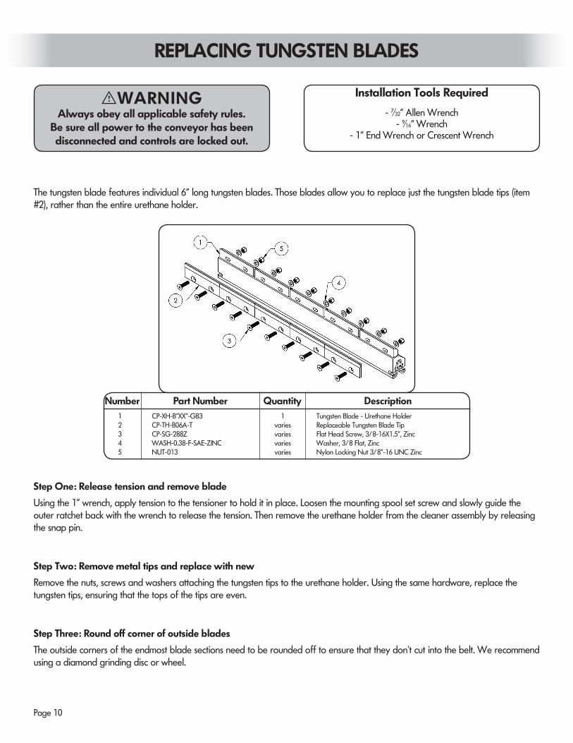
The tungsten blade features individual 6” long tungsten blades. Those blades allow you to replace just the tungsten blade tips (item #2), rather than the entire urethane holder.
Step Two: Remove metal tips and replace with new
Remove the nuts, screws and washers attaching the tungsten tips to the urethane holder. Using the same hardware, replace the tungsten tips, ensuring that the tops of the tips are even.
Step One: Release tension and remove blade
Using the 1” wrench, apply tension to the tensioner to hold it in place. Loosen the mounting spool set screw and slowly guide the outer ratchet back with the wrench to release the tension. Then remove the urethane holder from the cleaner assembly by releasing the snap pin.
Step Three: Round off corner of outside blades
The outside corners of the endmost blade sections need to be rounded off to ensure that they don’t cut into the belt. We recommend using a diamond grinding disc or wheel.
Number Part Number Quantity Description1 CP-XH-B”XX”-G83 1 Tungsten Blade - Urethane Holder2 CP-TH-B06A-T varies Replaceable Tungsten Blade Tip3 CP-SG-288Z varies Flat Head Screw, 3/8-16X1.5”, Zinc4 WASH-0.38-F-SAE-ZINC varies Washer, 3/8 Flat, Zinc 5 NUT-013 varies Nylon Locking Nut 3/8”-16 UNC Zinc
- 7∕32“ Allen Wrench- 9∕16“ Wrench
- 1” End Wrench or Crescent Wrench
Installation Tools RequiredI WARNINGAlways obey all applicable safety rules.
Be sure all power to the conveyor has been disconnected and controls are locked out.
Page 11
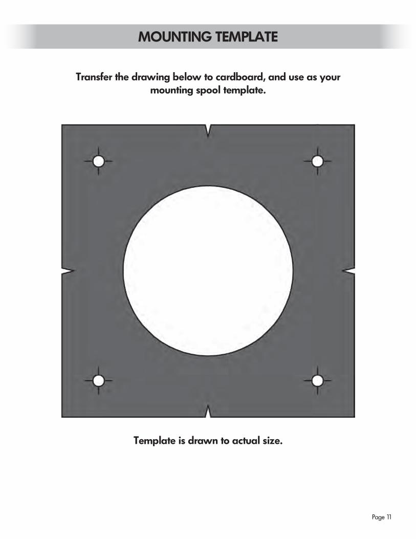
Transfer the drawing below to cardboard, and use as yourmounting spool template.
Template is drawn to actual size.
MOUNTING TEMPLATE
Page 12
Argonics, Inc. • 520 9th St. • Gwinn, MI 49841 USA • Phone: 906.226.9747 800.991.2746 Fax: 906.226.9779Super-G™, Raptor™, Safe Torque™ and Perma-Torque™ are trademarks of Argonics, Inc. Gwinn, MI. USA
Argonics Conveyor Belt Cleaning Systems are protected by one or more of the following patents: 5,979,638; 6,056,112; 7,441,647.www.argonics.com
OTHER QUALITY PRODUCTS FROM ARGONICS
THE MOST RELIABLE AND COST-EFFECTIVE SKIRTING AVAILABLE
MADE WITH KRYPTANE® POLYURETHANEArgonics formulates unique proprietary Kryptane polyurethane materials tailored to meet the demands of your wear application, whether it be sliding or impact abrasion, sticking or corrosion.
BENEFITS OF ARGONICS POLYURETHANE SKIRTING:
• 6 - 10 times the wear life over rubber
• 60% lower coefficient of friction compared to rubber, which reduces drag on conveyor motor
• Will not groove your conveyor belt when installed correctly
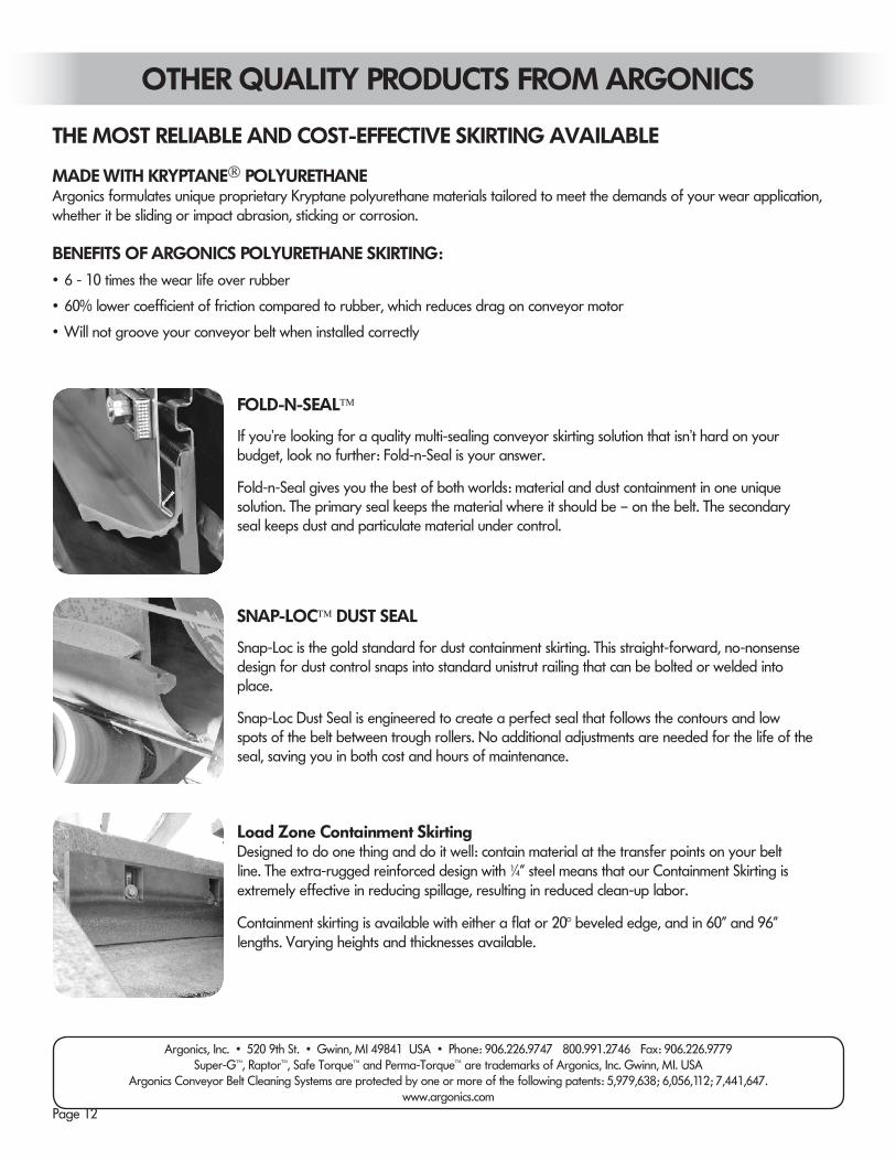
FOLD-N-SEAL™
If you’re looking for a quality multi-sealing conveyor skirting solution that isn’t hard on your budget, look no further: Fold-n-Seal is your answer.
Fold-n-Seal gives you the best of both worlds: material and dust containment in one unique solution. The primary seal keeps the material where it should be – on the belt. The secondary seal keeps dust and particulate material under control.
SNAP-LOC™ DUST SEAL
Snap-Loc is the gold standard for dust containment skirting. This straight-forward, no-nonsense design for dust control snaps into standard unistrut railing that can be bolted or welded into place.
Snap-Loc Dust Seal is engineered to create a perfect seal that follows the contours and low spots of the belt between trough rollers. No additional adjustments are needed for the life of the seal, saving you in both cost and hours of maintenance.
Load Zone Containment SkirtingDesigned to do one thing and do it well: contain material at the transfer points on your belt line. The extra-rugged reinforced design with 1∕4” steel means that our Containment Skirting is extremely effective in reducing spillage, resulting in reduced clean-up labor.
Containment skirting is available with either a flat or 20° beveled edge, and in 60” and 96” lengths. Varying heights and thicknesses available.


![1 SERIES Belt Conveyor System B090 - Bett Sistemi Srl€¦ · CONVEYOR BELT DEVELOPMENT CALCULATION FORMULA Conveyor belt length = 300 + {[(L-94)-(2• Conveyor belt thick. )]•2}](https://static.documents.pub/doc/80x56/5ad3c4047f8b9a48398b7ae4/1-series-belt-conveyor-system-b090-bett-sistemi-conveyor-belt-development-calculation.jpg)


