1/ PROTECCIÓN DEL MEDIO AMBIENTE — Los materiales utilizados para el embalaje de este aparato son reciclables. Participe en su reciclaje y contribuya así a conservar el medio ambiente tirándolos a los contenedores municipals previstos para ellos. — Su aparato también contiene materiales reciclables, por lo que está marcado con este logotipo que le indica que los aparatos desechados no deben mezclarse con otros residuos. Actuando así, el reciclaje de los aparatos que organiza su fabricante se efectuará en las mejores condiciones posibles, de acuerdo con la directiva europea
2002/96/CE sobre los residuos de equipos eléctricos y electrónicos. Consulte en su ayuntamiento o a su vendedor para conocer dónde se encuentran los puntos de recogida de aparatos desechados más cercanos a su domicilio. — Le damos las gracias por su colaboración en la protección del medio
ambiente.
Atención La instalación está reservada a los instaladores y técnicos cualificados.
Atención Antes de utilizar por primera vez el filtro modular, retire la película protectora.
8
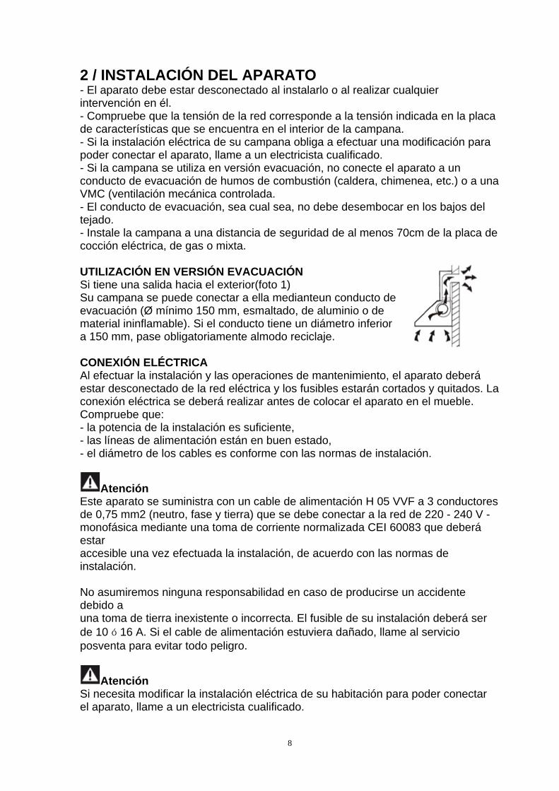
2 / INSTALACIÓN DEL APARATO - El aparato debe estar desconectado al instalarlo o al realizar cualquier intervención en él. - Compruebe que la tensión de la red corresponde a la tensión indicada en la placa de características que se encuentra en el interior de la campana. - Si la instalación eléctrica de su campana obliga a efectuar una modificación para poder conectar el aparato, llame a un electricista cualificado. - Si la campana se utiliza en versión evacuación, no conecte el aparato a un conducto de evacuación de humos de combustión (caldera, chimenea, etc.) o a una VMC (ventilación mecánica controlada. - El conducto de evacuación, sea cual sea, no debe desembocar en los bajos del tejado. - Instale la campana a una distancia de seguridad de al menos 70cm de la placa de cocción eléctrica, de gas o mixta. UTILIZACIÓN EN VERSIÓN EVACUACIÓN Si tiene una salida hacia el exterior(foto 1) Su campana se puede conectar a ella medianteun conducto de evacuación (Ø mínimo 150 mm, esmaltado, de aluminio o de material ininflamable). Si el conducto tiene un diámetro inferior a 150 mm, pase obligatoriamente almodo reciclaje. CONEXIÓN ELÉCTRICA Al efectuar la instalación y las operaciones de mantenimiento, el aparato deberá estar desconectado de la red eléctrica y los fusibles estarán cortados y quitados. La conexión eléctrica se deberá realizar antes de colocar el aparato en el mueble. Compruebe que: - la potencia de la instalación es suficiente, - las líneas de alimentación están en buen estado, - el diámetro de los cables es conforme con las normas de instalación.
Atención Este aparato se suministra con un cable de alimentación H 05 VVF a 3 conductores de 0,75 mm2 (neutro, fase y tierra) que se debe conectar a la red de 220 - 240 V - monofásica mediante una toma de corriente normalizada CEI 60083 que deberá estar accesible una vez efectuada la instalación, de acuerdo con las normas de instalación. No asumiremos ninguna responsabilidad en caso de producirse un accidente debido a una toma de tierra inexistente o incorrecta. El fusible de su instalación deberá ser de 10 ó 16 A. Si el cable de alimentación estuviera dañado, llame al servicio posventa para evitar todo peligro.
Atención Si necesita modificar la instalación eléctrica de su habitación para poder conectar el aparato, llame a un electricista cualificado.
9
Atención Si la campana tiene cualquier anomalía, desconecte el aparato o quite el fusible correspondiente a la línea de conexión del aparato. MONTAJE DE LA CAMPANA EXTRACTORA
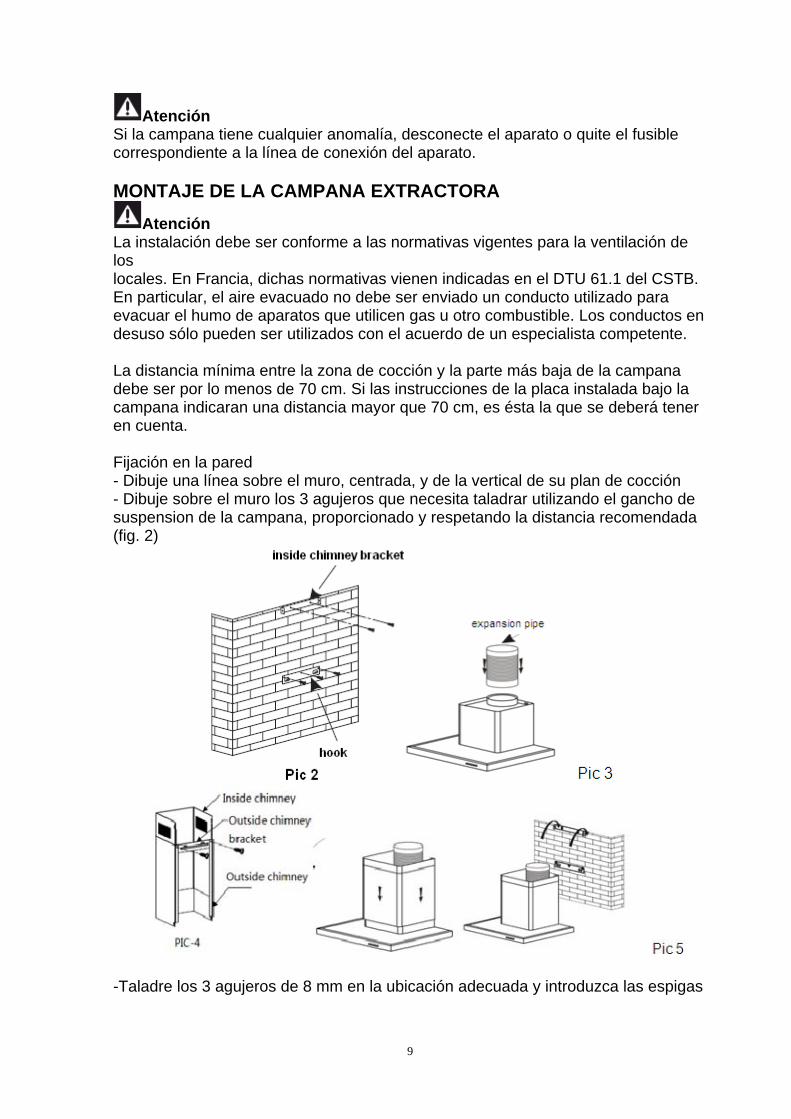
Atención La instalación debe ser conforme a las normativas vigentes para la ventilación de los locales. En Francia, dichas normativas vienen indicadas en el DTU 61.1 del CSTB. En particular, el aire evacuado no debe ser enviado un conducto utilizado para evacuar el humo de aparatos que utilicen gas u otro combustible. Los conductos en desuso sólo pueden ser utilizados con el acuerdo de un especialista competente. La distancia mínima entre la zona de cocción y la parte más baja de la campana debe ser por lo menos de 70 cm. Si las instrucciones de la placa instalada bajo la campana indicaran una distancia mayor que 70 cm, es ésta la que se deberá tener en cuenta. Fijación en la pared - Dibuje una línea sobre el muro, centrada, y de la vertical de su plan de cocción - Dibuje sobre el muro los 3 agujeros que necesita taladrar utilizando el gancho de suspension de la campana, proporcionado y respetando la distancia recomendada (fig. 2)
-Taladre los 3 agujeros de 8 mm en la ubicación adecuada y introduzca las espigas
10
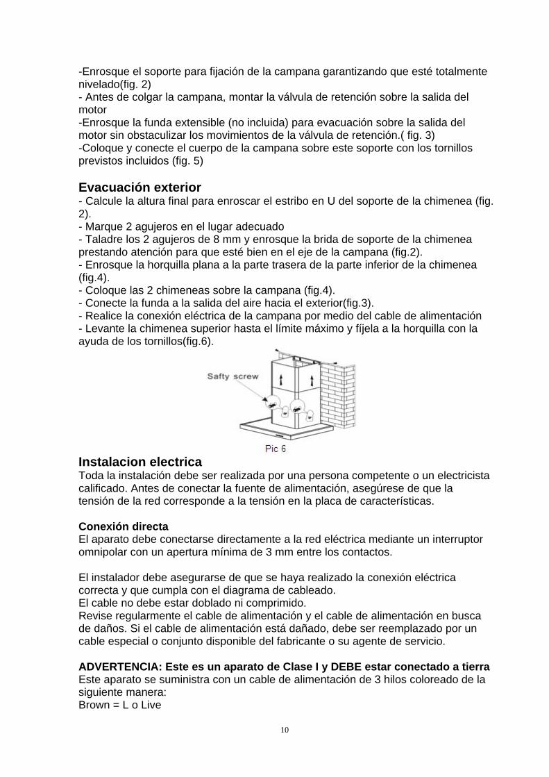
-Enrosque el soporte para fijación de la campana garantizando que esté totalmente nivelado(fig. 2) - Antes de colgar la campana, montar la válvula de retención sobre la salida del motor -Enrosque la funda extensible (no incluida) para evacuación sobre la salida del motor sin obstaculizar los movimientos de la válvula de retención.( fig. 3) -Coloque y conecte el cuerpo de la campana sobre este soporte con los tornillos previstos incluidos (fig. 5) Evacuación exterior - Calcule la altura final para enroscar el estribo en U del soporte de la chimenea (fig. 2). - Marque 2 agujeros en el lugar adecuado - Taladre los 2 agujeros de 8 mm y enrosque la brida de soporte de la chimenea prestando atención para que esté bien en el eje de la campana (fig.2). - Enrosque la horquilla plana a la parte trasera de la parte inferior de la chimenea (fig.4). - Coloque las 2 chimeneas sobre la campana (fig.4). - Conecte la funda a la salida del aire hacia el exterior(fig.3). - Realice la conexión eléctrica de la campana por medio del cable de alimentación - Levante la chimenea superior hasta el límite máximo y fíjela a la horquilla con la ayuda de los tornillos(fig.6).
Instalacion electrica Toda la instalación debe ser realizada por una persona competente o un electricista calificado. Antes de conectar la fuente de alimentación, asegúrese de que la tensión de la red corresponde a la tensión en la placa de características. Conexión directa El aparato debe conectarse directamente a la red eléctrica mediante un interruptor omnipolar con un apertura mínima de 3 mm entre los contactos. El instalador debe asegurarse de que se haya realizado la conexión eléctrica correcta y que cumpla con el diagrama de cableado. El cable no debe estar doblado ni comprimido. Revise regularmente el cable de alimentación y el cable de alimentación en busca de daños. Si el cable de alimentación está dañado, debe ser reemplazado por un cable especial o conjunto disponible del fabricante o su agente de servicio. ADVERTENCIA: Este es un aparato de Clase I y DEBE estar conectado a tierra Este aparato se suministra con un cable de alimentación de 3 hilos coloreado de la siguiente manera: Brown = L o Live
11
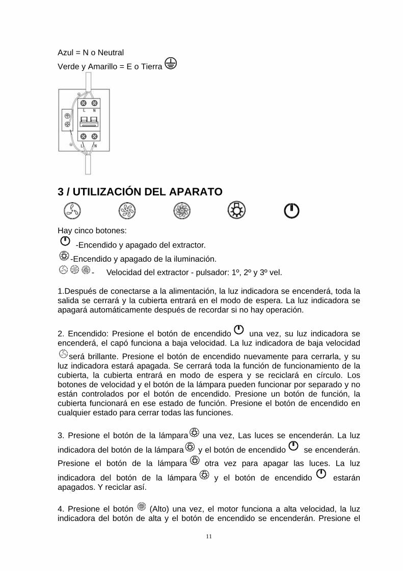
Azul = N o Neutral
Verde y Amarillo = E o Tierra
3 / UTILIZACIÓN DEL APARATO
Hay cinco botones:
-Encendido y apagado del extractor.
-Encendido y apagado de la iluminación.
- Velocidad del extractor - pulsador: 1º, 2º y 3º vel. 1.Después de conectarse a la alimentación, la luz indicadora se encenderá, toda la salida se cerrará y la cubierta entrará en el modo de espera. La luz indicadora se apagará automáticamente después de recordar si no hay operación.
2. Encendido: Presione el botón de encendido una vez, su luz indicadora se encenderá, el capó funciona a baja velocidad. La luz indicadora de baja velocidad
será brillante. Presione el botón de encendido nuevamente para cerrarla, y su luz indicadora estará apagada. Se cerrará toda la función de funcionamiento de la cubierta, la cubierta entrará en modo de espera y se reciclará en círculo. Los botones de velocidad y el botón de la lámpara pueden funcionar por separado y no están controlados por el botón de encendido. Presione un botón de función, la cubierta funcionará en ese estado de función. Presione el botón de encendido en cualquier estado para cerrar todas las funciones.
3. Presione el botón de la lámpara una vez, Las luces se encenderán. La luz
indicadora del botón de la lámpara y el botón de encendido se encenderán.
Presione el botón de la lámpara otra vez para apagar las luces. La luz
indicadora del botón de la lámpara y el botón de encendido estarán apagados. Y reciclar así.
4. Presione el botón (Alto) una vez, el motor funciona a alta velocidad, la luz indicadora del botón de alta y el botón de encendido se encenderán. Presione el
12
botón alto nuevamente y el motor se detendrá. La luz indicadora del botón alto y
el botón de encendido se apagará y se reciclará en círculo.
5. Presione el botón (Medio) una vez, el motor funciona a velocidad media, la
luz indicadora del botón medio y el botón de encendido se encenderán.
Presione nuevamente el botón central y el motor se detendrá. La luz indicadora del botón central y del botón de encendido se apagará y se reciclará en círculo.
6. Presione el botón (bajo) una vez, el motor funciona a baja velocidad, la luz
indicadora del botón bajo y el botón de encendido se encenderán. Presione
nuevamente el botón bajo y el motor se detendrá. La luz indicadora de botón
bajo y botón de encendido estará apagada y se reciclará en círculo. 7. La velocidad baja, la velocidad media y la velocidad alta no pueden funcionar al mismo tiempo. Cuando la campana está en alta velocidad, presione baja velocidad, girará a baja velocidad de una vez; cuando esté en velocidad baja, presione la velocidad media, girará a la velocidad media inmediatamente, y así sucesivamente.
4 / MANTENIMIENTO Y LIMPIEZA DEL APARATO
Atención Desconecte el aparato antes de proceder al mantenimiento y limpieza del aparato. Un mantenimiento periódico es una garantía de buen funcionamiento, buen rendimiento y duración.
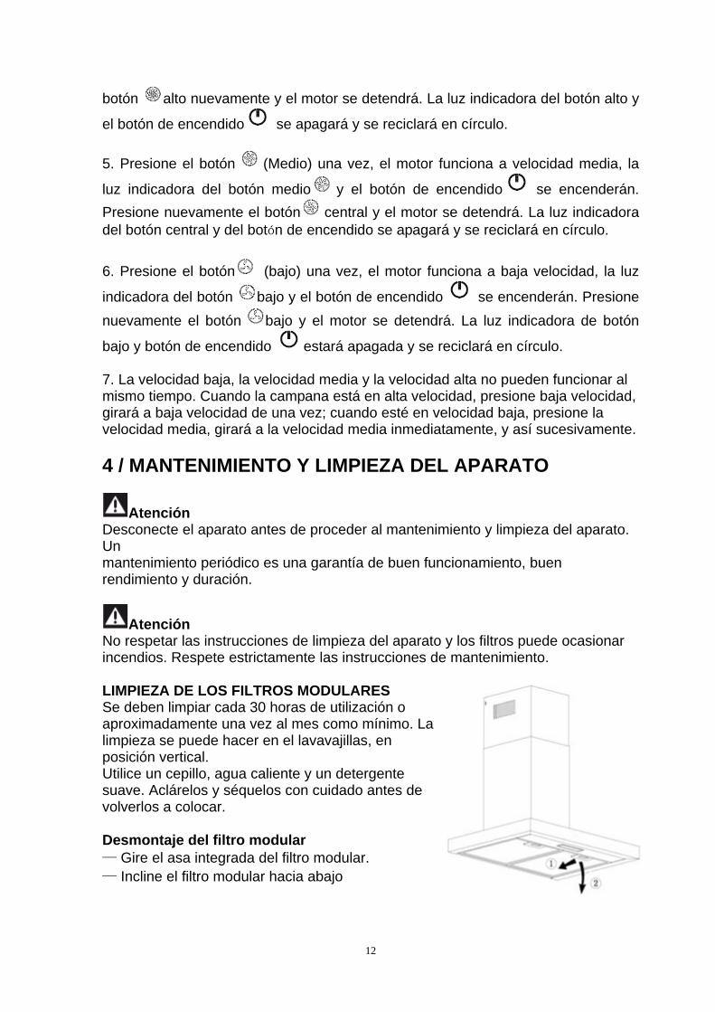
Atención No respetar las instrucciones de limpieza del aparato y los filtros puede ocasionar incendios. Respete estrictamente las instrucciones de mantenimiento. LIMPIEZA DE LOS FILTROS MODULARES Se deben limpiar cada 30 horas de utilización o aproximadamente una vez al mes como mínimo. La limpieza se puede hacer en el lavavajillas, en posición vertical. Utilice un cepillo, agua caliente y un detergente suave. Aclárelos y séquelos con cuidado antes de volverlos a colocar. Desmontaje del filtro modular — Gire el asa integrada del filtro modular. — Incline el filtro modular hacia abajo
13
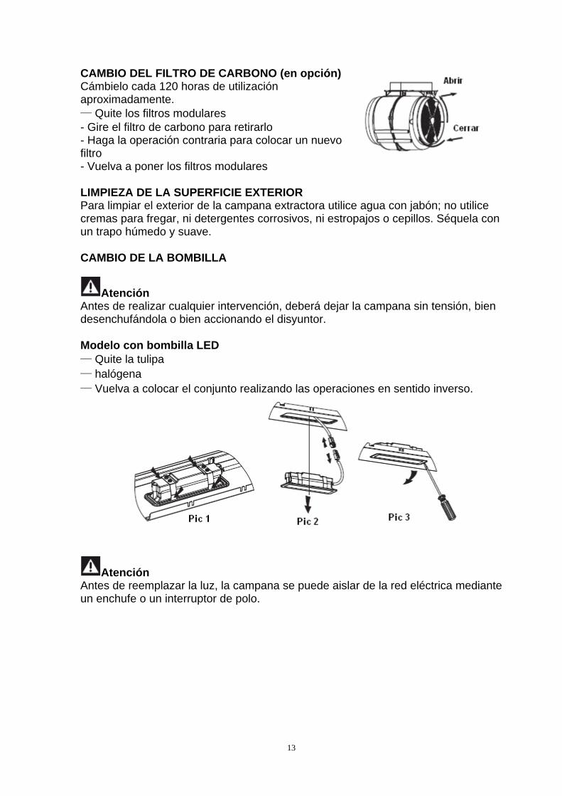
CAMBIO DEL FILTRO DE CARBONO (en opción) Cámbielo cada 120 horas de utilización aproximadamente. — Quite los filtros modulares - Gire el filtro de carbono para retirarlo - Haga la operación contraria para colocar un nuevo filtro - Vuelva a poner los filtros modulares LIMPIEZA DE LA SUPERFICIE EXTERIOR Para limpiar el exterior de la campana extractora utilice agua con jabón; no utilice cremas para fregar, ni detergentes corrosivos, ni estropajos o cepillos. Séquela con un trapo húmedo y suave. CAMBIO DE LA BOMBILLA
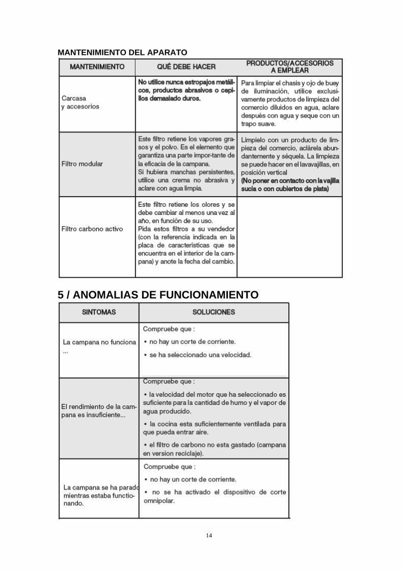
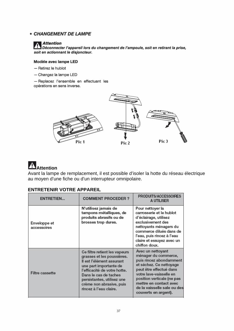
Atención Antes de realizar cualquier intervención, deberá dejar la campana sin tensión, bien desenchufándola o bien accionando el disyuntor. Modelo con bombilla LED — Quite la tulipa — halógena — Vuelva a colocar el conjunto realizando las operaciones en sentido inverso.
Atención Antes de reemplazar la luz, la campana se puede aislar de la red eléctrica mediante un enchufe o un interruptor de polo.
14
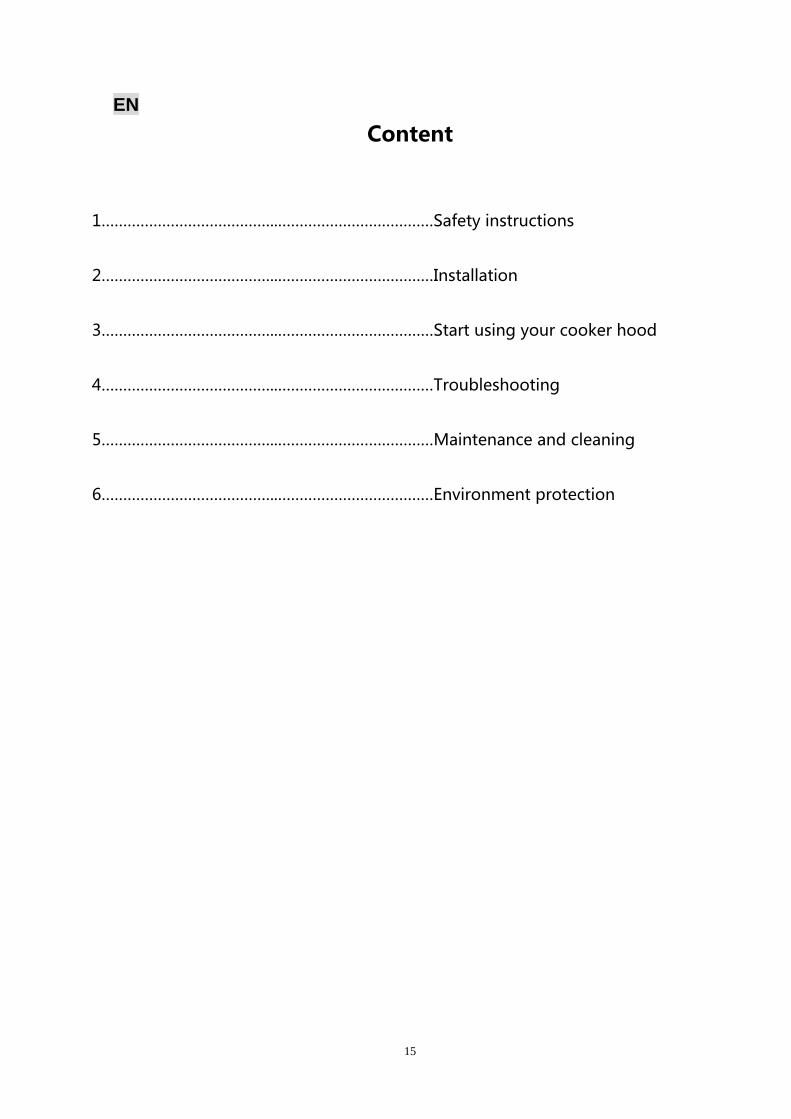
MANTENIMIENTO DEL APARATO
5 / ANOMALIAS DE FUNCIONAMIENTO
15
EN
Content
1…………………………………..………………………………Safety instructions
2…………………………………..………………………………Installation
3…………………………………..………………………………Start using your cooker hood
4…………………………………..………………………………Troubleshooting
5…………………………………..………………………………Maintenance and cleaning
SAFETY INSTRUCTIONS This manual explains the proper installation and use of your cooker hood,
please read it carefully before using even if you are familiar with the product.
The manual should be kept in a safe place for future reference.
Never to do: ● Do not try to use the cooker hood
without the grease filters or if the filters are excessively greasy!
●Do not install above a cooker with a high level grill.
●Do not leave frying pans unattended during use because overheated fats or oils might catch fire.
●Never leave naked flames under the cooker hood.
●If the cooker hood is damaged, do not
attempt to use. ●Do not flambé under the cooker hood.
●CAUTION: Accessible parts may become hot when used with cooking appliances.
●The minimum distance between the supporting surface for the cooking vessels on the hob and the lowest part of the cooker hood. (When the cooker hood is located above a gas appliance, this distance shall be at least 65 cm)
●The air must not be discharged into a flue that is used for exhausting fumes from appliances burning gas or other fuels.
Always to do: ● Important! Always switch off the
electricity supply at the mains during installation and maintenance such as light bulb replacement.
●The cooker hood must be installed in accordance with the installation instructions and all measurements followed.
●All installation work must be carried out by a competent person or qualified electrician.
●Please dispose of the packing material carefully. Children are vulnerable to it.
● Pay attention to the sharp edges inside the cooker hood especially during installation and cleaning.
●Make sure the ducting has no bends sharper than 90 degrees as this will reduce the efficiency of the cooker hood.
●Warning: Failure to install the screws or fixing device in accordance with these instructions may result in electrical hazards
●Warning: Before obtaining access to terminals, all supply circuits must be disconnected.
17
Always to do: ●Always put lids on pots and pans
when cooking on a gas cooker. ●When in extraction mode, air in the
room is being removed by the cooker hood. Please make sure that proper ventilation measures are being observed. The cooker hood removes odours from room but not steam.
●Cooker hood is for domestic use only.
●If the supply cord is damaged, it must
be replaced by the manufacturer, its service agent or similarly qualified persons in order to avoid a hazard.
●This appliance can be used by children aged from 8 years and above and persons with reduced physical, sensory or mental capabilities or lack of experience and knowledge if they have been given supervision or instruction concerning use of the appliance in a safe way and understand the hazards involved. Children shall not play with the appliance. Cleaning and user maintenance shall not be made by children without supervision.
●Warning: Before obtaining access to
terminals, all supply circuits must be disconnected.
Always to do: ● Caution: The appliance and its
accessible parts can become hot during operation. Be careful to avoid touching the heating elements. Children younger than 8 years old should stay away unless they are under permanent supervision.
● There shall be adequate ventilation of the room when the cooker hood is used at the same time as appliances burning gas or other fuels.
●There is a fire risk if cleaning is not carried out in accordance with the instructions
●Regulations concerning the discharge of air have to be fulfilled.
●Clean your appliance periodically by following the method given in the chapter MAINTENANCE.
●For safety reason, please use only the same size of fixing or mounting screw which are recommended in this instruction manual.
●Regarding the details about the method and frequency of cleaning, please refer to maintenance and cleaning section in the instruction manual.
●Cleaning and user maintenance shall not be made by children without supervision.
●When the cooker hood and appliances supplied with energy other than electricity are simultaneously in operation, the negative pressure in the room must not exceed 4 Pa (4 x 10⁻⁵ bar).
●WARNING: Danger of fire: do not store items on the cooking surfaces.
●A steam cleaner is not to be used.
●NEVER try to extinguish a fire with water, but switch off the appliance and then cover flame e.g. with a lid or a fire blanket.
18
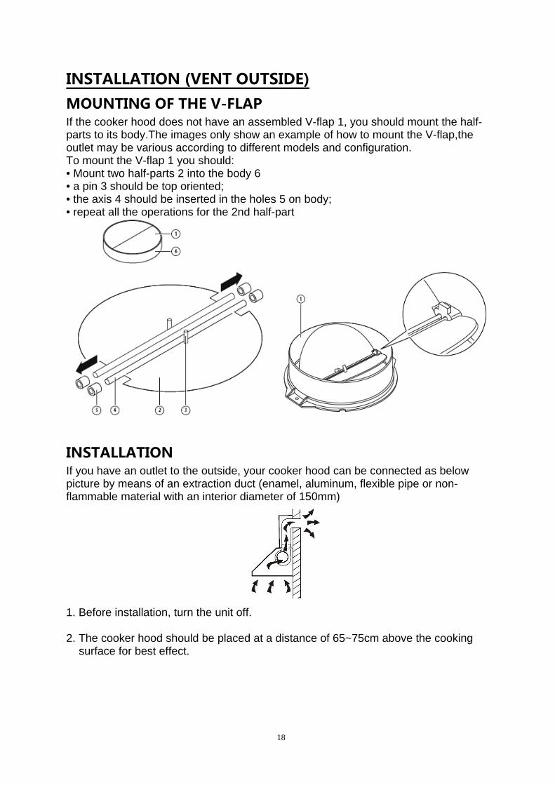
INSTALLATION (VENT OUTSIDE) MOUNTING OF THE V-FLAP If the cooker hood does not have an assembled V-flap 1, you should mount the half-parts to its body.The images only show an example of how to mount the V-flap,the outlet may be various according to different models and configuration. To mount the V-flap 1 you should: • Mount two half-parts 2 into the body 6 • a pin 3 should be top oriented; • the axis 4 should be inserted in the holes 5 on body; • repeat all the operations for the 2nd half-part
INSTALLATION If you have an outlet to the outside, your cooker hood can be connected as below picture by means of an extraction duct (enamel, aluminum, flexible pipe or non-flammable material with an interior diameter of 150mm)
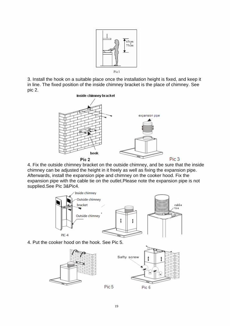
1. Before installation, turn the unit off. 2. The cooker hood should be placed at a distance of 65~75cm above the cooking
surface for best effect.
19
3. Install the hook on a suitable place once the installation height is fixed, and keep it in line. The fixed position of the inside chimney bracket is the place of chimney. See pic 2.
4. Fix the outside chimney bracket on the outside chimney, and be sure that the inside chimney can be adjusted the height in it freely as well as fixing the expansion pipe. Afterwards, install the expansion pipe and chimney on the cooker hood. Fix the expansion pipe with the cable tie on the outlet.Please note the expansion pipe is not supplied.See Pic 3&Pic4.
4. Put the cooker hood on the hook. See Pic 5.
20
5. Adjust the height of the inside chimney to the position of the inside chimney bracket and fix on it by screw, after adjusting the position, fix the body with safety screw. Note:The two safety vents are positioned on the back housing, with diameter of 6mm. See Pic 6.
Electrical Installation All installation must be carried out by a competent person or qualified electrician.
Before connecting the mains supply ensure that the mains voltage corresponds to the
voltage on the rating plate.
Direct Connection
The appliance must be connected directly to the mains using an omnipolar circuit
breaker with a
minimum opening of 3mm between the contacts.
The installer must ensure that the correct electrical connection has been made and
that it complies with the wiring diagram.
The cable must not be bent or compressed.
Regularly check the power plug and power cord for damage. If the supply cord is
damaged, it must be replaced by a special cord or assembly available from the
manufacturer or its service agent.
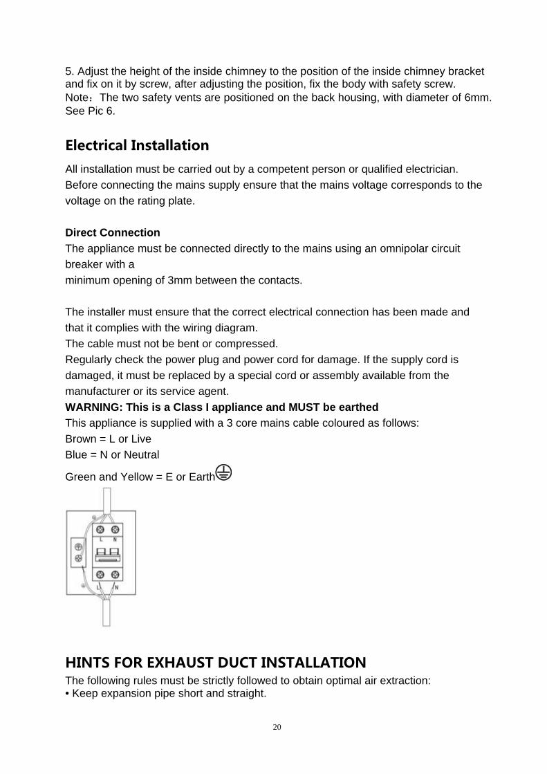
WARNING: This is a Class I appliance and MUST be earthed
This appliance is supplied with a 3 core mains cable coloured as follows:
Brown = L or Live
Blue = N or Neutral
Green and Yellow = E or Earth
HINTS FOR EXHAUST DUCT INSTALLATION The following rules must be strictly followed to obtain optimal air extraction: • Keep expansion pipe short and straight.
21
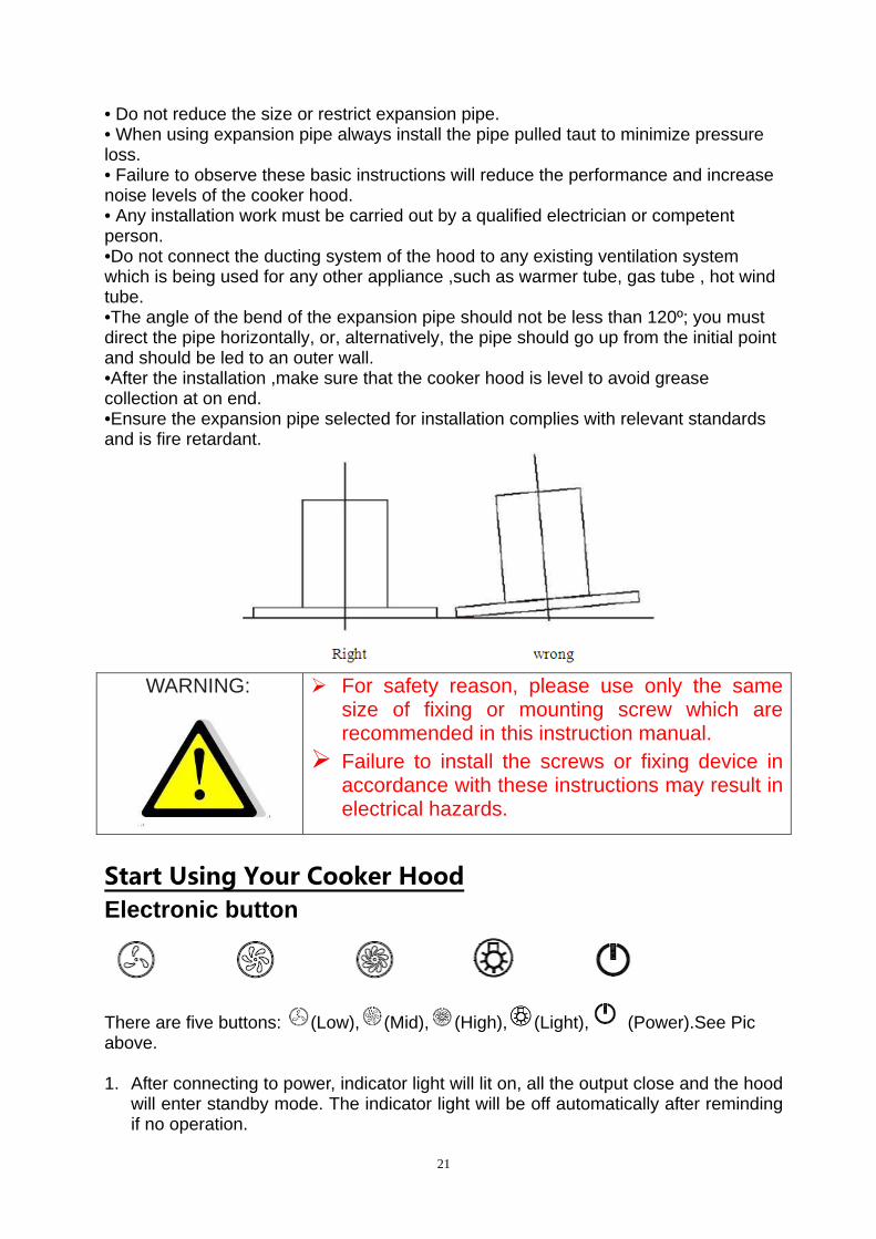
• Do not reduce the size or restrict expansion pipe. • When using expansion pipe always install the pipe pulled taut to minimize pressure loss. • Failure to observe these basic instructions will reduce the performance and increase noise levels of the cooker hood. • Any installation work must be carried out by a qualified electrician or competent person. •Do not connect the ducting system of the hood to any existing ventilation system which is being used for any other appliance ,such as warmer tube, gas tube , hot wind tube. •The angle of the bend of the expansion pipe should not be less than 120º; you must direct the pipe horizontally, or, alternatively, the pipe should go up from the initial point and should be led to an outer wall. •After the installation ,make sure that the cooker hood is level to avoid grease collection at on end. •Ensure the expansion pipe selected for installation complies with relevant standards and is fire retardant.
WARNING:
For safety reason, please use only the same size of fixing or mounting screw which are recommended in this instruction manual.
Failure to install the screws or fixing device in accordance with these instructions may result in electrical hazards.
Start Using Your Cooker Hood
Electronic button
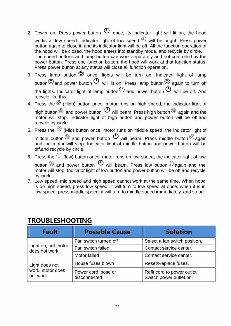
There are five buttons: (Low), (Mid), (High), (Light), (Power).See Pic above. 1. After connecting to power, indicator light will lit on, all the output close and the hood
will enter standby mode. The indicator light will be off automatically after reminding if no operation.
22
2. Power on: Press power button once, its indicator light will lit on, the hood
works at low speed. Indicator light of low speed will be bright. Press power button again to close it, and its indicator light will be off. All the function operation of the hood will be closed, the hood enters into standby mode, and recycle by circle. The speed buttons and lamp button can work separately and not controlled by the power button. Press one function button, the hood will work at that function status. Press power button at any status will close all function operation.
3. Press lamp button once; lights will be turn on. Indicator light of lamp
button and power button will lit on. Press lamp button again to turn off
the lights. Indicator light of lamp button and power button will be off. And recycle like this.
4. Press the (High) button once, motor runs on high speed, the indicator light of
high button and power button will beam. Press high button again and the motor will stop. Indicator light of high button and power button will be off,and recycle by circle.
5. Press the (Mid) button once, motor runs on middle speed, the indicator light of
middle button and power button will beam. Press middle button again and the motor will stop. Indicator light of middle button and power button will be off,and recycle by circle.
6. Press the (low) button once, motor runs on low speed, the indicator light of low
button and power button will beam. Press low button again and the motor will stop. Indicator light of low button and power button will be off,and recycle by circle.
7. Low speed, mid speed and high speed cannot work at the same time. When hood is on high speed, press low speed, it will turn to low speed at once; when it is in low speed, press middle speed, it will turn to middle speed immediately, and so on.
TROUBLESHOOTING
Fault Possible Cause Solution
Light on, but motor does not work
Fan switch turned off Select a fan switch position.
Fan switch failed Contact service center.
Motor failed Contact service center.
Light does not work, motor does not work
House fuses blown Reset/Replace fuses.
Power cord loose or disconnected
Refit cord to power outlet. Switch power outlet on.
23
Oil leakage
One way valve and the outlet are not tightly sealed
Take down the one way valve and seal with sealant.
Leakage from the connection of chimney and cover
Take chimney down and seal.
Lights not working Broken/Faulty globes Replace globes as per this instruction.
Insufficient suction The distance between the cooker hood and the gas top is too far
Refit the cooker hood to the correct distance.
The Cooker hood inclines
The fixing screw not tight enough
Tighten the hanging screw and make it horizontal.
NOTE: Any electrical repairs to this appliance must conform to your local, state and federal laws.Please contact the service centre if in any doubt before
undertaking any of the above.Always disconnect the unit from the power source when opening the unit.
MAINTENANCE AND CLEANING Caution: • Before maintenance or cleaning is carried out, the cooker hood should be
disconnected from the main power supply. Ensure that the cooker hood is switched off at the wall socket.
• External surfaces are susceptible to scratches and abrasions, so please follow the
cleaning instructions to ensure the best possible result is achieved without damage. GENERAL Cleaning and maintenance should be carried out with the appliance cold especially when cleaning.Avoid leaving alkaline or acid substances (lemon juice, vinegar etc.) on the surfaces. STAINLESS STEEL The stainless steel must be cleaned regularly (e.g.weekly) to ensure long life expectancy.Dry with a clean soft cloth. A specialized stainless steel cleaning fluid may be used. NOTE: Ensure that wiping is done along with the grain of the stainless steel to prevent any unsightly crisscross scratching patterns from appearing. CONTROL PANEL SURFACE The inlay control panel can be cleaned using warm soapy water. Ensure the cloth is clean and well wrung before cleaning. Use a dry soft cloth to remove any excess moisture left after cleaning.
24
Important Using neutral detergents and avoid using harsh cleaning chemicals, strong household detergents or products containing abrasives,as this will affect the appliance appearance and potentially remove any printing of artwork on the control panel and will void manufactures warrantee.
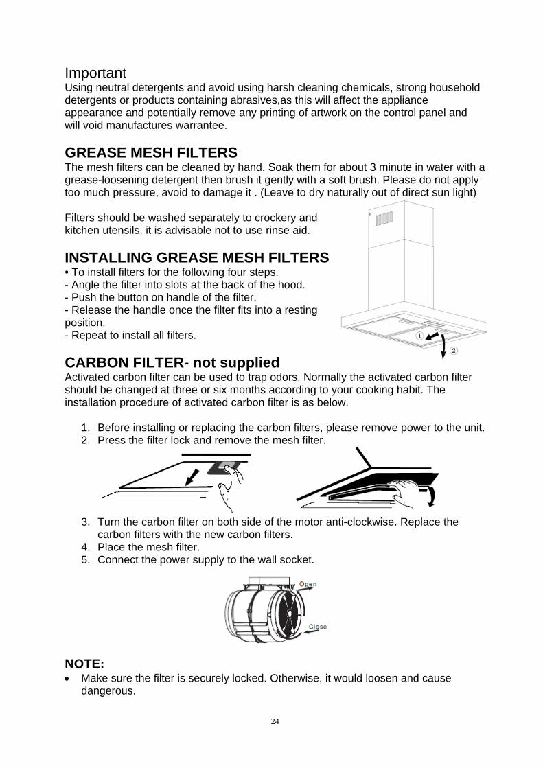
GREASE MESH FILTERS The mesh filters can be cleaned by hand. Soak them for about 3 minute in water with a grease-loosening detergent then brush it gently with a soft brush. Please do not apply too much pressure, avoid to damage it . (Leave to dry naturally out of direct sun light)
Filters should be washed separately to crockery and kitchen utensils. it is advisable not to use rinse aid.
INSTALLING GREASE MESH FILTERS • To install filters for the following four steps. - Angle the filter into slots at the back of the hood. - Push the button on handle of the filter. - Release the handle once the filter fits into a resting position. - Repeat to install all filters.
CARBON FILTER- not supplied Activated carbon filter can be used to trap odors. Normally the activated carbon filter should be changed at three or six months according to your cooking habit. The installation procedure of activated carbon filter is as below.
1. Before installing or replacing the carbon filters, please remove power to the unit. 2. Press the filter lock and remove the mesh filter.
3. Turn the carbon filter on both side of the motor anti-clockwise. Replace the
carbon filters with the new carbon filters. 4. Place the mesh filter. 5. Connect the power supply to the wall socket.
NOTE: Make sure the filter is securely locked. Otherwise, it would loosen and cause
dangerous.
25
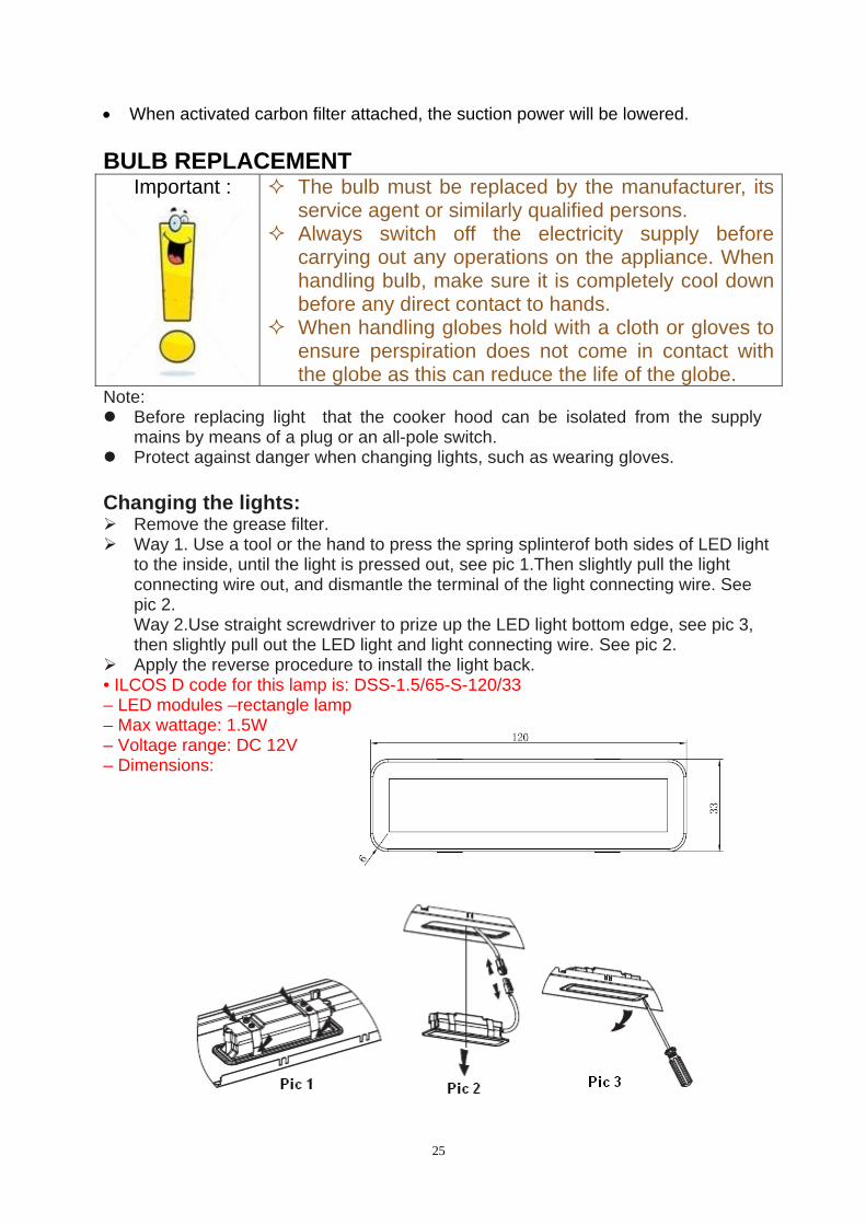
When activated carbon filter attached, the suction power will be lowered. BULB REPLACEMENT
Important :
The bulb must be replaced by the manufacturer, its service agent or similarly qualified persons.
Always switch off the electricity supply before carrying out any operations on the appliance. When handling bulb, make sure it is completely cool down before any direct contact to hands.
When handling globes hold with a cloth or gloves to ensure perspiration does not come in contact with the globe as this can reduce the life of the globe.
Note: Before replacing light that the cooker hood can be isolated from the supply
mains by means of a plug or an all-pole switch. Protect against danger when changing lights, such as wearing gloves. Changing the lights: Remove the grease filter. Way 1. Use a tool or the hand to press the spring splinterof both sides of LED light
to the inside, until the light is pressed out, see pic 1.Then slightly pull the light connecting wire out, and dismantle the terminal of the light connecting wire. See pic 2. Way 2.Use straight screwdriver to prize up the LED light bottom edge, see pic 3, then slightly pull out the LED light and light connecting wire. See pic 2.
Apply the reverse procedure to install the light back. • ILCOS D code for this lamp is: DSS-1.5/65-S-120/33 – LED modules –rectangle lamp – Max wattage: 1.5W – Voltage range: DC 12V – Dimensions:
26
ENVIRONMENTAL PROTECTION: This product is marked with the symbol on the selective sorting of
waste electronic equipment. This means that this product must not be disposed of with household waste but must be supported by a system of selective collection in accordance with Directive 2012/19/EU. It will then be recycled or dismantled to minimize impacts on the environment, electrical and electronic products are potentially dangerous for the environment and human health due to the presence of hazardous substances.For more information, please contact your local or regional authorities.
NOTE: The following shows how to reduce total environmental impact (e.g. energy use) of the cooking process).
(1) Install the cooker hood in a proper place where there is efficient ventilation. (2) Clean the cooker hood regularly so as not to block the airway. (3) Remember to switch off the cooker hood light after cooking. (4) Remember to switch off the cooker hood after cooking.
INFORMATION FOR DISMANTLING Do not dismantle the appliance in a way which is not shown in the user manual. The appliance could not be dismantled by user. At the end of life, the appliance should not be disposed of with household waste. Check with you Local Authority or retainer for recycling advice.
27
FR
SOMMAIRE
1 / A L’ATTENTION DE L’UTILISATEUR
2 / INSTALLATION DE VOTRE APPAREIL
3 / UTILISATION DE VOTRE APPAREIL
4 / ENTRETIEN ET NETTOYAGE DE VOTRE APPAREIL
5 / ANOMALIES DE FONCTIONNEMENT
28
29
30
31
1/A L’ATTENTION DE L’UTILISATEUR RESPECT DE L’ENVIRONNEMENT — Les matériaux d’emballage de cet appareil sont recyclables. Participez à leur recyclage et contribuez ainsi à la protection de l’environnement en les déposant dans les conteneurs municipaux prévus à cet effet. — Votre appareil contient également de nombreux matériaux recyclables. Il est donc marquee de ce logo afi n de vous indiquer que les appareils usagés ne doivent pas être mélangés avec d’autres déchets. Le recyclage des appareils qu’organise votre fabricant sera ainsi réalisé dans les meilleures conditions, conformément à la directive
européenne 2002/96/CE sur les déchets d’équipements électriques et électroniques. Adressez vous à votre mairie ou à votre revendeur pour connaître les points de collecte des appareils usagés les plus proches de votre domicile. — Nous vous remercions pour votre collaboration à la protection de l’environnement.
Attention L’installation est réservée aux installateurs et techniciens qualifi és. Avant la première utilisation du fi ltre cassette, retirez le fi lm de protection.
32
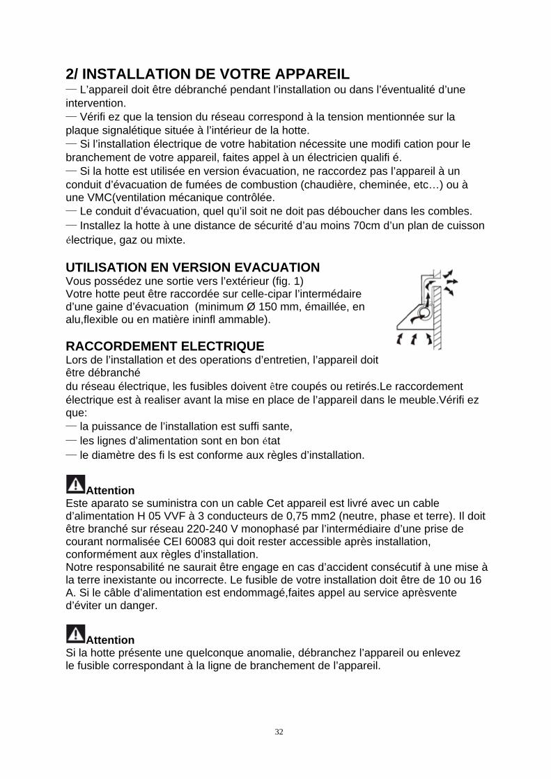
2/ INSTALLATION DE VOTRE APPAREIL — L’appareil doit être débranché pendant l’installation ou dans l’éventualité d’une intervention. — Vérifi ez que la tension du réseau correspond à la tension mentionnée sur la plaque signalétique située à l’intérieur de la hotte. — Si l’installation électrique de votre habitation nécessite une modifi cation pour le branchement de votre appareil, faites appel à un électricien qualifi é. — Si la hotte est utilisée en version évacuation, ne raccordez pas l’appareil à un conduit d’évacuation de fumées de combustion (chaudière, cheminée, etc…) ou à une VMC(ventilation mécanique contrôlée. — Le conduit d’évacuation, quel qu’il soit ne doit pas déboucher dans les combles. — Installez la hotte à une distance de sécurité d’au moins 70cm d’un plan de cuisson électrique, gaz ou mixte. UTILISATION EN VERSION EVACUATION Vous possédez une sortie vers l’extérieur (fig. 1) Votre hotte peut être raccordée sur celle-cipar l’intermédaire d’une gaine d’évacuation (minimum Ø 150 mm, émaillée, en alu,flexible ou en matière ininfl ammable). RACCORDEMENT ELECTRIQUE Lors de l’installation et des operations d’entretien, l’appareil doit être débranché du réseau électrique, les fusibles doivent être coupés ou retirés.Le raccordement électrique est à realiser avant la mise en place de l’appareil dans le meuble.Vérifi ez que: — la puissance de l’installation est suffi sante, — les lignes d’alimentation sont en bon état — le diamètre des fi ls est conforme aux règles d’installation.
Attention Este aparato se suministra con un cable Cet appareil est livré avec un cable d’alimentation H 05 VVF à 3 conducteurs de 0,75 mm2 (neutre, phase et terre). Il doit être branché sur réseau 220-240 V monophasé par l’intermédiaire d’une prise de courant normalisée CEI 60083 qui doit rester accessible après installation, conformément aux règles d’installation. Notre responsabilité ne saurait être engage en cas d’accident consécutif à une mise à la terre inexistante ou incorrecte. Le fusible de votre installation doit être de 10 ou 16 A. Si le câble d’alimentation est endommagé,faites appel au service aprèsvente d’éviter un danger.
Attention Si la hotte présente une quelconque anomalie, débranchez l’appareil ou enlevez le fusible correspondant à la ligne de branchement de l’appareil.
33
MONTAGE DE LA HOTTE
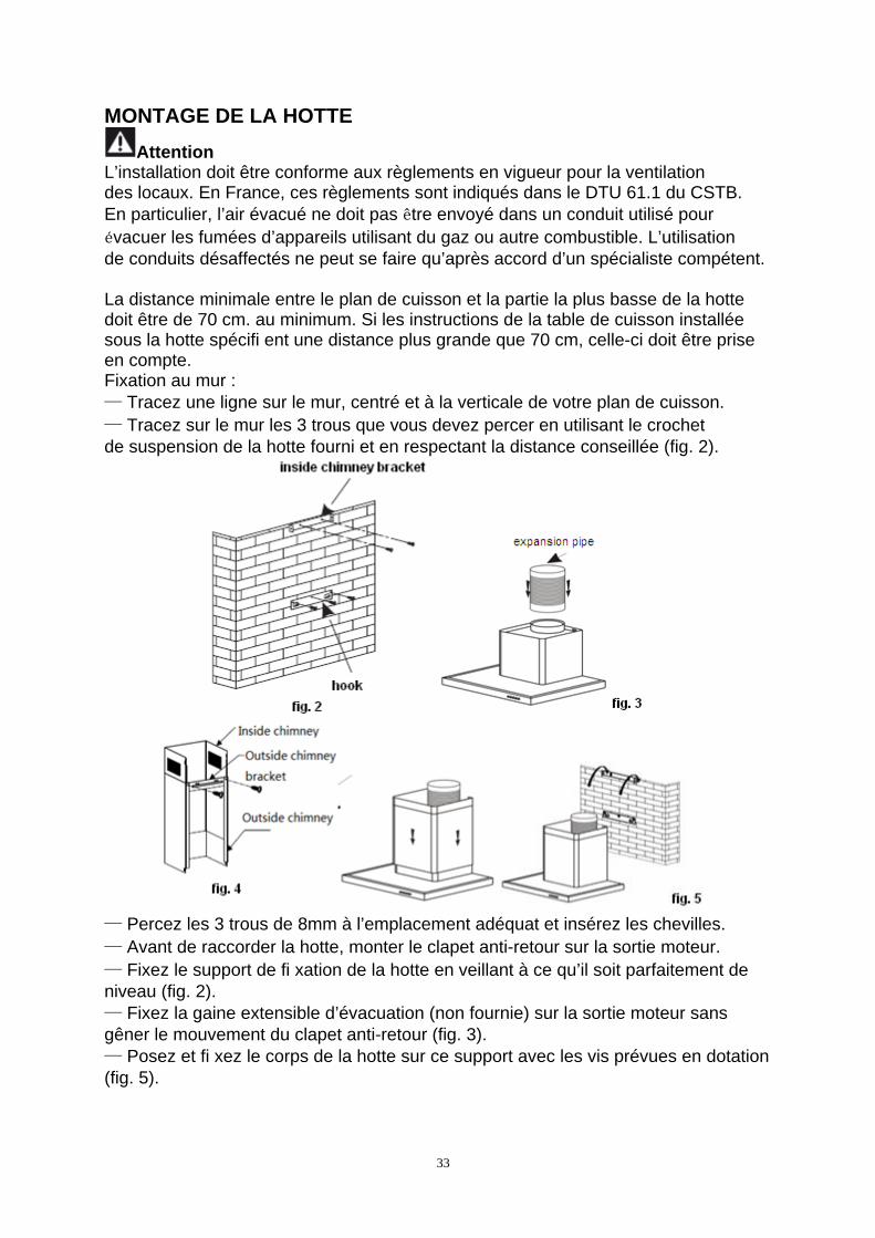
Attention L’installation doit être conforme aux règlements en vigueur pour la ventilation des locaux. En France, ces règlements sont indiqués dans le DTU 61.1 du CSTB. En particulier, l’air évacué ne doit pas être envoyé dans un conduit utilisé pour évacuer les fumées d’appareils utilisant du gaz ou autre combustible. L’utilisation de conduits désaffectés ne peut se faire qu’après accord d’un spécialiste compétent. La distance minimale entre le plan de cuisson et la partie la plus basse de la hotte doit être de 70 cm. au minimum. Si les instructions de la table de cuisson installée sous la hotte spécifi ent une distance plus grande que 70 cm, celle-ci doit être prise en compte. Fixation au mur : — Tracez une ligne sur le mur, centré et à la verticale de votre plan de cuisson. — Tracez sur le mur les 3 trous que vous devez percer en utilisant le crochet de suspension de la hotte fourni et en respectant la distance conseillée (fig. 2).
— Percez les 3 trous de 8mm à l’emplacement adéquat et insérez les chevilles. — Avant de raccorder la hotte, monter le clapet anti-retour sur la sortie moteur. — Fixez le support de fi xation de la hotte en veillant à ce qu’il soit parfaitement de niveau (fig. 2). — Fixez la gaine extensible d’évacuation (non fournie) sur la sortie moteur sans gêner le mouvement du clapet anti-retour (fig. 3). — Posez et fi xez le corps de la hotte sur ce support avec les vis prévues en dotation (fig. 5).
34
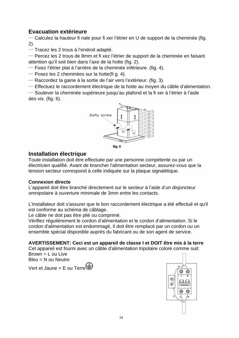
Evacuation extérieure — Calculez la hauteur fi nale pour fi xer l’étrier en U de support de la cheminée (fig. 2). — Tracez les 2 trous à l’endroit adapté. — Percez les 2 trous de 8mm et fi xez l’étrier de support de la cheminée en faisant attention qu’il soit bien dans l’axe de la hotte (fig. 2). — Fixez l’étrier plat à l’arrière de la cheminée inférieure. (fig. 4). — Posez les 2 cheminées sur la hotte(fi g. 4). — Raccordez la gaine à la sortie de l’air vers l’extérieur. (fig. 3). — Effectuez le raccordement électrique de la hotte au moyen du câble d’alimentation. — Soulever la cheminée supérieure jusqu’au plafond et la fi xer à l’étrier à l’aide des vis. (fig. 6).
Installation électrique Toute installation doit être effectuée par une personne compétente ou par un électricien qualifié. Avant de brancher l'alimentation secteur, assurez-vous que la tension secteur correspond à celle indiquée sur la plaque signalétique. Connexion directe L’appareil doit être branché directement sur le secteur à l’aide d’un disjoncteur omnipolaire à ouverture minimale de 3mm entre les contacts. L'installateur doit s'assurer que le bon raccordement électrique a été effectué et qu'il est conforme au schéma de câblage. Le câble ne doit pas être plié ou comprimé. Vérifiez régulièrement le cordon d’alimentation et le cordon d’alimentation. Si le cordon d'alimentation est endommagé, il doit être remplacé par un cordon ou un ensemble spécial disponible auprès du fabricant ou de son agent de service. AVERTISSEMENT: Ceci est un appareil de classe I et DOIT être mis à la terre Cet appareil est fourni avec un câble d'alimentation tripolaire coloré comme suit: Brown = L ou Live Bleu = N ou Neutre
Vert et Jaune = E ou Terre
35
3 / UTILISATION DE VOTRE APPAREIL DESCRIPTION DES COMMANDES
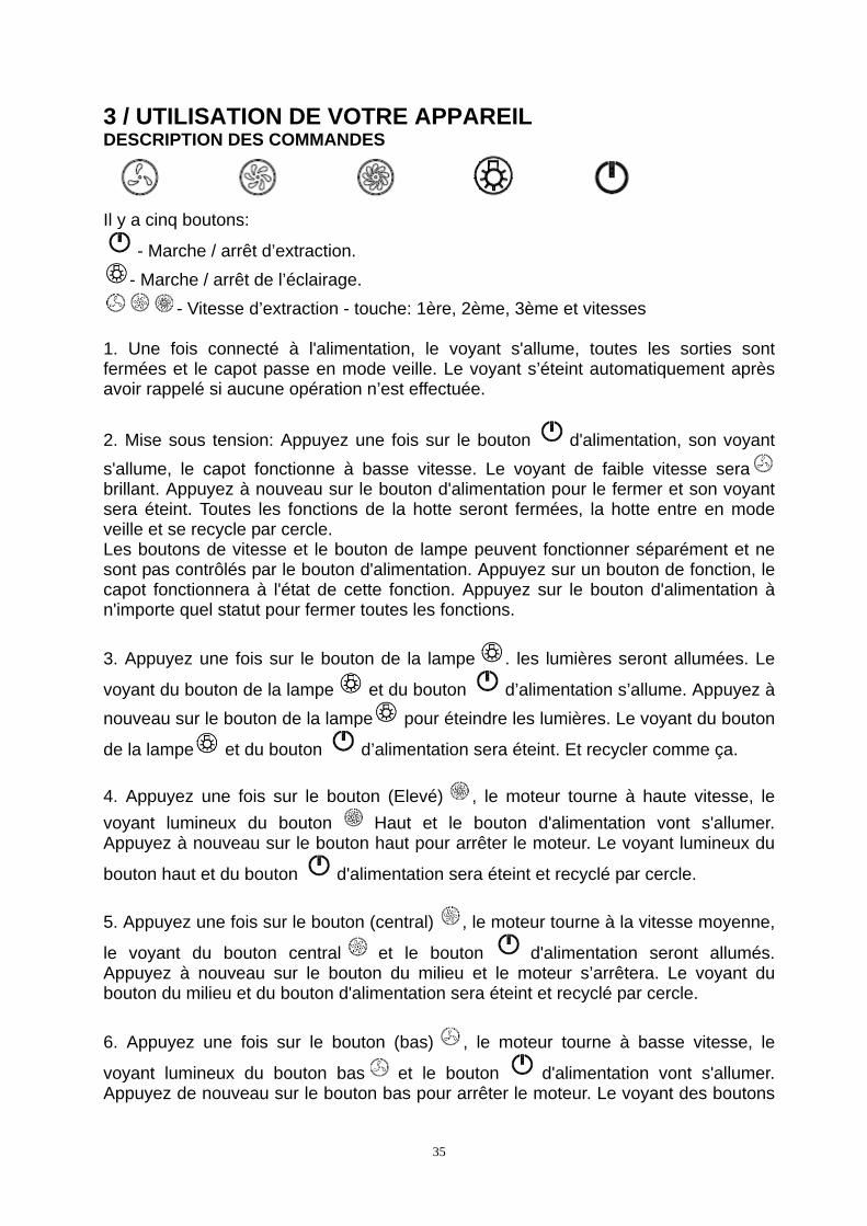
Il y a cinq boutons:
- Marche / arrêt d’extraction.
- Marche / arrêt de l’éclairage.
- Vitesse d’extraction - touche: 1ère, 2ème, 3ème et vitesses 1. Une fois connecté à l'alimentation, le voyant s'allume, toutes les sorties sont fermées et le capot passe en mode veille. Le voyant s’éteint automatiquement après avoir rappelé si aucune opération n’est effectuée.
2. Mise sous tension: Appuyez une fois sur le bouton d'alimentation, son voyant
s'allume, le capot fonctionne à basse vitesse. Le voyant de faible vitesse sera brillant. Appuyez à nouveau sur le bouton d'alimentation pour le fermer et son voyant sera éteint. Toutes les fonctions de la hotte seront fermées, la hotte entre en mode veille et se recycle par cercle. Les boutons de vitesse et le bouton de lampe peuvent fonctionner séparément et ne sont pas contrôlés par le bouton d'alimentation. Appuyez sur un bouton de fonction, le capot fonctionnera à l'état de cette fonction. Appuyez sur le bouton d'alimentation à n'importe quel statut pour fermer toutes les fonctions.
3. Appuyez une fois sur le bouton de la lampe . les lumières seront allumées. Le
voyant du bouton de la lampe et du bouton d’alimentation s’allume. Appuyez à
nouveau sur le bouton de la lampe pour éteindre les lumières. Le voyant du bouton
de la lampe et du bouton d’alimentation sera éteint. Et recycler comme ça.
4. Appuyez une fois sur le bouton (Elevé) , le moteur tourne à haute vitesse, le
voyant lumineux du bouton Haut et le bouton d'alimentation vont s'allumer. Appuyez à nouveau sur le bouton haut pour arrêter le moteur. Le voyant lumineux du
bouton haut et du bouton d'alimentation sera éteint et recyclé par cercle.
5. Appuyez une fois sur le bouton (central) , le moteur tourne à la vitesse moyenne,
le voyant du bouton central et le bouton d'alimentation seront allumés. Appuyez à nouveau sur le bouton du milieu et le moteur s’arrêtera. Le voyant du bouton du milieu et du bouton d'alimentation sera éteint et recyclé par cercle.
6. Appuyez une fois sur le bouton (bas) , le moteur tourne à basse vitesse, le
voyant lumineux du bouton bas et le bouton d'alimentation vont s'allumer. Appuyez de nouveau sur le bouton bas pour arrêter le moteur. Le voyant des boutons
36
bas et bouton d’alimentation sera éteint et sera recyclé par cercle. 7. Les vitesses basse, moyenne et haute ne peuvent pas fonctionner en même temps. Lorsque la hotte est à haute vitesse, appuyez sur basse vitesse, elle passera immédiatement à basse vitesse; quand il est à basse vitesse, appuyez sur la vitesse moyenne, il passera immédiatement à la vitesse moyenne, et ainsi de suite.
4/ENTRETIEN ET NETTOYAGE DE VOTRE APPAREIL
Attention Débranchez l’appareil avant de procéder à l’entretien et au nettoyage de l’appareil. Un entretien régulier de votre appareil est une garantie de bon fonctionnement, de bon rendement et de durabilité.
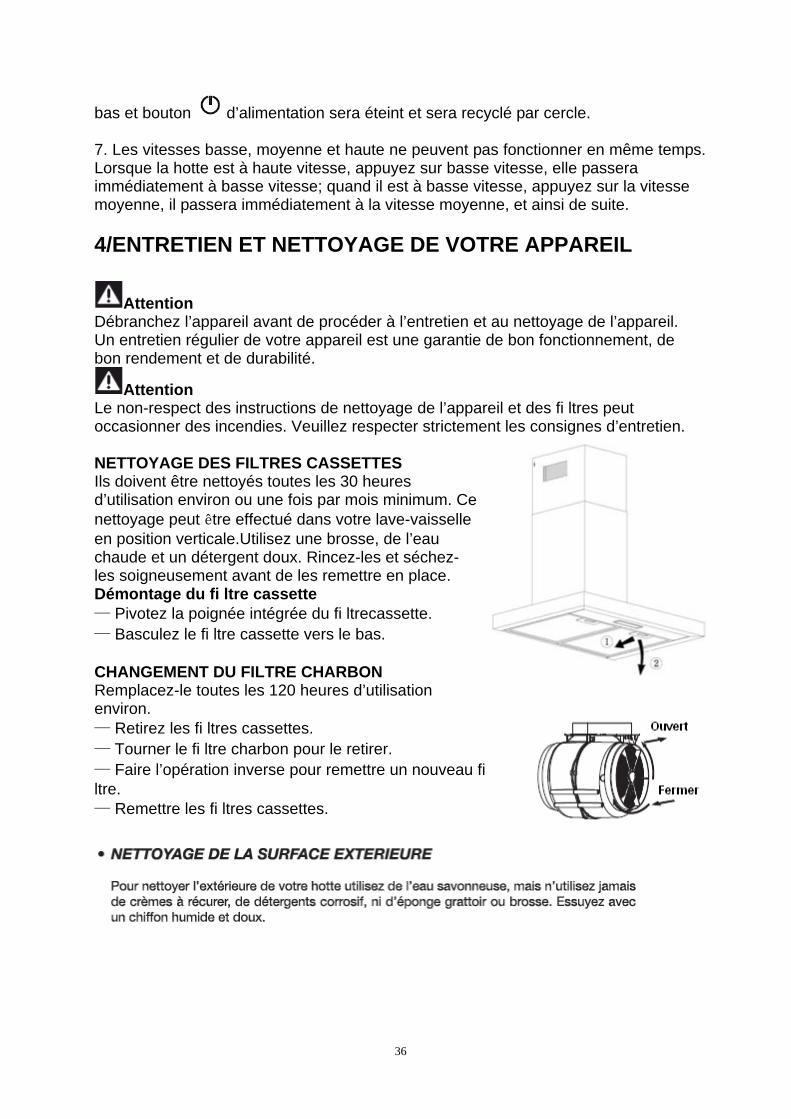
Attention Le non-respect des instructions de nettoyage de l’appareil et des fi ltres peut occasionner des incendies. Veuillez respecter strictement les consignes d’entretien. NETTOYAGE DES FILTRES CASSETTES Ils doivent être nettoyés toutes les 30 heures d’utilisation environ ou une fois par mois minimum. Ce nettoyage peut être effectué dans votre lave-vaisselle en position verticale.Utilisez une brosse, de l’eau chaude et un détergent doux. Rincez-les et séchez-les soigneusement avant de les remettre en place. Démontage du fi ltre cassette — Pivotez la poignée intégrée du fi ltrecassette. — Basculez le fi ltre cassette vers le bas. CHANGEMENT DU FILTRE CHARBON Remplacez-le toutes les 120 heures d’utilisation environ. — Retirez les fi ltres cassettes. — Tourner le fi ltre charbon pour le retirer. — Faire l’opération inverse pour remettre un nouveau fi ltre. — Remettre les fi ltres cassettes.
37
Attention Avant la lampe de remplacement, il est possible d’isoler la hotte du réseau électrique au moyen d’une fiche ou d’un interrupteur omnipolaire. ENTRETENIR VOTRE APPAREIL
38
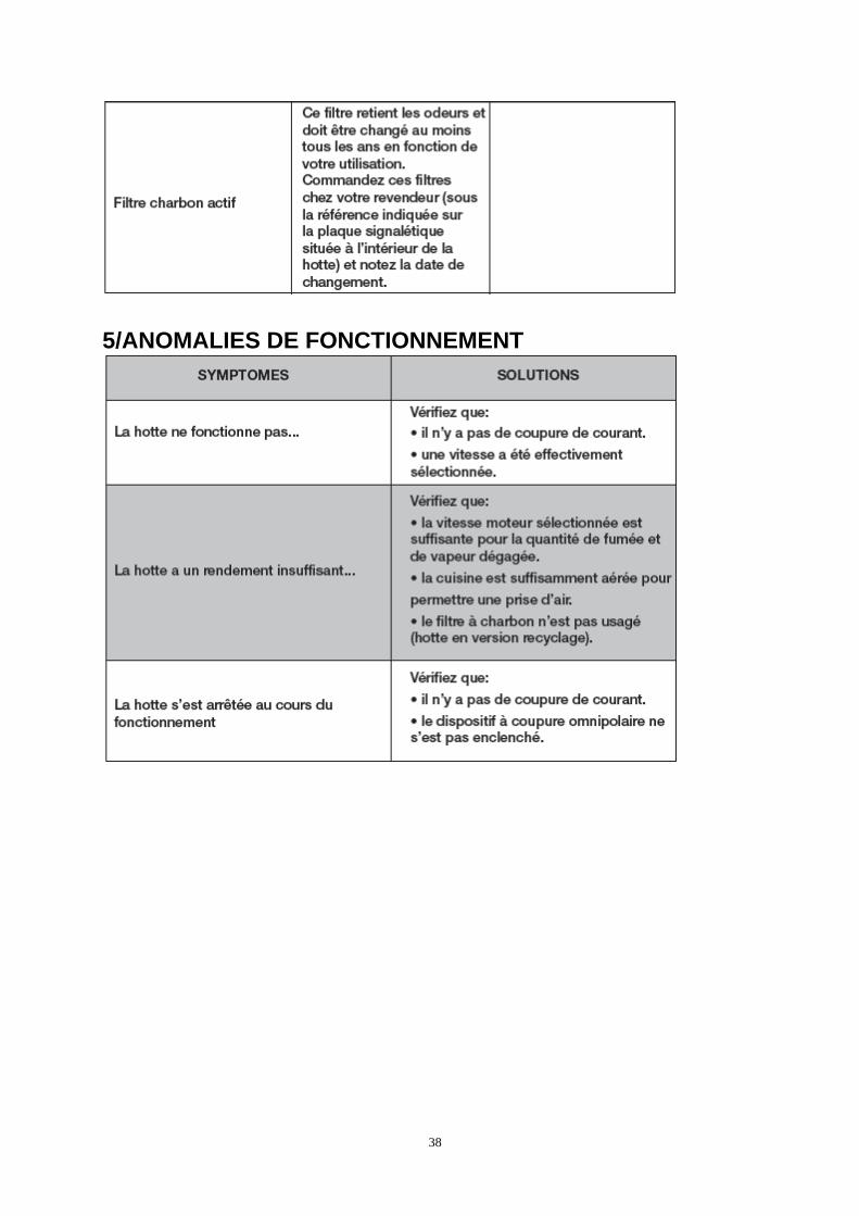
5/ANOMALIES DE FONCTIONNEMENT
39
PT
ÍNDICE
1 / INFORMAÇÕES DESTINADAS AO UTILIZADOR
2 / INSTALAÇÃO DO APARELHO
3 / UTILIZAÇÃO DO APARELHO
4 / MANUTENÇÃO E LIMPEZA DO APARELHO
5 / ANOMALIAS DE FUNCIONAMENTO
40
41
42
43
44
1 / INFORMAÇÕES DESTINADAS AO UTILIZADOR PROTECÇÃO DO AMBIENTE — Os materiais e embalagem deste aparelho são recicláveis. Por isso, participe na reciclagem dos mesmos e contribua, assim, para a protecção do ambiente, depositando-os nos contentores municipais previstos para este efeito. — Este aparelho também contém muitos materiais recicláveis. Por esta razão, está marcado com este símbolo a fi m de lhe indicar que os aparelhos usados não devem ser misturados com os restantes resíduos. A reciclagem dos aparelhos organizada pelo fabricante será, pois, efectuada nas melhores condições possíveis, de acordo com a directiva europeia 2002/96/CE sobre os resíduos
de equipamentos eléctricos e electrónicos. Consulte a sua câmara municipal ou o revendedor de forma a encontrar os pontos de recolha para aparelhos utilizados mais próximos de sua casa. — Agradecemos, desde já, a sua colaboração na protecção do ambiente.
Atenção A instalação do exaustor é reservada aos instaladores e técnicos qualifi cados.
Atenção Antes da primeira utilização do fi ltro cassete, retire a película de protecção.
45
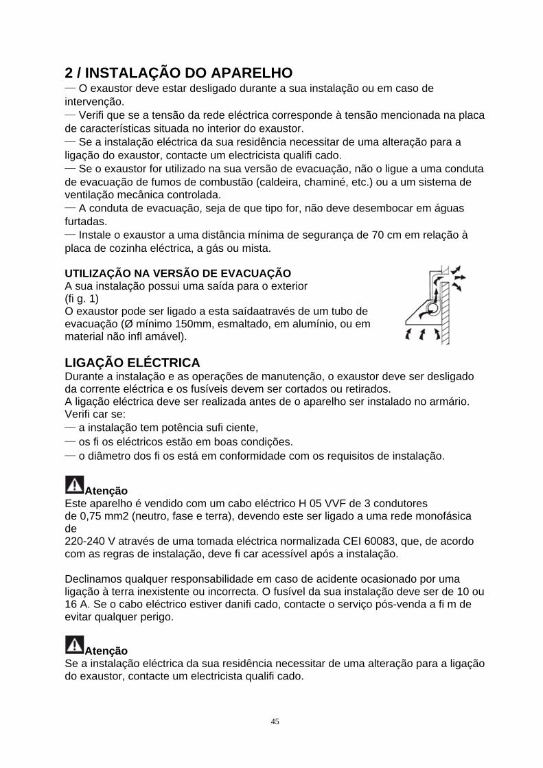
2 / INSTALAÇÃO DO APARELHO — O exaustor deve estar desligado durante a sua instalação ou em caso de intervenção. — Verifi que se a tensão da rede eléctrica corresponde à tensão mencionada na placa de características situada no interior do exaustor. — Se a instalação eléctrica da sua residência necessitar de uma alteração para a ligação do exaustor, contacte um electricista qualifi cado. — Se o exaustor for utilizado na sua versão de evacuação, não o ligue a uma conduta de evacuação de fumos de combustão (caldeira, chaminé, etc.) ou a um sistema de ventilação mecânica controlada. — A conduta de evacuação, seja de que tipo for, não deve desembocar em águas furtadas. — Instale o exaustor a uma distância mínima de segurança de 70 cm em relação à placa de cozinha eléctrica, a gás ou mista. UTILIZAÇÃO NA VERSÃO DE EVACUAÇÃO A sua instalação possui uma saída para o exterior (fi g. 1) O exaustor pode ser ligado a esta saídaatravés de um tubo de evacuação (Ø mínimo 150mm, esmaltado, em alumínio, ou em material não infl amável). LIGAÇÃO ELÉCTRICA Durante a instalação e as operações de manutenção, o exaustor deve ser desligado da corrente eléctrica e os fusíveis devem ser cortados ou retirados. A ligação eléctrica deve ser realizada antes de o aparelho ser instalado no armário. Verifi car se: — a instalação tem potência sufi ciente, — os fi os eléctricos estão em boas condições. — o diâmetro dos fi os está em conformidade com os requisitos de instalação.
Atenção Este aparelho é vendido com um cabo eléctrico H 05 VVF de 3 condutores de 0,75 mm2 (neutro, fase e terra), devendo este ser ligado a uma rede monofásica de 220-240 V através de uma tomada eléctrica normalizada CEI 60083, que, de acordo com as regras de instalação, deve fi car acessível após a instalação. Declinamos qualquer responsabilidade em caso de acidente ocasionado por uma ligação à terra inexistente ou incorrecta. O fusível da sua instalação deve ser de 10 ou 16 A. Se o cabo eléctrico estiver danifi cado, contacte o serviço pós-venda a fi m de evitar qualquer perigo.
Atenção Se a instalação eléctrica da sua residência necessitar de uma alteração para a ligação do exaustor, contacte um electricista qualifi cado.
46
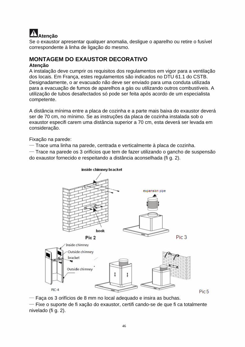
Atenção Se o exaustor apresentar qualquer anomalia, desligue o aparelho ou retire o fusível correspondente à linha de ligação do mesmo. MONTAGEM DO EXAUSTOR DECORATIVO Atenção A instalação deve cumprir os requisitos dos regulamentos em vigor para a ventilação dos locais. Em França, estes regulamentos são indicados no DTU 61.1 do CSTB. Designadamente, o ar evacuado não deve ser enviado para uma conduta utilizada para a evacuação de fumos de aparelhos a gás ou utilizando outros combustíveis. A utilização de tubos desafectados só pode ser feita após acordo de um especialista competente. A distância mínima entre a placa de cozinha e a parte mais baixa do exaustor deverá ser de 70 cm, no mínimo. Se as instruções da placa de cozinha instalada sob o exaustor especifi carem uma distância superior a 70 cm, esta deverá ser levada em consideração. Fixação na parede: — Trace uma linha na parede, centrada e verticalmente à placa de cozinha. — Trace na parede os 3 orifícios que tem de fazer utilizando o gancho de suspensão do exaustor fornecido e respeitando a distância aconselhada (fi g. 2).
— Faça os 3 orifícios de 8 mm no local adequado e insira as buchas. — Fixe o suporte de fi xação do exaustor, certifi cando-se de que fi ca totalmente nivelado (fi g. 2).
47
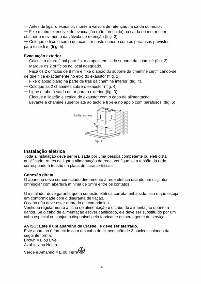
— Antes de ligar o exaustor, monte a válvula de retenção na saída do motor. — Fixe o tubo extensível de evacuação (não fornecido) na saída do motor sem obstruir o movimento da válvula de retenção (fi g. 3). — Coloque e fi xe o corpo do exaustor neste suporte com os parafusos previstos para esse fi m (fi g. 5). Evacuação exterior — Calcule a altura fi nal para fi xar o apoio em U do suporte da chaminé (fi g. 2). — Marque os 2 orifícios no local adequado. — Faça os 2 orifícios de 8 mm e fi xe o apoio do suporte da chaminé certifi cando-se de que fi ca exactamente no eixo do exaustor (fi g. 2). — Fixe o apoio plano na parte de trás da chaminé inferior. (fig. 4). — Coloque as 2 chaminés sobre o exaustor (fi g. 4). — Ligue o tubo à saída de ar para o exterior. (fig. 3). — Efectue a ligação eléctrica do exaustor com o cabo de alimentação. — Levante a chaminé superior até ao tecto e fi xe-a no apoio com parafusos. (fig. 6)
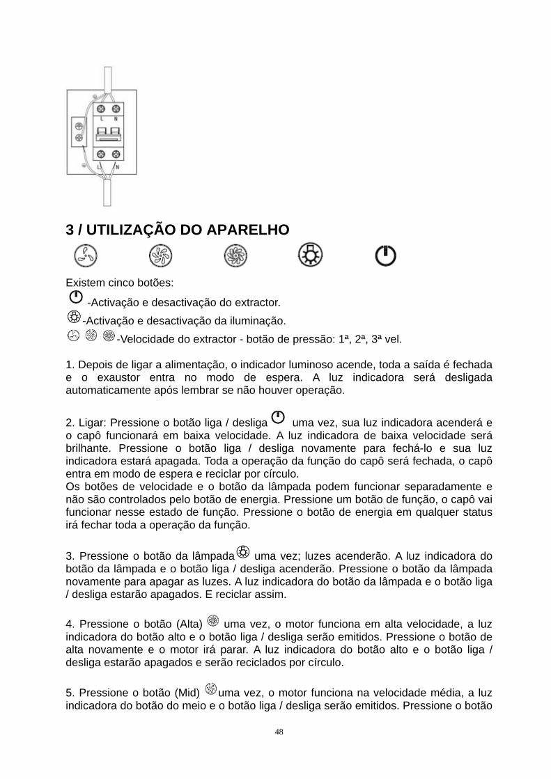
Instalação elétrica Toda a instalação deve ser realizada por uma pessoa competente ou eletricista qualificado. Antes de ligar a alimentação da rede, verifique se a tensão da rede corresponde à tensão na placa de características. Conexão direta O aparelho deve ser conectado diretamente à rede elétrica usando um disjuntor omnipolar com abertura mínima de 3mm entre os contatos. O instalador deve garantir que a conexão elétrica correta tenha sido feita e que esteja em conformidade com o diagrama de fiação. O cabo não deve estar dobrado ou comprimido. Verifique regularmente a ficha de alimentação e o cabo de alimentação quanto a danos. Se o cabo de alimentação estiver danificado, ele deve ser substituído por um cabo especial ou conjunto disponível pelo fabricante ou seu agente de serviço. AVISO: Este é um aparelho de Classe I e deve ser aterrado. Este aparelho é fornecido com um cabo de alimentação de 3 núcleos colorido da seguinte forma: Brown = L ou Live Azul = N ou Neutro
Verde e Amarelo = E ou Terra
48
3 / UTILIZAÇÃO DO APARELHO
Existem cinco botões:
-Activação e desactivação do extractor.
-Activação e desactivação da iluminação.
-Velocidade do extractor - botão de pressão: 1ª, 2ª, 3ª vel. 1. Depois de ligar a alimentação, o indicador luminoso acende, toda a saída é fechada e o exaustor entra no modo de espera. A luz indicadora será desligada automaticamente após lembrar se não houver operação.
2. Ligar: Pressione o botão liga / desliga uma vez, sua luz indicadora acenderá e o capô funcionará em baixa velocidade. A luz indicadora de baixa velocidade será brilhante. Pressione o botão liga / desliga novamente para fechá-lo e sua luz indicadora estará apagada. Toda a operação da função do capô será fechada, o capô entra em modo de espera e reciclar por círculo. Os botões de velocidade e o botão da lâmpada podem funcionar separadamente e não são controlados pelo botão de energia. Pressione um botão de função, o capô vai funcionar nesse estado de função. Pressione o botão de energia em qualquer status irá fechar toda a operação da função.
3. Pressione o botão da lâmpada uma vez; luzes acenderão. A luz indicadora do botão da lâmpada e o botão liga / desliga acenderão. Pressione o botão da lâmpada novamente para apagar as luzes. A luz indicadora do botão da lâmpada e o botão liga / desliga estarão apagados. E reciclar assim.
4. Pressione o botão (Alta) uma vez, o motor funciona em alta velocidade, a luz indicadora do botão alto e o botão liga / desliga serão emitidos. Pressione o botão de alta novamente e o motor irá parar. A luz indicadora do botão alto e o botão liga / desliga estarão apagados e serão reciclados por círculo.
5. Pressione o botão (Mid) uma vez, o motor funciona na velocidade média, a luz indicadora do botão do meio e o botão liga / desliga serão emitidos. Pressione o botão
49
do meio novamente e o motor irá parar. A luz indicadora do botão do meio e o botão liga / desliga estarão apagados e serão reciclados por círculo.
6. Pressione o botão (baixo) uma vez, o motor funciona em baixa velocidade, a luz indicadora do botão baixo e o botão liga / desliga serão emitidos. Pressione o botão de baixa novamente e o motor irá parar. A luz indicadora do botão inferior e do botão liga / desliga serão desativados e reciclados por círculo. 7. Baixa velocidade, velocidade média e alta velocidade não podem funcionar ao mesmo tempo. Quando o capô está em alta velocidade, pressione baixa velocidade, ele irá girar para baixa velocidade de uma só vez; quando estiver em baixa velocidade, pressione a velocidade intermediária, ela girará para a velocidade média imediatamente e assim por diante.
4 / MANUTENÇÃO E LIMPEZA DO APARELHO
Atenção Desligue o aparelho antes de proceder à sua limpeza e manutenção. Uma manutenção periódica do aparelho é uma garantia para o seu devido funcionamento, bom rendimento e durabilidade.
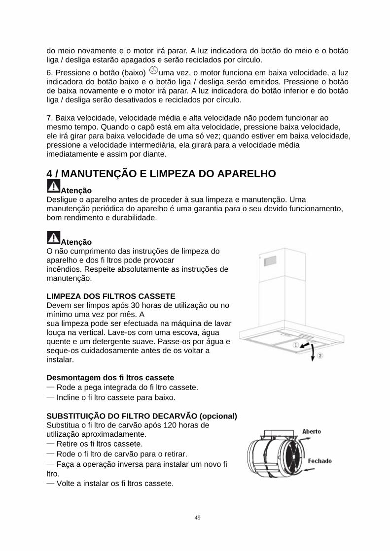
Atenção O não cumprimento das instruções de limpeza do aparelho e dos fi ltros pode provocar incêndios. Respeite absolutamente as instruções de manutenção. LIMPEZA DOS FILTROS CASSETE Devem ser limpos após 30 horas de utilização ou no mínimo uma vez por mês. A sua limpeza pode ser efectuada na máquina de lavar louça na vertical. Lave-os com uma escova, água quente e um detergente suave. Passe-os por água e seque-os cuidadosamente antes de os voltar a instalar. Desmontagem dos fi ltros cassete — Rode a pega integrada do fi ltro cassete. — Incline o fi ltro cassete para baixo. SUBSTITUIÇÃO DO FILTRO DECARVÃO (opcional) Substitua o fi ltro de carvão após 120 horas de utilização aproximadamente. — Retire os fi ltros cassete. — Rode o fi ltro de carvão para o retirar. — Faça a operação inversa para instalar um novo fi ltro. — Volte a instalar os fi ltros cassete.
50
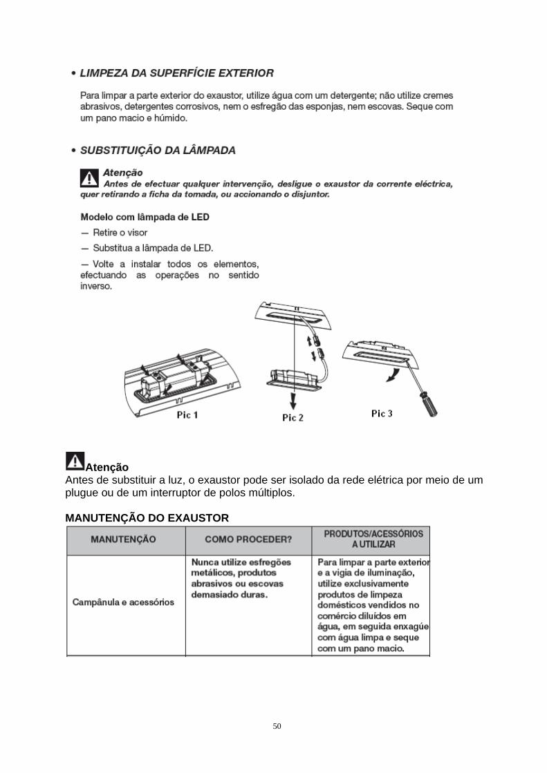
Atenção Antes de substituir a luz, o exaustor pode ser isolado da rede elétrica por meio de um plugue ou de um interruptor de polos múltiplos. MANUTENÇÃO DO EXAUSTOR