Installation Steps Step 1 – Check Equipment and Job Site 6 Step 2 – Inspect Filters and Heat Exchangers 7 Step 3 – Clearance Requirements 8 Step 4 – Install on Solid and Level Foundation 9 Step 5 – Drain Connections 9 Step 6 – Outdoor Intake Air 10 Step 7 – Conditioned Air Ducts 10 Step 8 – Working Air Ducts 12 Step 9 – Water Supply Connections 14 Step 10 – Electrical Power Connection 17 Step 11 – Control Wiring 18 Step 12 – Control Board Set-up and Operation 19 Step 13 – Thermostat 20 Step 14 – HMX Wet Out Logic 20 Step 15 - Operational Startup 21 Step 16 – Final Checks 22
Post Installation / Seasonal Start-up 22 Normal Operating Procedure 23 Seasonal Shutdown 23 Care and Maintenance 23
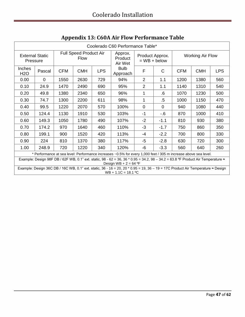
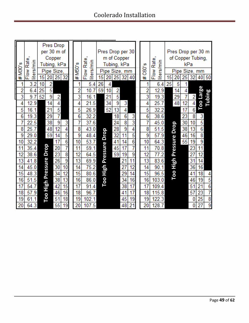
Appendix Appendix 1 – Coolerado Water Quality Requirements 25 Appendix 2 – Control Board and Wiring Diagram 26 Appendix 3 – Water Control Board LED Indicators 28 Appendix 4 – Coolerado Thermostat Wiring Picture 29 Appendix 5 -- Multiple Unit Control Wiring 30 Appendix 6 – Thermostat Operations for (TEC2145-4) 31 Appendix 7 – Freeze Protection 37 Appendix 8 – M50B Dimensional Specifications 39 Appendix 9 – M50 Exhaust Duct Fabrication 41 Appendix 10 – M50B Air Flow Performance Table 42 Appendix 11 – M50B Curb Mount Unit 43 Appendix 12 – C60A Air Dimensional Specifications 44 Appendix 13 – C60A Flow Performance Table 47 Appendix 14 – Water Pressure Charts 48 Appendix 15 – Limited Warranty 50 Appendix 16 – Installation Check List 52 Appendix 17 – Preventative Maintenance, (PM) Checklist 57 Appendix 18 – Cleaning HMX’s 58 Appendix 18 – Troubleshooting 61
Page 4 of 62
Installation Notes
Coolerado Installation
Page 5 of 62
SAFETY CONSIDERATIONS
Improper installation, adjustment, alteration, service, maintenance, or use can cause explosion, fire, electrical shock, or other conditions, which may cause death, personal injury, or property damage.
Use this product only in a manner intended by manufacturer.
Ensure the fan has completely stopped prior to changing filters.
Before servicing or cleaning, other than changing filters, ensure power to the unit is disconnected and locked out.
Keep body, hands, and foreign objects away from air intake while unit is in operation.
To avoid fire hazard, do not block any air intake.
Do not use the unit cabinet as a platform or storage.
Do not attempt to sit, stand, or climb on the unit.
Do not use the unit’s fan with any solid state speed control device.
Consult a qualified installer, service agency, or your product distributor for more information, or assistance. The qualified installer or agency must use only factory-authorized kits or accessories when modifying this product. Refer to the individual instructions packaged with the kits or accessories when installing. WARNING: Follow all safety codes. Wear safety glasses, protective clothing, and work gloves. Read these instructions thoroughly and follow all warnings or cautions included in literature and attached to the unit. These instructions are intended as a general guide and do not supersede local codes in any way. Authorities having jurisdiction should be consulted before installation. Recognize safety information, symbols and words:
(DANGER) will identify serious hazards, which will result in severe personal injury or death.
(CAUTION) will identify unsafe practices, which would result in minor personal injury or poor unit performance, product damage and property damage.
(NOTE) will be used to highlight suggestions, which will result in enhanced installation, reliability, or operation. INSTALLATION RECOMMENDATIONS
NOTE: Any restrictions to air movement, either for intake air, conditioned air, or exhaust air, will reduce the capacity and efficiency of the unit.
NOTE: Working air (exhaust) will always be heavier than ambient air until it fully mixes and comes to equilibrium with outside air.
NOTE: Do not drill, cut, or compromise the powder coat finish within the wet section of the unit. See Figure 19
The unit may be installed either indoors or outdoors. Indoor installations require inlet air duct and working air, (humid air exhaust), duct which may increase costs and often add to static duct pressure loss, create tight working spaces and require flexible connections to allow future maintenance.
Flexible duct connectors should be installed between any rigid ductwork and the unit to allow for leveling requirement and to mitigate vibration. If the unit is mounted indoors, a 2 ft. service area in front of the Coolerado inlet fan plenum for servicing must be designed for. The inlet air duct attached to this plenum will need to be easily removable for maintenance access.
Leave room for maintenance such as filter changing on the C60 requires 25” on at least one side. If the units are hung from the ceiling it can be difficult to change filters.
If unit is installed indoors, install an emergency drain pan that extends beyond the unit by at least 6” (152 mm) on all sides along with separate overflow drain in accordance with local plumbing codes.
Be sure to provide adequate support for the unit and associated ductwork.
Be sure that there is no exposure to flammable vapors, excessive dust, or other contaminants in the air.
To obtain the greatest cooling capacity, air will need to flow into and out of the unit as freely as possible.
Humid working air must be allowed to flow freely away from the unit and directed away from the
Coolerado Installation
Page 6 of 62
unit’s intake air supply. If ducted, ensure adequate condensate drains are available.
The intake air opening must be kept free from obstruction and allowed to draw in fresh dry air.
The conditioned air must be unobstructed to the building or space to be cooled.
All ductwork must be properly sealed and insulated.
Keep all ductwork runs as short as possible between the unit and conditioned space.
If exhaust ducts are needed they must be sealed.
If unit is installed outdoors, install rain shields as needed.
In unheated environments, provide adequate freeze protection for system water supply and drain.
Ensure level mounting to allow the internal water distribution to work correctly.
If the potable water supply is considered moderately hard, hard or very hard include a sodium-based water softener, see Appendix 1.
NOTE: Make any necessary duct modifications to implement seasonal Duct Blocks during initial installation.
It is recommended that off-season duct blocking devices be installed as part of the end-of-season shutdown procedures.
Step 1—Check Equipment and Job Site
CAUTION: Take the necessary precautions and use appropriate equipment to move and install. INSPECT PACKAGING OF EQUIPMENT BEFORE ACCEPTANCE Check the unit for any signs of shipping damage before accepting equipment from the freight carrier. If shipment is damaged do not accept shipment or it may become yours as is. If damaged, file an immediate claim with the shipping company. No return shipment will be accepted without written return authorization. UNPACK UNIT Move to final location. Remove carton or packaging, taking care not to damage unit. INSPECT EQUIPMENT Check the unit for any signs of shipping damage. Fan should spin freely and all covers and parts should be secured
properly. To reduce the shipping footprint on a C60, the conditioned air plenum may be shipped wrapped to the inlet of the unit rather than bolted on. If shipment is damaged or incomplete, file a claim with the shipment company as soon as possible. No return shipment will be accepted without return authorization. NOTE: The unit is shipped with air filters for initial use. CHECK BUILDING UTILITIES AND GEOMETRY
Check for plumbing vent location Check for exhaust vents and fumes from heaters Check water location and hookup Check for location of sanitary sewer drain Check for storm sewer Do downspouts connect to the storm sewer drain? Check power Check control connections Check water hardness
LOCATION OF EQUIPMENT Select a location for the unit as close as possible to the supply air diffuser and away from any building exhaust or sources of high humidity levels.
NOTE: If tying into existing HVAC equipment check for complete functionality before starting any work.
NOTE: Prevailing winds and building geometry must be taken into consideration in determining air inlet and exhaust locations. Additional ductwork for either the intake or exhaust may be required to assure proper separation of the air streams.
Prevailing wind consideration, Figure 1
NOTE: Inlet hoods should not be located near driveways, parking lots, gas meters, oil fill pipes, dryer vents or other
Coolerado Installation
Page 7 of 62
areas. Avoid areas where objectionable vapors, contaminants, or excess particles could be drawn into the unit. Humid working air must be directed into a free air outdoor space and away from any condensing surface.
NOTE: Humidity sources include the Working Air exhausts from the unit itself or from adjacent units, cooling towers, open drains, grass, bushes, trees, swampy areas, swimming pools, water features, plumbing vents, etc.
DANGER: Do not expose the unit intake air to flammable liquids or vapors and away from excessive dust sources. LIFTING EQUIPMENT
Forklift / crane Crane Straps and spreader bar Upper security banding (as seen below)
The lifting point above the unit must be at least 4’ (1.2 m) or a spreader bar is needed to prevent squeezing the box. Care should be taken not to rack or torque the units when moving or lifting units into position as this may cause poor door fitting, Heat and Mass Exchanger racking and leaking, air leaks, etc.
M50C Lifting Lugs, Figure 2
Lifting Straps/Banding, Figure 3
Step 2— Inspect Filters and Heat Exchangers
1.) Inspect the unit’s filters for damage or debris.
2.) Spin the fan for freedom of movement.
3.) Remove filters and inspect heat and mass exchangers (ensure flow arrow on filter is correct).
4.) Inspect surfactant soap container for proper level.
NOTE: Coolerado provides three ply panel filters with about a MERV 8 rating. This is a depth loaded synthetic media that will hold twice the dirt than the pleated filters with the same pressure drop. They also do not allow dirt bypass round the perimeter or between filters, are not affected by water and are about the same cost. We highly recommend replacing filters with panel filters.
DANGER: Do not expose the intake air to flammable liquids or vapors. CAUTION: Do not substitute 2” (50 mm) filter with two 1” (25 mm) filters, this will significantly reduce the airflow through the unit. See Figure 5
Filter image, Figure 5
Step 3—Clearance Requirements
1.) Inspect clearances and position the unit for
installation – see Appendices 8, 10 or 12 for unit dimensions and clearance details per model.
2.) Familiarize yourself with the unit’s connection and service points. See Figure 6.
Exhaust Out Back, (Removable for Duct
Installation)
High Voltage Power Factory Wired Connections
Soap Pump
Control Wiring, Low Voltage
Do Not Block Filter Access Door
Filter Access Door Handles
Lifting Lugs
Drain
Water In
Low Voltage Wire Terminals In
High Voltage Wire Terminals In
Outdoor Air In
Identifying System Components, M50C, Figure 6
NOTE: Ensure unit is positioned so that filters, soap pump and electrical service areas are easily accessible for maintenance and seasonal changes. NOTE: Figure 7 shows the working exhaust air from the top. For units using side working air exhaust. CAUTION: Ensure a minimum of 24” (610 mm) clearance for side mounted working air exhaust. NOTE: Take precautions not to block service areas of unit and that the ductwork connection has enough flexibility for leveling or seasonal re-leveling purposes.
PanelFilter
3-Ply Panel Filter
Coolerado Installation
Page 9 of 62
Clearances:
Sides: 0" if exhausted from the top. 24"(600 mm) if exhausted from both sides. A baffle maybe needed between M50's to reduce mixing with intake air.
Outside Air Intake, fan side: 24" (600 mm).
Conditioned Air Plenum side: 12" (300 mm).
Top: 6" (150 mm) for installation if not exhausting out the top.
Do Not Cut Below 6" (150
mm) From Base of Unit
Clearance Requirements, Figure 7
Step 4— Install on a Solid and Level Foundation
Mount the unit on a solid and level foundation with
proper sub-base and drainage to ensure the unit will not shift during its lifetime.
Take the proper precautions when mounting the unit to reduce noise and vibration.
If mounted on rafters, use appropriately sized vibration damping springs and duct isolation attachments.
If installed on a roof, an attic, or any place where structural support may be an issue, consult with a structural engineer and comply with local code requirements.
If unit is installed indoors, install an emergency drain pan that extends beyond the unit by at least 6” (150 mm) on all sides along with separate overflow drain directed to a sink or outside location where the leak can be seen and in accordance with local plumbing codes, see Figure 9.
Overflow/Drain Example, Figure 9
LEVEL UNIT The weight of the wet unit will require a stable base. During installation, the unit must be properly supported and leveled to stay stable over time. The water delivery to all areas inside the unit depends on the unit being level within 1/16” per foot (5.2 mm/meter) in both directions. CAUTION: Failure to do so will void system warranty.
CAUTION: Foundation racks or solid drainage footing/concrete pads must be used on ground installations to ensure the unit remains level and secure. Proper preparation of ground is necessary to maintain level footing over time.
CAUTION: Do not place unit directly underneath roof, eaves or drip lines without adequate gutters.
Step 5 – Drain Connections
NOTE: The units drain connection is located underneath the unit’s intake air plenum.
Install system drain piping that can be 1 ½” (38.1 mm) pipe over outside; 1 ¼” (31.75 mm) inside or 40mm deeper inside
If local or state codes allow drain water to be used for Irrigation, it must be drained away from the pad to eliminate any settling that will prevent the unit from remaining level. If this occurs, the drain line must slope a minimum of 1/8” per foot (10.4 mm/meter).
Pooling of water near the unit will also allow excess humidity to be drawn into the unit, which will reduce the cooling performance of the unit.
CAUTION: Do not discharge to roof top drains that drain to parking lots or alleys. (The continual flow of water will cause a slick green alga growth).
Coolerado Installation
Page 10 of 62
Drain Connection, Figure 10
If the unit drain line is connected to an internal building sanitary sewer drain line, it must feed into a 1-1/4” (40mm), (or larger) plumbing drain line that meets all plumbing code requirements. The drain line must be vented as it enters the building sanitary sewer drain line.
Step 6—Outdoor Intake Air
NOTE: The intake air duct must not be located near the units working air duct.
Install and inspect ductwork if needed.
The intake air can enter the unit directly or through a properly sized duct. Use intake sizes from Table 1:
Model Intake Duct Size Intake Duct Size
M50 20 inches 500 mm
C60 22 inches, (20” at fan inlet) 560 mm, (508 mm at fan inlet)
Intake Duct Sizes, Table 1
NOTE: If the unit is installed in a building (attic or other) a duct may be needed to draw fresh intake air into the unit from outside the building.
NOTE: The free open area of the intake grill must equal the duct area. Failure to do so may cause excessive pressure drop across the grill, see duct sizes in Table 1.
NOTE: If rigid duct is used to connect to the unit’s intake air, it must be designed to be easily removed to allow service access.
NOTE: In some roof top installations, parapet walls can trap the heavy cool humid working air below the walls causing the intake air to have a high humidity resulting in higher conditioned air temperatures. In these situations, the intake air may need to be brought from a higher location, see Figure 11.
High Parapet Walls, Figure 11
Intake Snorkel, Figure 12
Step 7 –Conditioned Air Duct
1.) Install properly sized, sealed and insulated conditioned, R6 minimum, air duct to unit.
2.) For all units the conditioned air plenum is shipped without pre-cut duct openings. This allows the installer to add the ducts where desired on location. Duct openings should only be cut into the front of the supply plenum. DO NOT CUT OPENING IN THE BOTTOM OF SUPPLY PLENUM or within 2” (20mm) of the bottom. Coat and seal any exposed metal, see Appendices 8, 10 and 12.
NOTE: Seasonal shut off dampers or easily accessible duct blocks should be installed for easy winterization changeover.
Coolerado Installation
Page 11 of 62
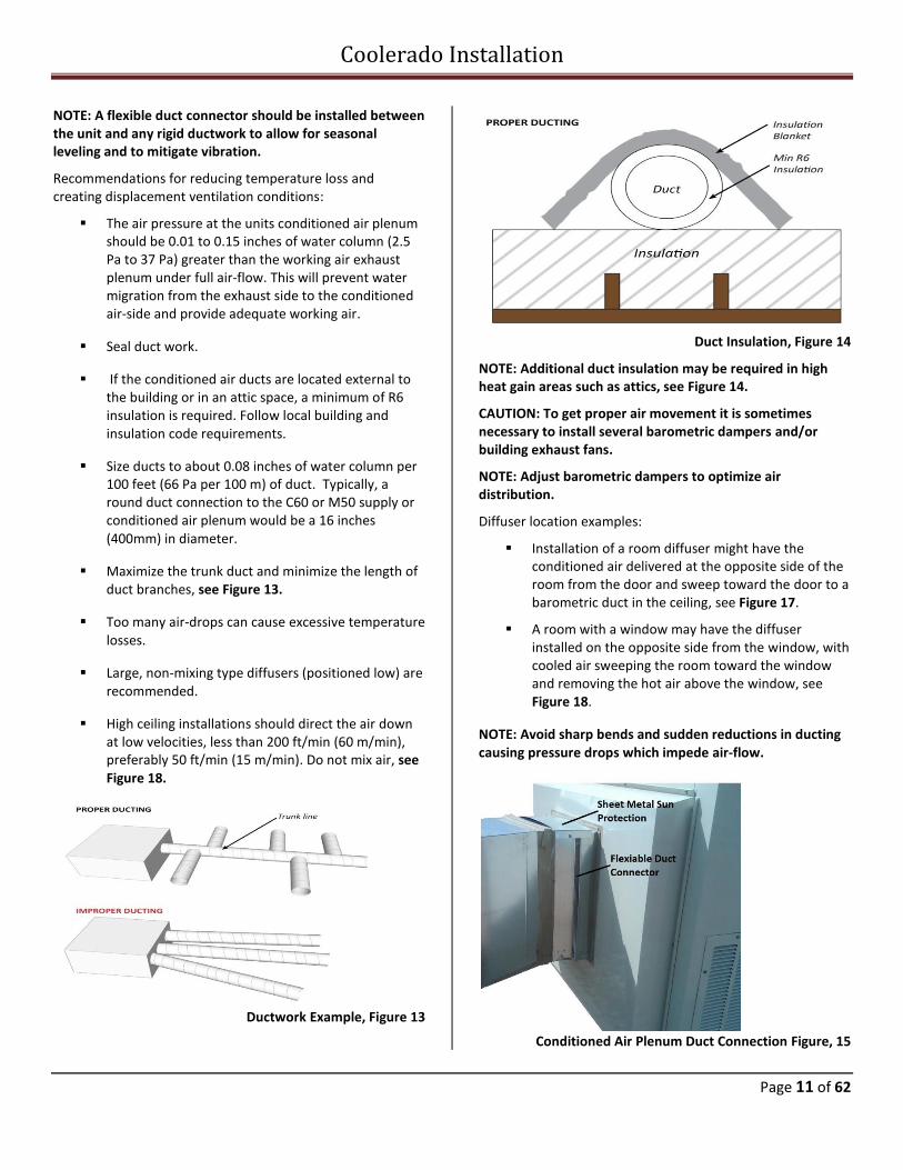
NOTE: A flexible duct connector should be installed between the unit and any rigid ductwork to allow for seasonal leveling and to mitigate vibration.
Recommendations for reducing temperature loss and creating displacement ventilation conditions:
The air pressure at the units conditioned air plenum should be 0.01 to 0.15 inches of water column (2.5 Pa to 37 Pa) greater than the working air exhaust plenum under full air-flow. This will prevent water migration from the exhaust side to the conditioned air-side and provide adequate working air.
Seal duct work.
If the conditioned air ducts are located external to the building or in an attic space, a minimum of R6 insulation is required. Follow local building and insulation code requirements.
Size ducts to about 0.08 inches of water column per 100 feet (66 Pa per 100 m) of duct. Typically, a round duct connection to the C60 or M50 supply or conditioned air plenum would be a 16 inches (400mm) in diameter.
Maximize the trunk duct and minimize the length of duct branches, see Figure 13.
Too many air-drops can cause excessive temperature losses.
Large, non-mixing type diffusers (positioned low) are recommended.
High ceiling installations should direct the air down at low velocities, less than 200 ft/min (60 m/min), preferably 50 ft/min (15 m/min). Do not mix air, see Figure 18.
Ductwork Example, Figure 13
Duct Insulation, Figure 14
NOTE: Additional duct insulation may be required in high heat gain areas such as attics, see Figure 14.
CAUTION: To get proper air movement it is sometimes necessary to install several barometric dampers and/or building exhaust fans.
NOTE: Adjust barometric dampers to optimize air distribution.
Diffuser location examples:
Installation of a room diffuser might have the conditioned air delivered at the opposite side of the room from the door and sweep toward the door to a barometric duct in the ceiling, see Figure 17.
A room with a window may have the diffuser installed on the opposite side from the window, with cooled air sweeping the room toward the window and removing the hot air above the window, see Figure 18.
NOTE: Avoid sharp bends and sudden reductions in ducting causing pressure drops which impede air-flow.
Conditioned Air Plenum Duct Connection Figure, 15
Coolerado Installation
Page 12 of 62
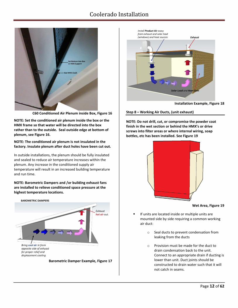
C60 Conditioned Air Plenum inside Box, Figure 16
NOTE: Set the conditioned air plenum inside the box or the HMX frame so that water will be directed into the box rather than to the outside. Seal outside edge at bottom of plenum, see Figure 16.
NOTE: The conditioned air plenum is not insulated in the factory. Insulate plenum after duct holes have been cut out.
In outside installations, the plenum should be fully insulated and sealed to reduce air temperature increases within the plenum. Any increase in the conditioned supply air temperature will result in an increased building temperature and run time.
NOTE: Barometric Dampers and /or building exhaust fans are installed to relieve conditioned space pressure at the highest temperature locations.
Barometric Damper Example, Figure 17
Installation Example, Figure 18
Step 8 – Working Air Ducts, (unit exhaust)
NOTE: Do not drill, cut, or compromise the powder coat finish in the wet section or behind the HMX’s or drive screws into filter areas or where internal wiring, soap bottles, etc has been installed. See Figure 19
Wet Area, Figure 19
If units are located inside or multiple units are mounted side by side requiring a common working air duct:
o Seal ducts to prevent condensation from leaking from the ducts
o Provision must be made for the duct to drain condensation back to the unit. Connect to an appropriate drain if ducting is lower than unit. Duct joints should be constructed to drain water such that it will not catch in seams.
Coolerado Installation
Page 13 of 62
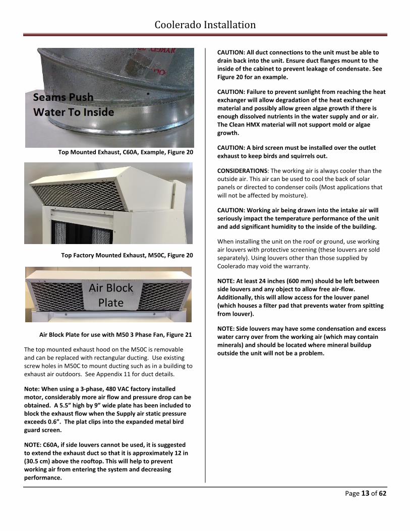
Top Mounted Exhaust, C60A, Example, Figure 20
Top Factory Mounted Exhaust, M50C, Figure 20
Air Block Plate
Air Block Plate for use with M50 3 Phase Fan, Figure 21
The top mounted exhaust hood on the M50C is removable and can be replaced with rectangular ducting. Use existing screw holes in M50C to mount ducting such as in a building to exhaust air outdoors. See Appendix 11 for duct details.
Note: When using a 3-phase, 480 VAC factory installed motor, considerably more air flow and pressure drop can be obtained. A 5.5” high by 9” wide plate has been included to block the exhaust flow when the Supply air static pressure exceeds 0.6”. The plat clips into the expanded metal bird guard screen.
NOTE: C60A, if side louvers cannot be used, it is suggested to extend the exhaust duct so that it is approximately 12 in (30.5 cm) above the rooftop. This will help to prevent working air from entering the system and decreasing performance.
CAUTION: All duct connections to the unit must be able to drain back into the unit. Ensure duct flanges mount to the inside of the cabinet to prevent leakage of condensate. See Figure 20 for an example.
CAUTION: Failure to prevent sunlight from reaching the heat exchanger will allow degradation of the heat exchanger material and possibly allow green algae growth if there is enough dissolved nutrients in the water supply and or air. The Clean HMX material will not support mold or algae growth.
CAUTION: A bird screen must be installed over the outlet exhaust to keep birds and squirrels out.
CONSIDERATIONS: The working air is always cooler than the outside air. This air can be used to cool the back of solar panels or directed to condenser coils (Most applications that will not be affected by moisture).
CAUTION: Working air being drawn into the intake air will seriously impact the temperature performance of the unit and add significant humidity to the inside of the building.
When installing the unit on the roof or ground, use working air louvers with protective screening (these louvers are sold separately). Using louvers other than those supplied by Coolerado may void the warranty.
NOTE: At least 24 inches (600 mm) should be left between side louvers and any object to allow free air-flow. Additionally, this will allow access for the louver panel (which houses a filter pad that prevents water from spitting from louver).
NOTE: Side louvers may have some condensation and excess water carry over from the working air (which may contain minerals) and should be located where mineral buildup outside the unit will not be a problem.
Coolerado Installation
Page 14 of 62
Exhaust Louvers, Figure 22
C60A units are shipped with precut holes for louvers.
NOTE: two (2) side louvers are required for C60A’s to prevent spiting from the side of the unit.
CAUTION: The working air expels excess water, minerals and salts at all times it is in operation. Any holes cut into this section or screws attached must be coated on the inside with a high quality duct sealer to prevent corrosion. In most cases the HMX’s will need to be removed to adequately seal any punctures to the inside of the working air section and prevent rusting of the box. This may void warranty if not properly sealed.
Side Cover and Louver Attachment:
To seal the side covers or louver very little torque is needed
to tighten the screws. Over tightening will cause warping of
the cover or louver. Eight (8) 10 – 32 stainless steel screws
are used to hold the louvers or covers on. The unit comes
with matching blind rivets mounted in the box.
Inside Cover, Figure 23
Step 9 – Water Supply Connections
Note: Do not turn water on unit till Step 15.
See Appendix 14 for line size and pressure charts.
CAUTION: Clean potable water should be connected to the
Coolerado air conditioner, see Appendix 1 Coolerado Water
Quality Requirements for more details.
CAUTION; Do Not use galvanized or black iron piping
anywhere in the water supply system.
Water lines should be insulated from heat sources such as the sun to prevent overheating and scaling of the water. If the water line insulation will see sun light at any point it should be UV protected material. When hard water is heated, it increases its scaling potential such as in a water heater.
NOTE: When choosing to insulate exposed water lines, UV protection must be accounted for. If using non-UV rated insulation, it is suggested to coat the insulation with a weatherproofing finishing paint or jacket.
The instantaneous water flow rate to the HMX’s is the water required when turned on by the water control board. The water is turned off most of the time. A clean and consistent water supply capable of instantaneous 85 GPH (gallons per hour) (322 LPH(liters per hour)) for a M50, and 102 GPH (386 LPH) for a C60, for proper operation of the units.
NOTE: Install a hose bib at the main water line near the unit. This will allow for quicker and easier servicing as well its double use for cleaning the units.
It is also suggested to install ½ in. ball valves to the main water line of the unit if installing multiple. This will allow individual units to be shut off during maintenance rather than shutting all units off.
The water connection is a ½” (12.7 mm) FNPT at the unit base. The water pressure at this connection must be between 40 psi (225 kPa) and 80 psi (550 kPa). For your convenience, Appendix 14 provides water pressure drop information. Note that the water pressure will decrease 1 psi for every 27.7” (9.8 kPa for every 1 m) of height do to gravity. So for a 30’ (9.14 m) rise, the water pressure will decrease by 13 psi (90 kPa), this does not include pressure drop due to friction in the piping and pipe fittings.
Note: A Water Pressure Switch has been installed on the water line inside the unit that will disconnect the fan control
Coolerado Installation
Page 15 of 62
wire turning the fan off until the water pressure rises again, see Figure 25. This means a dirty water filter or low water main pressure will turn the fan off. If the main water pressure is low a, booster pump may be required.
CAUTION: Dynamic water supply pressure of between 25 PSI (172 kPa) and 80 PSI (550 kPa) is required at the unit.
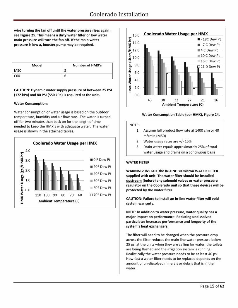
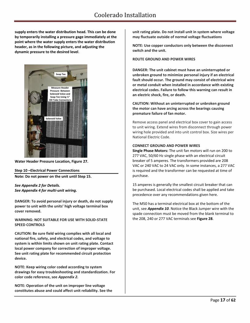
Water Consumption:
Water consumption or water usage is based on the outdoor temperature, humidity and air flow rate. The water is turned off for two minutes than back on for the length of time needed to keep the HMX’s with adequate water. The water usage is shown in the attached tables.
Water Consumption Table (per HMX), Figure 24.
WATER FILTER
WARNING: INSTALL the IN-LINE 30 micron WATER FILTER supplied with unit. The water filter should be installed upstream (before) any solenoid valves or water pressure regulator on the Coolerado unit so that these devices will be protected by the water filter.
CAUTION: Failure to install an in-line water filter will void system warranty.
NOTE: In addition to water pressure, water quality has a major impact on performance. Reducing undissolved particulates increases performance and longevity of the system’s heat exchangers.
The filter will need to be changed when the pressure drop across the filter reduces the main line water pressure below 25 psi at the units when they are calling for water, the toilets are being flushed and the irrigation system is running. Realistically the water pressure needs to be at least 40 psi. How fast a water filter needs to be replaced depends on the amount of un-dissolved minerals or debris that is in the water.
0.0
1.0
2.0
3.0
4.0
110 100 90 80 70 60
HM
X W
ate
r U
sage
(ga
l/H
MX
-hr)
Ambient Temperature (F)
Coolerado Water Usage per HMX
0 F Dew Pt
20F Dew Pt
40F Dew Pt
50F Dew Pt
60F Dew Pt
70F Dew Pt
0.0
2.0
4.0
6.0
8.0
10.0
12.0
14.0
16.0
43 38 32 27 21 16
HM
XW
ate
r U
sage
(Li
ters
/HM
X-h
r)
Ambient Temperature (C)
Coolerado Water Usage per HMX- 18C Dew Pt
- 7 C Dew Pt
4 C Dew Pt
10 C Dew Pt
16 C Dew Pt
21 D Dew PtModel Number of HMX’s
M50 5
C60 6
NOTE:
1. Assume full product flow rate at 1400 cfm or 40
m3/min (M50)
2. Water usage rates are +/- 15%
3. Drain water equals approximately 25% of total
water usage and drains on a continuous basis
Coolerado Installation
Page 16 of 62
NOTE: If incoming water pressure is more than 80 psig (550 kPa), a pressure-reducing valve should be installed to the incoming water supply line.
WATER PRESSURE REQUIREMENTS
NOTE: If incoming water pressure is ever less than 25 psig (172 kPa) when the unit is running, a water pressure booster pump may be required. District water line pressures are often decreased due to irrigation activities, especially at night. A minimum building pressure is generally 40 psi to maintain the pressure at the unit of 25 psi when considering water filter pressure drop, perhaps a water softener, toilets being flushed, the units may be mounted on the roof causing pressure loss due to gravity and height, and the irrigation system running.
Low Water Pressure: In certain locations, a reduction or potential loss of water pressure can occur due to high demand conditions on the municipal or district water supply. Install a booster pump to ensure water pressure is maintained. If required, mount booster equipment near ground level, see Figure 25.
Check Valve, CV
Booster Pump
Pressure Tank
Pressure Gauge
Union
Relief Valve
Pressure Sensor
Circuit BreakerDisconnect (110VAC, 20 amp)
Control for Booster PumpNeed 25 psi (172 kPa)
Minimum at Coolerado Unit
By Contractor:
CV
Main Water Line Hose Bib
Ball Valve
Water Booster, Hose Bib, and Ball Valve, Figure 25.
NOTE: Use a minimum of 1/2” (12.7 mm) diameter supply water line, which should be free draining for winter shut down.
BACK FLOW PREVENTION
NOTE: The unit is equipped with a self-draining water regulating valve designed with a vacuum break in the HMX.
Water Distribution System – M50C, Figure 26
Freeze protection can be done manually:
1.) Install supply water shut off valve between the water supply line and the unit.
2.) Install a drainage valve downstream of the manual water valve. The drain valve should be located within a conditioned space.
3.) Slope the line from the unit to the drain valve for proper draining and freeze protection.
4.) To drain the line and water distribution system it must be turned on for a few minutes to allow the water to drain and air to pulled into the system. This is done by turning the thermostat to require a cool call.
WATER DISTRIBUTION SYSTEM The water distribution system, (located inside the unit) is a combination pressure regulator, 24 VAC solenoid valve and water distributions manifold. The valve is designed to deliverer the correct water flow to each of the systems heat exchangers.
NOTE: Water Distribution System pressure should be adjusted in the field to 5.4 inches of water column. The adjustment must be made in the field to adjust for elevation above sea level.
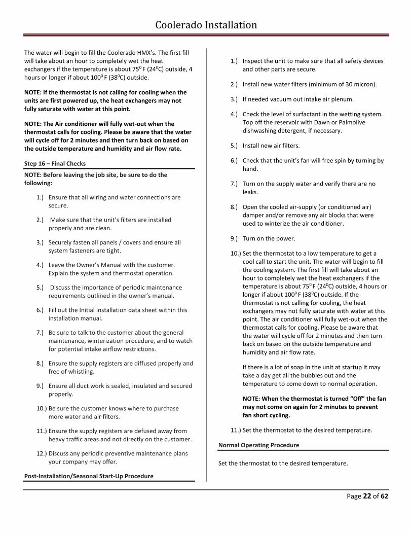
CAUTION: It is absolutely essential that the pressure regulator be set to deliver the proper pressure at the water distribution head before installation can be considered complete. For the most accurate setting possible, take a dynamic pressure reading at the point where the water
Coolerado Installation
Page 17 of 62
supply enters the water distribution head. This can be done by temporarily installing a pressure gage immediately at the point where the water supply enters the water distribution header, as in the following picture, and adjusting the dynamic pressure to the desired level.
Water Header Pressure Location, Figure 27.
Step 10 –Electrical Power Connections
Note: Do not power on the unit until Step 15.
See Appendix 2 for Details. See Appendix 4 for multi-unit wiring.
DANGER: To avoid personal injury or death, do not supply power to unit with the units’ high voltage terminal box cover removed.
WARNING: NOT SUITABLE FOR USE WITH SOLID-STATE SPEED CONTROLS
CAUTION: Be sure field wiring complies with all local and national fire, safety, and electrical codes, and voltage to system is within limits shown on unit rating plate. Contact local power company for correction of improper voltage. See unit rating plate for recommended circuit protection device.
NOTE: Keep wiring color coded according to system drawings for easy troubleshooting and standardization. For color code reference, see Appendix 2.
NOTE: Operation of the unit on improper line voltage constitutes abuse and could affect unit reliability. See the
unit rating plate. Do not install unit in system where voltage may fluctuate outside of normal voltage fluctuations
NOTE: Use copper conductors only between the disconnect switch and the unit.
ROUTE GROUND AND POWER WIRES
DANGER: The unit cabinet must have an uninterrupted or unbroken ground to minimize personal injury if an electrical fault should occur. The ground may consist of electrical wire or metal conduit when installed in accordance with existing electrical codes. Failure to follow this warning can result in an electric shock, fire, or death.
CAUTION: Without an uninterrupted or unbroken ground the motor can have arcing across the bearings causing premature failure of fan motor.
Remove access panel and electrical box cover to gain access to unit wiring. Extend wires from disconnect through power wiring hole provided and into unit control box. Size wires per National Electric Code.
CONNECT GROUND AND POWER WIRES Single Phase Motors: The unit fan motors will run on 200 to 277 VAC, 50/60 Hz single phase with an electrical circuit breaker of 5 amperes. The transformers provided are 208 VAC or 240 VAC to 24 VAC only. In some instances, a 277 VAC is required and the transformer can be requested at time of purchase.
15 amperes is generally the smallest circuit breaker that can be purchased. Local electrical codes shall be applied and take precedence over any recommendations given here.
The M50 has a terminal electrical box at the bottom of the unit, see Appendix 10. Notice the Black Jumper wire with the spade connection must be moved from the blank terminal to the 208, 240 or 277 VAC terminals see Figure 28.
Measure Header Pressure Between Solenoid Valve and Soap Tee Using ½”
OD Tube Connectors
Solenoid Valve
Soap Tee
Coolerado Installation
Page 18 of 62
1~ Electrical Power Connections, Figure 28
Three Phase Motors; 480 VAC, 50/60 Hz with an electrical
circuit breaker of 10 amperes each leg.
3~ Electrical Power Connections, Figure 29
CAUTION: The transformer was not designed to power other
equipment.
NOTE: The electrical access panels have screw holes to fit
most electrical box covers making it easy to install switches,
outlets, etc.
CAUTION: Line Voltage and Control wires must be routed clear of any system components such as filter access doors to prevent wiring chafing / electrical shorts.
CAUTION: Ensure line and control voltage wires are routed away from terminal connections and control board.
Step 11 – Control Wiring
Note: Do not start unit till Step 15. See Appendix 2 for wiring instructions.
CONTROL REQUIREMENTS
Input Cool Call “Y” (1st stage cooling call)
Variable Speed Fan, 0-10 VDC signal or no signal and full speed; dipswitch 7 OFF
Winter/Summer mode; if fan to be used in winter
Freeze Protection relay; if needed
NOTE: The water control board provides 24 VAC (via terminal RC) to be switched thru a dry contact back to terminal Y.
Eight Pin plug in Cable Connector on water control
board and wired to a wire terminal block
1. Y – Cool Call dry contact
2. RC - 24 VAC
3. Variable Speed Fan controlled by 0-10 vdc
4. Common
5. Winter/Summer; winter mode when contact
closed. Allows fan to run without water
pressure. It initiates Freeze Protection relay,
this turns off the main water line, (if connected
to a solenoid valves), opens the water drain
line, and opens up the unit water solenoid valve
for 5 minutes. Closed contact or Winter mode
takes precedence over Winter/Summer Switch
on the Water Control Board. White light comes
on.
6. 24 VAC
7. Freeze protection relay.
8. Common
Control Terminal, Figure 30
Coolerado Installation
Page 19 of 62
If using the recommended variable control thermostat model TEC3620:
Unit Control Thermostat TEC3620 Color
Y-24 VAC IN FAN Yellow
RC-24 VAC OUT 24V Red
Variable Fan CGL Blue
COM COM Black
Thermostat Connections, Table 2
Step 12 – Control Board Set-up and Operation
Note: Do not start unit till Step 15.
CONTROL BOARD 8 DIP SWITCHES
1. Initiates the Wet Out cycle after a power failure
with two possible settings, OFF over one hour,
ON over four hours.
2. Low and High water quantity, OFF plus 25%, ON
plus 50% over the calculated evaporation rate.
3. Model Number, in conjunction with 4; factory
setting.
4. Model Number
5. Elevation, in conjunction with 6.
6. Elevation
7. Auto Variable Fan, OFF 10 vdc, ON from AIN
8. Freeze Protection, OFF no freeze protection, ON
freeze protection, (requires connection to
solenoid valves by others).
If a variable speed thermostat is used, set control dip switch setting 7 to the “on” position. This will vary the water flow based on the amount of air flow. If dip switch 7 is set in the off position, 10 VAC will be delivered to the fan motor control wiring and it will run full speed whenever cooling is called for.
Dip switch setting 8 controls if freeze protection is on or off, see appendix 8 for additional installation details. Freeze protection allows the unit to be automatically pulled out of service during a cold spell but keep the unit ready for cooling. It should not be used for end of season shut down when cooling is no longer needed for an extended period of time. In some locations cooling is required all year round but still may experience temperatures below 32oF and require temporary shutdown to prevent breakage of valves or line. Freezing will not harm HMX.
Dip switch
1 Power Failure Rewet; OFF less than 1 Hour, ON 4 Hour 2 Water Quality, OFF good, ON poor
3 Model Number, Factory Set
4 Model Number, Factory Set
Elevation
0 2000’ (610M) 4000’ (1220M)
6000’ (1830M)
5 Off On Off On
6 Off Off On On
7 On for Variable Speed Fan, 0 to 10 VDC OFF = Single Speed Fan Setting (10 VAC)
8 On Freeze Protection mode see Appendix 8
Table 3: Control Board Dip Switch Settings
Control Operation
See Appendix 2, 3, 4 and 5 for more information.
There are five (5) LED’s on the control board to indicate:
Power on: Green LED light
Water solenoid is powered: Clear light
Cool call: Yellow light
Flush cycle is on: Red light
Winter /summer: White light
The water control board has a fan speed potentiometer, (see appendix 2). This is a single turn pot that controls the maximum voltage going to the fan. If dip switch 7 is in the off position the fan voltage can be turned between 0 and 10 VDC. If dip switch 7 is on, then this pot will proportionally vary the voltage received at the water control board allowing a maximum fan speed to be set. The factor setting is full speed.
Note: If a three-speed fan is used the fan speed potentiometer mentioned directly above may need to be used to reduce fan speed, see appendix 10.
The water control board also has three switches mounted on it for ease of maintenance, (see appendix 2):
1. WINTER switch allows the fan to be operated through the cool call and AV fan but with the water off. Putting in winter mode will also cause it to go into freeze protection. The terminal connection precedence over the board winter switch.
2. WETOUT momentary switch allows a maintenance person to start a wet out cycle as long as there is a
Coolerado Installation
Page 20 of 62
Cool Call. A jumper across the Y and RC terminals will cause a Cool Call.
3. PRIME momentary switch allows a maintenance person to prime the soap pump by pushing it and holding it till primed.
Step 13 – Thermostat
Note: Do not start unit till Step 15.
A standard thermostat can be used however most thermostats do not have 0 to 10 VDC capabilities to drive the Coolerado fully auto variable fan. For this reason, Coolerado sells a variable speed thermostat.
NOTE: The efficiency of the Coolerado goes up significantly as the speed is reduced, (4x at half speed), so variable speed control is encouraged when possible.
NOTE: The thermostat should be mounted on an interior building wall, free of drafts, and in an area unaffected by heat producing machinery or appliances.
See Appendix 5, Thermostat Operation. For additional information on the thermostat see Appendix 2, Control Board and Wiring Diagram; Appendix 4, Coolerado Thermostat Wiring; Appendix 5, Multiple Unit Control Wiring and Appendix 6, Thermostat operation.
Step 14 – HMX Wet Out Logic
Note: Do not start unit till Step 15.
The unit is equipped with an automatic wetting system that provides a significant boost to the heat and mass exchangers wetting operations when the unit is powered up at initial installation, for seasonal restart, or any other time that the heat exchangers have dried out after the power has been shut off.
Water and Soap System, Figure 31
The system consists of a small pump, a surfactant (soap) reservoir, and a manual override switch located on the water control board. Units are shipped from the factory with an empty reservoir but separately a full bottle of surfactant solution. This is to prevent soap being spilled into the unit during transportation. To start up the system the pump and tubing will need to be primed with wetting solution at installation; prime switch on water control board.
The pump is controlled by the water control board, and is engaged any time the unit is powered up after an extended powered off time and there is a cool call. The pump and surfactant lines must be primed full of surfactant before the system is started for wetting heat and mass exchangers. The pump will operate as long as the override primer switch on the water control board called “PRIME” is held down.
To assist in manual, startup of unit there is also a “WETOUT” button on the water control board that when pushed will start a wet out cycle.
To allow the unit to be operated over the winter months without water the “WINTER” switch can be activated. The winter mode can also be activated through control wiring and it will take precedence.
When filters are changed, top off the reservoir with Dawn™ or Palmolive™ liquid dishwashing detergent.
NOTE: At installation or at any time that the unit has been dried out, such as after winterization or vacation shut-off, it is imperative to add a surfactant to the water supply to allow the air conditioner heat exchangers to fully wet out.
After the heat exchangers have been wet out, water will distribute itself evenly until the heat exchangers are dried due to the water being turned off, or power being turned off for an extended period of time.
A capacitor has been included on the water control board to keep an internal clock going with a power failure. The unit is then able to know how long a power failure has been and can
Soap Pump Water Control BoardTransformer
Solenoid Valve, Pressure Regulator
and Pressure Switch
Soap Bottle
Coolerado Installation
Page 21 of 62
start up without a rewetting of the HMX’s if the time has been less than one hour if dipswitch 1 is OFF or 4 hours if ON.
When the unit power is turned on after an extended off time, (greater than one hour if dipswitch 1 is OFF or four hours if ON), and a cooling call is made from the thermostat, the water control board has been programmed to engage the fan, solenoid valve, and the surfactant pump. After 2.5 minutes the water and surfactant will be turned off for 10 minutes. The water control board will then cycle the water on for 30 seconds and off for 2 minutes for 2 additional cycles with soap. This 30 second on and 2 minute off will then be repeated and additional 5 times without soap.
The water control will then be regulated according to outside temperature, humidity, dynamic water pressure at the unit (water flow), as well as the fan speed and control settings.
Check outlet temperature after 2 hours of system operation. If the conditioned air temperature (dry bulb) is within 3oF, (-16oC), of the inlet wet bulb temperature, no other action is needed.
NOTE: If there is excessive soap in the unit at start up, it may take a day to dispense all bubbles and the temperature to come down to normal operation.
If the conditioned air temperature (dry bulb) is more than 3oF, (-16oC), above the inlet wet bulb, manually turn the water off and switch to winter mode and let unit run for 20 to 45 minutes depending on the outside temperature, (hotter shorter time), to let the HMX’s dry out. Switch back to summer mode to allow the wetting process to start over. Because of the partially wet HMX’s and recent wetting out there may be a lot of bubbles.
During normal operation, when the thermostat gives a cooling call it will activate the water control board. The fan and the water cycle will start immediately. The water will go off for 2 minutes after initial wetting that is dependent on the temperature and humidity then cycle as needed 2 minutes off and on as needed.
Without a cooling call for a period of 1 hour, the water control board will douse the heat exchanger with fresh water to ensure the heat exchanger remains saturated. The water will cycle on for 2 minutes, then off for an hour starting a new cycle.
Step 15 – Operational Startup
1.) For C60 turn the fan switch on the top front of the unit off. The M50A fan will shut down when the filter cover is removed.
2.) Remove all electrical and soap pump cover plates 3.) Turn off the cool call or disconnect the cool call by:
a. C60 disconnecting the wire at the RC terminal on the terminal strip to the left of the water control board as seen standing in front of the unit, (not the transformer connections R and C terminals).
b. M50 disconnecting the wire at the RC terminal in the low voltage junction box at the bottom of the unit.
4.) Power up the unit. 5.) Prime the soap pump by pressing the button on the
water control baord, see Appendix 2. Soap should be just entering the T in the line before the header).
6.) Turn on the water and check for leaks at the solenoid valve connections.
7.) Create a “cool call” by closing contacts across terminals RC and Y on the water control board and check for leaks; (do not deliver voltage to Coolerado Water Control Board Y and RC terminals) .
8.) With the water pressure gage mounted between the header and the solenoid valve, adjust the water pressure according to Table 2, see Figure 27.
9.) Reinstall the air filters. 10.) Install the filter cover door. 11.) On the C60 Turn on the fan switch. 12.) Replace cool call wiring for normal operation. 13.) Install covers over soap pump and low voltage
electrical box. 14.) Adjust thermostat set point below room
temperature to call for cooling. 15.) After initial wetting period (approx. 1 hour), inspect
for system cooling operations. 16.) Inspect supply diffusers for excess noise or whistling. 17.) Inspect for vibration or abnormal noise. 18.) The supply or product air stream static pressure
should be higher than the working air or exhaust air stream by about 0.01 to 0.5 inches of water column (2.5 Pa to 125 kPa). This helps to prevent water from leaking from the working air side to the product side. These pressures should be taken very near to the exhaust plenum and the product plenum at points that are at 90 degrees to the direction of air flow. This will require a small hole in the product duct and exhaust duct. If side exhaust louvers are used, (no exhaust duct), with even small product side pressure the exhaust pressure should be less.
19.) Check supply dynamic water pressure to the units and record, (between 25 and 85 psi) (between 172 and 586 kPa).
Coolerado Installation
Page 22 of 62
The water will begin to fill the Coolerado HMX’s. The first fill will take about an hour to completely wet the heat exchangers if the temperature is about 750 F (240C) outside, 4 hours or longer if about 1000 F (380C) outside.
NOTE: If the thermostat is not calling for cooling when the units are first powered up, the heat exchangers may not fully saturate with water at this point.
NOTE: The Air conditioner will fully wet-out when the thermostat calls for cooling. Please be aware that the water will cycle off for 2 minutes and then turn back on based on the outside temperature and humidity and air flow rate.
Step 16 – Final Checks
NOTE: Before leaving the job site, be sure to do the following:
1.) Ensure that all wiring and water connections are secure.
2.) Make sure that the unit’s filters are installed properly and are clean.
3.) Securely fasten all panels / covers and ensure all system fasteners are tight.
4.) Leave the Owner’s Manual with the customer. Explain the system and thermostat operation.
5.) Discuss the importance of periodic maintenance requirements outlined in the owner’s manual.
6.) Fill out the Initial Installation data sheet within this installation manual.
7.) Be sure to talk to the customer about the general maintenance, winterization procedure, and to watch for potential intake airflow restrictions.
8.) Ensure the supply registers are diffused properly and free of whistling.
9.) Ensure all duct work is sealed, insulated and secured properly.
10.) Be sure the customer knows where to purchase more water and air filters.
11.) Ensure the supply registers are defused away from heavy traffic areas and not directly on the customer.
12.) Discuss any periodic preventive maintenance plans your company may offer.
Post-Installation/Seasonal Start-Up Procedure
1.) Inspect the unit to make sure that all safety devices
and other parts are secure.
2.) Install new water filters (minimum of 30 micron).
3.) If needed vacuum out intake air plenum.
4.) Check the level of surfactant in the wetting system. Top off the reservoir with Dawn or Palmolive dishwashing detergent, if necessary.
5.) Install new air filters.
6.) Check that the unit’s fan will free spin by turning by hand.
7.) Turn on the supply water and verify there are no leaks.
8.) Open the cooled air-supply (or conditioned air) damper and/or remove any air blocks that were used to winterize the air conditioner.
9.) Turn on the power.
10.) Set the thermostat to a low temperature to get a cool call to start the unit. The water will begin to fill the cooling system. The first fill will take about an hour to completely wet the heat exchangers if the temperature is about 750 F (240C) outside, 4 hours or longer if about 1000 F (380C) outside. If the thermostat is not calling for cooling, the heat exchangers may not fully saturate with water at this point. The air conditioner will fully wet-out when the thermostat calls for cooling. Please be aware that the water will cycle off for 2 minutes and then turn back on based on the outside temperature and humidity and air flow rate.
If there is a lot of soap in the unit at startup it may take a day get all the bubbles out and the temperature to come down to normal operation.
NOTE: When the thermostat is turned “Off” the fan may not come on again for 2 minutes to prevent fan short cycling.
11.) Set the thermostat to the desired temperature.
Normal Operating Procedure
Set the thermostat to the desired temperature.
Coolerado Installation
Page 23 of 62
In cooling mode, the thermostat will control the fan and the water supply. Outside air is drawn through the fan, filtered, cooled, and then delivered to the building. The cooled air is delivered via standard air distribution ductwork to the structure.
If the unit is located in a high-dust or high-contaminant area, examine the air filters at least monthly and replace as necessary.
Note: Do not dry heat exchangers at night by running the blower using only cool night air. Doing so on a daily basis will allow mineral deposits to build-up and void the HMX warranty.
Seasonal Shut Down (regions where winter cooling is not needed)
Note: If there is a possibility of freezing weather an automated freeze protection system should be installed.
NOTE: Failure to follow the following seasonal shut down procedures may result in reduced performance to the heat exchangers and may cause equipment damage.
1.) Inspect the unit to make sure that all safety devices and other parts are secure.
2.) Turn the manual water supply valve off upstream of the pressure regulator/solenoid valve assembly.
3.) Open the water supply line drain valve at the T and drain off water in line. The water distribution valve and water supply line will drain down to the T.
4.) Close the supply duct dampers and/or install off-season duct blocking devices. The HMX’s will dry themselves out in several days.
5.) Turn the thermostat to a temperature lower than the room temperature for about 15 minutes so that the water control solenoid valve will open and allow all the water to drain.
6.) Turn off power to the unit.
7.) Close off the barometric damper for the winter according to the manufacturer’s/contractor’s instructions.
8.) Drain water filter housing if mounted outdoors.
9.) Set the thermostat to “heating” or to the “Off” position.
Care and Maintenance Procedure, (see also Appendix 18)
For continuing high performance, and to minimize possible equipment failure, periodic maintenance must be performed on this equipment. Frequency of maintenance may vary de-pending upon geographic areas, such as high dust, pollen or air pollution. Pay close attention to cleanliness of the unit’s filters and heat exchangers. CAUTION: Failure to follow these instructions will shorten the life of your heat exchanger and result in poor performance of your system.
Fan Maintenance Inspect all fan parts including air intake, blades, motor and shroud as well as for free movement. Check for the accumulation of material on the impeller surfaces, which could cause imbalance, resulting in vibration, excess noise, and premature bearing wear. Clean as needed.
The inspection frequency is determined by the severity of the application and local conditions. Strict adherence to an inspection schedule is essential.
Water System Maintenance
Water delivery supply pressure and HMX header pressure should be checked annually.
Check the water supply system for leaks, and repair if needed. Any leaks should be repaired immediately to assure proper water delivery to the unit. With the air filters removed, check the internal tubes of the water distribution system for leaks. Proper and consistent water flow is essential for efficient and proper unit operation.
Water overflowing from the top of the drain pan may indicate that the drain is partially plugged. If this is the case, remove the connection from the bottom of the drain pan and clean.
Check water filter pressure drop and change if over 3 psi (21 kPa).
Heat Exchangers
Each heat exchanger should be visually inspected when the air filters are replaced. If any debris is found it should be removed. If the heat exchangers appear to be damaged in any way contact your service contractor.
Air Filters
The C60A requires four (4) 2” x 16” x 25” (50 mm x 400 mm x 625 mm) pleated filters.
Coolerado Installation
Page 24 of 62
The M50 requires three (3) 2” x 20” x 25” (50 mm x 500 mm x 625 mm) pleated filters.
One (1) 1” (25 mm) thick filter can be used in place of a 2” (50 mm) filters.
Caution: Do not use two (2) 1” (25 mm) filters in series as the pressure drop will be too high.
The filters should be changed regularly to ensure proper airflow through the system. If the system is located in an area where there are higher levels of airborne debris such as pollen, leaves, dust or insects, in which case the filters should be inspected more often.
Inspect the filters periodically during the cooling season and replace with new filters as required.
M50B Filter Changing Procedure:
1.) Remove the filter access cover on the front of the unit above the air inlet with the T-handles.
2.) Slide the top filter all the way to the top of the filter frame. Pull the bottom of the filter towards the fan and drop the filter until the top of the filter clears the M50 cabinet. Lift the filter out of the unit.
3.) The middle and bottom filters can now be lifted up and out of the filter frame.
4.) Reverse this process to re-install the filters. 5.) Re-install the filter access cover.
Side Mounted Working Air Exhaust Louvers: If side louvers are installed, inspect the inside pad that prevents water droplets blowing through the louvers. This should be checked and replaced if filled with minerals. These pads are used in some direct evaporative cooling units for water distribution and are generally green in color.
C60A Filter Changing Procedure:
1.) Turn off the toggle switch located in the top left of the unit on the front face and wait until the fan has come to a stop.
2.) Remove the filter access cover on either side of the unit.
3.) Slide the four (4) filters out the side. 4.) Re-install the filter access cover and turn the fan
control switch on. Outdoor Air Temperature and Humidity Sensor Filter
This filter is located behind the water control board and can
be accessed by removing the Filter Access Door, the top air
filter and reaching up behind the electrical box directly
behind the water control board, see figure 32. This can be
removed with a 7/16” deep socket or wrench.
Outdoor Air Temperature - Humidity Sensor Filter, Figure 32
Temp - Humidity
Sensor
Filtered Outdoor Air Delivered Behind Sensor
Compressed Air Muffler used as Air Secondary Filter for Sensor
Coolerado Installation
Page 25 of 62
Appendix 1: Coolerado Water Quality Requirements
Water quality can be difficult to quantify as there are different factors that must be considered. To ensure proper performance of
the Heat and Mass Exchangers (HMXs), prolong the life of equipment components and to avoid increased maintenance, the below
water criteria must be considered and evaluated before installation.
Solids: All water supplies have the potential to have un-dissolved solids from water line repairs, additions and maintenance. Solids
in the water supply must be filtered out when above 30 microns to prevent plugging of the water distribution system or Heat and
Mass Exchangers (HMXs). Coolerado supplies 30 micron water filters with each unit. Installation of the Coolerado supplied 30 micron
filter or equivalent is required on all installations to filter un-dissolved solids.
Organics: Coolerado’s HMX plate material is manufactured with polypropylene that is not a food source for molds; the plate
material also has a biocide impregnated into it to prevent organics from growing. Typically, the biocide supplied from a potable
water supply district will be enough to prevent any mold growth. However, if supply water that does not contain biocides is being
used, like well water, both the air and maybe the water will have organics that can sustain molds, generally in the form of a slime
that can grow in the water distribution system and on the wet portion of the HMX plate surface. In these cases, a biocide such as
chlorine may be required.
Temperature: When water is heated, dissolved minerals like calcium will come out of solution and form scale—the reason hot water
heaters and pipes build up scale. For this reason, we recommend water supply pipes to the Coolerado units be kept in cool places or
insulated when exposed to the sun.
Dissolved minerals: There are a lot of dissolved minerals in water. However, we are most concerned with the hardness of water
made up mostly of calcium but can include magnesium. Hard water causes two problems. The first is it prevents soap from creating
suds and leaves soap scum on sinks, etc. The second, and maybe bigger problem for any evaporative equipment, is the formation of
scaling most generally in the form of calcium carbonate (the magnesium will stay in solution under much higher concentrations).
Calcium carbonate can close off water lines, collapse cooling towers from the weight of scale build up, and—in general—cause many
problems. The key here is the amount of calcium water hardness. A low quantity of hard water is not a problem.
How hard water is generally defined as:
Classification Hardness in mg/L or PPM
Soft 0 – 60
Moderately Hard 61 – 120
Hard 121 – 180
Very Hard > 180
Water that is Moderately Hard or greater should be treated with a sodium or potassium based water softener.
Coolerado cannot know the details of your water supply and therefore how the water will react with our water delivery system.
The water should be tested to properly address any water quality concerns, contact your local water utility to determine the total
harness of your water or have the water tested at a water laboratory.
Coolerado Installation
Page 26 of 62
Appendix 2: Control Board and Wiring Diagrams
Water, Elevation and Fan Control Dip Switches
Auto Variable Fan Control, 0 to 10 VDC
RC provides 24 VAC for dry contact to Y with Cool Call Operates
Water Solenoid
0 to 10 VDC to Fan speed control
Surfactant Pump control
24 VAC power supply from transformer
Fan Speed Potentiometer, turn clockwise for full speed.
Water Control Board LED Indicators WINTER Winter/Summer operation, (Winter water is turned off).
FLUSH Adds water to HMX when no cool call for more than an hour
COOL Cool Call
Water Water On
POWER Power is on
X LED is ON
B LED is Blinking
LED is OFF
WINTER FLUSH COOL WATER POWER Meaning
No POWER to the board
X Power to board, summer mode, fan is off
B Problem with the control board’s integrated temperature/humidity
sensor and the board must be replaced
X X Power is on, summer mode, there is a cool call and fan is on
X X X Power is on, summer mode, cool call, water is on an fan is on
X X X Power is on, summer mode, flush cycle, water is on and fan is off
X X Power is on, summer mode, flush cycle, water is off and fan is off
X X Power is on, winter mode and fan is off
X X X Power is on, winter mode, cool call (or air flow call) and fan is on
Coolerado Installation
Page 29 of 62
Appendix 4: Coolerado Thermostat Wiring
Johnson Controls
TEC3620
Thermostat
Feed Control Wires
Through Knockout
FAN L
To
Y-24 AVC IN
24V
To
RC-24 VAC
OUT
COM
To
COM
CLG
To
Variable Fan
1-10 VDC
Note: The C60 terminal strip
is located to the left of the
water control board.
Coolerado Low
Voltage Terminal
Strip
Coolerado Installation
Page 30 of 62
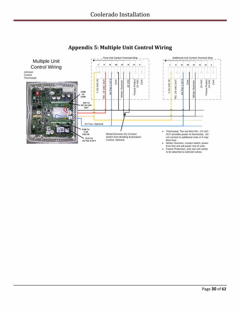
Appendix 5: Multiple Unit Control Wiring
CLG To
AV Fan 2-10 V
Co
m
AV
Fa
n 1
-10
V
Y-2
4 V
AC
IN
RC
- 2
4 V
AC
OU
T
Win
ter
/Su
mm
er
24
VA
C
Fre
eze
Pro
tect
24
VA
C
Co
m
Y R Br Bk Bl W Or G
Co
m
AV
Fa
n 1
-10
V
Y-2
4 V
AC
IN
RC
- 2
4 V
AC
OU
T
Win
ter
/Su
mm
er
24
VA
C
Fre
eze
Pro
tect
24
VA
C
Co
m
Y R Br Bk Bl W Or G
FAN To
Y-24
VAC IN
24V To
RC-24 VAC
OUT
COM
To
COM
First Unit Control Terminal Strip Additional Unit Control Terminal Strip
Multiple Unit
Control Wiring
· Thermostat, The red Wire RC– 24 VAC
OUT provides power to thermostat. Do
not connect to additional units or it may
blow fuse.
· Winter /Summer, contact switch; power
from first unit will power rest of units.
· Freeze Protection, only one unit needs
to be attached to solenoid valves.
AV Fan, Optional
Winter/Summer Dry Contact
Switch from Building Automation
Control, Optional.
Johnson
Control
Thermostat
Coolerado Installation
Page 31 of 62
Appendix 6: Thermostat Operation (TEC3620)
Note: The Johnson Control TEC3620 has been adapted to work with the Coolerado Water Control Board and
variable speed fan motor. The Water Control Board requires a 24 VAC for cool call and is taken from the FAN
terminal. The Variable Speed Motor requires a 2 to 10 VDC control voltage and is taken from the CLG
terminal.
Front Cover of Thermostat
There are many options and scheduling modes that are available with this thermostat. See Johnson Controls “TEC300 Series Proportional Fan Coil and Zoning Thermostat Controllers with Dehumidification Capability, Installation Instructions” for full instructions
There are several settings that must be used to operate the Coolerado Equipment and have been factory set:
1) Under Display Settings / Show Fan Icon: must be “No” as this is used as a cool call not fan setting. The Fan Icon allows three settings that will cause the unit not to operate as expected.
Coolerado Installation
Page 32 of 62
2) Under Equipment Setup / General / Unit Type: must be “4-Pipe”. This allows use of CLG 2 to 10 VDC control signal to vary the fan speed. This is generally used to control a hydronic valve opening.
3) Under Equipment Setup / General / Valve Open Voltage: must be “10 VDC”. This gives maximum speed of Fan
4) Under Equipment Setup / General / Valve Closed Voltage: must be “2 VDC”. This gives minimum speed of Fan
5) Under Equipment Setup / General / Supply Fan / Supply Fan Type: must be “Single Speed”. Because the supply Fan terminals are used as a cool call this gives a simple 24 VAC control voltage to the water control board.
6) Under Equipment Setup / Changeover /Changeover Mode: must be “Cooling”. This prevents change over to heating that is not compatible in the Coolerado unit. It is not possible to have a separate heating system as the Coolerado uses the Single Speed Fan terminal as a cool call.
7) Under System Status / Zone Temp Source: must be “Internal Sensor” unless external sensors are purchased and used.
Level 1 Level 2
(LCD Screen Name)
Level 3
(Default Values)
Available Values
Setpoints Occ Cooling Setpoint 72°F (22°C) 55 to 85°F (13 to 30°C)
Occ Heating Setpoint 68°F (20°C) 55 to 85°F (13 to 30°C)
Unocc Cooling Setpoint 80ºF (27°C) 55 to 85°F (13 to 30°C)
Unocc Heating Setpoint 60°F (15°C) 55 to 85°F (13 to 30°C)
Stby Cooling Setpoint 74°F (23°C) 55 to 85°F (13 to 30°C)
Stby Heating Setpoint 66°F (19°C) 55 to 85°F (13 to 30°C)
Humidity Setpoint* 50% RH 0 to 100% RH
*Dehumidification Enable = True
Schedule Schedule Options
Optimal Start Enable No Yes or No
Temp Occ Duration 120 minutes 0 to 300 minutes
Motion Sensor Timeout 15 minutes 15 to 240 minutes
Manual Occupancy Mode* No Override No Override, Occupied, Unoccupied
Schedule Source Local Local or BAS
Level 1 Level 2
(LCD Screen Name)
Level 3
(Default Values)
Available Values
Display Settings Passcode Enable No Yes or No
Passcode* NA 0000 to 9999
*Passcode Enable = Yes
Brightness Setting 8 0 to 10 (most dim to brightest)
Enable Backlight Timeout Yes Yes or No
Units IP IP or SI
Coolerado Installation
Page 33 of 62
Time N/A Time Zone Central Many options
Set Time Format 24 hour 24 hour or 12 hour
Date N/A Set Date Format YYYY-MM-DD YYYY-MM-DD, or Day, Month DD, YYYY,
or MM-DD-YYYY
Show Fan Icon No Yes or No
Show Temp Yes Yes or No
Show Humidity Yes Yes or No
Show Off Icon Yes Yes or No
Show Hold Icon Yes Yes or No
Show Setpoint Yes Yes or No
Show Alarms Yes Yes or No
Show Occ Status Yes Yes or No
Show Unit Status Yes Yes or No
Show Date/Time Yes Yes or No
Level 1 Level 2
(LCD Screen Name)
Level 3
(Default Values)
Available Values
Control Setup General
Control Mode Cooling Auto, Cooling, or Heating
Unit Enable Enable Enable or Shutdown
Fan Mode* Auto Not Used, On, Auto, Smart
* Fan Coil units only
Max Setpoint Offset 3 degrees 0 to 20 degrees (F or C based on Units setting under Display Settings menu)
Fan On Delay* 30 seconds 0 to 120 seconds
* Fan coil units only
Fan Off Delay* 30 seconds 0 to 120 seconds
* Fan coil units only
Frost Protection No Yes or No
Reset PID Tuning* No Yes or No
Auto PID Tuning Enable Yes Yes or No
Dehumidification Enable* No Yes or No
Aux Mode Not Used Not Used, Occupied NO, Occupied NC, Occupied Fan NO, Occupied Fan NC, On, Off
Inputs
BI1 Config Disabled Disabled, Occupancy, Occupancy Override, Remote PIR, Dirty Filter, Service, Fan Lock, Open Door, Open Window
BI2 Config Disabled Disabled, Occupancy, Occupancy Override, Remote PIR, Dirty Filter, Service, Fan Lock, Open Door, Open Window
System Status Occupancy Source Local Schedule Occupancy BI
Temp Occ BI
Temp Occ
Occ Override
Local Schedule
BAS Schedule
Occupancy Sensor
Unit Status Cooling System Fault
Airflow Fault
Open Window
Control Off
Unreliable Temperature
Dehumidification
Idle
Cooling
Heating
Cooling Unavailable
Heating Unavailable
Cooling Unavailable due to Changeover
Cooling Unavailable due to OA Temp
Cooling Unavailable due to Control Mode
Heating Unavailable due to Changeover
Heating Unavailable due to OA Temp
Heating Unavailable due to Control Mode
Supply Air Temperature 75°F -50 to 250°F (-45 to 121°C)
Coolerado Installation
Page 36 of 62
Changeover State Changeover Disabled
Cooling Mode
Heating Mode
Supply Temperature Unreliable
Zone Temp Source Internal Sensor
Unreliable
Internal Sensor
Remote Sensor
Network Override
Input Not Installed
Control Status Cooling % Command 0% 0 to 100%
Heating % Command 0% 0 to 100%
Reheat % Command 0% 0 to 100%
Cool Stage 1 Off On or Off
Heat Stage 1 Off On or Off
Reheat Stage 1 Off On or Off
Fan % Command 0% 0 to 100%
Fan On On or Off
Controller Info Model Name TEC3620-00 –
Software Version 1.0.0.1067 –
Unit Name TECxxxxx –
Level 1 Level 2
(LCD Screen Name)
Level 3
(Default Values)
Available Values
Commissioning Supply Air Temperature Display Current Temperature
–
Heat Command 0% 0 to 100%
Cool Command 0% 0 to 100%
Supply Fan No Yes or No
Aux No Yes or No
Update View Version 1.0.0.1067 Current Release of Software
Load Firmware Attempting to access USB
File List from USB drive
Restore Local Storage File List from USB drive1
Backup Saving Backup Configuration Locally
File List from USB drive1
Coolerado Installation
Page 37 of 62
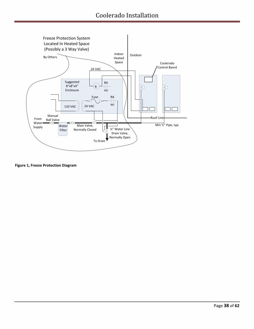
Appendix 7: Freeze Protection
Freeze Protection The Coolerado freeze protection provides the electronic controls needed to disable the cool call from the space-mounted thermostat, if there is a cool call, and drain the water supply lines in the event that the outdoor air temperature falls below 40o F. The Freeze Protection wiring, water solenoid valves, relays, transformers and electrical box are supplied by others, see Figure 1.
Logic
· When the outdoor air temperature, (temperature as sensed by the Coolerado Water Control Board temperature sensor based on the inlet air to the Coolerado unit), drops below 40oF, the Coolerado Water Control Board will no longer allow a cool call to turn the supply fan on. This prevents drying out of the unit’s heat and mass exchangers (HMXs) when the water is turned off for freeze protection.
· In addition, when the temperature drops below 40oF (4.4oC) for a period of 5 minutes or longer, the water control board will break the 24 VAC signal being sent from terminals "2" and "C". This actuates a relay which closes the Main Water Supply Solenoid Valve, (supplied by others), and opens the water line Drain Water Solenoid Valve, (supplied by others). During normal operation, when the outdoor temperature is above 40oF (4.4oC), the water control board output is 24 VAC. When the outdoor temperature falls below 40oF (4.4oC), or during a power failure, there will be no power on terminals "2" and "C".
· When the temperature drops below 36oF (2.2oC) for a period of 5 minutes or longer, the Coolerado water distribution solenoid valve will open for 2 minutes. This allows air to be drawn into the Coolerado water distribution solenoid valve and water line. It is important to have the Coolerado solenoid valve closed until the Main Water Supply Solenoid Valve has been closed or the water will run freely.
· If there are multiple Coolerado Air Conditioners on the same water line and interconnected together on the same thermostat only one unit needs to be connected to valves. All of the Coolerado units will need to have their respective Water Control Boards programmed for freeze protection by turning dipswitch 8 on in order to turn off their respective supply fans at 40oF (4.4oC) and open the Coolerado water distribution solenoid valve at 36oF (2.2oC).
Main Water Supply Solenoid Valve and Drain Solenoid Valve:
The water supply solenoid valve is normally closed and the drain solenoid valve is normally open. In the event of a power failure the supply valve will not open. If there were a leak in the supply valve the drain valve would be open to keep the line from filling. The main water supply solenoid valve must be at least as large as the supply line in order to reduce the pressure loss through the supply valve. Refer to the water pressure chart in Appendix 1 in the Installation Manual for sizing of the water lines and solenoid valves.
The HMXs are not damaged by freezing as the water distribution system in them drains every time the water is turned off at the unit. Water freezing in the HMXs will not damage the plate material. Additionally, the HMXs have an air gap internally that prevents back flow of water. However, the water line, pressure switch, pressure regulator and solenoid valve must be drained to prevent damage. Failure to properly slope the water supply lines towards the drain solenoid valve so they will drain to a heated space that is not subject to freezing temperatures could void the warranty on the Coolerado unit, see figure 1.
Coolerado Installation
Page 38 of 62
Main Valve, Normally Closed
½” Water Line Drain Valve,
Normally Open
110 VAC 24 VAC
To Drain
Freeze Protection System Located In Heated Space(Possibly a 3 Way Valve)
Manual Ball Valve
OutdoorIndoor Heated Space
Min ½” Pipe, typ.
Roof Line
NO
NO
R
RA
RA
24 VAC
Coolerado Control Baord
Suggested 8"x8"x4" Enclosure
Fuse
By Others
Water Filter
From Water Supply
Figure 1, Freeze Protection Diagram
Coolerado Installation
Page 39 of 62
Appendix 8: M50C Dimensional Specifications
Coolerado Installation
Page 40 of 62
Dry Weight: 370 lb, (168 kg) Wet Weight: 420 lb, (191 kg)
Coolerado Installation
Page 41 of 62
Appendix 9: M50C Exhaust Duct Fabrication
Coolerado Installation
Page 42 of 62
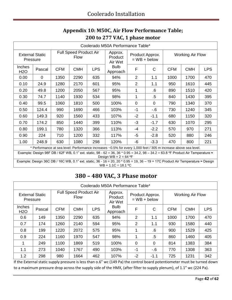
Appendix 10: M50C, Air Flow Performance Table;
200 to 277 VAC, 1 phase motor
Coolerado M50A Performance Table*
External Static Pressure
Full Speed Product Air Flow
Approx. Product Air Wet
Bulb Approach
Product Approx. = WB + below
Working Air Flow
Inches H2O
Pascal CFM CMH LPS F C CFM CMH LPS
0.00 0 1350 2290 635 94% 2 1.1 1000 1700 470
0.10 24.9 1280 2170 601 95% 2 1.1 950 1610 445
0.20 49.8 1200 2050 567 95% 1 .6 890 1510 420
0.30 74.7 1140 1930 534 98% 1 .5 840 1430 395
0.40 99.5 1060 1810 500 100% 0 0 790 1340 370
0.50 124.4 990 1690 466 103% -1 -.6 730 1240 345
0.60 149.3 920 1560 433 107% -2 -1.1 680 1150 320
0.70 174.2 850 1440 399 110% -3 -1.7 630 1070 295
0.80 199.1 780 1320 366 113% -4 -2.2 570 970 271
0.90 224 710 1200 332 117% -5 -2.8 520 880 246
1.00 248.9 630 1080 298 120% -6 -3.3 470 800 221
* Performance at sea level: Performance increases ~0.5% for every 1,000 feet / 305 m increase above sea level.
Appendix 14: Water Pressure Charts Pipe sizes for water delivery to the unit must take into account water pressure loss. The Coolerado system requires a minimum of 25
psi (172 kPa) at each unit to have adequate water distribution. Water pressure can vary dramatically from day to night due to
irrigation, municipal demand, or other events. This makes it difficult to determine the water pressure that will be available for use.
For this reason, it is best to reduce the water pressure losses through the piping, valves, and fittings. To assist in selecting pipe sizes
please consult the tables below.
NOTE: Higher pressure drops are not recommended but rather are shown to help understand the significance of larger pipe sizes.
NOTE: For every 2.3’ (0.7 m) of height above where the water is measured, there is 6 psi (41 kPa) decrease in pressure due to
Coolerado® (“Coolerado”) makes the following LIMITED WARRANTY with respect to its air conditioners and energy recovery ventilators (the “Products”):
· Patented HMXs (Heat-Mass Exchangers) for a period of three (3) years from the date of installation, or three (3) years plus six (6) months from shipment date from Coolerado, whichever results in a shorter warranty period.
· All Other parts for a period of one (1) year from the date of installation, or (1) one year plus six (6) months from shipment date from Coolerado, whichever results in a shorter warranty period.
Coolerado warrants to the original buyer (“Buyer”) of its Products, subject to the conditions and exclusions set forth below, that the Products will be free from defects in material and workmanship (the “Limited Warranty”).
Coolerado’s sole obligation under this Limited Warranty (i) is subject to Coolerado receiving proper notification from Buyer, via Coolerado’s website at www.coolerado.com or sent via U.S. mail to Coolerado, ATTN: Limited Warranty Claims, 4430 Glencoe Street, Denver, Colorado 80216, stating in detail the defect of the Product and the claim made under the Limited Warranty and (ii) is solely limited to repair or replacement by Coolerado, at its option, of any Product determined by Coolerado, in its sole discretion, to be defective. Buyer must notify Coolerado in accordance with this paragraph at least sixty (60) days before pursuing any legal rights or remedies available to Buyer.
Buyer shall be responsible for and shall pay shipping costs to and from Coolerado (FOB factory) for such Product, and/or for the shipping of defective parts to and from Coolerado (FOB factory), for inspection and determination of warranty eligibility.
Coolerado’s Limited Warranty does not cover defects, reduced performance, or failures, caused directly or indirectly, by improper installation, inadequate or excessive water pressure, hard water greater than 60 ppm total hardness that is not adequately treated by a sodium-based water softener or other adequate water treatment as referenced in the Coolerado Water Quality Requirements in the owner’s manual, frequent power outages, abuse, misuse, misapplication, improper maintenance, lack of maintenance, negligence, accident, weather damage, damage related to shipping or handling, or normal deterioration, including wear and tear. The Limited Warranty also shall not apply to failures, defects, or reduced performance resulting, directly or indirectly, from use of the Product for any purpose other than indirect air-cooling, or from exposure to corrosive gases, liquids or other materials. If the Product is installed in conjunction with cabinets, grilles, louvers, controls, other air condition or air handling equipment, or any other parts or equipment not manufactured or provided by Coolerado, this warranty covers only the Coolerado Product.
The following specifically void the Limited Warranty: 1. Weather damage; 2. Improper installation, including inadequate sealing of the unit that exposes the unit’s interior to outside elements; 3. Installation, disassembly, or repairs not performed by a licensed installation contractor or technician, or that do not follow the owner’s
manual or installation manual or do not comply with industry standards or applicable building codes; 4. Inadequate or excessive water pressure to the Product; 5. Power source interruptions, other than intermittent (5-10 minutes) and occasional (i.e. not more than once or twice per cooling season)
interruptions; 6. Air and water filters not being cleaned or replaced as specified in the owner’s manual; 7. Use of hard water greater than 60 ppm total hardness without adequate treatment (see Coolerado’s Water Quality Requirements); 8. Equipment being run with missing or damaged parts, including air or water filters; or 9. Other maintenance, including start-up and winterization, not being performed as specified in the owner’s manual.
This Limited Warranty does not include costs for transportation (including, without limitation, freight and return freight charges, costs and insurance), costs for removal or re-installation of parts or equipment, premiums for overtime, or labor for performing repairs or replacement in the field. Coolerado is not responsible for damages occurring during transport of any Product to or from Coolerado. Coolerado is not obligated to provide field service or labor, such as service for inspection, repairing, removing, or packing, Coolerado product for transportation.
Coolerado reserves the right to charge for handling, inspection and other services in the case of parts or equipment improperly returned as defective and/or as being covered under warranty.
THE OBLIGATION AND LIABILITY OF COOLERADO, AND BUYER’S SOLE AND EXLUSIVE REMEDIES, ARE AS EXPRESSLY STATED. BUYER IS NOT ENTITLED TO ANY OTHER RIGHTS OR REMEDIES AS A RESULT OF THIS LIMITED WARRANTY, INCLUDING WITHOUT LIMITATION, RIGHTS TO RECOVER FOR LOSSES, DIRECT, INDIRECT, INCIDENTAL, SPECIAL, PUNITIVE OR CONSEQUENTIAL DAMAGES. THIS LIMITED WARRANTY IS PROVIDED EXCLUSIVELY TO THE ORIGINAL BUYER OF PRODUCTS AND MAY NOT BE ASSIGNED OR OTHERWISE TRANSFERRED.
THIS LIMITED WARRANTY IS IN LIEU OF ALL OTHER WARRANTIES, EXPRESS OR IMPLIED, INCLUDING WARRANTIES OF MERCHANTABILITY AND FITNESS FOR A PARTICULAR PURPOSE, AND THERE ARE NO WARRANTIES WHATSOEVER WHICH EXTEND BEYOND THE DESCRIPTION ON THE FACE HEREOF. ALL OTHER WARRANTIES IN NON-UNITED STATES JURISDICTIONS ARE DISCLAIMED TO THE MAXIMUM EXTENT PERMITTED BY LAW, UNLESS EXPRESSLY STATED OTHERWISE.
NO PERSON (INCLUDING ANY AGENT, SALES REPRESENTATIVE, DEALER OR DISTRIBUTOR) HAS THE AUTHORITY TO EXPAND COOLERADO’S OBLIGATION BEYOND THE TERM OF THIS LIMITED WARRANTY OR TO STATE THAT THE PERFORMANCE OF THE PRODUCT IS OTHER THAN THAT PUBLISHED BY COOLERADO.
Read the Coolerado Installation Manual Ensure that all electrical meets code requirements Ensure that water supply meets with Coolerado quality requirements
Installation Checklist
1. Is the site clear of any environmental factors that could contaminate supply air? See Step 1 in
Installation Manual □ Yes □ No
2. Does the fan rotate freely? See Step 1 in Installation Manual □ Yes □ No
3. Are proper, factory shipped air filters installed? See Step 2 in Installation Manual □ Yes □ No
4. Are the unit clearances adequate for service and operation? See Step 3 in Installation Manual □ Yes □ No
5. Is the unit level to within Coolerado specifications? See Step 4 in Installation Manual □ Yes □ No
6. Is water being drained away from the unit per local/state plumbing code? See Step 4 in
Installation Manual □ Yes □ No
7. If unit is installed indoors, is a drain pan installed under the unit? See Step 4 in Installation Manual □ Yes □ No
8. Has the unit drain line been connected? See Step 5 in Installation Manual □ Yes □ No
9. What is being used to exhaust working air? See Step 8 in Installation Manual □ Duct Work
□ Louvers
10. If exhausting working air through duct work, does ducting slope enough to allow
condensation to drain back? See Step 8 in Installation Manual □ Yes □ No
Coolerado Installation
Page 53 of 62
Installation Checklist
11. Have product air ducts been insulated and properly sealed? See Step 8 in Installation Manual □ Yes □ No
12. Has product air plenum been insulated and properly sealed? See Step 8 in Installation Manual □ Yes □ No
13. Is water connected and the field water piping to the unit appears to be correct per design
specifications? See Step 9 in Installation Manual □ Yes □ No
14. What is building dynamic water pressure? See Step 9 in Installation Manual psi
15. Is a 30 micron cartridge filter installed on the water supply line? See Step 9 in Installation Manual □ Yes □ No
16. Have all electrical connections been tested for tightness? See Step 10 in Installation Manual □ Yes □ No
17. Does the electrical service correspond to the unit nameplate? See Step 10 in Installation Manual □ Yes □ No
18. What is the voltage to the unit? See Step 10 in Installation Manual Volts
19. Is water turned on? See Step 15 in Installation Manual □ Yes □ No
Post Installation Checklist
1. Are dip switch settings properly set per table? See Step 12 in Installation Manual
Dip switch
1 Power Failure Rewet; OFF< 1 Hr, ON 4
2 Water Quality, OFF good, ON poor
3 Model Number, factory set
4 Model Number, factory set
Elevation
0 2000’(610M) 4000’(1220M) 6000’(1830M)
5 Off On Off On
6 Off Off On On
7 On for Variable Speed Fan
8 On Freeze Protection mode see Appendix 8
□ Yes □ No
2. What is the dynamic water pressure (psig) at the HMX header? See Step 9 in Installation Manual
Is it set at 5.4 inches of water column?
psig
□ Yes □ No
Coolerado Installation
Page 54 of 62
3. What is the dynamic water pressure (psig) to the unit between 25 and 80 psi (172 and 552
kPa) See Step 9 in Installation Manual
psig
4. Are any visible leaks from water supply, drain line and/or unit? See Step 9 in Installation Manual □ Yes □ No
5. Is working air mixing with product air? See Step 15 in Installation Manual □ Yes □ No
6. Has client been informed of and can perform all winterization procedures? See Step 16 in
Installation Manual □ Yes □ No
7. Have copies of all Coolerado documentation and warranty been provided to customer? See
Step 16 in Installation Manual □ Yes □ No
Performance Verification
Static Pressure Performance5
PA1 Static Pressure (WC4) WA2 Static Pressure
(WC4)
PA – WA3 Static Pressure
(WC4)
Meets Pressure
Specification
□ Yes □ No
1 – Product Air
2 – Working Air
3 – Value should be positive number near 0.1” wc
4 – Water Column
5 – Value of 0-2” WC magnehelic gage or equal recommended
Coolerado Installation
Page 55 of 62
Temperature Performance4
Inlet DB1 Temp (oF) Inlet WB2 Temp (oF) PA3 DB Temp(oF) PA DB temp – Inlet WB Temp (oF)
1 – Dry bulb
2 – Wet bulb
3 – Product Air
4 – Digital thermometer used to get within + or – 0.2oF (0.1o C)
WAa
WAb
PA reading
Depending on
how the unit is
setup, you’ll
take WA
readings at the
top of the unit
(a) if ducts are
installed or at
the bottom if
louvers are
installed (b)
Coolerado Installation
Page 56 of 62
PA DB
reading
taken approx
2’ from the
rear of the
unit
DB and WB
readings
Coolerado Installation
Page 57 of 62
Appendix 17: Preventative Maintenance, (PM) Checklist Building: __________________________ Unit Model and Serial # _______________________________
Monthly PM Checklist Please initial & date upon completion of each checked item.
Component JAN FEB MAR APR MAY JUN JUL AUG SEP OCT NOV DEC
Air Filter
* Check & change if needed
* 2”x20”x25” pleated (50x500x625mm)
* MERV 8 or better air filter
Surfactant
* Check operation of surfactant pump
* Add soap if needed (Dawn dish soap)
HMXs
* Check for debris or damage
* Gently clean any external mineral deposits
with a nylon brush and vinegar (do not insert
anything inside the HMX), then rinse with water
* If damaged contact Coolerado
Water Distribution Valve
* Check valve for water leaks
* Check tubing and header assembly for leaks
6 Month PM Checklist
Please initial & date upon completion of each checked item.
Component Every 6 Months Every 6 Months
Water Pressure
* Reference Pressure Table 2; operating range
for dynamic water pressure outside the unit is
25 to 80 psi (172 to 550 kPa)
* Inside the unit, header pressure should be
taken between the solenoid valve and header
(water distribution manifold)
Check Units For Level
* Units should be within 1/16” per foot
(5.2mm/m) front-to-back and side-to-side
Fan Inspection
* Check fan blades for debris, wear, or
corrosion
* Inspect for any airflow restrictions
Check Water Supply & Drain Piping
* Check water and drain systems for leaks
Water Filter
* Check and change if needed
Coolerado Installation
Page 58 of 62
Appendix 18: HMX Cleaning 1. Mineral Buildup
a. Turn off Power to unit, will be working with water around motor and high voltage wiring.
b. Remove filter access door.
c. If needed remove outside air inlet plenum for access to front face by removing screws on the C60 model
or clips on the M50 model.
Figure 1 Figure 2
d. Remove filters.
If the unit has had a buildup of minerals on the face it should be cleaned. When a unit has been used with
sodium or potassium based water softener easily dissolved salts can collect on the inlet of the HMX’s and can be
rinsed off. If the unit has been operated without a water softener you may need to use a spray bottle to apply
non-diluted white or distilled vinegar to all areas where there is a buildup of white salts to loosen the calcium
deposits. In low total dissolved solids in the water areas no cleaning will be necessary.
Header
Working Air Product
AirProduct
Air
Soap Bottle
Figure 3
Coolerado Installation
Page 59 of 62
e. With soft brush and garden hose spray nozzle, NOT HIGH PRESSURE, wash down the unit removing
mineral build up.
Figure 4 Figure 5
f. Spray the water into the Working Air channels, see figure 3 for location, allowing the water to run down
the channels, through perforations in the channels, into the wet channels and out to the drain pan.
Cannot see into these channels but by simply spraying into these channels the water will rinse them out.
2. Inspect and clean the fan and other components.
3. Soap Buildup
a. Soap buildup is generally caused by turning the power on without having adequate water delivered at
the same time. Often this happens at initial startup where the electrical is turned on and off several
times without having the plumbing connected or the water turned on. Then the unit is left standing for
several days or longer and the soap dries causing a soap clog in the HMX header and can be cleaned by:
b. Fill syringe with white vinegar
c. Remove the tubes from the HMX by pulling directly away from the HMX.
d. Attached syringe to an HMX tube; Syringe, 50 ml, Luer Lock, see figure 5.
e. Quickly push in and pull out on the syringe rod pulling header blocking particles out of the HMX header.
Hold the push rod of the syringe lower than the inlet or tube end allowing heavy particles to collect in
the syringe. Note that the longer the tube the longer the syringe strokes must be to remove the
particles from the header. Repeat for each HMX header.
f. Reconnect tubing.
Coolerado Installation
Page 60 of 62
4. Wash out bottom insuring the small holes leading to the wet section are open.
Figure 6
5. Insure the soap bottle is full.
6. Install clean air filters.
7. Replace inlet plenum.
8. Replace filter access door.
Inlet Drain Holes
Coolerado Installation
Page 61 of 62
Appendix 18: Troubleshooting
If the blower does not come on:
Check to see if there is power, green light on the control board should be on. o Ensure the disconnect switch at the air conditioner is “On.” o Check to see if the breaker is tripped or the fuse is intact. o Check to see that the Black wire connected to a blank terminal in the Electrical Power Connections box at the bottom
of the unit has been moved to the proper voltage terminal. o Ensure the transformer is producing 24V for the water control board.
Check to see if the thermostat is calling for cooling. Check to see if the water pressure is above 25psi Check to see if there is an obstruction blocking the blower movement. Check to see if wires are fully connected at control board Check to see if the control board is turned “On.” The green LED will be lit on the control board. If not, check to see if the
fuse on the control board is intact. Note: do not remove the motor from the fan as they are balanced in the factory together and can’t be replaced separately.
If the air temperature coming from the unit is warmer than expected:
Check to see if the thermostat is calling for cooling. Ensure the manual water valve is turned “On” (or open). Check to see if the red LED light marked W is “On,” indicating the water is on. At the control board listen to see if the timer clicks to turn on the water and the red LED marked W illuminates. Ensure the water line is not leaking. Are the unit’s level? Is working air properly exhausted so it isn’t drawn back into the unit? Check that water filter is not plugged? Remove the air filters and inspect water lines for any major leaks in the water distribution system inside the units. Place
filters back into their slots. Check the exhaust outlet to ensure the damper is open and has no obstructions to the flow of air. Power down the unit, wait 15 seconds, and power up the unit. The initial wetting procedure is to be repeated, and ensure
that the heat exchangers are completely wet out. Check to see that the soap pump is actually pumping soap when the unit is first turned on. If not check to see if the pump
connections are tight, (if loose it will only pump air in and out). Check to see if the inline check valve is stuck, soap or air can’t get past the valve. If the valve is stuck see below procedures to un-stick the valve.
o Push the valve open with a stick then reinstall in unit. o A field fix is to kink the soap hose when it is under pressure from the pump, causing additional pressure to pop open
the valve. o Another field fix is to take the hose off and connect to the high pressure side of the water line causing the valve to
open.
Coolerado Installation
Page 62 of 62
If there is inadequate airflow:
Check filters and change if necessary. Check intake louvers and dampers to make sure there are no obstructions preventing adequate intake air volume.
If the unit is leaking water:
Check to see if the drain piping is free flowing Check to see if the seals have been broken on the conditioned air outlet plenum. If so, re-seal from the inside. Check product air pressure so that it’s at least .01” higher than working air
If any of the above procedures do not correct the problem, call your installing contractor or authorized servicing agent.