COOLING SYSTEM > ON-VEHICLE INSPECTION CAUTION: Be sure that the ignition is off if you work near the electric cooling fans or radiator grille. With the ignition on the electric cooling fans may automatically start to run if the engine coolant temperature is high and/or the air conditioning is on. 1. CHECK COOLING SYSTEM FOR LEAKAGE CAUTION: To avoid the danger of being burned, do not remove the radiator cap sub- assembly while the engine and radiator assembly are still hot. Thermal expansion will cause hot engine coolant and steam to blow out from the radiator assembly. 1. Fill the radiator assembly with engine coolant, then attach a radiator cap tester. 2. Pump it to 137 kPa (1.4 kgf/cm 2 , 19.9 psi), then check that the pressure does not drop. If the pressure drops, check the hoses, radiator assembly and water pump assembly for leakage. If there are no signs or traces of external engine coolant leakage, check the heater core, cylinder block and head.
Transcript
COOLING SYSTEM > ON-VEHICLE INSPECTION CAUTION:
Be sure that the ignition is off if you work near the electric cooling fans or radiator grille. With the ignition on the electric cooling fans may automatically start to run if the engine coolant temperature is high and/or the air conditioning is on.
1. CHECK COOLING SYSTEM FOR LEAKAGE CAUTION:
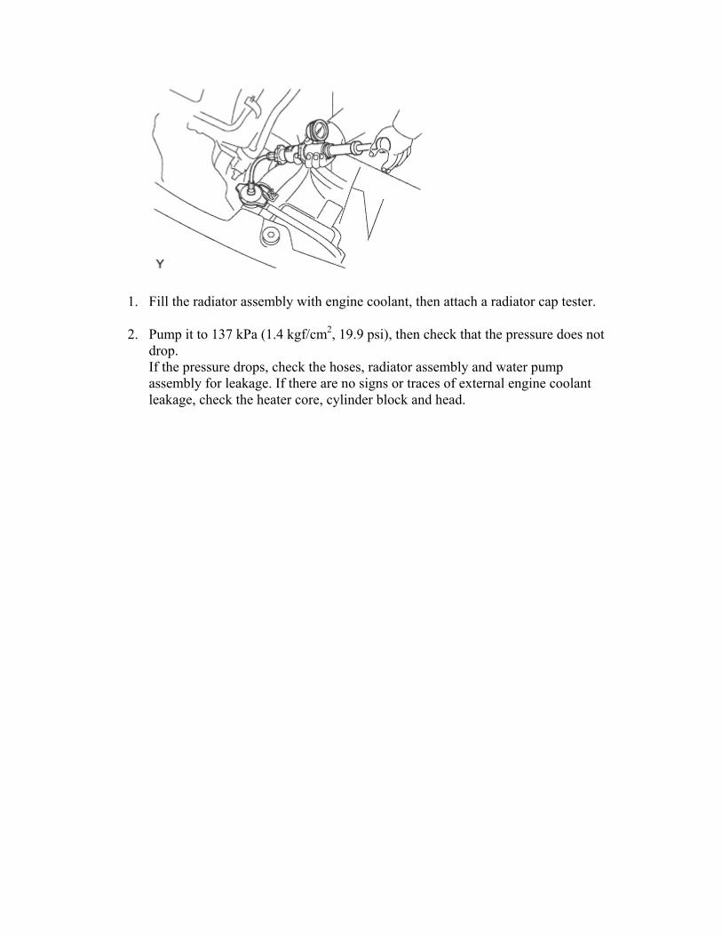
To avoid the danger of being burned, do not remove the radiator cap sub-assembly while the engine and radiator assembly are still hot. Thermal expansion will cause hot engine coolant and steam to blow out from the radiator assembly.
1. Fill the radiator assembly with engine coolant, then attach a radiator cap tester.
2. Pump it to 137 kPa (1.4 kgf/cm2, 19.9 psi), then check that the pressure does not drop. If the pressure drops, check the hoses, radiator assembly and water pump assembly for leakage. If there are no signs or traces of external engine coolant leakage, check the heater core, cylinder block and head.
2. INSPECT RESERVOIR TANK ENGINE COOLANT LEVEL
1. The engine coolant should be between the LOW and FULL lines when the engine is cold.
HINT: If it is below the LOW line, check for leakage and add Toyota Super Long Life Coolant or similar high quality ethylene glycol based non-silicate, non-amine, non-nitrite, and non-borate coolant with long-life hybrid organic acid technology up to the FULL line.
3. INSPECT ENGINE COOLANT QUALITY
1. Remove the radiator cap sub-assembly.
CAUTION: To avoid the danger of being burned, do not remove the radiator cap sub-assembly while the engine and radiator assembly are still hot. Thermal expansion will cause hot engine coolant and steam to blow out from the radiator assembly.
2. Check for excessive deposits of rust or scale around the radiator cap sub-assembly and radiator filler hole. The engine coolant should be free of oil. If excessively dirty, replace the engine coolant.
3. Reinstall the radiator cap sub-assembly.
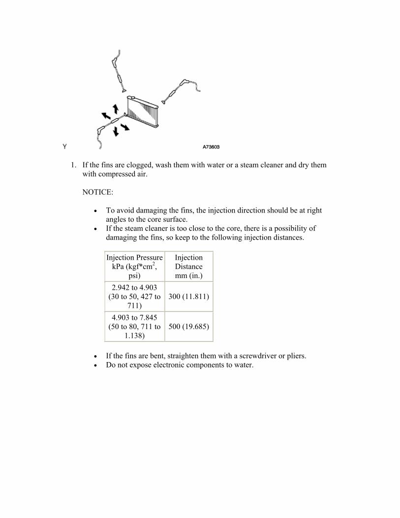
4. INSPECT FINS FOR BLOCKAGE
1. If the fins are clogged, wash them with water or a steam cleaner and dry them with compressed air.
NOTICE:
• To avoid damaging the fins, the injection direction should be at right angles to the core surface.
• If the steam cleaner is too close to the core, there is a possibility of damaging the fins, so keep to the following injection distances.
Injection PressurekPa (kgf*cm2,
psi)
Injection Distance mm (in.)
2.942 to 4.903 (30 to 50, 427 to
711) 300 (11.811)
4.903 to 7.845 (50 to 80, 711 to
1.138) 500 (19.685)
• If the fins are bent, straighten them with a screwdriver or pliers. • Do not expose electronic components to water.
COOLING FAN SYSTEM > PRECAUTION 1.IGNITION SWITCH EXPRESSIONS
1. The type of ignition switch used on this model differs according to the specifications of the vehicle. The expressions listed in the table below are used in this section.
Expression Ignition Switch (position) Engine Switch (condition)Ignition Switch off LOCK Off
Ignition Switch on (IG) ON On (IG) Ignition Switch on (ACC) ACC On (ACC)
Engine Start START Start
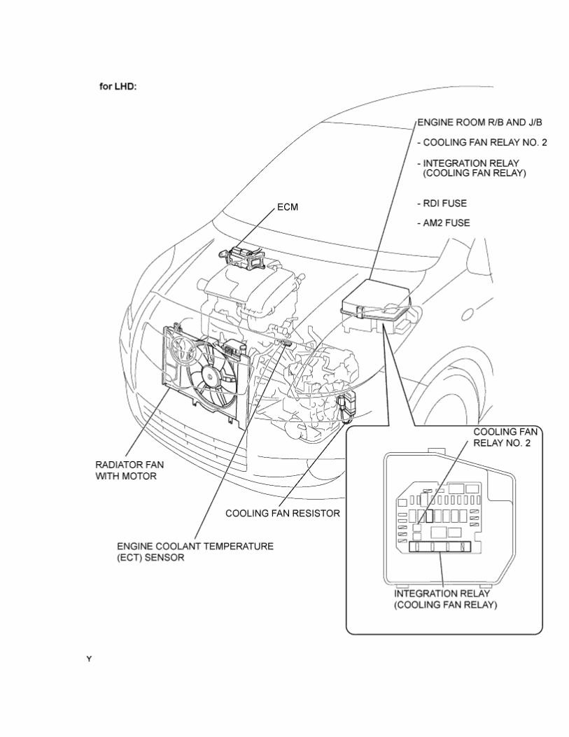
COOLING FAN SYSTEM > PARTS LOCATION
1 / 4
2 / 4
3 / 4
4 / 4
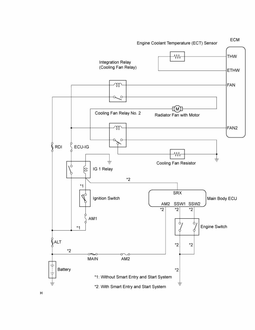
COOLING FAN SYSTEM > SYSTEM DIAGRAM
COOLING FAN SYSTEM > ON-VEHICLE INSPECTION CAUTION:
Be sure that the ignition is off if you work near the electric cooling fans or radiator grille. With the ignition on the electric cooling fans may automatically start to run if the engine coolant temperature is high and/or the air conditioning is on.
1. INSPECT COOLING FAN OPERATION AT LOW TEMPERATURES (Below 83°C (181°F))
1. Turn the ignition switch on (IG) and air conditioning switch off.
2. Check that the cooling fan stops. If not, check the cooling fan relay and engine coolant temperature sensor, and check if there is disconnection or an open circuit between them.
3. Disconnect the engine coolant temperature sensor connector.
4. Check that the cooling fan rotates. If not, check the fuses, cooling fan relay, ECM and cooling fan, and check for a short circuit between the cooing fan relay and engine coolant temperature sensor.
5. Reconnect the engine coolant temperature sensor connector.
2. INSPECT COOLING FAN OPERATION AT HIGH TEMPERATURES (Above 93°C (199°F))
1. Start the engine and air conditioning switch off, and raise the engine coolant temperature to above 93°C (199°F).
HINT: The engine coolant temperature is detected by the engine coolant temperature sensor on the water outlet.
2. Check that the cooling fan rotates. If not, replace the engine coolant temperature sensor.
3. INSPECT COOLING FAN MOTOR
1. Disconnect the cooling fan motor connector.
2. Connect the cooling fan connector to the battery and check that the fan motor moves smoothly.
3. Using an ammeter, measure the amperage between the terminals.
Standard current: w/ A/C 7.9 to 10.9 A (at 12 V) w/o A/C 5.2 to 8.2 A (at 12 V)
4. Connect the cooling fan motor connector.
COOLANT > REPLACEMENT CAUTION:
Be sure that the ignition is off if you work near the electric cooling fans or radiator grille. With the ignition on the electric cooling fans may automatically start to run if the engine coolant temperature is high and/or the air conditioning is on.
1. DRAIN ENGINE COOLANT CAUTION:
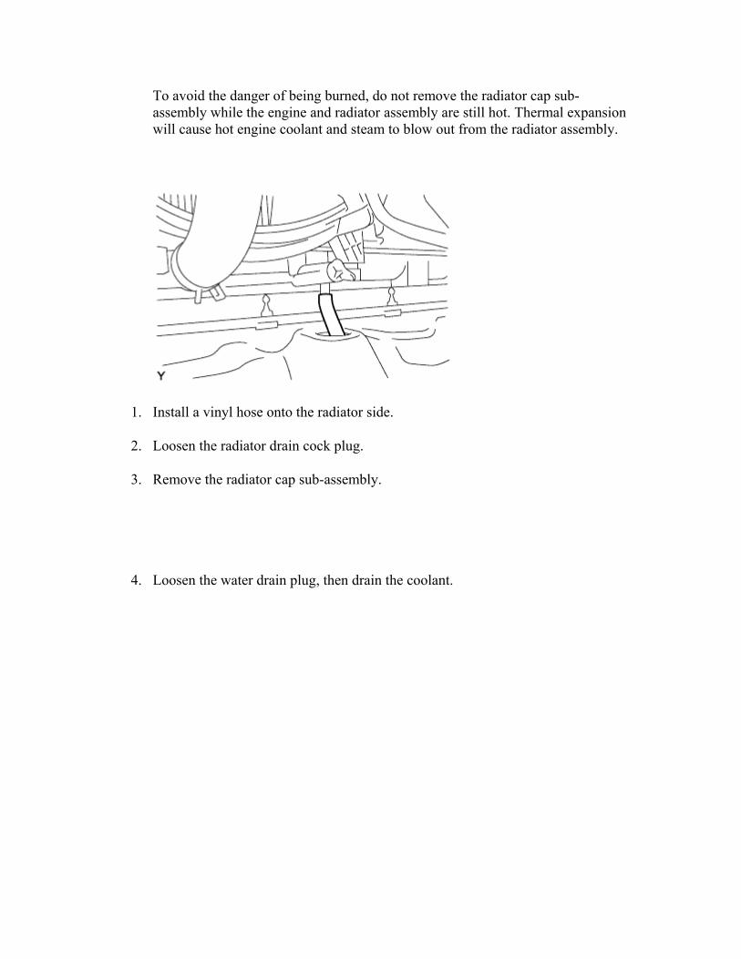
To avoid the danger of being burned, do not remove the radiator cap sub-assembly while the engine and radiator assembly are still hot. Thermal expansion will cause hot engine coolant and steam to blow out from the radiator assembly.
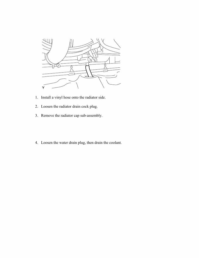
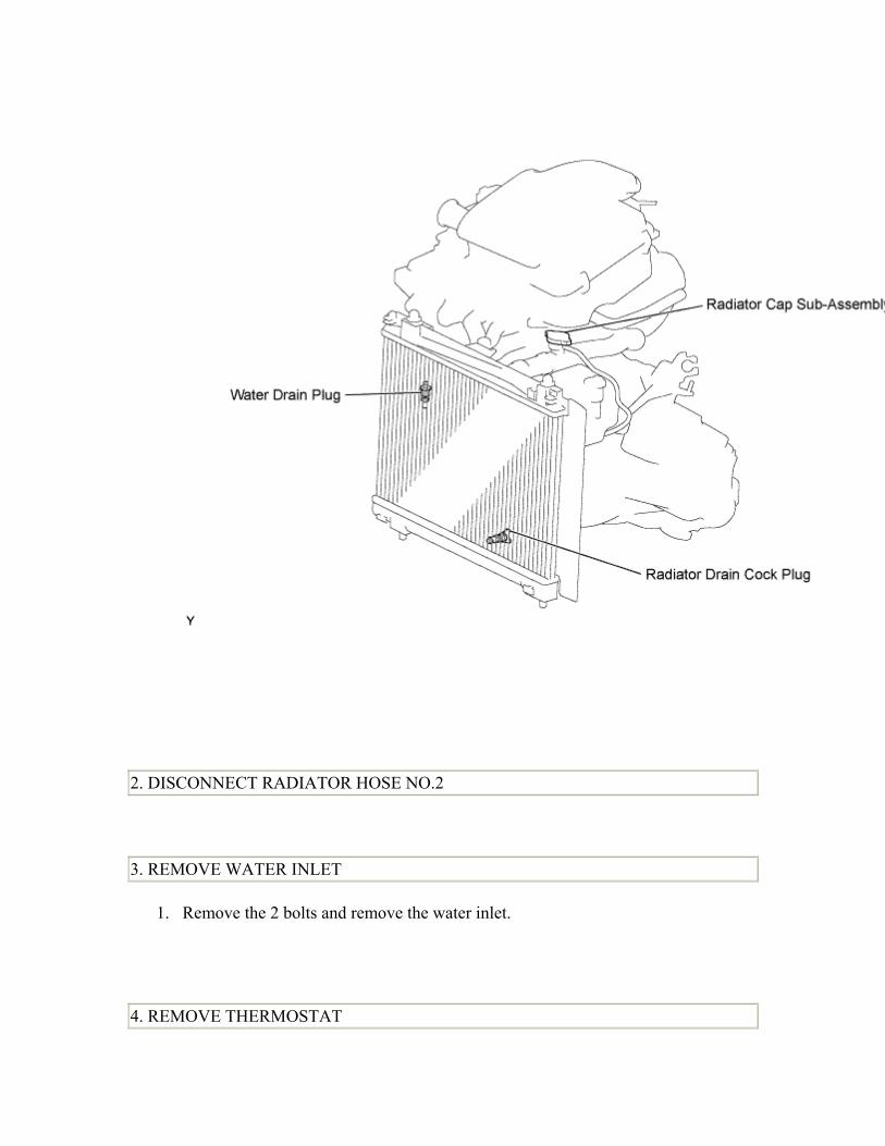
1. Install a vinyl hose onto the radiator side.
2. Loosen the radiator drain cock plug.
3. Remove the radiator cap sub-assembly.
4. Loosen the water drain plug, then drain the coolant.
2. ADD ENGINE COOLANT
1. Tighten all the plugs.
2. Disconnect the vinyl hose.
3. Pour engine coolant into the radiator assembly until it overflows.
Capacity: 4.5 liters (4.8 USqts, 4.2 lmp. qts) NOTICE: Do not substitute water for engine coolant. HINT:
• Use of improper engine coolant may damage the engine coolant system. • Use only Toyota Super Long Life Coolant or similar high quality ethylene
glycol based non-silicate, non-amine, non-nitrite, and non-borate engine coolant with long-life hybrid organic acid technology (coolant with long-life hybrid organic acid technology consists of a combination of low phosphates and organic acids).
4. Check the engine coolant level inside the radiator assembly by squeezing the inlet and outlet radiator hoses several times by hand. If the engine coolant level goes down, add engine coolant.
5. Install the radiator cap sub-assembly securely.
6. Slowly pour engine coolant into the radiator reservoir until it reaches the FULL line.
7. Warm up the engine until the cooling fan operates.
1. Set the air conditioning as follows while warming up the engine.
Item Manual air conditioning system
Automatic air conditioning system
Set control as follows
Fan speed - Any setting except "OFF" Temperature - Toward WARM Air conditioning switch "OFF"
Fan speed - Any setting except "OFF" Temperature - To the highest temperature Air conditioning switch "OFF""AUTO" switch "OFF"
2. Maintain the engine speed at 2,000 to 2,500 rpm and warm up the engine until the cooling fan operates.
8. Stop the engine and wait until the coolant cools down.
9. If the engine coolant level is below the full level, perform steps (c) through (h) again and repeat the operation until the engine coolant level stays at the full level.
10. Recheck the engine coolant level inside the radiator reservoir tank assembly. If it is below the full level, add engine coolant.
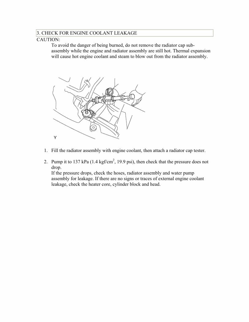
3. CHECK FOR ENGINE COOLANT LEAKAGE CAUTION:
To avoid the danger of being burned, do not remove the radiator cap sub-assembly while the engine and radiator assembly are still hot. Thermal expansion will cause hot engine coolant and steam to blow out from the radiator assembly.
1. Fill the radiator assembly with engine coolant, then attach a radiator cap tester.
2. Pump it to 137 kPa (1.4 kgf/cm2, 19.9 psi), then check that the pressure does not drop. If the pressure drops, check the hoses, radiator assembly and water pump assembly for leakage. If there are no signs or traces of external engine coolant leakage, check the heater core, cylinder block and head.
To avoid the danger of being burned, do not remove the radiator cap sub-assembly while the engine and radiator assembly are still hot. Thermal expansion will cause hot engine coolant and steam to blow out from the radiator assembly.
1. Install a vinyl hose onto the radiator side.
2. Loosen the radiator drain cock plug.
3. Remove the radiator cap sub-assembly.
4. Loosen the water drain plug, then drain the coolant.
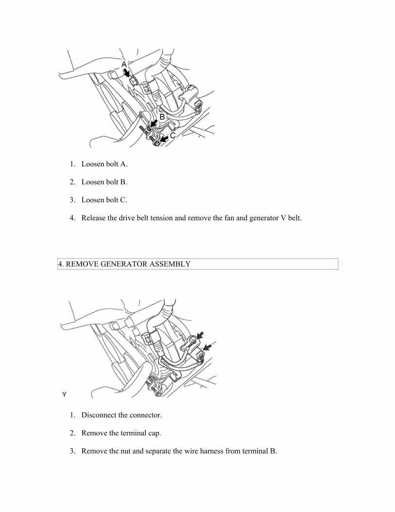
3. REMOVE FAN AND GENERATOR V BELT
1. Loosen bolt A.
2. Loosen bolt B.
3. Loosen bolt C.
4. Release the drive belt tension and remove the fan and generator V belt.
4. REMOVE GENERATOR ASSEMBLY
1. Disconnect the connector.
2. Remove the terminal cap.
3. Remove the nut and separate the wire harness from terminal B.
4. Disengage the 2 clamps and separate the wire harness.
5. Remove the 2 bolts and remove the generator assembly.
5. REMOVE FAN BELT ADJUSTING BAR
1. Remove the bolt and remove the fan belt adjusting bar.
6. REMOVE WATER PUMP ASSEMBLY
1. Remove the 5 bolts and remove the water pump.
2. Remove the gasket.
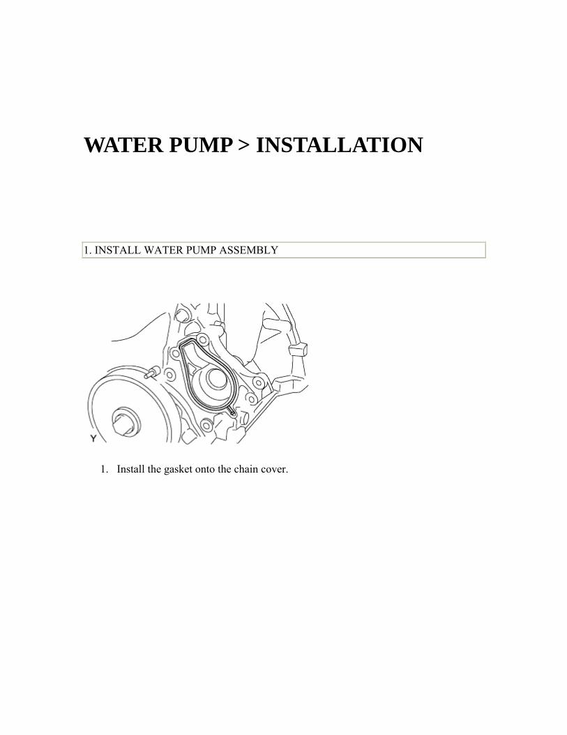
WATER PUMP > INSTALLATION 1. INSTALL WATER PUMP ASSEMBLY
1. Install the gasket onto the chain cover.
2. Provisionally tighten the water pump with the 5 bolts.
3. Tighten the water pump with the 5 bolts.
Torque: 28 N*m 286 kgf*cm , 21 ft.*lbf NOTICE: Tighten the bolts and nuts in the sequence shown in the illustration.
2. INSTALL FAN BELT ADJUSTING BAR
1. Install the fan belt adjusting bar with the bolt.
Torque: 34 N*m 347 kgf*cm , 25 ft.*lbf
3. INSTALL GENERATOR ASSEMBLY
1. Provisionally tighten the generator with the 2 bolts.
2. Install the wire harness onto terminal B with the nut.
Torque: 9.8 N*m 100 kgf*cm , 7.2 in.*lbf
3. Install the terminal cap.
4. Connect the connector.
5. Engage the 2 clamps and install the wire harness.
4. CONNECT CABLE TO NEGATIVE BATTERY TERMINAL Torque:
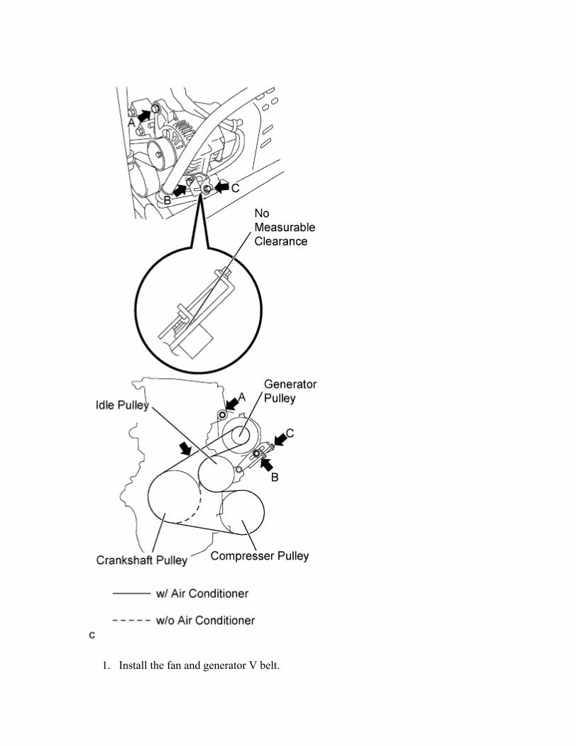
5.4 N*m 55 kgf*cm , 48 in.*lbf 5. INSTALL FAN AND GENERATOR V BELT
1. Install the fan and generator V belt.
2. Gently tighten bolt B until there is no measurable clearance.
3. Turn bolt C to adjust the tension of the fan and generator V belt.
4. Inspect the fan and generator V belt.
5. Tighten bolt B.
Torque: 34 N*m 347 kgf*cm , 25 ft.*lbf
6. Tighten bolt A.
Torque: 54 N*m 551 kgf*cm , 40 ft.*lbf
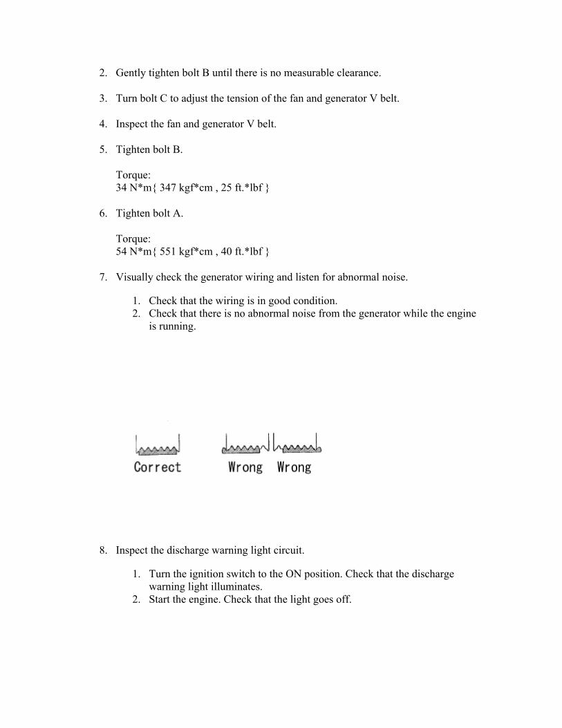
7. Visually check the generator wiring and listen for abnormal noise.
1. Check that the wiring is in good condition. 2. Check that there is no abnormal noise from the generator while the engine
is running.
8. Inspect the discharge warning light circuit.
1. Turn the ignition switch to the ON position. Check that the discharge warning light illuminates.
2. Start the engine. Check that the light goes off.
6. INSPECT DRIVE BELT DEFLECTION AND TENSION
1. Check the belt deflection by pressing on the belt at the points indicated by the arrow marks in the illustration.
Deflection: Item Specified Condition
New belt 7 to 8 mm (0.28 to 0.31 in.)Used belt
9 to 11 mm (0.35 to 0.43 in.)
If the belt deflection is not as specified, adjust it.
HINT:
• The most appropriate force for the adjustment above is 98 N (10 kgf, 22 lbf).
• New belt refers to a belt which has been used on a running engine for less than 5 minutes.
• Used belt refers to a belt which has been used on a running engine for 5 minutes or more.
• After installing a belt, check that it fits properly in the ribbed grooves. • Check with your hand to confirm that the belt has not slipped out of the
groove on the bottom of the pulley. • After installing a new belt, run the engine for about 5 minutes and recheck
the belt tension.
2. Adjust fan and generator V belt tension.
1. Loosen bolt A. 2. Loosen bolt B. 3. Gently tighten bolt B until there is no measurable clearance. 4. Turn bolt C to adjust the tension of the fan and generator V belt. 5. Tighten bolt B.
Torque: 34 N*m 347 kgf*cm , 25 ft.*lbf
6. Tighten bolt A.
Torque: 54 N*m 551 kgf*cm , 40 ft.*lbf
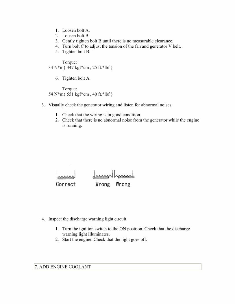
3. Visually check the generator wiring and listen for abnormal noises.
1. Check that the wiring is in good condition. 2. Check that there is no abnormal noise from the generator while the engine
is running.
4. Inspect the discharge warning light circuit.
1. Turn the ignition switch to the ON position. Check that the discharge warning light illuminates.
2. Start the engine. Check that the light goes off.
7. ADD ENGINE COOLANT
1. Tighten all the plugs.
2. Disconnect the vinyl hose.
3. Pour engine coolant into the radiator assembly until it overflows.
Capacity: 4.5 liters (4.8 USqts, 4.2 lmp. qts) NOTICE: Do not substitute water for engine coolant. HINT:
• Use of improper engine coolant may damage the engine coolant system. • Use only Toyota Super Long Life Coolant or similar high quality ethylene
glycol based non-silicate, non-amine, non-nitrite, and non-borate engine coolant with long-life hybrid organic acid technology (coolant with long-life hybrid organic acid technology consists of a combination of low phosphates and organic acids).
4. Check the engine coolant level inside the radiator assembly by squeezing the inlet and outlet radiator hoses several times by hand. If the engine coolant level goes down, add engine coolant.
5. Install the radiator cap sub-assembly securely.
6. Slowly pour engine coolant into the radiator reservoir until it reaches the FULL line.
7. Warm up the engine until the cooling fan operates.
1. Set the air conditioning as follows while warming up the engine.
Item Manual air conditioning system
Automatic air conditioning system
Set control as follows
Fan speed - Any setting except "OFF" Temperature - Toward WARM Air conditioning switch "OFF"
Fan speed - Any setting except "OFF" Temperature - To the highest temperature Air conditioning switch "OFF""AUTO" switch "OFF"
2. Maintain the engine speed at 2,000 to 2,500 rpm and warm up the engine until the cooling fan operates.
8. Stop the engine and wait until the coolant cools down.
9. If the engine coolant level is below the full level, perform steps (c) through (h) again and repeat the operation until the engine coolant level stays at the full level.
10. Recheck the engine coolant level inside the radiator reservoir tank assembly. If it is below the full level, add engine coolant.
8. CHECK FOR ENGINE COOLANT LEAKAGE CAUTION:
To avoid the danger of being burned, do not remove the radiator cap sub-assembly while the engine and radiator assembly are still hot. Thermal expansion will cause hot engine coolant and steam to blow out from the radiator assembly.
1. Fill the radiator assembly with engine coolant, then attach a radiator cap tester.
2. Pump it to 137 kPa (1.4 kgf/cm2, 19.9 psi), then check that the pressure does not drop. If the pressure drops, check the hoses, radiator assembly and water pump assembly for leakage. If there are no signs or traces of external engine coolant leakage, check the heater core, cylinder block and head.
To avoid the danger of being burned, do not remove the radiator cap sub-assembly while the engine and radiator assembly are still hot. Thermal expansion will cause hot engine coolant and steam to blow out from the radiator assembly.
1. Install a vinyl hose onto the radiator side.
2. Loosen the radiator drain cock plug.
3. Remove the radiator cap sub-assembly.
4. Loosen the water drain plug, then drain the coolant.
2. DISCONNECT RADIATOR HOSE NO.2 3. REMOVE WATER INLET
1. Remove the 2 bolts and remove the water inlet.
4. REMOVE THERMOSTAT
THERMOSTAT > INSPECTION 1. INSPECT THERMOSTAT
HINT: The valve opening temperature is inscribed on the thermostat.
1. Immerse the thermostat in water, then gradually heat the water.
2. Check the valve opening temperature of the thermostat.
Valve opening temperature: 80 to 84°C (176 to 183°F)
If the valve opening temperature is not as specified, replace the thermostat.
3. Inspect the valve lift.
Valve lift: Temperature Valve lift
95°C (205°F)
8.5 mm (0.335 in.) or more
If the valve lift is not as specified, replace the thermostat.
4. Check that the valve is fully closed when the thermostat is at low temperatures (below 75°C (167°F)). If the valve lift is not as specified, replace the thermostat.
THERMOSTAT > INSTALLATION 1. INSTALL THERMOSTAT
1. Install a new gasket onto the thermostat.
2. Install the thermostat into the water inlet with the jiggle pin facing straight upward.
2. INSTALL WATER INLET
1. Install the water inlet with the 2 bolts.
Torque: 7.0 N*m 71 kgf*cm , 62 in.*lbf NOTICE:
• Avoid catching the rubber gasket of thermostat under the water inlet. • Do not use a water inlet that has been dropped. • Ensure that the gasket is secured between the water inlet and block.
3. Pour engine coolant into the radiator assembly until it overflows.
Capacity: 4.5 liters (4.8 USqts, 4.2 lmp. qts) NOTICE: Do not substitute water for engine coolant. HINT:
• Use of improper engine coolant may damage the engine coolant system. • Use only Toyota Super Long Life Coolant or similar high quality ethylene
glycol based non-silicate, non-amine, non-nitrite, and non-borate engine coolant with long-life hybrid organic acid technology (coolant with long-life hybrid organic acid technology consists of a combination of low phosphates and organic acids).
4. Check the engine coolant level inside the radiator assembly by squeezing the inlet and outlet radiator hoses several times by hand. If the engine coolant level goes down, add engine coolant.
5. Install the radiator cap sub-assembly securely.
6. Slowly pour engine coolant into the radiator reservoir until it reaches the FULL line.
7. Warm up the engine until the cooling fan operates.
1. Set the air conditioning as follows while warming up the engine.
Item Manual air conditioning system
Automatic air conditioning system
Set control as follows
Fan speed - Any setting except "OFF" Temperature - Toward WARM Air conditioning switch "OFF"
Fan speed - Any setting except "OFF" Temperature - To the highest temperature Air conditioning switch "OFF""AUTO" switch "OFF"
2. Maintain the engine speed at 2,000 to 2,500 rpm and warm up the engine until the cooling fan operates.
8. Stop the engine and wait until the coolant cools down.
9. If the engine coolant level is below the full level, perform steps (c) through (h) again and repeat the operation until the engine coolant level stays at the full level.
10. Recheck the engine coolant level inside the radiator reservoir tank assembly. If it is below the full level, add engine coolant.
5. CHECK FOR ENGINE COOLANT LEAKAGE CAUTION:
To avoid the danger of being burned, do not remove the radiator cap sub-assembly while the engine and radiator assembly are still hot. Thermal expansion will cause hot engine coolant and steam to blow out from the radiator assembly.
1. Fill the radiator assembly with engine coolant, then attach a radiator cap tester.
2. Pump it to 137 kPa (1.4 kgf/cm2, 19.9 psi), then check that the pressure does not drop. If the pressure drops, check the hoses, radiator assembly and water pump assembly for leakage. If there are no signs or traces of external engine coolant leakage, check the heater core, cylinder block and head.
COOLING FAN RELAY > ON-VEHICLE INSPECTION 1. INSPECT COOLING FAN RELAY NO. 2
1. Check the resistance.
1. Using an ohmmeter, measure the resistance between the terminals.
Standard resistance: Tester
Connection Specified Condition
3 - 4 Below 1 Ω
3 - 4
10 kΩ or higher (when battery
voltage applied to terminals 1 and 2)
3 - 5 10 kΩ or higher
3 - 5
Below 1 Ω (when battery voltage
applied to terminals 1 and 2)
If the result is not as specified, replace the relay.
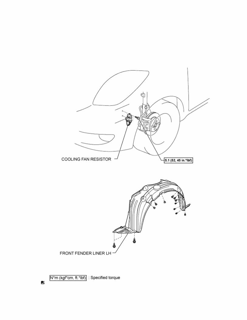
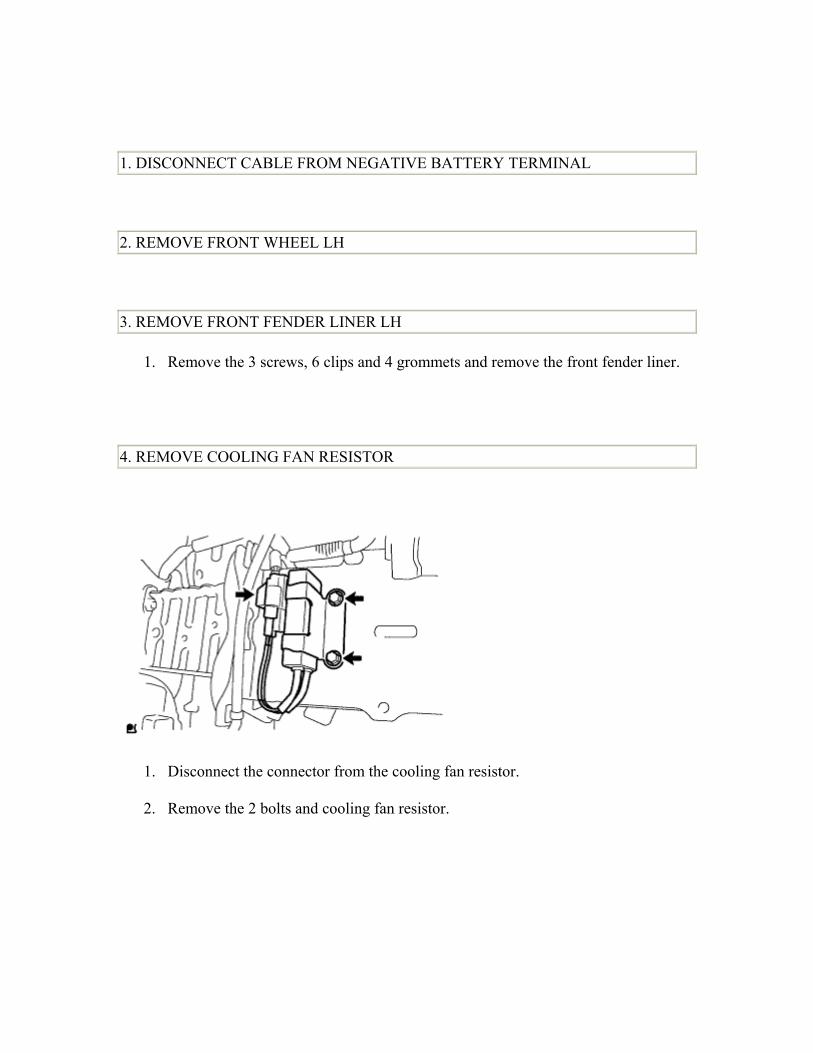
1. DISCONNECT CABLE FROM NEGATIVE BATTERY TERMINAL 2. REMOVE FRONT WHEEL LH 3. REMOVE FRONT FENDER LINER LH
1. Remove the 3 screws, 6 clips and 4 grommets and remove the front fender liner.
4. REMOVE COOLING FAN RESISTOR
1. Disconnect the connector from the cooling fan resistor.
2. Remove the 2 bolts and cooling fan resistor.
COOLING FAN RESISTOR > INSPECTION 1. INSPECT COOLING FAN RESISTOR
1. Using an ohmmeter, measure the resistance between the terminals.
Standard resistance: 1.17 to 1.43 Ω at 20°C (68°F)
COOLING FAN RESISTOR > INSTALLATION 1. INSTALL COOLING FAN RESISTOR
1. Install the cooling fan resistor with the 2 bolts.
Torque: 5.1 N*m 52 kgf*cm , 45 in.*lbf
2. Connect the cooling fan resistor connector.
2. INSTALL FRONT FENDER LINER LH
1. Install the front fender liner with the 3 screws, 6 clips and 4 grommets.
NOTICE: The speed sensor wire should not protrude beyond the front fender liner.
3. INSTALL FRONT WHEEL LH 4. CONNECT CABLE TO NEGATIVE BATTERY TERMINAL Torque:
5.4 N*m 55 kgf*cm , 48 in.*lbf
RADIATOR > COMPONENTS
1 / 4
2 / 4
3 / 4
4 / 4
RADIATOR > ON-VEHICLE INSPECTION
1. CHECK RADIATOR CAP SUB-ASSEMBLY
1. Measure the valve opening pressure.
1. If there are water stains or foreign matter on rubber packings 1, 2 or 3, clean the part(s) with water and finger scouring.
2. Check that rubber packings 1, 2 and 3 are not deformed, cracked or swollen.
3. Check that rubber packings 3 and 4 are not stuck together. 4. Apply engine coolant to rubber packings 2 and 3 before using the radiator
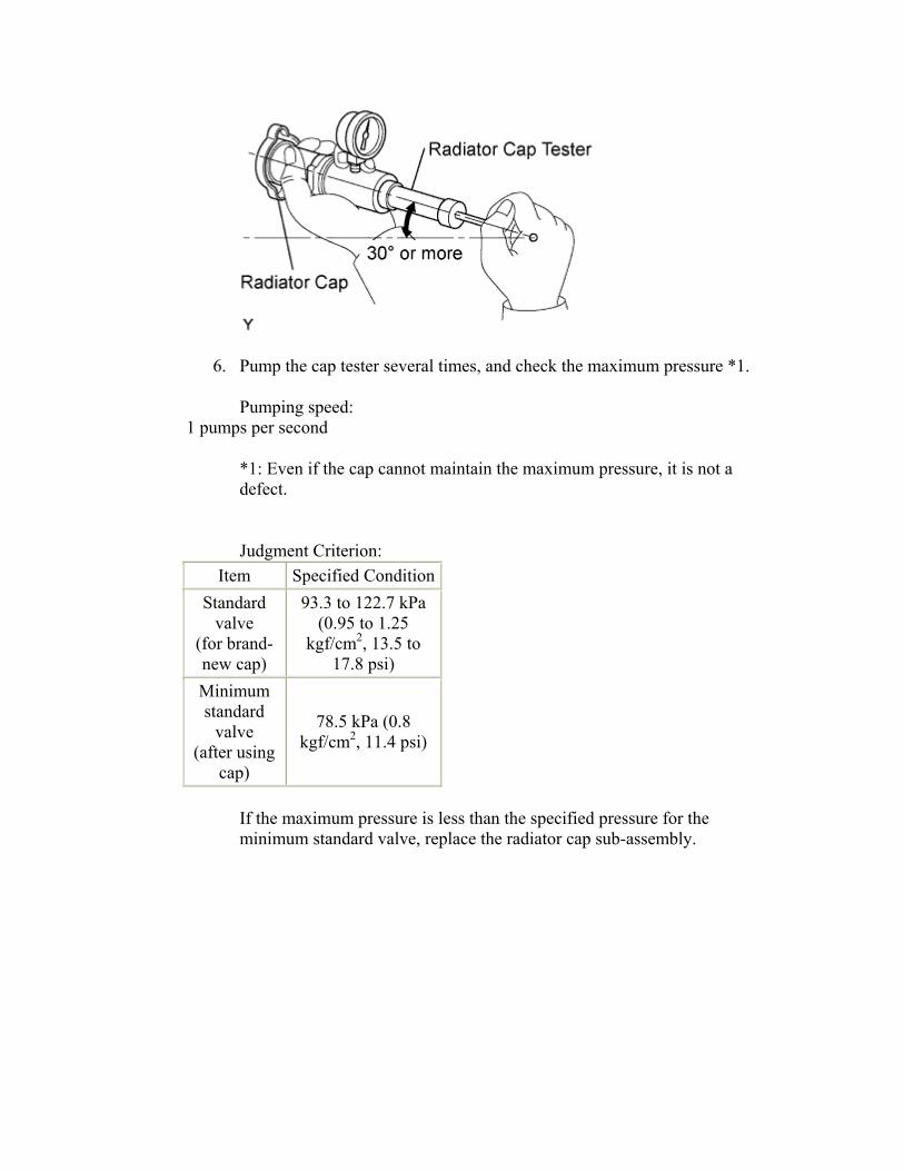
cap tester. 5. When using the cap tester, tilt it to more than 30 degrees.
6. Pump the cap tester several times, and check the maximum pressure *1.
Pumping speed: 1 pumps per second
*1: Even if the cap cannot maintain the maximum pressure, it is not a defect.
Judgment Criterion: Item Specified Condition
Standard valve
(for brand-new cap)
93.3 to 122.7 kPa (0.95 to 1.25
kgf/cm2, 13.5 to 17.8 psi)
Minimum standard
valve (after using
cap)
78.5 kPa (0.8 kgf/cm2, 11.4 psi)
If the maximum pressure is less than the specified pressure for the minimum standard valve, replace the radiator cap sub-assembly.
RADIATOR > REMOVAL CAUTION:
Be sure that the ignition is off if you work near the electric cooling fans or radiator grille. With the ignition on the electric cooling fans may automatically start to run if the engine coolant temperature is high and/or the air conditioning is on.
To avoid the danger of being burned, do not remove the radiator cap sub-assembly while the engine and radiator assembly are still hot. Thermal expansion will cause hot engine coolant and steam to blow out from the radiator assembly.
1. Install a vinyl hose onto the radiator side.
2. Loosen the radiator drain cock plug.
3. Remove the radiator cap sub-assembly.
4. Loosen the water drain plug, then drain the coolant.
3. REMOVE FRONT SPOILER COVER LH (w/ Front Spoiler)
1. Remove the 5 screws and the front spoiler cover.
4. REMOVE FRONT SPOILER COVER (w/ Front Spoiler)
1. Remove the 4 screws and the front spoiler cover.
5. REMOVE FRONT BUMPER COVER
1. Apply protective tape as shown in the illustration.
2. w/ Front Spoiler:
1. Remove the 3 screws.
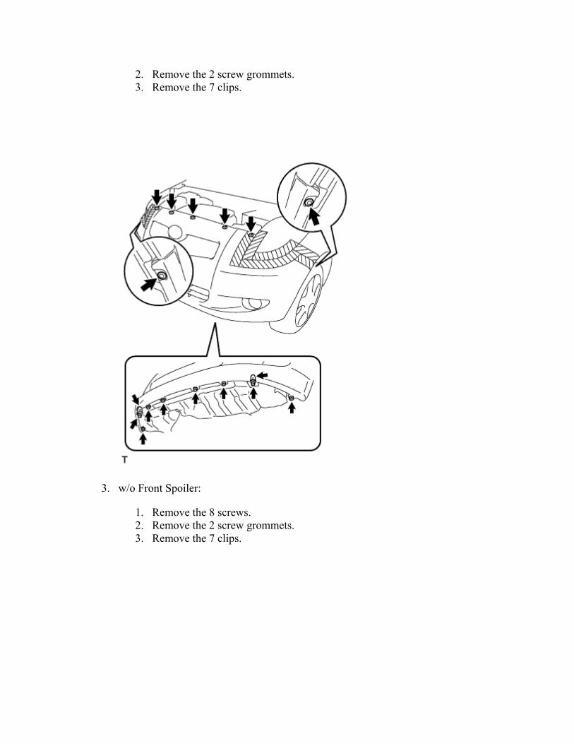
2. Remove the 2 screw grommets. 3. Remove the 7 clips.
3. w/o Front Spoiler:
1. Remove the 8 screws. 2. Remove the 2 screw grommets. 3. Remove the 7 clips.
4. w/ Fog Light:
1. Using a screwdriver with its tip wrapped in protective tape, disengage the 6 claws and remove the front bumper cover.
2. Disconnect the 2 fog light connectors.
5. w/o Fog Light:
1. Using a screwdriver with its tip wrapped in protective tape, disengage the 6 claws and remove the front bumper cover.
6. w/ Front Spoiler:
1. Remove the 2 clips and the 4 screw grommets.
7. w/o Front Spoiler:
1. Remove the 2 clips and the screw grommet.
6. REMOVE RADIATOR SUPPORT ABSORBER UPPER
1. Using a screwdriver, disengage the 6 claws and remove the radiator support upper absorber.
7. REMOVE RADIATOR SIDE AIR SEAL NO. 2
1. Disengage the 2 claws and remove radiator side air seal No. 2.
8. REMOVE RADIATOR SIDE AIR SEAL NO. 1
1. Disengage the 2 claws and remove radiator side air seal No. 1.
9. REMOVE COOLER COVER NO.1 (w/ Air Conditioning System)
1. Remove the 2 clips and cooler cover No. 1.
10. DISCONNECT RADIATOR HOSE NO.1
1. Loosen the clip and disconnect radiator hose No. 1.
11. DISCONNECT RADIATOR HOSE NO.2
1. Loosen the clip and disconnect radiator hose No. 2.
12. REMOVE HOOD LOCK ASSEMBLY
1. Separate the hood lock control cable assembly from the 2 clamps.
2. Remove the 3 bolts and remove the hood lock assembly.
13. REMOVE RADIATOR SUPPORT SUB-ASSEMBLY UPPER
1. Separate the horn connector.
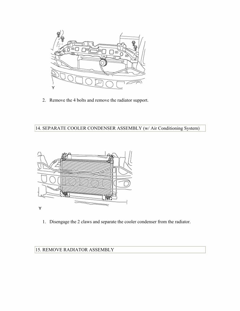
2. Remove the 4 bolts and remove the radiator support.
14. SEPARATE COOLER CONDENSER ASSEMBLY (w/ Air Conditioning System)
1. Disengage the 2 claws and separate the cooler condenser from the radiator.
15. REMOVE RADIATOR ASSEMBLY
1. Separate the clamp and separate the fan motor connector.
2. Disengage the 3 clamps for the oxygen sensor wire harness.
3. Remove the radiator assembly from the vehicle.
16. REMOVE WATER FILLER BRACKET
1. Remove the 2 bolts and separate the water filler bracket.
2. Separate the radiator reserve tank hose.
3. Separate radiator hose No. 3.
17. REMOVE FAN SHROUD 18. REMOVE RADIATOR SUPPORT CUSHION 19. REMOVE RADIATOR RESERVE TANK HOSE GROMMET
RADIATOR > INSTALLATION 1. INSTALL RADIATOR RESERVE TANK HOSE GROMMET 2. INSTALL RADIATOR SUPPORT CUSHION 3. INSTALL FAN SHROUD 4. INSTALL WATER FILLER BRACKET
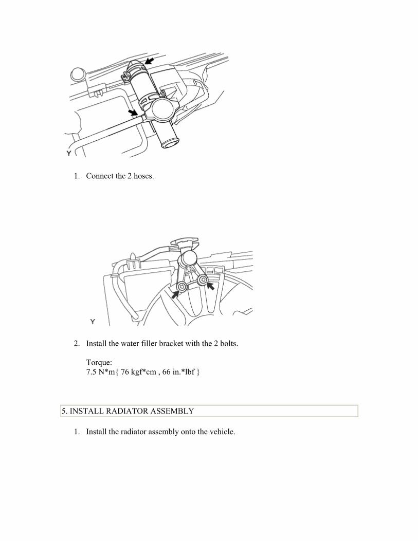
1. Connect the 2 hoses.
2. Install the water filler bracket with the 2 bolts.
Torque: 7.5 N*m 76 kgf*cm , 66 in.*lbf
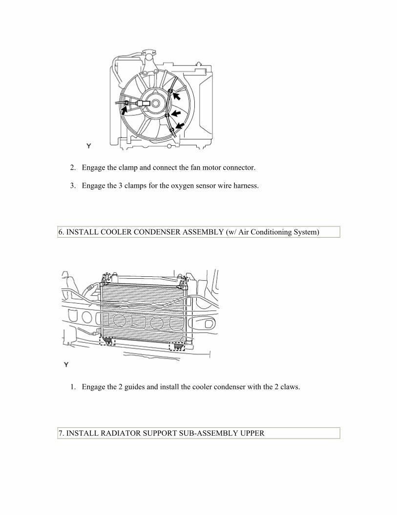
5. INSTALL RADIATOR ASSEMBLY
1. Install the radiator assembly onto the vehicle.
2. Engage the clamp and connect the fan motor connector.
3. Engage the 3 clamps for the oxygen sensor wire harness.
6. INSTALL COOLER CONDENSER ASSEMBLY (w/ Air Conditioning System)
1. Engage the 2 guides and install the cooler condenser with the 2 claws.
7. INSTALL RADIATOR SUPPORT SUB-ASSEMBLY UPPER
1. Install the radiator support with the 4 bolts.
Torque: 5.5 N*m 56 kgf*cm , 49 in.*lbf
2. Connect the horn connector.
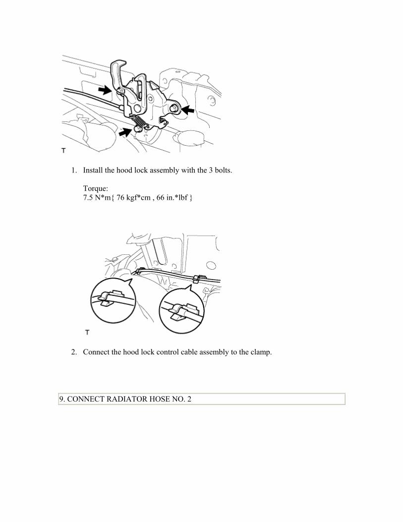
8. INSTALL HOOD LOCK ASSEMBLY
1. Install the hood lock assembly with the 3 bolts.
Torque: 7.5 N*m 76 kgf*cm , 66 in.*lbf
2. Connect the hood lock control cable assembly to the clamp.
9. CONNECT RADIATOR HOSE NO. 2
1. Connect radiator hose No. 2 with the clip.
10. CONNECT RADIATOR HOSE NO. 1
1. Connect radiator hose No. 1 with the clip.
11. INSTALL COOLER COVER NO. 1 (w/ Air Conditioning System)
1. Install cooler cover No. 1 with the 2 clips.
12. INSTALL RADIATOR SIDE AIR SEAL NO. 1
1. Engage the 2 claws and install radiator side air seal No. 1.
13. INSTALL RADIATOR SIDE AIR SEAL NO. 2
1. Engage the 2 claws and install radiator side air seal No. 2.
14. INSTALL RADIATOR SUPPORT ABSORBER UPPER
1. Engage the 6 claws and install the radiator support upper absorber.
15. INSTALL FRONT BUMPER COVER
1. w/ Front Spoiler:
1. Install the 2 clips and the 4 screw grommets.
2. w/o Front Spoiler:
1. Install the 2 clips and the screw grommet.
3. w/ Fog Light:
1. Connect the 2 fog light connectors. 2. Engage the 6 claws and install the front bumper cover.
4. w/o Fog Light:
1. Engage the 6 claws and install the front bumper cover.
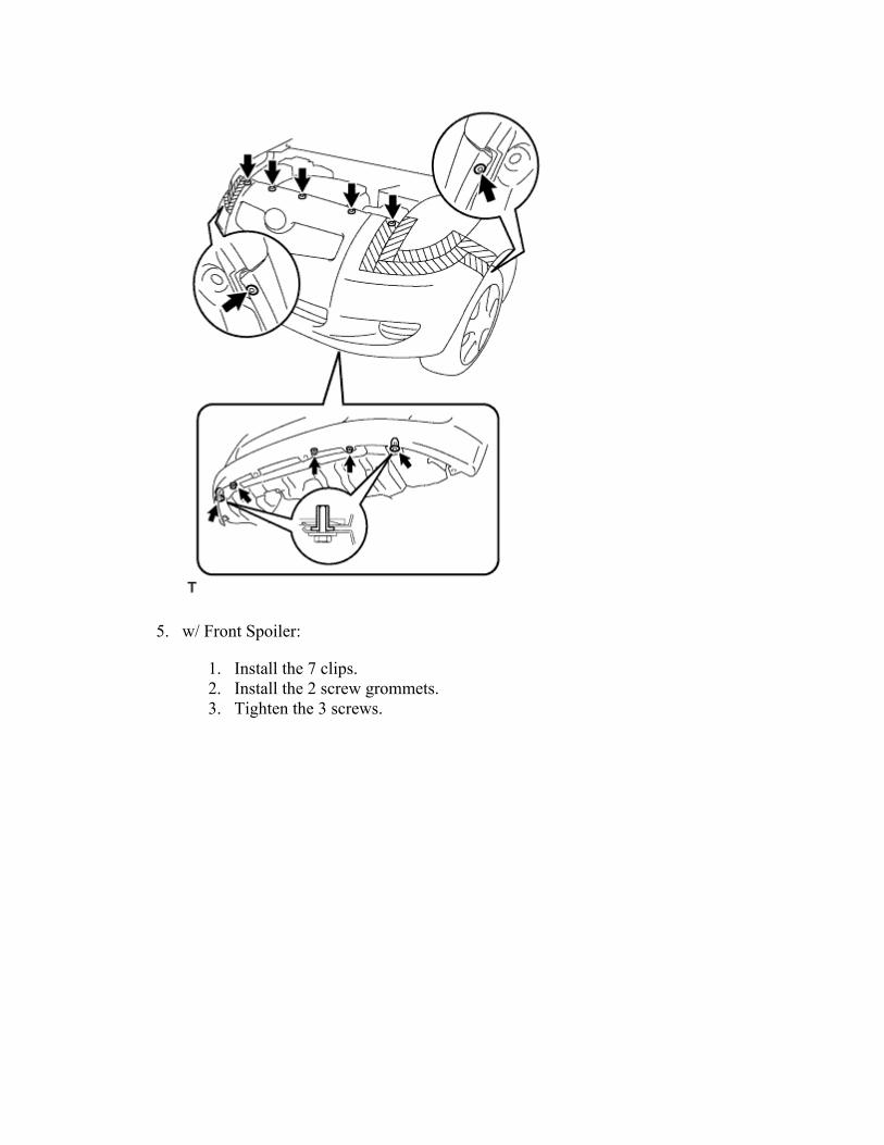
5. w/ Front Spoiler:
1. Install the 7 clips. 2. Install the 2 screw grommets. 3. Tighten the 3 screws.
6. w/o Front Spoiler:
1. Install the 7 clips. 2. Install the 2 screw grommets. 3. Tighten the 8 screws.
7. Remove the protective tape.
16. INSTALL FRONT SPOILER COVER (w/ Front Spoiler)
1. Install the front spoiler cover with the 4 screws.
17. INSTALL FRONT SPOILER COVER LH (w/ Front Spoiler)
1. Install the front spoiler cover with the 5 screws.
18. CONNECT CABLE TO NEGATIVE BATTERY TERMINAL Torque:
3. Pour engine coolant into the radiator assembly until it overflows.
Capacity: 4.5 liters (4.8 USqts, 4.2 lmp. qts) NOTICE: Do not substitute water for engine coolant. HINT:
• Use of improper engine coolant may damage the engine coolant system.
• Use only Toyota Super Long Life Coolant or similar high quality ethylene glycol based non-silicate, non-amine, non-nitrite, and non-borate engine coolant with long-life hybrid organic acid technology (coolant with long-life hybrid organic acid technology consists of a combination of low phosphates and organic acids).
4. Check the engine coolant level inside the radiator assembly by squeezing the inlet and outlet radiator hoses several times by hand. If the engine coolant level goes down, add engine coolant.
5. Install the radiator cap sub-assembly securely.
6. Slowly pour engine coolant into the radiator reservoir until it reaches the FULL line.
7. Warm up the engine until the cooling fan operates.
1. Set the air conditioning as follows while warming up the engine.
Item Manual air conditioning system
Automatic air conditioning system
Set control as follows
Fan speed - Any setting except "OFF" Temperature - Toward WARM Air conditioning switch "OFF"
Fan speed - Any setting except "OFF" Temperature - To the highest temperature Air conditioning switch "OFF""AUTO" switch "OFF"
2. Maintain the engine speed at 2,000 to 2,500 rpm and warm up the engine until the cooling fan operates.
8. Stop the engine and wait until the coolant cools down.
9. If the engine coolant level is below the full level, perform steps (c) through (h) again and repeat the operation until the engine coolant level stays at the full level.
10. Recheck the engine coolant level inside the radiator reservoir tank assembly. If it is below the full level, add engine coolant.
20. ADJUST HOOD LOCK ASSEMBLY
1. Loosen the 3 bolts.
2. Adjust the hood lock position so that the striker can enter it smoothly.
3. Tighten the 3 bolts after the adjustment.
Torque: 7.5 N*m 76 kgf*cm , 66 in.*lbf
21. CHECK FOR ENGINE COOLANT LEAKAGE CAUTION:
To avoid the danger of being burned, do not remove the radiator cap sub-assembly while the engine and radiator assembly are still hot. Thermal expansion will cause hot engine coolant and steam to blow out from the radiator assembly.
1. Fill the radiator assembly with engine coolant, then attach a radiator cap tester.
2. Pump it to 137 kPa (1.4 kgf/cm2, 19.9 psi), then check that the pressure does not drop. If the pressure drops, check the hoses, radiator assembly and water pump assembly for leakage. If there are no signs or traces of external engine coolant leakage, check the heater core, cylinder block and head.