www.unitedcoolair.com @ Installa Installa Installa Installa Installation Man tion Man tion Man tion Man tion Manual ual ual ual u a l COOLSPO COOLSPO COOLSPO COOLSPO COOLSPO T SERIES T SERIES T SERIES T SERIES T SERIES AIR CONDITIONING UNITS AIR CONDITIONING UNITS AIR CONDITIONING UNITS AIR CONDITIONING UNITS AIR CONDITIONING UNITS 1 Ton – 3 Ton Air-Cooled • Water-Cooled • Chilled Waterfo r0008VI
Inspection of Equipment .................................................. 6Handling ........................................................................... 6Location ........................................................................... 6Minimum Service Access ................................................ 6Application Data .............................................................. 6Mounting .......................................................................... 7
Figure 2: Orientation of Grilles .................................. 5Figure 3A: Top View of Unit Showing Mounts ........ 5Figure 3B: Sectional View of Vibration Isolators...... 5
Blower Motor Lubrication ............................................. 20Belts ........................................................................... 21Refrigerant Systems ....................................................... 21Evaporator and Air-cooled Condenser Coils ................. 21
SECTION 3 – SEQUENCE OF OPERATIONCooling Sequence of Operation ..................................... 22Heating Sequence of Operation
(other than heat pump) ............................................. 22Heat Pump Heating Sequence of Operation .................. 23
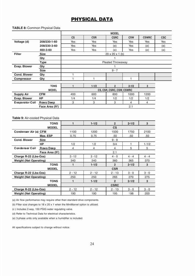
SECTION 4 – PHYSICAL DATATable 8: Common Physical Data .............................. 24Table 9: Air-cooled Physical Data ........................... 24Table 10: Water-cooled Physical Data ..................... 25Table 11: Chilled Water Physical Data .................... 25
Immediately upon receiving the unit it should beinspected for possible external damage incurred
during transit. If damage is evident it should benoted on the carrier’s freight bill. A separate re-quest for inspection by the carrier’s agent should
be made in writing. Protective packaging and skidsshould not be removed until the unit is at the pointof installation. When removing packaging, be care-ful not to scratch and dent the unit.
After removal of packaging, all access panels should be removed to inspect the interior compartmentsfor damage.
NOTE: Items that are shipped loose are typi-cally shipped independent of the unit. Makesure these are available for the unit installa-tion. However, in some cases the shippedloose items may be located in the unit. If thisis the case, a label will be placed on a panelto indicate where the items are located.
NOTE: The supply and return grilles (withfilter installed) are boxed separately. Thisbox is placed on top of the unit and the unitand grilles are then covered with a box.
HANDLING
To facilitate handling, the unit is set on a woodenskid so that it can be moved by a forklift or by ahand truck. Under no circumstances should the unit
be “walked” on the corners.
LOCATION
Unit can be installed as a complete package or splitconfiguration. Unit can be air-cooled, water-cooledor chilled water.
Before the unit is installed, a thorough study should be made of the structure. Attention must be givento structural load limitations where the unit will besuspended from. Careful consideration must be
given to location of wiring, condensate disposal,ductwork for air-cooled units and water piping (or valves) for water-cooled units. Confirm that for chilled water units appropriate access and space isavailable for piping and valves.
It is necessary that a minimum clearance space beallowed on each side of the unit to accommodatemaintenance and service. Adequate space must beallowed on the end of the unit for wiring and ser-vice at the control box. A minimum of 18" should
be maintained.
CAUTION: Unit should NOT be located inspace subject to freezing temperatures.
MINIMUM SERVICE ACCESS
All Service and Maintenance access is through bothsides of the unit. 18" is required for the 1 and 1-1/2ton units, 26" for all larger units.
FIGURE 3B: Sectional View of Vibration Isolators0028CA
MOUNTING
The CoolSpot is an air conditioning system de-signed specifically for ceiling grid applications.
The unit fits above a commercial drop ceiling. For mounting the unit follow the instructions below.
A typical drop ceiling consists of a quantity of T- bars that are hung from the building structure withwires. The primary function of the T-bar is to sup-
port the ceiling tiles.
CAUTION: At no time should the T-bar ceil-ing grid be used to support the CoolSpotunit.
1. After the T-bars are in place, the grilles sup- plied with the unit can be placed on top of theT-bar.
2. The hinged filter grille goes on the return air side of the unit. Make sure that the grilles are
pointed away from the discharge side. Theorientation of the grilles are shown in Figure2. The discharge grille is a 3-way adjustablegrille. The direction of the grille can be ad-
justed based on the side the customer wants
the discharge air to be delivered. It should beensured that the grilles are mounted as shownto prevent short cycling of air.
3. If it is a self-contained air-cooled unit, discon-nect the electrical wiring that runs between theterminal block of the condenser blower sec-tion and the electrical box on the main unit.Remove the six horizontal bolts (three on eachside of the unit) located beside the red mounts.This is shown as Bolt A in Figure 3A.
Also remove the six sheet metal screws thathold the condenser blower section onto themain unit and slowly separate the two sections.
4. The main unit without the condenser blower section can be lifted from underneath and se-cured into place using four 3/8" threaded rods(field supplied). They pass through the vibra-tion isolators in the mounting arms on the sideof the units as shown in Figures 3A and 3B.Two more 3/8" threaded rods will be needed
Notes:1. Solid, Class II copper wire2. Based on a voltage drop of 1.2 volts per wire.3. Total wire length is from unit to room thermostat,
and back to unit.
22 20 19 18 1640 120 150 190 305
Wire Size 1 AWG. Gauge
Maximum Wire Length 2 Feet
ELECTRICAL WIRING
The wiring diagram is provided on the backside of the cover of the electrical box. The power wiringto the unit is brought through connection A of Fig-ure 4 to a terminal block inside the control box.The control wiring is brought through connectionB of Figure 4 to a terminal strip inside the control
box.
For 277/1/60 (option) power supply the unit must be provided with a buck boost transformer. (Refer to buck/boost transformer option.)
CAUTION: Use copper conductors only.
NOTE: Verify the unit electrical ratings andthe power source to be applied before instal-lation to verify correctness.
(field-supplied) to support the condenser blower section.
5. The unit is shipped with vibration isolators. Therubber mounts are of different kinds for load
balancing and to reduce the vibrations. Refer toTable 1 and Figure 3A for specific unit configu-
ration and color of isolator. It should be insuredthat the nuts and washers for the 3/8" threadedrod are secure. (Nuts, washers and threaded rodsare field-supplied.)
ers for a low noise system. Rubber gaskets are pro-vided for a better air seal between the unit and the grilles.
GROUND
The unit must be grounded to earth through the
ground lug provided in the electrical box.
NOTE: Do not over tighten the rubbermounts as this may affect the performanceof the mounts in absorbing vibrations.
Model Unit Configuration A B C
CS Air-Cooled, Self Contained Red Red BlueCSR Air-Cooled, Remote Condenser Red Red –
CSRC Air-Cooled, Remote Condensing Red Black –
CSW Water-Cooled, Self Contained Red Red –
CSWRC Water-Cooled, Remote Condensing Red Black –
CSC Chilled Water Red Black –
6. Gently lower the main unit section without thecondenser blower section by turning the nuts onthe top of the threaded rod so that the main unitgently rests on the gasket provided on the grilles.
7. For air-cooled units, the condenser blower sec-tion is lifted separated from the unit and it should
be ensured that the flange on the top panel of thecondenser section goes inside the top panel of themain unit and is then secured by means of sheetmetal screws. Reinstall the six bolts at the mount-ing flanges. The condenser blower section is sup-
ported by two threaded rods passing through therails at the discharge end. Ensure that the angleswith the bolts connect the main unit and condenser
blower section secured by nuts to absorb vibra-tions. (Ref. Figure 3A.)
8. At the condenser air inlet for air-cooled units,flanges are provided on one side of the unit toconnect the condenser air inlet duct. See Figure3A. The other side of the unit is blocked. Theseare interchangeable based on which side the cus-tomer wants his ductwork to be fitted. The con-denser air inlet and outlet must be ducted.
For better performance of the system the CoolSpot is provided with acoustic insulation and vibration absorb-
ACCESSIBILITY
The CoolSpot units are designed for easy accessi- bility. These units can be serviced in the ceiling witheasy access to components through the componentsaccess panels located on each side of the unit.
The electrical box on this unit is outside the evapo-rator end. When placing units make sure adequateclearance is provided for access to the controls.
DRAIN PIPE CONNECTIONS
The CoolSpot units are provided with a conden-sate pump as a standard feature. (Refer to sectionon Condensate pump for installation.) The unit is
provided with a drain pan overflow switch (stan-dard) that turns off the unit under abnormal condi-tions when the drain pan fills. An optional drainconnection is provided outside the sheet metal cabi-net. This drain line is capped when the unit isshipped. When this drain line is used a P-trap must
be installed (field-provided) for proper drainage.The height of the P-trap must exceed the total static
pressure of the system for proper drainage as shownin Figure 5. To work well, a P-trap should be atleast 1-1/2" deep. With a unit sitting flush on the
ceiling, the room for installing a trap this deep islimited. One way to overcome this is to run the drainline horizontally until you reach a place in the ceil-ing where there is a change in height that will al-low you to construct a trap that is at least 1-1/2"deep. The long horizontal drain line ahead of thetrap will work fine if you use at least 1/2" tubingand you keep the tubing perfectly straight and leveland support it with hangers.
FIGURE 4: Electrical Box 0009VI
DUCT CONNECTION
On air-cooled, self-contained, units it is recom-mended to use a flex collar or other means to isolateany unit vibration from being transmitted to the ductor structure.
SYSTEM COMPONENTS
Thermostat:The standard unit is supplied with a single stagethermostat (no heating). When a programmablethermostat or microprocessor control is used, re-fer to the Installation Instruction for that specificcontroller.
NOTE: Other types of thermostats are avail-
able as an option.
Compressor:See Figure 6. The models CS, CSW, CSR andCSWR contain a single reciprocating compressor.A scroll compressor is an option. The models CSRCand CSWRC do not contain a compressor.
POSITIVE TEMPERATURECOEFFICIENT RESISTOR (PTCR)
A Start Assist Device (SAD) is utilized on all single- phase units. The purpose of this device is to assistthe compressor in starting in low voltage situations.
This device is a Positive Temperature CoefficientResistor (PTCR) that is placed in parallel acrossthe compressor capacitor. When power is initiallysupplied, the device will start at approximately 100ohms and then quickly increase to approximately30,000 ohms. This provides about 2 to 2-1/2 timesthe normal starting torque for the compressor.
After the initial start period, the PTCR device willheat up as the resistance increases and block ad-ditional power flow through the start windings.When the compressor shuts off, a 3 to 5 minutecool down period is needed for the PTCR device.A compressor off-cycle timer is included in theelectrical circuit for this purpose.
switch. The switch is located on the return air sideof the unit behind the filter.
All motors are wired for low/medium speeds. Ex-cept CS30 and CS36 with electric heat are wiredfor medium / high speeds. [white – common, brown /white – capacitor, brown – capacitor]
NOTE: Do not change these leads, as achange in motor speed will affect the per-formance of the unit.
Condenser blower/motor: (See Figure 8)On the air-cooled self contained units the condenser
blowers are belt driven and are provided with ad- justable sheaves to change the speed. The drive beltshould be examined periodically for wear and for correct tension. If the belt is too tight it can cause
bearing wear and a loose belt will cause slippage.If the two legs of the belt are pressed in, midway
between the pulley and the sheave, resulting in 1"
to 1-1/2" of movement, the belt is tensioned prop-erly. Belt tension can be adjusted by means of ad-
justing bolt, which requires loosening a nut to movethe motor to change belt tension.
Thermal expansion valve: (See Figure 9)The CoolSpot unit uses an adjustable externallyequalized thermal expansion valve, which has a bulbthat senses the temperature of the refrigerant leavingthe evaporator to maintain an 8 - 16°F superheat.
FIGURE 5: Condensate Trap Height 0029CA
The installer should verify that this timer isset for 3 or more minutes.
Filters:The filter is accessed through the hinged return air grille in the bottom of the unit as shown in Figure 7.The standard units are provided with a 20 x 20 x 1filter. When the unit has a MiniMarvel controller the
filter is 18 x 20 x 1.
Evaporator blower/motor:The evaporator blowers are driven by a multi-speed,single-phase direct driven blower motor. The unitsare provided with a multiple speed fan selector
High pressure switch: (See Figure 9)In the event of high discharge pressure, this switchopens at 480 PSIG and shuts the unit off. When the
pressure is reduced to 320 PSIG the switch is resetautomatically.
Low pressure switch: (See Figure 9)In the event of a reduction in suction pressure, theswitch will open and shut off the unit. This switch
will open at 23 PSIG and reset automatically at 48PSIG.
Filter/drier:Each unit is provided with a filter drier.
FIGURE 8: Condenser Blower Motor 0011VI
Sight glass/moisture indicator:All CoolSpot units contain a liquid line sight glasslocated behind the filter. If bubbles appear in thesight glass, the system is either undercharged withrefrigerant or there may be a restriction in the liq-uid line upstream of the sight glass.
NOTE: If unit has Hot Gas Bypass, bubbleswill be present at the sight glass if the HotGas Bypass function is activated.
The sight glass has a moisture indicator that changescolor when moisture is present in the system.
Condensate Pump: (See Figure 9)The CoolSpot unit is equipped with a condensate
This pump is operated by a float switch that turnsthe pump on when the level of the condensate risesin the drain pan. The connection for the conden-sate pump is a 1/4" flare fitting on the side of theunit. Use a 1/4" ID line for condensate pump dis-charge. Raise the tube for the discharge riser to thehighest point above the pump (maximum 12 feet).A 4 ft. rise delivers 50 GPH; a 10 ft. rise delivers15 GPH. Form an inverted “U” trap as shown inFigure 10, Page 11.
CAUTION: Flexible tubing (1/4" I.D.)should be supported to prevent kinking andpossible pump damage.
WATER-COOLED CONDENSINGUNITS
Water-cooled Condenser: (See Figure 11)The condenser is a tube-in-tube, chemically clean-able configuration. The inner tube carries the wa-ter and the outer tube the refrigerant.
Water Regulating Valve: (See Figure 12)Each system is equipped with a factory provided wa-ter regulating valve. This is pressure operated; itopens the circuit only when water is needed. Thevalves are set to open at a head pressure of 235 psi.
If it becomes necessary to change the factory adjust-ment, use a wrench to turn the adjusting screw ontop of the spring housing. Counter-clockwise in-creases pressure, clockwise decreases as shown inFigure 12. The standard valve is a 2-way, 150 PSIG
rated valve. Other optional valves may be utilized.Dependent upon the water valve type it may be in-ternal or external to the unit.
Water Piping and Connections:Do not reduce the unit pipe sizes from the factory
connections on the unit. Both the water inlet andoutlet of the condensing package should beequipped with valves (field-supplied). This isneeded for shutdown of water supply during long
periods of unit shutdown and/or condenser removal,if required. A water strainer (field-supplied) is alsorecommended.
CAUTION: The condensate drain lineshould not be connected to the condenseroutlet, as flooding is likely to occur. Provi-sions should be made for ease of piping clean-ing by using plugged tees at all turns, ratherthan ordinary elbows.
Hook Up:The system has been designed for 85° entering water temperature with 3 gallons of water per ton per minute. Braze water lines to the water valve stubextensions. For future reference when cleaning isneeded, record details on temperatures entering and
leaving the heat exchanger and the pressure dropas a new installation. See “Cleaning The Water-cooled Condenser” on page 18.
Water Connection:Install and connect a fresh water strainer (not sup-
plied) to the water in supply. Strainer should bereadily accessible for periodic cleaning. Gate valveson both strainer inlet and outlet are recommendedto facilitate cleaning.
CAUTION: High Temperature Fresh Water – unusually high water temperature (above 95°F)or marginal water pressure at the condenser wa-ter inlet may result in nuisance tripping of thehigh pressure switch.
WARNING: Water-cooled units are for usewith fresh water application only. Do notuse for brackish water or salt water unlessappropriate condenser has been installed asan option.FIGURE 11: Water Connections
Each system is equipped with a factory adjusted wa-ter regulating valve. This is pressure operated; itopens the circuit only when water is needed. Thevalves are set to open at a preset head pressure of 235 PSI. If it becomes necessary to change the fac-tory adjustment, use a wrench to turn the adjustingscrew on top of the spring housing. Counter-clock-wise increases pressure and clockwise decreases the
pressure. Some valves ship loose for field installa-
Notes:
1. Standard valves are 2-way 150 PSIG.2. Optional valves: 2-way 350 PSIG, 3-way 150 PSIG, 3-way 350
PSIG, 2-way N.O. solenoid valve bypass 2-way valve in l ieu of3-way valve.
3. On the CoolSpot series, the following optional valves will notfit into the cabinet: all 3-way and high pressure valves. Thesevalves will be shipped loose for field installation.
4. Water-cooled units are designed for 85 degrees EWT. If watertemperature is below 75 degrees or over 95 degrees, contactfactory.
5. Nominal 3 GPM/Ton
6. Glycol use derates the unit approximately 15%.7. Valve settings – head pressure to be 235 PSI8. Standard heat exchangers are co-axial with counterflow
design.9. United CoolAir uses Propylene Glycol when testing all water-
cooled units. When shipped, the water circuit may still have alittle of this glycol in it. The water circuit should be flushed withwater at the job site before being hooked up to the actual loop.
10. The N.O. solenoid by-pass valve is only available for 150 PSIGapplications.
CHILLED WATER UNITSThe chilled water unit is a closed loop circuit inwhich chilled water is circulated through the chilledwater coil. On demand for cooling the chilled wa-ter valve opens and water flows through the coil.
WATER VALVE SIZING
SERIES TONS NO. OF 3/8" 1/2" 3/4"CIRCUITS
CoolSpot
1 Single 11.5 Single 12 Single 1
2.5 Single 13 Single 1
Table 3: Water Regulating Valve
SPLIT SYSTEMS
CSR, CSRC, CSWR and CSWRC units are usedwith remote condenser (“R” Models) or remote con-densing (“RC” Models) sections.
Dependent upon how the unit has been ordered, the
refrigerant tubing connections can be provided twoways. The CoolSpot unit might have the refriger-ant lines (a) stubbed with a nitrogen holding charge;or (b) with AEROQUIP self-sealing quick connectfittings. Refrigerant piping between the sections isfield supplied.
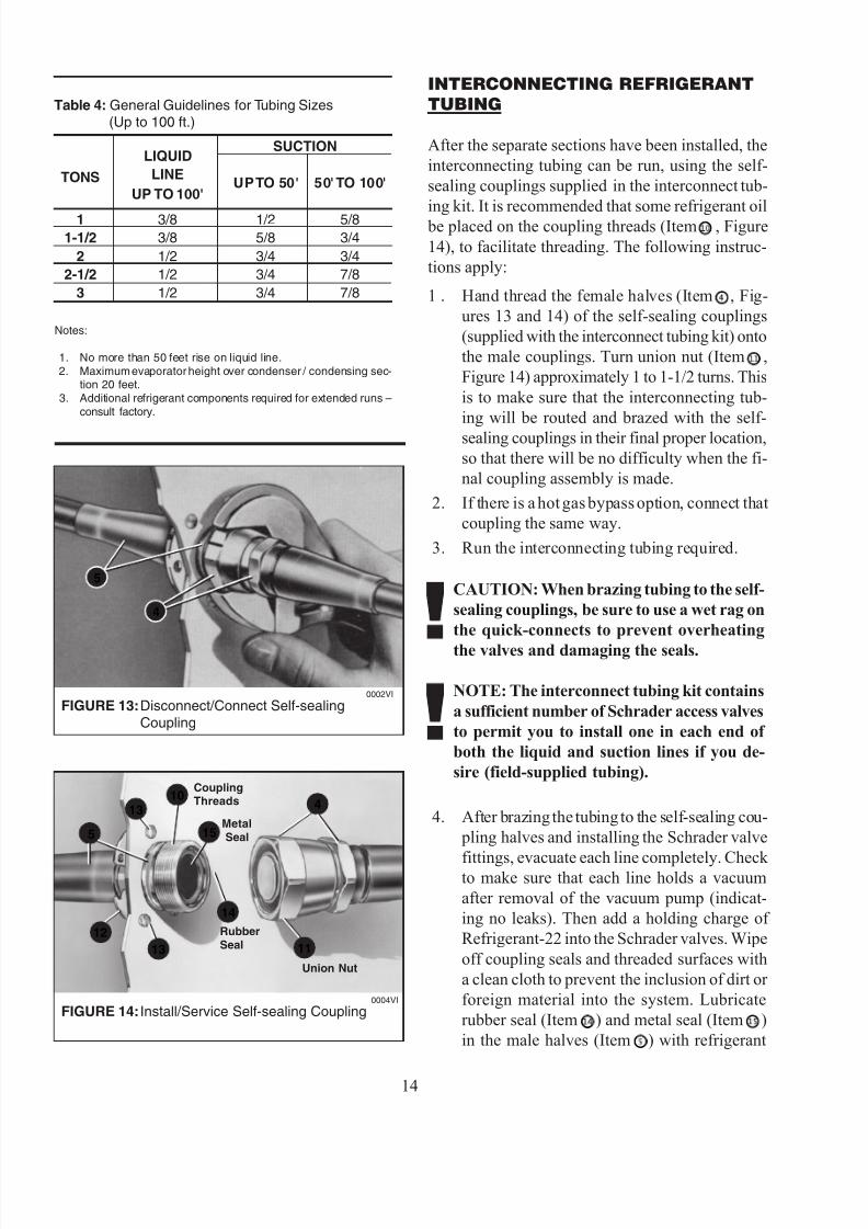
Sizing for the interconnecting refrigerant piping must be determined by the installing contractor using Table4 and industry accepted guidelines. Pipe sizes must
be based on the distance between the sections, eleva-
tion difference and location of the evaporator sectionabove or below the condenser/condensing section.
NOTE: If refrigerant line length will be over100 ft. contact the factory. Additional refrig-erant system components may be necessary.
FIGURE 12: Water Regulating Valve 0007VI
ClockwiseDecreasesPressure
Counter-clockwiseIncreases Pressure
➤ Water Flow
tion on certain unit sizes because there is not enoughspace for the valves to be installed inside the unit.These valves must be adjusted after they are installed.
After the separate sections have been installed, theinterconnecting tubing can be run, using the self-sealing couplings supplied in the interconnect tub-ing kit. It is recommended that some refrigerant oil
be placed on the coupling threads (Item , Figure14), to facilitate threading. The following instruc-tions apply:
1 . Hand thread the female halves (Item , Fig-ures 13 and 14) of the self-sealing couplings(supplied with the interconnect tubing kit) ontothe male couplings. Turn union nut (Item ,Figure 14) approximately 1 to 1-1/2 turns. Thisis to make sure that the interconnecting tub-ing will be routed and brazed with the self-sealing couplings in their final proper location,so that there will be no difficulty when the fi-nal coupling assembly is made.
2. If there is a hot gas bypass option, connect thatcoupling the same way.
3. Run the interconnecting tubing required.
CAUTION: When brazing tubing to the self-sealing couplings, be sure to use a wet rag onthe quick-connects to prevent overheatingthe valves and damaging the seals.
NOTE: The interconnect tubing kit containsa sufficient number of Schrader access valvesto permit you to install one in each end of both the liquid and suction lines if you de-sire (field-supplied tubing).
4. After brazing the tubing to the self-sealing cou- pling halves and installing the Schrader valve
fittings, evacuate each line completely. Check to make sure that each line holds a vacuumafter removal of the vacuum pump (indicat-ing no leaks). Then add a holding charge of Refrigerant-22 into the Schrader valves. Wipeoff coupling seals and threaded surfaces witha clean cloth to prevent the inclusion of dirt or foreign material into the system. Lubricaterubber seal (Item ) and metal seal (Item )in the male halves (Item ) with refrigerant
Table 4: General Guidelines for Tubing Sizes(Up to 100 ft.)
oil. Thread coupling halves together by handto ensure proper mating of threads. Continueto hand-thread each half-coupling to its mat-ing half until resistance is felt (approximately1-1/2 to 1-3/4 turns). Complete the connec-tion of the mating half-couplings with awrench. The suction line couplings (size-12)will be totally engaged after an additional 5-1/2 to 5-3/4 turns. The liquid line couplings(size-8) will be totally engaged after an addi-tional 4-1/2 to 4-3/4 turns.
5. Insulate the interconnecting suction linecompletely with 1/2" thick neoprene tubinginsulation.
6. Add R-22 charge to the system to compen-sate for the additional interconnecting tub-
ing as follows:a. For 3/8" liquid line – add 0.6 oz. per foot
b. For 1/2" liquid line – add 1.2 oz. per footc. For 5/8" liquid line – add 1.8 oz. per footThe suction line should be pitched downwardto the compressor, sloping approximately 1/4"every ten feet to facilitate oil return.
NOTE: “P” traps (field-supplied) are re-quired for all suction line risers every 15 ft.When the evaporator is above the condens-ing section, an inverted “P” trap should beincorporated as close as possible to theevaporator (this minimizes floodback/oilslugging during the off cycle). If the condens-ing section is more than 20 feet above theevaporator, consult the factory for specificrefrigeration components.
CHILLED WATER CONNECTIONS
The chilled water unit uses sweat fittings for inletand outlet. The piping should suffice the system
pressure drop and pump capacity. The air must be bled from the chilled water loop and piping must be cleaned before operating the system.
OPTIONS
Electric heat:Finned tubular heat elements are factory-installedafter the evaporator. The electric heaters are pro-
vided with a limit control switch that turns the heater off if the temperature rises very high under abnor-mal conditions.
Microprocessor controller:The CoolSpot can utilize several different micro-
processor controls. Refer to the specific controlsinstructions sent with the unit.
Humidifier:A steam canister humidifier option can be installedat the factory. The humidifier and canister section islocated in the same compartment as the compressor.
CAUTION: On air-cooled units, care mustbe taken not to expose the humidifier, sup-ply line and drain line to freezing conditions.
Steam is injected into the air stream with a steamdispensing tube. A 1/4" flare fitting is provided onthe side of the unit for the supply water. The hu-midifier drain is connected to the drain connectiontube coming out of the side of the unit. (Refer tosection on drain connection, Page 9.)
NOTE: The condensate pump and conden-sate pan are not adequate to handle the con-
densate and humidifier water volume.
Refer to the installation instructions for the hu-midifier for specific details on the humidifier function and operation.
Hot gas bypass:Hot discharge gas is directed to the inlet of theevaporator after the thermal expansion valve. This
places an artificial load on the system when theconditioned space load drops below the design load.The hot gas bypass valve is set to start modulatingopen at 58 PSIG suction pressure.
Freezestat:This optional control is mounted on the dischargeface of the evaporator coil. If the control senses35°F, it will deactivate the compressor. The evapo-rator blower will continue to run. When the sensedtemperature reaches 37.5°F, the compressor willagain be activated.
Fan Cycling:This option controls the head pressure by cyclingthe condenser blower motor off and on. The effec-tive range of use for this option is down to 40°F. Afan cycling bypass thermostat (optional) is alsoavailable. This is an adjustable thermostat that is
typically set between 65°F and 70°F. This thermo-stat will bypass the fan cycling control above theset point to minimize rapid or quick fan cycling atmoderate outdoor temperatures.
Flooded Condenser:When the outdoor ambient falls, the condensing
pressure falls. This causes the discharge pressureto fall as well. Since the pressure differential acrossthe thermostatic expansion valve port affects therate of refrigerant flow, low head pressure gener-ally causes insufficient refrigerant to be fed to theevaporator. Failure to have sufficient head pressurewill result in low suction pressure and/or icedevaporator coils. The effective range for this op-tion is down to -30°F.
The purpose of a flooded condenser is to hold back enough of the condensed liquid refrigerant so thatsome of the condenser surface is rendered inactive.This reduction of active condensing surface results
in a rise in condensing pressure and sufficient liq-uid line pressure for normal system operation.
A three-way modulating valve and a receiver makeup the flooded condenser refrigerant components.
The valve is placed in the liquid line after the con-denser. The receiver is downstream of the valve.The valve limits the flow of liquid refrigerant fromthe condenser while at the same time regulating theflow of discharge gas around the condenser to thereceiver.
During periods of low ambient operation, the re-ceiver pressure falls until it approaches the settingof the control point of the valve (typically 180 PSIGfor R-22). The valve then throttles to restrict theflow of liquid from the condenser. This raises thecondenser pressure. Since it is the receiver pres-sure that is being maintained, the valve will thenstart to throttle open the discharge port when the
differential between the condensing pressure andthe receiver pressure exceeds 20 PSI. The hot dis-charge gas serves to heat up the cold liquid being
passed from the condenser to the receiver. Thus theliquid reaches the receiver warm and with sufficient
pressure to assure proper expansion valve operation.
The receiver is required to hold all of the excess/additional liquid refrigerant in the system, since therefrigerant will be returned to the receiver whenhigh ambient conditions exist.
In the off-cycle the refrigerant can “migrate” to thecondenser, during periods of low outdoor ambient.On a call for start-up, the evaporator pressure maynot build up to the cut-in point of the low pressurecontrol. The result may be a failure of the compres-
sor to start or to short cycle. To eliminate this po-tential problem, a time delay is added to bypass thelow pressure switch during start-up.
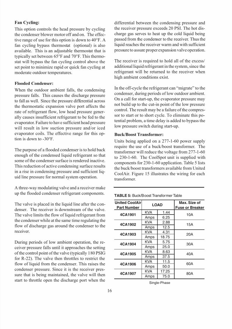
Buck/Boost Transformer:Units being applied on a 277-1-60 power supplyrequire the use of a buck/boost transformer. Thetransformer will reduce the voltage from 277-1-60to 230-1-60. The CoolSpot unit is supplied withcomponents for 230-1-60 application. Table 5 liststhe buck/boost transformers available from UnitedCoolAir. Figure 15 illustrates the wiring for eachtransformer.
and 3-ton units are shipped loose to be field-in-stalled externally.
High pressure water regulating valve:
Water regulating valves with a pressure rating of 350 PSIG are available. These valves are all shippedloose for field installation external to the unit.
THERMOSTAT
Standard units (no heating) are supplied with singlestage thermostats, cool only.
When a programmable thermostat is used, a sixth con-tact must be added to the terminal board. Three con-nections must be made from this sixth contact. . . tothe programmable thermostat, to a ground and tothe 24 volt coil of the evaporator fan motor contactor (K2). (See Figure 18.)
Heat pump units require a heat pump thermostat.Units with electric heat must utilize a single stagecool/single stage heat thermostat.
FIGURE 15: Transformer Wiring 0023CA
K2Evaporator Fan24 Volt Coil
New SixthContact To Be Added
TerminalBoard
Ground
Programmable Thermostat
EvaporatorSectionEnclosure
3
1
2
RG
YY
TC
1
2
FIGURE 18: Adding Sixth Contact0004CA
FIGURE 17: 3-Way Single Circuit 0025CA
CondensingCoil
3-WayValve
WaterIn
WaterOut
Tee
Line Voltage (Available) 277Load Voltage (Output) 230
Solenoid Bypass for Water Regulating Valve:On water-cooled units a N.O. solenoid valve is
placed in the water supply loop. During the “off”cycle the solenoid is opened, thus allowing water to bypass the heat exchanger. The solenoid deviceis rated for 150 PSIG or less.
Chilled Water Valves:Chilled water valves, if supplied by United CoolAir,are typically on/off only. The valve would beshipped loose for installation in the field. The valveis to be mounted in the outlet line of the coil.
Compressor:The standard compressor is reciprocating. Scroll com-
pressors are available in certain sizes and voltages.
Three-way water regulating valve:Three-way water regulating valves modulate thewater flow through the heat exchanger to main-tain the head pressure. The valves for the 2-1/2
FIGURE 16: 2-Way Single Circuit With Bypass 0024CA
A throwaway filter is supplied and is an Under-writers Laboratories Class 2 pleated extended sur-face type. Filter should be checked monthly for dirtaccumulation and changed when necessary. Re-
placement filter must be the same type as originallysupplied.
Field access is attained by opening the return air grille.
NOTE: Unit must be shut off at the discon-
nect switch before the filter is serviced. Be sureto check that the air flow direction arrows onthe filter points in the right direction.
checked to see how much loss of operating perfor-mance has occurred. If a 10% or greater change hasoccurred it would be beneficial to clean the heatexchanger.
A 5% solution of Phosphoric Acid or Oxalic Acidcan be considered for cleaning. However, there areseveral commercially available environmentallysafe products on the market that will do an excel-lent job. Contact your local wholesaler for avail-ability. Follow all safety guidelines published bythe cleaner manufacturer.
There is a safety concern whenever using any fluidat elevated temperatures. The cleaner manufactur-
ers recommend using the cleaners at 120°F or lower.Since the heat exchanger might be in operation just
prior to the cleaning, it should be cooled to lower than the 120°F threshold. Due to the ability of theheat exchanger mass to hold heat, this may take a
period of time. If possible, run cool water throughthe unit to help dissipate some of the heat.
Check each component as to the suitability of run-ning the cleaner through them. For example, strain-ers may not be good to run the cleaner through.However, while there cleaning the heat exchanger,it would be a good time to also do a clean and check on the strainer.
NOTE: Do not chemically clean a refriger-ant circuit.
1. Record performance values (Ref. followingcharts). Turn off the fluid source.
2. Cool the heat exchanger, if above 120°F.
3. Close the valves to and from the fluid circuitloop.
4. Open the drain valve and drain all fluid fromthe heat exchanger.
5. Back flush the heat exchanger to remove anyloose particles.
CLEANING THE WATER-COOLEDCONDENSER
Cleaning a water-cooled condenser helps to im- prove the heat transfer rate, reduce operation cost,restore efficiency, prolong heat exchanger life andreduce pressure drop pumping cost. Deposits fromwater or water treatments, such as scale, lime, rustor mud, are removed.
Each installation is unique; therefore, the fluid qual-ity and operating conditions will dictate when theheat exchanger needs to be cleaned.
As a general practice it is beneficial to record thedetails on temperatures entering and leaving the heatexchanger and the pressure drop across the heat ex-changer when first installed (see Page 12, “Hook-Up”). After a period of time these values can be
UNIT FILTER SIZE/TYPE QUANTITY
Standard 20 x 20 x 1 1ThrowawayWith 18 x 20 x1 1MiniMarvel Throwaway
Air-cooled self-contained units are provided withadjustable belt drive blower packages for the con-densing section. Check that the blower wheel is tighton the shaft and does not contact the housing. Bear-
ings are permanently sealed, but should be checked periodically for signs of wear. Check for restric-tions or foreign material in the air circuit.
The drive may be adjusted for different static pres-sures. If such an adjustment is made, check that themotor current draw does not exceed the motor nameplate current by more than 10%.
On units with three-phase fan motors, check for proper blower rotation at start-up. If theyrun backwards, turn off the power, inter-change two of the incoming power leads,then reapply power.
BLOWER MOTORS
All blower motors are equipped with thermal over-load protectors.
CAUTION: Before servicing, open discon-nects to unit, as motor will start when auto-matic thermal overload resets.
BLOWER SPEED ADJUSTMENT
Blower speed may be changed by adjusting thevariable diameter sheave provided on the blower drive motor. Sheave may be adjusted by remov-ing the belt and loosening the setscrew located in
the hub of the outer flange. With the setscrew loos-ened, the flange may be turned clockwise to in-crease blower speed and counter-clockwise to re-duce blower speed.
CAUTION: Setscrew must be positioned di-rectly above a flat section of the threaded sheaveshaft before tightening to hold adjustment.
NOTE: Verify that the motor current drawdoes not exceed the motor nameplate cur-rent by more than 10%.
BLOWER MOTOR LUBRICABLOWER MOTOR LUBRICABLOWER MOTOR LUBRICABLOWER MOTOR LUBRICABLOWER MOTOR LUBRICA TIONTIONTIONTIONTION
Motor manufacturers indicate that motors never need relubrication, but if units run continuously,it is recommend that they be re-lubricated every5500 hours (7-8 months). If unit motors are run ina cyclical manner, lubrication is recommended ev-ery 5 years.
If unit has been inactive or in storage for over ayear, re-lubricate before starting.
Use Chevron SRI #2 lubricant or equivalent in thefollowing quantities: 0.6 cu. in. or 2 teaspoons. Keepgrease clean, and do not mix dissimilar greases.
Clean area around fitting. Remove purge plug (only
on larger motors) for greasing, and replace after atleast 20 minutes of operation after greasing. For safety, we recommend relubricating while the mo-tor is stopped.
Overgreasing, either in quantity or speed of injec-tion, can cause premature bearing failure. Applythe recommended quantity of grease gradually, tak-ing at least one minute to do so. Rotate the motor while applying the grease.
BELTS
Drive belts should be examined periodically for wear and for correct tension. Too tight a belt cancause bearing wear; too loose a belt will cause slip-
page. If the two legs of the belt are pressed in mid-way between the pulley and the sheave, resultingin 1-1/2" to 1" of movement, the belt is tensioned
properly. Belt tension can be adjusted by means of the adjusting bolt, which requires loosening of anut to move the motor and change belt position.
REFRIGERANT SYSTEMS
All United CoolAir systems contain a liquid linesight glass. If bubbles appear in the sight glass, the
system is either undercharged with refrigerant, or there may be a restriction in the liquid line upstreamof the sight glass. However, the appearance of
bubbles may be normal in units with hot gas bypass.
The sight glass contains a moisture indicator whichchanges color when moisture is present in the sys-tem. If sight glass appearance is abnormal, servic-ing is required.
EVAPORATOR AND AIR-COOLEDCONDENSER COILS
Check semimonthly the condition of the face of boththe evaporator and condenser coils.
A dirty condenser coil will cause high condensing
pressures, resulting in higher power consumptionand possibly system shut-down by high-pressuresafety control. A dirty evaporator coil will reduceunit capacity and eventually will cause shut-down
1. Before starting unit, make sure electrical power has been turned on for a minimum of 24 hours.
This ensures that any liquid refrigerant is“driven” out of the crankcase.
2. For water-cooled units, make sure condenser water is available. Open all stop valves. Verifythat cooling tower is functioning, if this is thesource of condensing water supply. Bleed theair from the loop.
3. The following sequence is based on the unit being controlled by a room thermostat. If an-
other control type is being utilized, referenceto the instructions for that device may be re-quired.
a. Raise thermostat setpoint to highest level.
b. Set System switch to “OFF” position.
c. Set Fan switch to the “AUTO” position.
d. Moving the Fan switch to the “ON” posi-tion should cause the evaporator blower mo-tor to run. Moving the Fan Switch back to“AUTO” should stop the blower.
e. Move the System switch to the “COOL” po-sition. Slowly lower the thermostat settingto call for cooling. The evaporator blower should start (assumes Fan switch set to“AUTO”) and the compressor should start.
f. Set room thermostat at desired space tem- perature. Set the Fan switch to “AUTO”or “ON”. The unit will cycle as required to
maintain conditions.
4. Chill water sequence is the same as above, ex-cept compressor activation is replaced by thechill water valve function.
5. Heat pump cooling sequence is the same as
above, except the reversing valve will also beactivated when the compressor cycle is started.
HEATING SEQUENCE OF OPERATION(OTHER THAN HEAT PUMP)
1. The following sequence is based on the unit being controlled by a room thermostat. If an-other control type is being utilized, referenceto the instructions for that device may be re-quired.
a. Lower thermostat setpoint to the lowestlevel.
b. Set System switch to “OFF” position.
c. Set Fan switch to “AUTO” position.
d. Moving the Fan switch to the “ON” posi-tion should cause the evaporator blower mo-tor to run. Moving the Fan switch back to“AUTO” should stop the blower.
e. Move the System switch to the “HEAT” po-sition. Slowly raise the thermostat settingto call for heating. The evaporator blower should start (assumes Fan switch set to“AUTO”) and the electric heating elementwill be activated.
f. Set room thermostat at desired space tem- perature. Set the fan switch to “AUTO” or “ON”. The unit will cycle as required tomaintain conditions.
1. Before starting unit, make sure electrical power
has been turned on for a minimum of 24 hours.This assures that any liquid refrigerant is“driven” out of the crankcase.
2. For water-cooled units, make sure condenser water is available. Open all stop valves. Verifythat cooling tower is functioning, if this is thesource of condensing water supply. Bleed theair from the loop.
3. The following sequence is based on the unit being controlled by a room thermostat. If an-other control type is being utilized, refer-ence to the instructions for that device may
be required.
a. Lower thermostat setpoint to the lowestlevel.
b. Set System switch to “OFF” position.
c. Set Fan switch to “AUTO” position.
d. Moving the Fan switch to the “ON” posi-tion should cause the evaporator blower mo-tor to run. Moving the Fan switch back to“AUTO” should stop the blower.
e. Move the System switch to the “HEAT” po-sition. Slowly raise the thermostat settingto call for heating. The evaporator blower should start (assumes Fan switch set to“AUTO”) and the compressor will start.
f. Set room thermostat at desired space tem- perature. Set the Fan switch to “AUTO”or “ON”. The unit will cycle as required tomaintain conditions.
WARNING: Turn OFF power to unit before conducting any troubleshooting, unless the tests youare performing require system operation. Keep hands, clothing and tools clear of electrical ter-minals and rotating components. It can be difficult to service equipment located in the ceiling.Make sure your footing is stable.
NOTE: For operating and troubleshooting instruction for Microprocessor Controller and hu-midifier, refer to operating instructions that accompany this unit.
ITEM PROBLEM PROBABLE CAUSE SOLUTIONCODE
1 Control is erratic. Wired improperly, Check wiring connectionsconnected or broken. against schematic diagram.
2
Evaporator coil ices. Usually caused by lack Check filter: clean or replace if necessary.of proper air quantity. Check for obstruction across coil. Check
correct rotation of evaporator blower.
Low return air Raise return air setpoint.temperature.
Low refrigerant charge. Check DX system for correct operation.
3
Blower fails to start. Power failure. Check main voltage power source andinput cable.
Defective contactor. Repair or replace.
Overload tripped. Reset and check cause.
Drain pan overflow Verify that the condensate pan is
switch open. draining properly.
4
Compressor fails to start. Thermostat set too high. Adjust to desired temperature.
Power Failure. Check main voltage power sourceand input cable.
Compressor internal Check compressor for short circuit or groundprotector open. or loss of phase.
Loss of refrigerant Repair leak and recharge refrigerant system.charge.
Head pressure too high Check condenser for obstructions.(high pressure switch Manually reset thermostat.open.)
Thermostat set too low. Adjust thermostat to the desired temperature.
Overheat switch open. Insufficient air across the heater elements.Check for obstructed or dirty filter.
Heater elements burned Check continuity with an ohm meter. Replaceout. heater element.
13
Water carryover. Liquid line temperature. Adjust condensing temperature tospecifications and reduce excessivesubcooling.
Dirty coil. Clean the coil.
Excessive air. Reduce cfm to unit specifications.
14
Compressor will Compressor out on high See Item 8 on high head pressure.not operate when head pressure.cooling is called for.
High pressure switch Check high pressure switch fordefective. continuity and replace if defective.
Low head pressure. Clean filter or recharge the system.
Low pressure switch Check low pressure switch
defective. for continuity.
Water sensor in Check for restriction in condensatecondensate drain line or condensate pumpdrain pan senses high operation.condensate level.System shutdown.
15
Main blower will not Power not on. Check the circuit breaker.operate.
Overload tripped on Determine cause and manually test.motor.
NOTE: For operating and Troubleshooting Instruction for microprocessor controller and hu-midifier refer to Operating Instructions that accompany this unit.