Pipe clamps offered in this section are designed for support and attachment of pipe to structural members. A wide range of pipe clamps are available for various applications. Materials Carbon Steel is used in the manufacturing of riser and pipe clamps. Stainless Steel and other materials are available. Finishes The standard finishes for mechanical supports are plain steel (oil coated) sometimes referred to as black and Electro- Galvanized Zinc (ASTM B 633 SC3). Hot-Dip Galvanized After Fabrication (ASTM A 123), Red Primer, Plastic Coating, DURA-GREEN™, DURA-COPPER™ and other special coatings are available upon request. Note: Due to the design of some products, (threads, connecting hardware, swivels, etc.) items may or may not be uniformly coated with special finishes. In some cases, the hanger itself may be coated, however, the hardware may be supplied Electro-Plated, Copper Plated, or in Stainless Steel. Recommended Torque (Pipe Clamp Hardware) 1 /4”-20 5 /16”-18 3 /8”-16 1 /2”-13 5 /8”-11 3 /4”-10 & larger 6 ft/lbs (8 Nm) 11 ft/lbs (19 Nm) 19 ft/lbs (26 Nm) 50 ft/lbs (68 Nm) 65 ft/lbs (88 Nm) 75 ft/lbs (101 Nm) Approvals (as noted) Items in this section are Underwriters Laboratories Listed, Factory Mutual Approved, and comply with Federal Specification WW-H-171E & A-A-1192A or Manufacturers Standardization Society ANSI/MSS SP-69 & SP-58. All pipe hangers and supports in this section are sized to fit schedule 40/80 pipe unless otherwise noted. Some steel items may be specially fabricated to fit other pipe diameters i.e. ductile iron, cast iron, etc. Select pipe O.D. from charts on pages 294 thru 300. Pipe Clamps Pipe Clamps 74 All dimensions in charts and on drawings are in inches. Dimensions shown in parentheses are in millimeters unless otherwise specified.
Transcript
Pipe clamps offered in this section are designed for support and attachment of pipe to structural members. A widerange of pipe clamps are available for various applications.
MaterialsCarbon Steel is used in the manufacturing of riser and pipe clamps. Stainless Steel and other materials are available.
FinishesThe standard finishes for mechanical supports are plain steel (oil coated) sometimes referred to as black and Electro-Galvanized Zinc (ASTM B 633 SC3). Hot-Dip Galvanized After Fabrication (ASTM A 123), Red Primer, Plastic Coating,DURA-GREEN™, DURA-COPPER™ and other special coatings are available upon request.
Note: Due to the design of some products, (threads, connecting hardware, swivels, etc.) items may or may not beuniformly coated with special finishes. In some cases, the hanger itself may be coated, however, the hardware maybe supplied Electro-Plated, Copper Plated, or in Stainless Steel.
Approvals (as noted)Items in this section are Underwriters Laboratories Listed, Factory Mutual Approved, and comply with FederalSpecification WW-H-171E & A-A-1192A or Manufacturers Standardization Society ANSI/MSS SP-69 & SP-58.
All pipe hangers and supports in this section are sized to fit schedule 40/80 pipe unless otherwise noted. Some steelitems may be specially fabricated to fit other pipe diameters i.e. ductile iron, cast iron, etc. Select pipe O.D. fromcharts on pages 294 thru 300.
Pip
e Clam
ps
Pipe Clamps
74
All dimensions in charts and on drawings are in inches. Dimensions shown in parentheses are in millimeters unless otherwise specified.
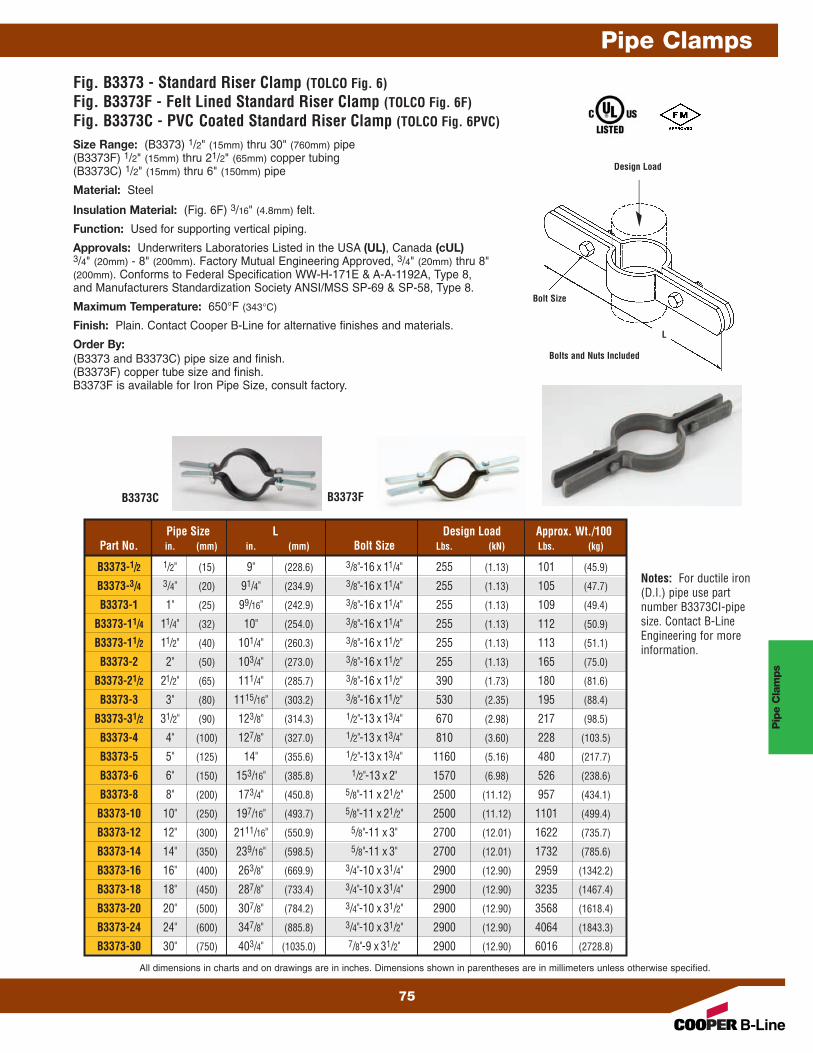
Fig. B3373 - Standard Riser Clamp (TOLCO Fig. 6)Fig. B3373F - Felt Lined Standard Riser Clamp (TOLCO Fig. 6F)Fig. B3373C - PVC Coated Standard Riser Clamp (TOLCO Fig. 6PVC)
Bolts and Nuts Included
Bolt Size
L
Pipe Size L Design Load Approx. Wt./100Part No. in. (mm) in. (mm) Bolt Size Lbs. (kN) Lbs. (kg)
Approvals: Underwriters Laboratories Listed in the USA (UL), Canada (cUL)3/4" (20mm) - 8" (200mm). Factory Mutual Engineering Approved, 3/4" (20mm) thru 8"(200mm). Conforms to Federal Specification WW-H-171E & A-A-1192A, Type 8,and Manufacturers Standardization Society ANSI/MSS SP-69 & SP-58, Type 8.
Maximum Temperature: 650°F (343°C)
Finish: Plain. Contact Cooper B-Line for alternative finishes and materials.
Order By:(B3373 and B3373C) pipe size and finish.(B3373F) copper tube size and finish.B3373F is available for Iron Pipe Size, consult factory.
Notes: For ductile iron(D.I.) pipe use partnumber B3373CI-pipesize. Contact B-LineEngineering for moreinformation.
All dimensions in charts and on drawings are in inches. Dimensions shown in parentheses are in millimeters unless otherwise specified.
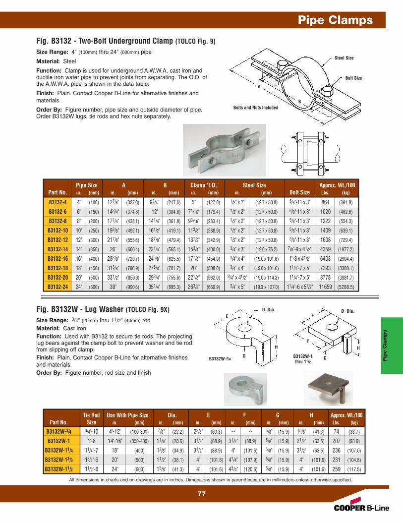
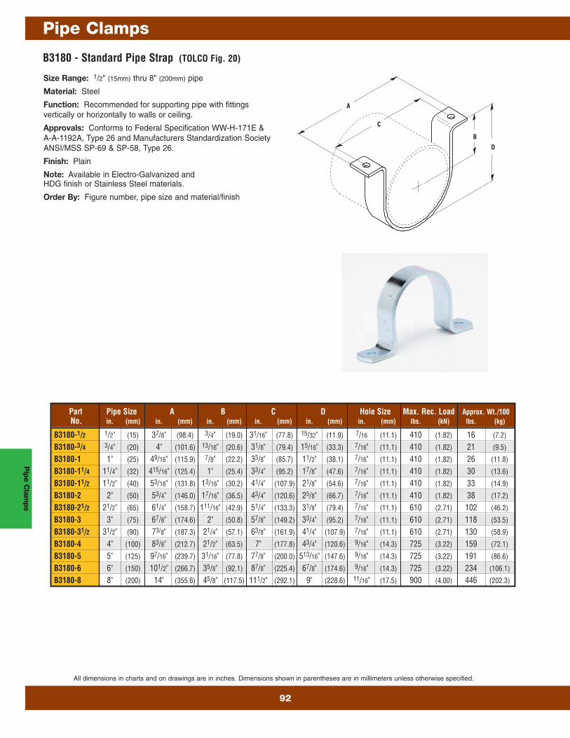
Size Range: 4" (100mm) thru 24" (600mm) pipe
Material: Steel
Function: Clamp is used for underground A.W.W.A. cast iron andductile iron water pipe to prevent joints from separating. The O.D. ofthe A.W.W.A. pipe is shown in the data table.
Finish: Plain. Contact Cooper B-Line for alternative finishes andmaterials.
Order By: Figure number, pipe size and outside diameter of pipe.Order B3132W lugs, tie rods and hex nuts separately.
Size Range: 3/4" (20mm) thru 11/2" (40mm) rodMaterial: Cast IronFunction: Used with B3132 to secure tie rods. The projecting lug bears against the clamp bolt to prevent washer and tie rodfrom slipping off clamp.Finish: Plain. Contact Cooper B-Line for alternative finishesand materials.Order By: Figure number, rod size and finish
Fig. B3132W - Lug Washer (TOLCO Fig. 9X)
Bolts and Nuts Included
Steel Size
Bolt Size
D Dia.
B3132W-3/4 B3132W-1thru 11/2
D Dia.E E
H H
GG
F
A
B
Pipe Size A B Clamp ‘I.D.’ Steel Size Approx. Wt./100Part No. in. (mm) in. (mm) in. (mm) in. (mm) in. (mm) Bolt Size Lbs. (kg)
B3132-4 4" (100) 127/8" (327.0) 93/4" (247.6) 5" (127.0) 1/2" x 2" (12.7 x 50.8) 5/8"-11 x 3" 864 (391.9)
B3132-6 6" (150) 143/4" (374.6) 12" (304.8) 71/16" (179.4) 1/2" x 2" (12.7 x 50.8) 5/8"-11 x 3" 1020 (462.6)
B3132-8 8" (200) 171/4" (438.1) 141/4" (361.9) 93/16" (233.4) 1/2" x 2" (12.7 x 50.8) 5/8"-11 x 3" 1222 (554.3)
B3132-10 10" (250) 193/8" (492.1) 161/2" (419.1) 113/8" (288.9) 1/2" x 2" (12.7 x 50.8) 5/8"-11 x 3" 1409 (639.1)
B3132-12 12" (300) 217/8" (555.6) 187/8" (479.4) 131/2" (342.9) 1/2" x 2" (12.7 x 50.8) 5/8"-11 x 3" 1608 (729.4)
B3132-14 14" (350) 26" (660.4) 221/4" (565.1) 153/4" (400.0) 3/4" x 3" (19.0 x 76.2) 7/8"-9 x 41/2" 4359 (1977.2)
B3132-16 16" (400) 283/8" (720.7) 245/8" (625.5) 177/8" (454.0) 3/4" x 4" (19.0 x 101.6) 1"-8 x 41/2" 6403 (2904.4)
B3132-18 18" (450) 313/8" (796.9) 275/8" (701.7) 20" (508.0) 3/4" x 4" (19.0 x 101.6) 11/4"-7 x 5" 7293 (3308.1)
B3132-20 20" (500) 331/2" (850.9) 293/4" (755.6) 221/8" (562.0) 3/4" x 41/2" (19.0 x 114.3) 11/4"-7 x 5" 8778 (3981.7)
B3132-24 24" (600) 39" (990.6) 351/4" (895.3) 263/8" (669.9) 3/4" x 5" (19.0 x 127.0) 11/4"-6 x 51/2" 11659 (5288.5)
Tie Rod Use With Pipe Size Dia. E F G H Approx. Wt./100Part No. Size in. (mm) in. (mm) in. (mm) in. (mm) in. (mm) in. (mm) Lbs. (kg)
Function: Clamp is used for underground A.W.W.A. cast iron andductile iron water pipe to prevent joints from separating. The O.D. of theA.W.W.A. pipe is shown in the data table.
Approvals: Conforms to National Fire Protection Association (NFPA)Pamphlet 24, 4" (100mm) thru 12" (300mm) pipe sizes.
Finish: Plain. Contact Cooper B-Line for alternative finishes andmaterials.
Order By: Figure number, pipe size andoutside diameter of pipe.
Order B3134W plate washers, tie rodsand hex nuts separately.
A
B
Part Pipe Size A B Bolt B3134 Washer Size) Approx. Wt./100No. in. (mm) in. (mm) in. (mm) Size lbs. (kg)
Finish: Plain. Contact Cooper B-Line for alternative finishes and materials.
Order By: Figure number, rod size and finish
C
A A
B
Pip
e Clam
ps
Pipe Clamps
78
All dimensions in charts and on drawings are in inches. Dimensions shown in parentheses are in millimeters unless otherwise specified.
Pip
e C
lam
ps
Pipe Clamps
All dimensions in charts and on drawings are in inches. Dimensions shown in parentheses are in millimeters unless otherwise specified.
79
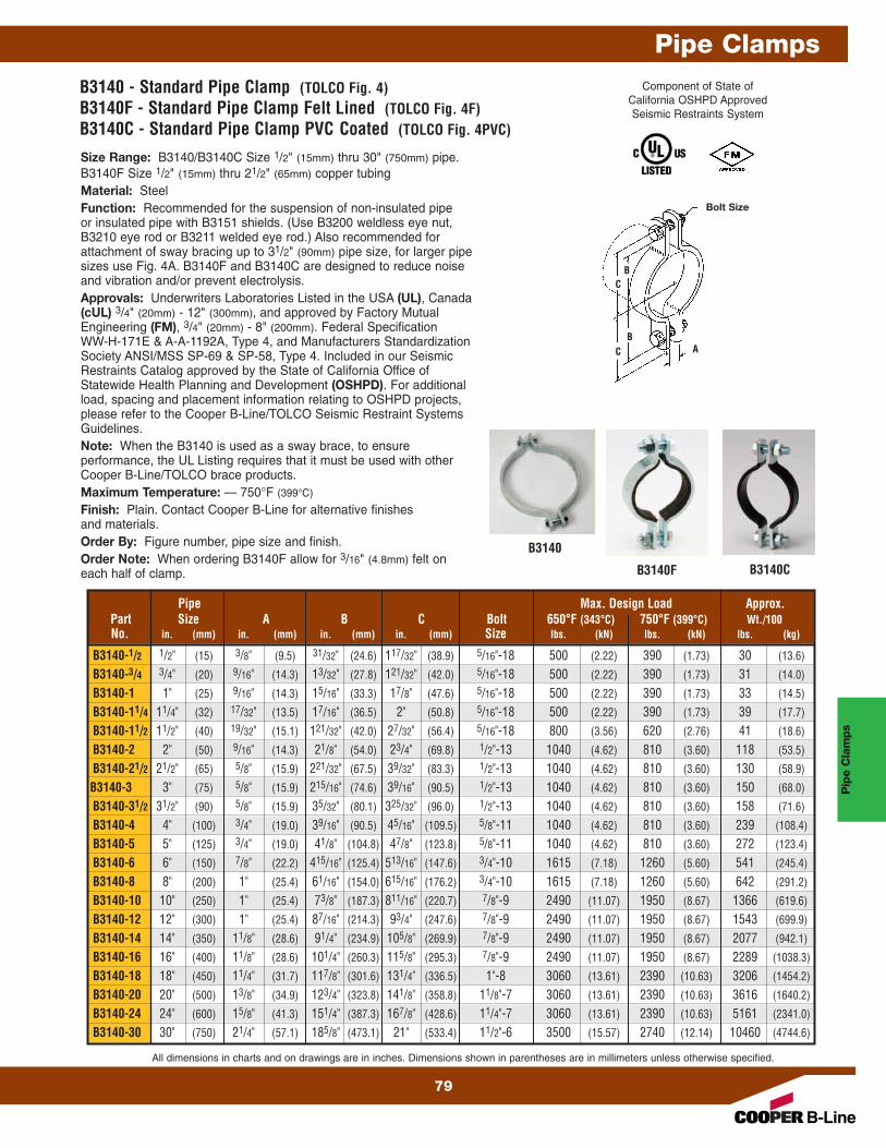
B3140 - Standard Pipe Clamp (TOLCO Fig. 4)B3140F - Standard Pipe Clamp Felt Lined (TOLCO Fig. 4F)B3140C - Standard Pipe Clamp PVC Coated (TOLCO Fig. 4PVC)
Size Range: B3140/B3140C Size 1/2" (15mm) thru 30" (750mm) pipe.B3140F Size 1/2" (15mm) thru 21/2" (65mm) copper tubingMaterial: SteelFunction: Recommended for the suspension of non-insulated pipeor insulated pipe with B3151 shields. (Use B3200 weldless eye nut,B3210 eye rod or B3211 welded eye rod.) Also recommended forattachment of sway bracing up to 31/2" (90mm) pipe size, for larger pipesizes use Fig. 4A. B3140F and B3140C are designed to reduce noiseand vibration and/or prevent electrolysis.Approvals: Underwriters Laboratories Listed in the USA (UL), Canada(cUL) 3/4" (20mm) - 12" (300mm), and approved by Factory MutualEngineering (FM), 3/4" (20mm) - 8" (200mm). Federal SpecificationWW-H-171E & A-A-1192A, Type 4, and Manufacturers StandardizationSociety ANSI/MSS SP-69 & SP-58, Type 4. Included in our SeismicRestraints Catalog approved by the State of California Office ofStatewide Health Planning and Development (OSHPD). For additionalload, spacing and placement information relating to OSHPD projects,please refer to the Cooper B-Line/TOLCO Seismic Restraint SystemsGuidelines.Note: When the B3140 is used as a sway brace, to ensureperformance, the UL Listing requires that it must be used with otherCooper B-Line/TOLCO brace products.Maximum Temperature: — 750°F (399°C)
Finish: Plain. Contact Cooper B-Line for alternative finishesand materials.Order By: Figure number, pipe size and finish.Order Note: When ordering B3140F allow for 3/16" (4.8mm) felt oneach half of clamp.
C
C
A
Bolt Size
B
B
Pipe Max. Design Load Approx.Part Size A B C Bolt 650°F (343°C) 750°F (399°C) Wt./100No. in. (mm) in. (mm) in. (mm) in. (mm) Size lbs. (kN) lbs. (kN) lbs. (kg)
Component of State ofCalifornia OSHPD ApprovedSeismic Restraints System
B3140
B3140F B3140C
Pip
e Clam
ps
Pipe Clamps
80
All dimensions in charts and on drawings are in inches. Dimensions shown in parentheses are in millimeters unless otherwise specified.
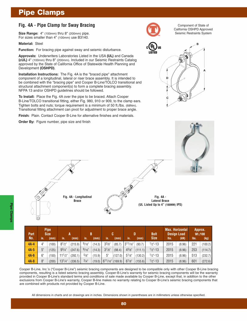
Fig. 4A - Pipe Clamp for Sway Bracing
Size Range: 4" (100mm) thru 8" (200mm) pipe.For sizes smaller than 4" (100mm) use B3140.
Material: Steel
Function: For bracing pipe against sway and seismic disturbance.
Approvals: Underwriters Laboratories Listed in the USA (UL) and Canada(cUL) 4" (100mm) thru 8" (200mm). Included in our Seismic Restraints Catalogapproved by the State of California Office of Statewide Health Planning andDevelopment (OSHPD).
Installation Instructions: The Fig. 4A is the "braced pipe" attachmentcomponent of a longitudinal, lateral or riser brace assembly. It is intended tobe combined with the "bracing pipe" and Cooper B-Line/TOLCO transitional andstructural attachment component(s) to form a complete bracing assembly.NFPA 13 and/or OSHPD guidelines should be followed.
To Install: Place the Fig. 4A over the pipe to be braced. Attach CooperB-Line/TOLCO transitional fitting, either Fig. 980, 910 or 909, to the clamp ears.Tighten bolts and nuts; torque requirement is a minimum of 50 ft./lbs. (68Nm).Transitional fitting attachment can pivot for adjustment to proper brace angle.
Finish: Plain. Contact Cooper B-Line for alternative finishes and materials.
Order By: Figure number, pipe size and finish
C
D
A
B
Pipe Max. Horizontal Approx.Part Size A B C D Bolt Design Load Wt./100No. in. (mm) in. (mm) in. (mm) in. (mm) in. (mm) Size lbs. (kN) lbs. (kg)
Component of State ofCalifornia OSHPD ApprovedSeismic Restraints System
Cooper B-Line, Inc.’s (“Cooper B-Line”) seismic bracing components are designed to be compatible only with other Cooper B-Line bracingcomponents, resulting is a listed seismic bracing assembly. Cooper-B-Line’s warranty for seismic bracing components will be the warrantyprovided in Cooper B-Line’s standard terms and conditions of sale made available by Cooper B-Line, except that, in addition to the otherexclusions from Cooper B-Line’s warranty, Cooper B-line makes no warranty relating to Cooper B-Line’s seismic bracing components thatare combined with products not provided by Cooper B-Line.
Fig. 4A -Lateral Brace
(UL Listed Up to 4” (100MM) IPS)
Fig. 4A - LongitudinalBrace
™
Pip
e C
lam
ps
Pipe Clamps
All dimensions in charts and on drawings are in inches. Dimensions shown in parentheses are in millimeters unless otherwise specified.
81
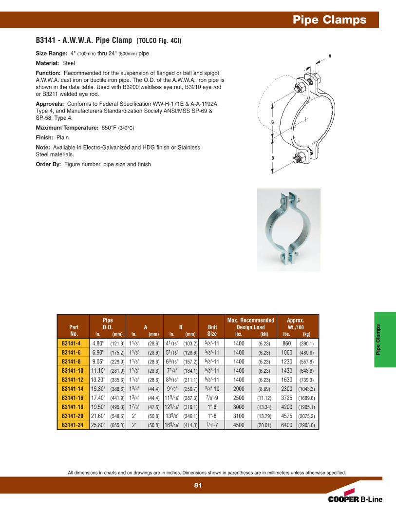
B3141 - A.W.W.A. Pipe Clamp (TOLCO Fig. 4CI)
Size Range: 4" (100mm) thru 24" (600mm) pipe
Material: Steel
Function: Recommended for the suspension of flanged or bell and spigotA.W.W.A. cast iron or ductile iron pipe. The O.D. of the A.W.W.A. iron pipe isshown in the data table. Used with B3200 weldless eye nut, B3210 eye rodor B3211 welded eye rod.
Approvals: Conforms to Federal Specification WW-H-171E & A-A-1192A,Type 4, and Manufacturers Standardization Society ANSI/MSS SP-69 &SP-58, Type 4.
Maximum Temperature: 650°F (343°C)
Finish: Plain
Note: Available in Electro-Galvanized and HDG finish or StainlessSteel materials.
Order By: Figure number, pipe size and finishB
A
B
Pipe Max. Recommended Approx.Part O.D. A B Bolt Design Load Wt./100No. in. (mm) in. (mm) in. (mm) Size lbs. (kN) lbs. (kg)
All dimensions in charts and on drawings are in inches. Dimensions shown in parentheses are in millimeters unless otherwise specified.
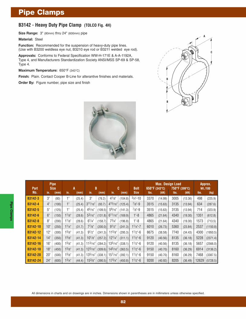
B3142 - Heavy Duty Pipe Clamp (TOLCO Fig. 4H)
Size Range: 3" (80mm) thru 24" (600mm) pipe
Material: Steel
Function: Recommended for the suspension of heavy-duty pipe lines.(Use with B3200 weldless eye nut, B3210 eye rod or B3211 welded eye rod).
Approvals: Conforms to Federal Specification WW-H-171E & A-A-1192A,Type 4, and Manufacturers Standardization Society ANSI/MSS SP-69 & SP-58,Type 4.
Maximum Temperature: 650°F (343°C)
Finish: Plain. Contact Cooper B-Line for alterantive finishes and materials.
Order By: Figure number, pipe size and finish
C
A
B
B
Pipe Max. Design Load Approx.Part Size A B C Bolt 650°F (343°C) 750°F (399°C) Wt./100No. in. (mm) in. (mm) in. (mm) in. (mm) Size lbs. (kN) lbs. (kN) lbs. (kg)
All dimensions in charts and on drawings are in inches. Dimensions shown in parentheses are in millimeters unless otherwise specified.
83
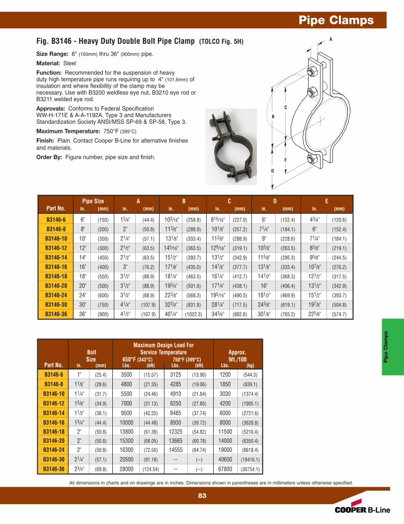
Size Range: 6" (150mm) thru 36" (900mm) pipe.
Material: Steel
Function: Recommended for the suspension of heavyduty high temperature pipe runs requiring up to 4" (101.6mm) ofinsulation and where flexibility of the clamp may benecessary. Use with B3200 weldless eye nut, B3210 eye rod orB3211 welded eye rod.
Approvals: Conforms to Federal Specification WW-H-171E & A-A-1192A, Type 3 and ManufacturersStandardization Society ANSI/MSS SP-69 & SP-58, Type 3.
Maximum Temperature: 750°F (399°C)
Finish: Plain. Contact Cooper B-Line for alternative finishesand materials.
All dimensions in charts and on drawings are in inches. Dimensions shown in parentheses are in millimeters unless otherwise specified.
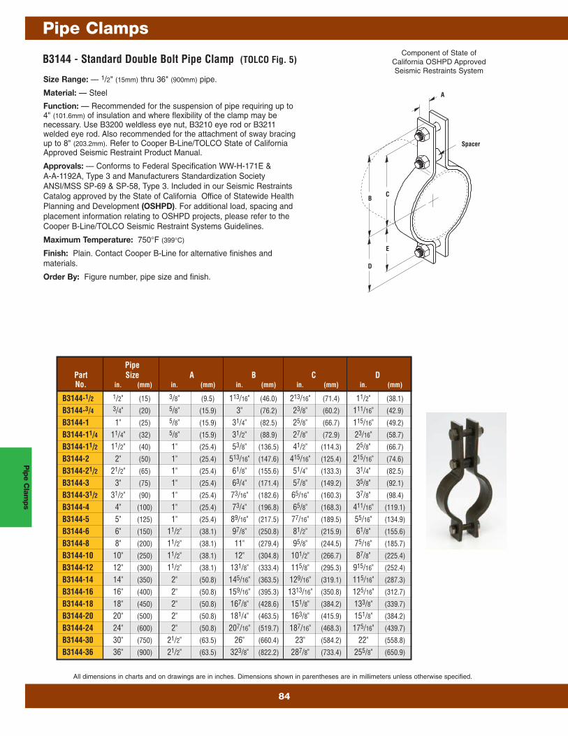
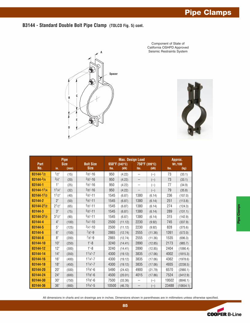
B3144 - Standard Double Bolt Pipe Clamp (TOLCO Fig. 5)
Size Range: — 1/2" (15mm) thru 36" (900mm) pipe.
Material: — Steel
Function: — Recommended for the suspension of pipe requiring up to4" (101.6mm) of insulation and where flexibility of the clamp may benecessary. Use B3200 weldless eye nut, B3210 eye rod or B3211welded eye rod. Also recommended for the attachment of sway bracingup to 8" (203.2mm). Refer to Cooper B-Line/TOLCO State of CaliforniaApproved Seismic Restraint Product Manual.
Approvals: — Conforms to Federal Specification WW-H-171E &A-A-1192A, Type 3 and Manufacturers Standardization SocietyANSI/MSS SP-69 & SP-58, Type 3. Included in our Seismic RestraintsCatalog approved by the State of California Office of Statewide HealthPlanning and Development (OSHPD). For additional load, spacing andplacement information relating to OSHPD projects, please refer to theCooper B-Line/TOLCO Seismic Restraint Systems Guidelines.
Maximum Temperature: 750°F (399°C)
Finish: Plain. Contact Cooper B-Line for alternative finishes andmaterials.
Order By: Figure number, pipe size and finish.D
C
Spacer
E
A
B
PipePart Size A B C DNo. in. (mm) in. (mm) in. (mm) in. (mm) in. (mm)
Component of State ofCalifornia OSHPD ApprovedSeismic Restraints System
D
C
Spacer
E
A
B
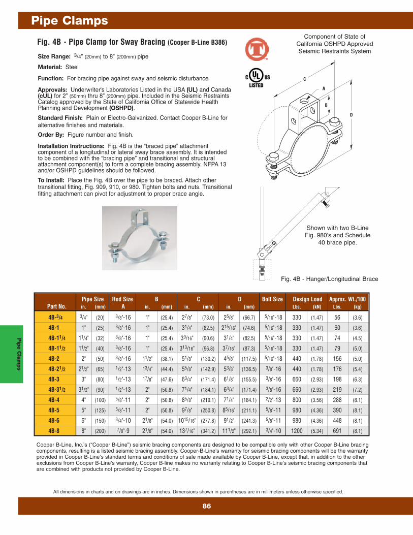
Size Range: 3/4” (20mm) to 8” (200mm) pipe
Material: Steel
Function: For bracing pipe against sway and seismic disturbance
Approvals: Underwriter's Laboratories Listed in the USA (UL) and Canada(cUL) for 2” (50mm) thru 8” (200mm) pipe. Included in the Seismic RestraintsCatalog approved by the State of California Office of Statewide HealthPlanning and Development (OSHPD).
Standard Finish: Plain or Electro-Galvanized. Contact Cooper B-Line foralternative finishes and materials.
Order By: Figure number and finish.
Installation Instructions: Fig. 4B is the “braced pipe” attachmentcomponent of a longitudinal or lateral sway brace assembly. It is intendedto be combined with the “bracing pipe” and transitional and structuralattachment component(s) to form a complete bracing assembly. NFPA 13and/or OSHPD guidelines should be followed.
To Install: Place the Fig. 4B over the pipe to be braced. Attach othertransitional fitting, Fig. 909, 910, or 980. Tighten bolts and nuts. Transitionalfitting attachment can pivot for adjustment to proper brace angle.
Component of State ofCalifornia OSHPD ApprovedSeismic Restraints System
Shown with two B-LineFig. 980’s and Schedule
40 brace pipe.
Fig. 4B - Hanger/Longitudinal Brace
B
D
C
A
Pip
e Clam
ps
Pipe Clamps
86
All dimensions in charts and on drawings are in inches. Dimensions shown in parentheses are in millimeters unless otherwise specified.
Cooper B-Line, Inc.’s (“Cooper B-Line”) seismic bracing components are designed to be compatible only with other Cooper B-Line bracingcomponents, resulting is a listed seismic bracing assembly. Cooper-B-Line’s warranty for seismic bracing components will be the warrantyprovided in Cooper B-Line’s standard terms and conditions of sale made available by Cooper B-Line, except that, in addition to the otherexclusions from Cooper B-Line’s warranty, Cooper B-line makes no warranty relating to Cooper B-Line’s seismic bracing components thatare combined with products not provided by Cooper B-Line.
™
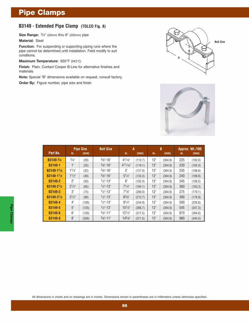
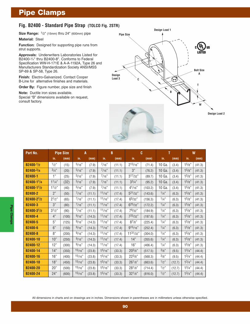
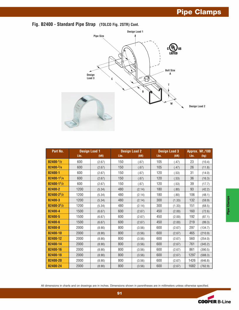
Size Range: 1/2" (15mm) thru 12" (300mm) pipe
Material: Steel
Function: Recommended for support of pipe lines running at adefinite distance from the wall or floor of a building or structure.
Maximum Temperature: — 650°F (343°C)
Finish: Plain. Contact Cooper B-Line for alterantive finishes andmaterials.
Note: Special “B” dimensions available on request,consult factory.
Order By: Figure number, pipe size and finish
Fig. B3148 - Offset Pipe Clamp (TOLCO Fig. 7)
Bolts and NutsIncluded
Bolt SizeB
CA
H2 Holes
Pipe Size A Bolt Size B C H Design Load Approx. Wt./100Part No. in. (mm) in. (mm) in. (mm) in. (mm) Lbs. (kN) Lbs. (kg)
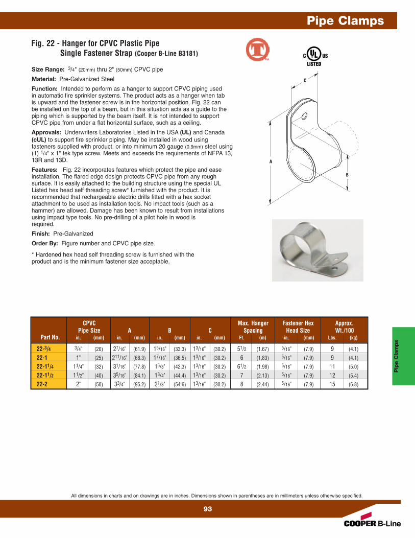
Function: Intended to perform as a hanger to support CPVC piping usedin automatic fire sprinkler systems. The product acts as a hanger when tabis upward and the fastener screw is in the horizontal position. Fig. 22 canbe installed on the top of a beam, but in this situation acts as a guide to thepiping which is supported by the beam itself. It is not intended to supportCPVC pipe from under a flat horizontal surface, such as a ceiling.
Approvals: Underwriters Laboratories Listed in the USA (UL) and Canada(cUL) to support fire sprinkler piping. May be installed in wood usingfasteners supplied with product, or into minimum 20 gauge (0.9mm) steel using(1) 1/4" x 1" tek type screw. Meets and exceeds the requirements of NFPA 13,13R and 13D.
Features: Fig. 22 incorporates features which protect the pipe and easeinstallation. The flared edge design protects CPVC pipe from any roughsurface. It is easily attached to the building structure using the special ULListed hex head self threading screw* furnished with the product. It isrecommended that rechargeable electric drills fitted with a hex socketattachment to be used as installation tools. No impact tools (such as ahammer) are allowed. Damage has been known to result from installationsusing impact type tools. No pre-drilling of a pilot hole in wood isrequired.
Finish: Pre-Galvanized
Order By: Figure number and CPVC pipe size.
* Hardened hex head self threading screw is furnished with theproduct and is the minimum fastener size acceptable.
C
A
B
CPVC Max. Hanger Fastener Hex Approx.Pipe Size A B C Spacing Head Size Wt./100
Part No. in. (mm) in. (mm) in. (mm) in. (mm) Ft. (m) in. (mm) Lbs. (kg)
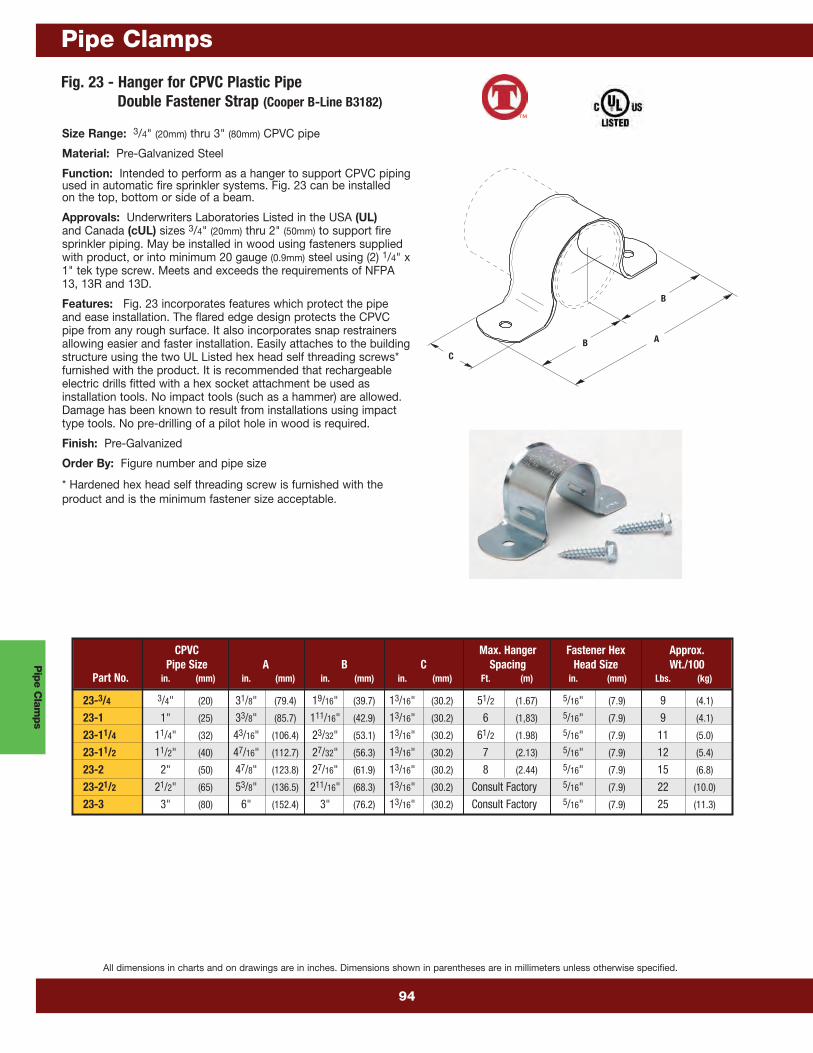
Function: Intended to perform as a hanger to support CPVC pipingused in automatic fire sprinkler systems. Fig. 23 can be installedon the top, bottom or side of a beam.
Approvals: Underwriters Laboratories Listed in the USA (UL)and Canada (cUL) sizes 3/4" (20mm) thru 2" (50mm) to support firesprinkler piping. May be installed in wood using fasteners suppliedwith product, or into minimum 20 gauge (0.9mm) steel using (2) 1/4" x1" tek type screw. Meets and exceeds the requirements of NFPA13, 13R and 13D.
Features: Fig. 23 incorporates features which protect the pipeand ease installation. The flared edge design protects the CPVCpipe from any rough surface. It also incorporates snap restrainersallowing easier and faster installation. Easily attaches to the buildingstructure using the two UL Listed hex head self threading screws*furnished with the product. It is recommended that rechargeableelectric drills fitted with a hex socket attachment be used asinstallation tools. No impact tools (such as a hammer) are allowed.Damage has been known to result from installations using impacttype tools. No pre-drilling of a pilot hole in wood is required.
Finish: Pre-Galvanized
Order By: Figure number and pipe size
* Hardened hex head self threading screw is furnished with theproduct and is the minimum fastener size acceptable.
A
CB
B
CPVC Max. Hanger Fastener Hex Approx.Pipe Size A B C Spacing Head Size Wt./100
Part No. in. (mm) in. (mm) in. (mm) in. (mm) Ft. (m) in. (mm) Lbs. (kg)
All dimensions in charts and on drawings are in inches. Dimensions shown in parentheses are in millimeters unless otherwise specified.
™
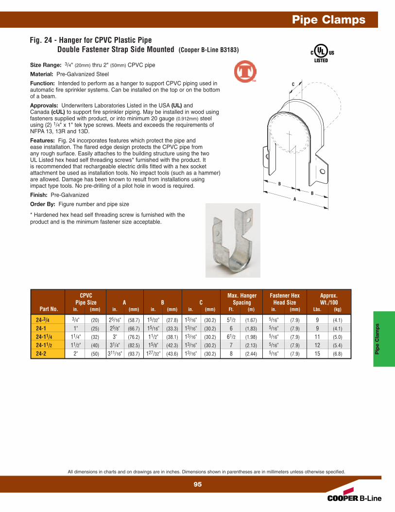
Fig. 24 - Hanger for CPVC Plastic PipeDouble Fastener Strap Side Mounted (Cooper B-Line B3183)
Size Range: 3/4" (20mm) thru 2" (50mm) CPVC pipe
Material: Pre-Galvanized Steel
Function: Intended to perform as a hanger to support CPVC piping used inautomatic fire sprinkler systems. Can be installed on the top or on the bottomof a beam.
Approvals: Underwriters Laboratories Listed in the USA (UL) andCanada (cUL) to support fire sprinkler piping. May be installed in wood usingfasteners supplied with product, or into minimum 20 gauge (0.912mm) steelusing (2) 1/4" x 1" tek type screws. Meets and exceeds the requirements ofNFPA 13, 13R and 13D.
Features: Fig. 24 incorporates features which protect the pipe andease installation. The flared edge design protects the CPVC pipe fromany rough surface. Easily attaches to the building structure using the twoUL Listed hex head self threading screws* furnished with the product. Itis recommended that rechargeable electric drills fitted with a hex socketattachment be used as installation tools. No impact tools (such as a hammer)are allowed. Damage has been known to result from installations usingimpact type tools. No pre-drilling of a pilot hole in wood is required.
Finish: Pre-Galvanized
Order By: Figure number and pipe size
* Hardened hex head self threading screw is furnished with theproduct and is the minimum fastener size acceptable.
C
A
B
B
CPVC Max. Hanger Fastener Hex Approx.Pipe Size A B C Spacing Head Size Wt./100
Part No. in. (mm) in. (mm) in. (mm) in. (mm) Ft. (m) in. (mm) Lbs. (kg)
Function: — Designed to be used in conjunction with Fig. 200 band hangersto restrict the upward movement of piping as it occurs during sprinkler headactivation or earthquake type activity. The surge restrainer is easily andefficiently installed by snapping into a locking position on the band hanger.This product is intended to satisfy the requirements as indicated in the NationalFire Protection Association NFPA 13, 2010 edition, 9.2.3.4.4.1 and 9.2.3.4.4.4Can be used to restrain either steel pipe or CPVC plastic Pipe.
Approvals: — Underwriters Laboratories Listed only when used with bandhanger Fig. 200, in the USA (UL) and Canada (cUL).
Finish: Pre-Galvanized
Order By: Figure number and band hanger, size from3/4" (20mm) thru 2" (40mm).
Patent #5,344,108
Pip
e Clam
ps
Pipe Clamps
96
All dimensions in charts and on drawings are in inches. Dimensions shown in parentheses are in millimeters unless otherwise specified.
™
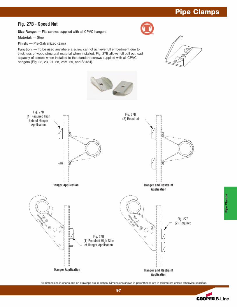
Fig. 27B - Speed NutSize Range: — Fits screws supplied with all CPVC hangers.
Material: — Steel
Finish: — Pre-Galvanized (Zinc)
Function: — To be used anywhere a screw cannot achieve full embedment due to thickness of wood structural material when installed. Fig. 27B allows full pull out loadcapacity of screws when installed to the standard screws supplied with all CPVChangers (Fig. 22, 23, 24, 28, 28M, 29, and B3184).
Hanger Application Hanger and RestraintApplication
Hanger and RestraintApplication
Fig. 27B(2) Required
Fig. 27B(2) Required
Fig. 27B(1) Required High
Side of HangerApplication
Fig. 27B(1) Required High Sideof Hanger Application
Hanger Application
Pip
e C
lam
ps
Pipe Clamps
All dimensions in charts and on drawings are in inches. Dimensions shown in parentheses are in millimeters unless otherwise specified.
97
™
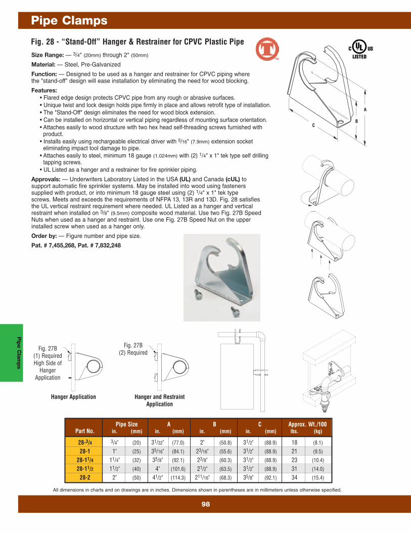
Fig. 28 - “Stand-Off” Hanger & Restrainer for CPVC Plastic PipeSize Range: — 3/4" (20mm) through 2" (50mm)
Material: — Steel, Pre-Galvanized
Function: — Designed to be used as a hanger and restrainer for CPVC piping wherethe "stand-off" design will ease installation by eliminating the need for wood blocking.
Features:• Flared edge design protects CPVC pipe from any rough or abrasive surfaces.• Unique twist and lock design holds pipe firmly in place and allows retrofit type of installation.• The "Stand-Off" design eliminates the need for wood block extension.• Can be installed on horizontal or vertical piping regardless of mounting surface orientation.• Attaches easily to wood structure with two hex head self-threading screws furnished with
product.• Installs easily using rechargeable electrical driver with 5/16" (7.9mm) extension socket
eliminating impact tool damage to pipe.• Attaches easily to steel, minimum 18 gauge (1.024mm) with (2) 1/4" x 1" tek type self drilling
tapping screws.• UL Listed as a hanger and a restrainer for fire sprinkler piping.
Approvals: — Underwriters Laboratory Listed in the USA (UL) and Canada (cUL) tosupport automatic fire sprinkler systems. May be installed into wood using fastenerssupplied with product, or into minimum 18 gauge steel using (2) 1/4" x 1" tek typescrews. Meets and exceeds the requirements of NFPA 13, 13R and 13D. Fig. 28 satisfiesthe UL vertical restraint requirement where needed. UL Listed as a hanger and verticalrestraint when installed on 3/8" (9.5mm) composite wood material. Use two Fig. 27B SpeedNuts when used as a hanger and restraint. Use one Fig. 27B Speed Nut on the upperinstalled screw when used as a hanger only.
Order by: — Figure number and pipe size.
Pat. # 7,455,268, Pat. # 7,832,248
C
A
B
Pipe Size A B C Approx. Wt./100Part No. in. (mm) in. (mm) in. (mm) in. (mm) lbs. (kg)
Hanger Application Hanger and RestraintApplication
Fig. 27B(2) Required
Fig. 27B(1) RequiredHigh Side of
HangerApplication
Pip
e Clam
ps
Pipe Clamps
98
All dimensions in charts and on drawings are in inches. Dimensions shown in parentheses are in millimeters unless otherwise specified.
™
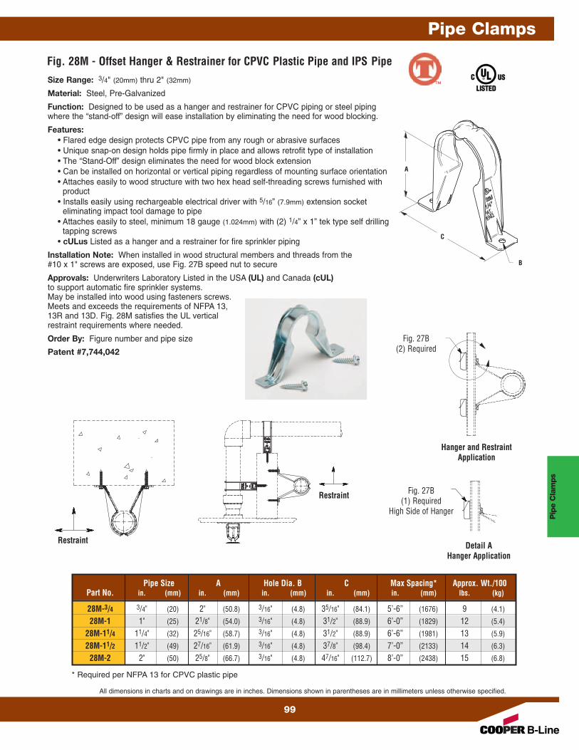
Fig. 28M - Offset Hanger & Restrainer for CPVC Plastic Pipe and IPS PipeSize Range: 3/4" (20mm) thru 2" (32mm)
Material: Steel, Pre-Galvanized
Function: Designed to be used as a hanger and restrainer for CPVC piping or steel pipingwhere the “stand-off” design will ease installation by eliminating the need for wood blocking.
Features:• Flared edge design protects CPVC pipe from any rough or abrasive surfaces• Unique snap-on design holds pipe firmly in place and allows retrofit type of installation• The “Stand-Off” design eliminates the need for wood block extension• Can be installed on horizontal or vertical piping regardless of mounting surface orientation• Attaches easily to wood structure with two hex head self-threading screws furnished with
product• Installs easily using rechargeable electrical driver with 5/16” (7.9mm) extension socket
eliminating impact tool damage to pipe• Attaches easily to steel, minimum 18 gauge (1.024mm) with (2) 1/4” x 1” tek type self drilling
tapping screws• cULus Listed as a hanger and a restrainer for fire sprinkler piping
Installation Note: When installed in wood structural members and threads from the#10 x 1" screws are exposed, use Fig. 27B speed nut to secure
Approvals: Underwriters Laboratory Listed in the USA (UL) and Canada (cUL)to support automatic fire sprinkler systems.May be installed into wood using fasteners screws.Meets and exceeds the requirements of NFPA 13,13R and 13D. Fig. 28M satisfies the UL verticalrestraint requirements where needed.
Order By: Figure number and pipe size
Patent #7,744,042
C
A
B
Pipe Size A Hole Dia. B C Max Spacing* Approx. Wt./100Part No. in. (mm) in. (mm) in. (mm) in. (mm) in. (mm) lbs. (kg)
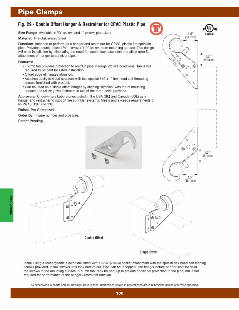
Size Range: Available in 3/4" (20mm) and 1" (25mm) pipe sizes
Material: Pre-Galvanized Steel
Function: Intended to perform as a hanger and restrainer for CPVC, plastic fire sprinklerpipe. Provides double offset 11/2” (20mm) x 11/2” (20mm) from mounting surface. This designwill ease installation by eliminating the need for wood block extension and allow retro-fitattachment of hanger to sprinkler pipe.
Features:• Thumb tab provides protection to restrain pipe in rough job site conditions. Tab is not
required to be bent for listed installation.• Offset edge eliminates abrasion.• Attaches easily to wood structure with two special #10 x 1” hex head self-threading
screws furnished with product.• Can be used as a single offset hanger by aligning "dimples" with top of mounting
surface and utilizing two fasteners in two of the three holes provided.
Approvals: Underwriters Laboratories Listed in the USA (UL) and Canada (cUL) as ahanger and restrainer to support fire sprinkler systems. Meets and exceeds requirements ofNFPA 13, 13R and 13D.
Finish: Pre-Galvanized
Order By: Figure number and pipe size.
Patent Pending
Install using a rechargeable electric drill fitted with a 5/16” (7.9mm) socket attachment with the special hex head self-tappingscrews provided. Install screws until they bottom out. Pipe can be “snapped” into hanger before or after installation ofthe screws to the mounting surface. “Thumb tab” may be bent up to provide additional protection to the pipe, but is notrequired for performance of the hanger / restrainer function.
Double Offset
Single Offset
1.5”(38.1mm)
1.5”(38.1mm)
1.5”(38.1mm)
1.5”(38.1mm)
Pip
e Clam
ps
Pipe Clamps
100
All dimensions in charts and on drawings are in inches. Dimensions shown in parentheses are in millimeters unless otherwise specified.
™
Fig. 3184 - Offset Hanger for CPVC Plastic Pipe and IPS PipeSize Range: 3/4" (20mm) thru 2" (32mm)
Material: Pre-Galvanized Steel
Function: Designed to be used as a hanger for CPVC piping or steel pipingwhere the “stand-off” design will ease installation by eliminating the need forwood blocking.
Features:• Flared edge design protects CPVC pipe from any rough or abrasive
surfaces• The “Stand-Off” design eliminates the need for wood block extension• Can be installed on horizontal or vertical piping regardless of mounting
surface orientation• Attaches easily to wood structure with two hex head self-threading
screws furnished with product• cULus Listed as a hanger for fire sprinkler piping
Installation Note: When installed in wood structural members and threadsfrom the #10 x 1" screws are exposed, use Fig. 27B speed nut to secure
Approvals: Underwriters Laboratory Listed in the USA (UL) and Canada(cUL) 3/4" (20mm) thru 2" (50mm) to support automatic fire sprinkler systems.May be installed into wood using fasteners screws. Meets and exceeds therequirements of NFPA 13, 13R and 13D.
Order By: Figure number and pipe size
Patent # 7,744,042
H
L
Pipe Size
CPVC L H Max. Hanger Fastener Hex Approx.Pipe Size Overall Overall Spacing Head Size Wt./100
Part No. in. (mm) in. (mm) in. (mm) ft. (m) in. (mm) Lbs. (kg)