33
FLOATING BALL VALVES
FLOATING BALL VALVES
© Cooper Cameron Corporation, Cooper Cameron Valves Division TC1822
Printed in Canada 08/04 NP-5M
FLOATING BALL VALVES
16500 South Main StreetMissouri City, Texas 77489281 499 8511USA Toll Free 800 323 9160www.ccvalve.com
C O O P E R C A M E R O NVALVES
USACOOPER CAMERON VALVESMissouri City, TexasPhone: 281-499-8511Fax: 281-261-3588
COOPER CAMERON VALVESOklahoma City, OklahomaPhone: 405-631-1321Fax: 405-629-0420
UKCOOPER CAMERON VALVESLivingston, ScotlandPhone: 44-1506-832-000Fax: 44-1506-432-948
CanadaCOOPER CAMERON CANADA CORPORATIONCalgary, AlbertaPhone: 403-398-9930Fax: 403-398-9936
COOPER CAMERON CANADA CORPORATIONEdmonton, AlbertaPhone: 780-435-0777Fax: 780-435-0700
MexicoCOOPER CAMERON de MEXICO S.A. de C.V.Mexico CityPhone: 52-555-580-0296Fax: 52-555-395-8669
Other Locations
Australia
Austria
Brazil
Brunei
Chile
Congo
Egypt
England
Gabon
Germany
Hungary
Indonesia
Ireland
Japan
Malaysia
Netherlands
New Zealand
Nigeria
Norway
Oman
Poland
Qatar
Russia
Saudi Arabia
UAE
Venezuela
ArgentinaCAMERON ARGENTINA S.A.I.C.Zarate, Pica Buenos AiresPhone: 54-11-4314-5520/5540Fax: 54-11-4311-2838
SingaporeCOOPER CAMERON (SINGAPORE) PTE. LTD.Phone: 65-6861-3355Fax: 65-6861-6197
FranceCAMERON FRANCE, S.A.Beziers, FrancePhone: 33-4-67-111-500Fax: 33-4-67-111-600
DYNASEAL 210DUCTILE IRON FLOATING BALL VALVES
How To Order 1
Features and Benefits 2 & 3
Detail View, Sizes, Standards and Specifications 4
Materials List 5
Dimensions and Weights 6
DYNASEAL 310FLOATING BALL VALVES
HOW TO ORDER
4 in. (100 mm) and Smaller 7 & 8
Features and Benefits 9 & 10
Exploded View 11 & 12
Trim Chart 13
DIMENSIONAL DATA
4 in. (100 mm) Full Port and Larger 14 & 15
Features and Benefits 16 & 17
Exploded View 18
Trim Chart 19
DIMENSIONAL DATA
All Sizes 20 & 21
PRESSURE/TEMPERATURE CHARTS 22 & 23
WEIGHTS 24 & 25
FLOW CHARACTERISTICS 25
STEM TORQUES 26 & 27
TERMS AND CONDITIONS 28 & 29
TRADEMARK INFORMATION 30
DYNASEAL FLOATING BALL VALVES
TABLE OF CONTENTS
TC182208/04 NP-5M
132 TC182208/04 NP-5M
TC182208/04 NP-5M
DYNASEAL 210 FLOATING BALL VALVES
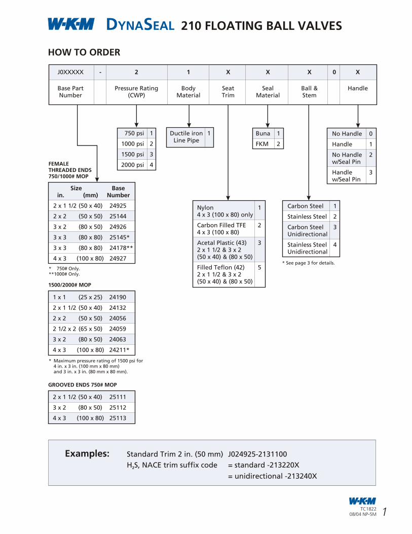
HOW TO ORDER
1 x 1 (25 x 25) 24190
2 x 1 1/2 (50 x 40) 24132
2 x 2 (50 x 50) 24056
2 1/2 x 2 (65 x 50) 24059
3 x 2 (80 x 50) 24063
4 x 3 (100 x 80) 24211*
750 psi 1
1000 psi 2
1500 psi 3
2000 psi 4
* Maximum pressure rating of 1500 psi for4 in. x 3 in. (100 mm x 80 mm)and 3 in. x 3 in. (80 mm x 80 mm).
No Handle 0
Handle 1
No Handle 2w/Seal Pin
Handle 3w/Seal Pin
J0XXXXX - 2 1 X X X 0 X
Base Part Pressure Rating Body Seat Seal Ball & HandleNumber (CWP) Material Trim Material Stem
Carbon Steel 1
Stainless Steel 2
Carbon Steel 3Unidirectional
Stainless Steel 4Unidirectional
Examples: Standard Trim 2 in. (50 mm) J024925-2131100
H S, NACE trim suffix code = standard -213220X2
= unidirectional -213240X
Ductile iron 1Line Pipe
Buna 1
FKM 2
Nylon 14 x 3 (100 x 80) only
Carbon Filled TFE 24 x 3 (100 x 80)
Acetal Plastic (43) 32 x 1 1/2 & 3 x 2(50 x 40) & (80 x 50)
Filled Teflon (42) 52 x 1 1/2 & 3 x 2(50 x 40) & (80 x 50)
Size Base in. (mm) Number
2 x 1 1/2 (50 x 40) 24925
2 x 2 (50 x 50) 25144
3 x 2 (80 x 50) 24926
3 x 3 (80 x 80) 25145*
3 x 3 (80 x 80) 24178**
4 x 3 (100 x 80) 24927
FEMALETHREADED ENDS750/1000# MOP
1500/2000# MOP
2 x 1 1/2 (50 x 40) 25111
3 x 2 (80 x 50) 25112
4 x 3 (100 x 80) 25113
GROOVED ENDS 750# MOP
* See page 3 for details.
NOTES
* 750# Only.**1000# Only.
2 31
NOTES
TC182208/04 NP-5M
TC182208/04 NP-5M
DYNASEAL 210 FLOATING BALL VALVES
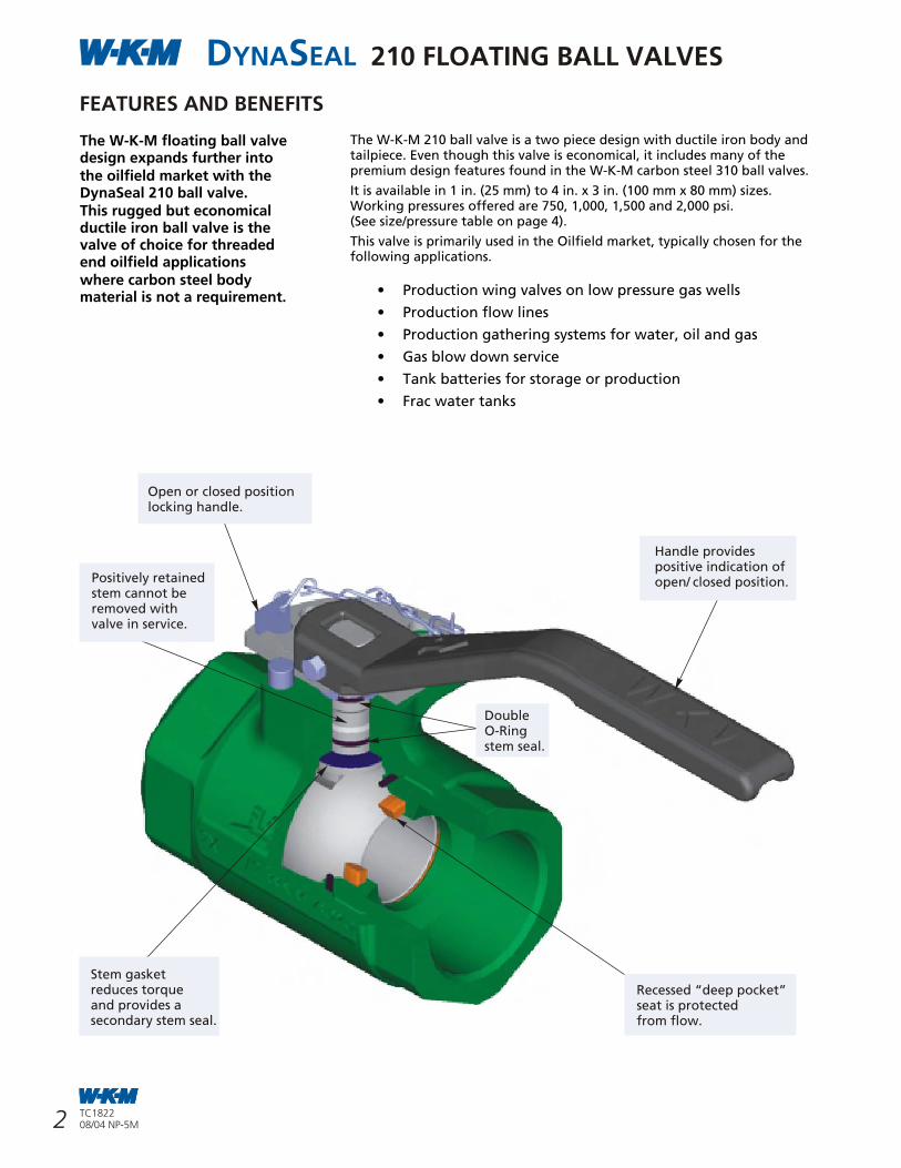
The W-K-M floating ball valve design expands further intothe oilfield market with the DynaSeal 210 ball valve.This rugged but economical ductile iron ball valve is the valve of choice for threaded end oilfield applicationswhere carbon steel body material is not a requirement.
Open or closed positionlocking handle.
Positively retainedstem cannot beremoved withvalve in service.
Handle providespositive indication ofopen/ closed position.
FEATURES AND BENEFITS
The W-K-M 210 ball valve is a two piece design with ductile iron body and tailpiece. Even though this valve is economical, it includes many of the premium design features found in the W-K-M carbon steel 310 ball valves.
It is available in 1 in. (25 mm) to 4 in. x 3 in. (100 mm x 80 mm) sizes. Working pressures offered are 750, 1,000, 1,500 and 2,000 psi.(See size/pressure table on page 4).
This valve is primarily used in the Oilfield market, typically chosen for the following applications.
• Production wing valves on low pressure gas wells
• Production flow lines
• Production gathering systems for water, oil and gas
• Gas blow down service
• Tank batteries for storage or production
• Frac water tanks
Recessed “deep pocket”seat is protectedfrom flow.
Stem gasketreduces torqueand provides asecondary stem seal.
DoubleO-Ringstem seal.
3
DYNASEAL FLOATING BALL VALVES
References in this catalog to registered trademarks or productdesignations, which are owned by Cooper Cameron Corporationare as follows:
®Cameron ®Demco
®DynaCentric®DynaSeal
®Foster®NAVCO
®Nutron®Orbit
®Pow-R-Seal®Saf-T-Seal
™Thornhill Craver®TruSeal™Unibolt
®W-K-M
References in this catalog to registered trademarks or productdesignations, which are not owned by Cooper CameronCorporation are as follows:
TRADE MARK INFORMATION
30 TC182208/04 NP-5M
TC182208/04 NP-5M
DYNASEAL 210 FLOATING BALL VALVES
UNIDIRECTIONAL BALL (OPTION)
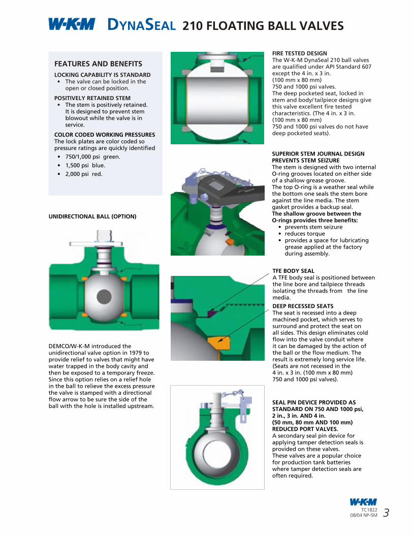
DEMCO/W-K-M introduced the unidirectional valve option in 1979 to provide relief to valves that might have water trapped in the body cavity and then be exposed to a temporary freeze. Since this option relies on a relief hole in the ball to relieve the excess pressure the valve is stamped with a directional flow arrow to be sure the side of the ball with the hole is installed upstream.
SUPERIOR STEM JOURNAL DESIGN PREVENTS STEM SEIZUREThe stem is designed with two internal O-ring grooves located on either side of a shallow grease groove.The top O-ring is a weather seal while the bottom one seals the stem boreagainst the line media. The stem gasket provides a backup seal.The shallow groove between the O-rings provides three benefits:
• prevents stem seizure• reduces torque• provides a space for lubricating
grease applied at the factory during assembly.
TFE BODY SEALA TFE body seal is positioned between the line bore and tailpiece threads isolating the threads from the line media.
DEEP RECESSED SEATS The seat is recessed into a deep machined pocket, which serves to surround and protect the seat on all sides. This design eliminates cold flow into the valve conduit where it can be damaged by the action of the ball or the flow medium. The result is extremely long service life.(Seats are not recessed in the4 in. x 3 in. (100 mm x 80 mm)750 and 1000 psi valves).
SEAL PIN DEVICE PROVIDED AS STANDARD ON 750 AND 1000 psi,2 in., 3 in. AND 4 in.(50 mm, 80 mm AND 100 mm) REDUCED PORT VALVES.A secondary seal pin device for applying tamper detection seals is provided on these valves.These valves are a popular choice for production tank batteries where tamper detection seals are often required.
FIRE TESTED DESIGNThe W-K-M DynaSeal 210 ball valves are qualified under API Standard 607except the 4 in. x 3 in.(100 mm x 80 mm)750 and 1000 psi valves.The deep pocketed seat, locked in stem and body/ tailpiece designs give this valve excellent fire tested characteristics. (The 4 in. x 3 in. (100 mm x 80 mm)750 and 1000 psi valves do not havedeep pocketed seats).
FEATURES AND BENEFITS
LOCKING CAPABILITY IS STANDARD• The valve can be locked in the
open or closed position.
POSITIVELY RETAINED STEM• The stem is positively retained.
It is designed to prevent stem blowout while the valve is in service.
COLOR CODED WORKING PRESSURESThe lock plates are color coded so pressure ratings are quickly identified
• 750/1,000 psi green.
• 1,500 psi blue.
• 2,000 psi red.
Trademark Owner Common Name Comparable CCV Abbreviated Name (in Trim Charts)
Aflas Asahi Glass Company TFE Propylene FXM
Celcon Hoechst Celanese Corporation
Delrin E.I. DuPont De Nemours & Company
PEEK Victrex PLC Corp United Kingdom Polyetheretherketone PK
Stellite Stoody Deloro Stellite, Inc.
Teflon E.I. DuPont De Nemours & Company Poly Tetra Fluoro Ethylene PTFE
Viton DuPont Dow Elastomers L.L.C. Fluoroelastomer FKM
17-4PH Armco Advanced Materials Corp. 17-4PH Stainless Steel Type 630
Electroless Nickel Plating ENP
4
for any delays, loss of use or for other direct,
indirect, incidental or consequential damages
incurred by reason of any such judgment. Seller
does not warrant that such material or
apparatus (a) will not infringe any such patent
when not manufactured by or for Seller or when
specially made in whole or in part to the Buyer's
design specification and such infringement arises
from the inclusion of such specified design or (b),
if used or sold in combination with other
material or apparatus, or if used in the practice
of a process, will not, as a result of such
combination or use, infringe any patent covering
such combination or process; and Seller shall not
be liable for and does not indemnify Buyer for
damages or losses of any nature whatsoever
resulting from actual or alleged patent
infringement arising pursuant to (a) or (b)
above.
11. SELLER'S RIGHT TO MANUFACTURE: Seller in its sole discretion shall have the right
to manufacture the products provided
hereunder as far in advance of its estimated
shipping schedule as it deems appropriate. Seller
expressly reserves the right to change or modify
the design and construction of any product in
due course of Seller's manufacturing procedure
without incurring any obligation or liability to
furnish or install such changes, modifications or
improvements to products previously or
subsequently sold.
12. ENGINEERING AND SERVICE: Upon request, Seller will provide engineering
and/or technical information regarding its
products and their uses and if feasible, will
provide personnel to assist Buyer in effecting
field installations and/or field service. Any such
information, service or assistance so provided,
whether with or without charge, shall be
advisory only. In that regard, neither Seller nor
Buyer assumes any liability for the acts or
omissions of the other party except as may be
provided in these terms.
13. LABOR STANDARDS: Seller hereby certifies that these products were
produced in accordance with all applicable
requirements of Section 6, 7 and 12 of the
Fair Labor Standards Act as amended and of
regulations and orders of the United States
Department of Labor issued under Section 14
thereof.
14. INSPECTION: Unless otherwise agreed in writing, final
inspection and acceptance of products must be
made at Seller's plant or other shipping or
receiving point designated by Seller and shall
be conclusive except as regards latent defects.
Buyer's representatives may inspect at the
Seller's plant or shipping point during working
hours prior to shipment in such manner as will
not interfere with operations.
15. DELIVERY AND ACCEPTANCE: Delivery shall be in accordance with the
requirements in the Purchase Contract, provided,
in the event Buyer is unable to accept delivery
upon completion of the manufacture of the
Goods in accordance with such requirements,
Buyer agrees that (i) title and risk of ownership
shall pass to Buyer on date of Seller's invoice and
(ii) Buyer will make payments within thirty days
after date of such invoice. Seller shall retain
custodial risk of loss until delivery is made in
accordance with such requirements.
16. TRANSPORTATION CHARGES, ALLOWANCES, CLAIMS:
All prices are F.O.B. Seller's plant or other
designated shipping point.
No freight is allowed unless stated in Seller's
quotation (if any) or in a written contract which
may exist between Seller and Buyer at the time
of shipment. If Seller's quotation or a written
contract states that all or a portion of freight is
allowed, all prices are F.O.B. Seller's plant or
other designated shipping point, with most
economical surface transportation allowed. If
the quoted or contractual price includes
transportation, Seller reserves the right to
designate the common carrier and to ship in the
manner it deems most economical. Added costs
due to special routing requested by the Buyer
are chargeable to the Buyer. Under no
circumstances is any freight allowance which is
absorbed by Seller to be deducted from the
selling price. If the quoted price or contract
includes transportation, no deduction will be
made in lieu thereof whether Buyer accepts
shipment at plant, warehouse, freight station,
or otherwise supplies its own transportation.
When sales are made from the Seller's
warehouse, Seller reserves the right to charge
either actual or pro-rated freight from Seller's
principle point of manufacture to Seller's
warehouse. Buyer assumes risk of loss upon
delivery to the carrier, regardless of who pays
shipping costs.
Seller endeavors to pack or prepare all
shipments so that they will not break, rust or
deteriorate in transit, but does not guarantee
against such damage. Unless requested in
writing by the Buyer, no shipments are insured
by Seller against damage or loss in transit. Seller
will place insurance as nearly as possible in
accordance with Buyer's written instructions but
in such case Seller acts only as agent between
the insurance company and the Buyer and
assumes no liability whatsoever.
Any claims for shipping loss, breakage or
damage (obvious or concealed) are Buyer's
responsibility and should be made to the carrier.
All claims regarding shortages must be made
within thirty (30) days from receipt of shipment
and must be accompanied by the packing list(s)
covering the shipment.
17. CONSULAR INVOICES: Consular fees for legalizing invoices, stamping
bills of lading, or other documents required
by the laws of any country or destination are
not included in quotations or selling prices.
If instructed in writing, Seller will make
arrangements for consular documents and
declarations as agent of the Buyer, but Seller
assumes no liability whatsoever as a result of
making such arrangements. Seller assumes no
responsibility for any fines or other charges
imposed due to errors or incorrect declarations.
CAM/T&C/US/96 REV. 9/03
18. INDEMNIFICATION AND LIMITATION OF LIABILITY: A. INDEMNIFICATION:
Seller agrees to indemnify Buyer and hold Buyer
harmless against any claims, demands or causes
of action for property damage or personal injury
(including death) caused by the negligent act or
omission of any employee, agent or sub-
contractor of Seller and not contributed to by
the negligence of Buyer, its employees, its agents
or any third party. Seller shall not be responsible
for the acts and workmanship of employees,
agents, contractors or subcontractors of Buyer
or any third party, nor for failure or malfunction
of any tools, materials, equipment, products,
supplies, facilities or devices not manufactured
and supplied by Seller. Buyer agrees to hold
Seller harmless from any and all losses, claims,
or damages arising from subsurface damage,
surface damage caused by subsurface damage,
loss of hydrocarbons and from pollution,
regardless of whether such damages, losses or
claims were caused by the negligence or sole
negligence of Seller, it being the intent of the
parties that this indemnity shall apply to
property of Buyer or to that of any third party.
B. LIMITATION OF LIABILITY:
UNDER NO CIRCUMSTANCES SHALL SELLER BE
LIABLE FOR ANY SPECIAL, CONSEQUENTIAL OR
INCIDENTAL DAMAGES, INCLUDING, BUT NOT
LIMITED TO LOSS OF ANTICIPATED PROFITS,
LOSS OF USE OF EQUIPMENT OR OF ANY
INSTALLATION, SYSTEM OR FACILITY INTO
WHICH SELLER'S EQUIPMENT MAY BE LOCATED
OR AT WHICH SELLER, ITS AGENT OR
SUBCONTRACTOR MAY BE PERFORMING WORK.
Seller's total responsibility for any claims,
damages, losses or liabilities arising out of or
related to its performance of this contract or
the products or services covered hereunder shall
not exceed the purchase price.
19. MODIFICATION, RESCISSION & WAIVER: The terms herein may not be modified or
rescinded nor any of its provisions waived unless
such modification, rescission or waiver is in
writing and signed by an authorized employee
of Seller at its office in Houston, Texas.
Failure of Seller to insist in anyone or more
instances upon the performance of any of the
terms and conditions of the contract or the
failure of Seller to exercise any of its rights
hereunder shall not be construed as a waiver
or relinquishment of any such term, condition,
or right hereunder and shall not affect Seller's
right to insist upon strict performance and
compliance with regard to any unexecuted
portions of this contract or future performance
of these terms and conditions.
All orders must be accepted by an authorized
employee of Seller. The rights and duties of the
parties and construction and effect of all
provisions hereof shall be governed by and
construed according to the internal laws of the
State of Texas. Any disputes which arise under
this agreement shall be venued in the District
Court of Harris County, Texas or in the Southern
District of Texas.
29TC182208/04 NP-5M
TC182208/04 NP-5M
DYNASEAL 210 FLOATING BALL VALVES
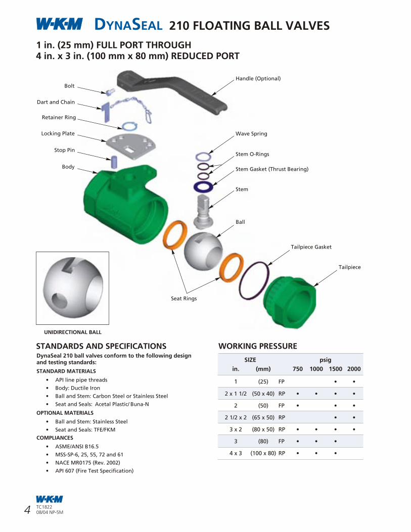
1 in. (25 mm) FULL PORT THROUGH4 in. x 3 in. (100 mm x 80 mm) REDUCED PORT
DynaSeal 210 ball valves conform to the following design and testing standards:
STANDARD MATERIALS
• API line pipe threads
• Body: Ductile Iron
• Ball and Stem: Carbon Steel or Stainless Steel
• Seat and Seals: Acetal Plastic/ Buna-N
OPTIONAL MATERIALS
• Ball and Stem: Stainless Steel
• Seat and Seals: TFE/FKM
COMPLIANCES
• ASME/ANSI B16.5
• MSS-SP-6, 25, 55, 72 and 61
• NACE MR0175 (Rev. 2002)
• API 607 (Fire Test Specification)
STANDARDS AND SPECIFICATIONS
SIZE psig
in. (mm) 750 1000 1500 2000
1 (25) FP • •
2 x 1 1/2 (50 x 40) RP • • • •
2 (50) FP • • •
2 1/2 x 2 (65 x 50) RP • •
3 x 2 (80 x 50) RP • • • •
3 (80) FP • • •
4 x 3 (100 x 80) RP • • •
WORKING PRESSURE
Ball
Stem Gasket (Thrust Bearing)
Stem
Stem O-Rings
Tailpiece Gasket
Seat Rings
Tailpiece
Locking Plate
Stop Pin
Retainer Ring
Handle (Optional)
Wave Spring
Dart and Chain
Bolt
Body
UNIDIRECTIONAL BALL
5
DYNASEAL 310 FLOATING BALL VALVESTERMS AND CONDITIONS1. CONTRACT ACCEPTANCE: Any written or oral purchase order received
from Buyer by Cooper Cameron Corporation,
Cameron Division and Cooper Cameron Valves
("Seller”) shall be construed as a written
acceptance of Seller's offer to sell and shall be
filled in accordance with the terms and conditions
of sale set forth herein. SELLER'S ACCEPTANCE OF
THIS ORDER IS EXPRESSLY CONDITIONED ON
BUYER'S ASSENT TO THE TERMS CONTAINED
HEREIN. The terms and conditions of Seller's
proposal (if any) and acknowledgement shall
prevail over any conflicting or different terms in
Buyer's order unless Buyer notifies Seller in writing
of its objections thereto within fifteen (15) days
from receipt of Seller's acknowledgement. Buyer's
standard terms of purchase will not be considered
a counteroffer to Seller's terms and conditions of
sale. The failure of Seller to object to any provision
in conflict herewith whether contained on Buyer's
purchase order or otherwise shall not be
construed as a waiver of the provisions hereof
nor as an acceptance thereof.
2. QUOTATIONS AND PRICES: All quotations are made for prompt acceptance
and any terms quoted therein are subject to
change without notice after thirty (30) days from
the date quoted unless specifically stated
otherwise on the quotation. Any product, service
capability or manufacturing capability which may
be available at the time a quotation is made is
subject to prior sale. Prices quoted are valid for
thirty (30) days unless specifically stated otherwise
on the quotation and are subject to change
without notice. The price in effect at the time of
shipment including any escalation formula will
apply, unless a valid quotation or written
agreement to the contrary exists between Buyer
and Seller. All prices shown are in U.S. dollars
and are F.O.B. Seller‘s shipping point.
Any documentation pertaining to traceability
requirements for raw materials or products or
documentation required for any routine or
special processes must be identified by the Buyer
at the time of quotation (if any) or at the time of
order placement.
3. TAXES: Any tax or other charge imposed by law on the
sale or production of goods or the performance
of services shall be paid by the Buyer, unless the
law specifically provides that such payment must
be made by Seller, in which case Buyer shall
reimburse Seller for such payment as part of the
purchase price. Custom duties, consular fees,
insurance charges and other comparable charges
will be borne by Buyer.
4. SHIPPING SCHEDULE AND DELIVERY: Shipment schedules are given as accurately as
conditions permit and every effort will be made
to make shipments as scheduled. Seller will not
be responsible for deviations in meeting shipping
schedules nor for any losses or damages to Buyer
(or any third party) occasioned by deviations in
the shipping schedule, whether due to Acts of
God, orders bearing priority ratings established
pursuant to law, differences with workmen, local
labor shortages, fire, flood, shortages or failure
of raw materials, supplies, fuel, power or
transportation, breakdown of equipment or any
other causes beyond Seller's reasonable control,
whether of similar or dissimilar nature than those
enumerated. Seller shall have additional time
within which to perform as may be reasonably
necessary under the circumstances and shall have
the right to apportion its production among its
customers in such a manner as it may consider to
be equitable.
Seller reserves the right to furnish commercially
equivalent or better substitutes for materials or
to subcontract the Buyer's order or portions
thereof as Seller deems necessary. In no event
shall Seller be liable for any consequential
damages for labor resulting from failure or
delay in shipment. If Buyer requires drawings,
procedures, standards or similar material for
approval, shipping schedules will be calculated
from the time such approvals are received by
Seller, since shipping schedules are based on
Seller having all required information and a
firm order from Buyer which is enterable into
production. Any hold points, witness points or
the need for inspection by Buyer's represent-
atives must be identified by Buyer at the time
of quotation (if any) and/or order placement in
order that the effect on the prices or shipping
schedules (if any) can be taken into account.
Additional inspection or testing required by
Buyer which affects normal production
sequence will be considered as extending
the shipping dates accordingly.
5. MINIMUM BILLING: Seller reserves the right to impose a minimum
billing charge on all sales, change orders or
order supplements.
6. TERMS OF PAYMENT: Terms of payment for all materials and service
are 30 days from invoice date, at net price,
provided satisfactory credit has been established.
All unpaid invoices are subject to the maximum
legal interest rate per annum commencing with
the due date.
7. CANCELLATIONS AND RETURNS: Purchase orders once placed by Buyer and
accepted by Seller can be canceled only with
Seller's written consent and upon terms which
will save Seller from loss. No products may be
returned for credit or adjustment without
written permission from Seller's office
authorized to issue such permission.
8. WARRANTIES: All products of Seller's manufacture are
warranted against defects of material and
workmanship for a period of twelve (12)
months from the date of installation or
eighteen (18) months from date of shipment,
whichever period first expires, when such
products are used in the service and within
the pressure range for which they were
manufactured. In the case of products or parts
not wholly of Seller's manufacture, Seller's
liability shall be limited to the extent of its
recovery from the manufacturer of such
products or parts under its liability to Seller.
Any repair work performed by Seller is warranted
for one year from completion of such repairs and
applies only to work performed.
If, within these specified periods, Seller receives
notice from Buyer of any alleged defect in or
nonconformance of any product or repair and if,
in the Seller's sole judgment, the product or repair
does not conform or is found to be defective in
material or workmanship, then, Buyer shall, at
Seller's request, return the part or product F.O.B.
to Seller's designated plant or service location.
Seller has no liability for removal or reinstallation
of products or equipment from below the surface
of the water. Seller, at its option and expense,
shall repair or replace the defective part or product,
or repay to Buyer the full price paid by Buyer for
such defective part, repair or product. Any
repayment of purchase price shall be without
interest.
Seller's warranty liability, including defects
caused by Seller's negligence, shall be limited to
such repair, replacement or refund, and shall not
include claims for labor costs, expenses of Buyer
resulting from such defects, recovery under general
tort law or strict liability or for damages resulting
from delays, loss of use, or other direct, indirect,
incidental or consequential damages of any kind.
Seller will not be responsible for failures of products
which have been in any way tampered with or
altered by anyone other than an authorized
representative of Seller, failures due to lack of
compliance with recommended maintenance
procedures or products which have been repaired
or altered in such a way (in Seller's judgment) as to
affect the products adversely. THIS WARRANTY IS
EXPRESSLY IN LIEU OF ALL OTHER WARRANTIES,
EXPRESS, STATUTORY OR IMPLIED, INCLUDING THE
WARRANTY OF MERCHANTABILITY AND FITNESS
FOR PARTICULAR PURPOSE WHICH EXCEED
THE FOREGOING WARRANTY.
9. NUCLEAR SALES: The products sold hereunder are not designed or
manufactured for use in or with any atomic
installation or activity. If the Buyer or ultimate
user of these products intends to use them in such
an installation or activity, Seller's Nuclear Terms of
Sale shall be part of and control this contract.
Seller will furnish Buyer with a copy of its Nuclear
Terms of Sale upon request.
10. PATENT INFRINGEMENT: Seller warrants that the use or sale of material
or apparatus sold or rented by it to Buyer
hereunder will not infringe United States' patents
of others covering such material or apparatus by
itself, and hereby agrees to indemnify Buyer against
judgment for damages for such infringement of
any such patent, provided that Buyer shall, upon
receipt of any claim for infringement of any such
patent or threat of suit for such infringement or
upon the filing of any suit for infringement, which-
ever comes first, promptly notify Seller in writing
and afford Seller full opportunity, at its option and
its own expense, to answer such claim or threat
of suit, assume the control of the defense of said
suit, and settle or compromise same in any way
Seller sees fit. Other than court-awarded
judgments as aforesaid Seller shall not be liable
28 TC182208/04 NP-5M
TC182208/04 NP-5M
DYNASEAL 210 FLOATING BALL VALVES
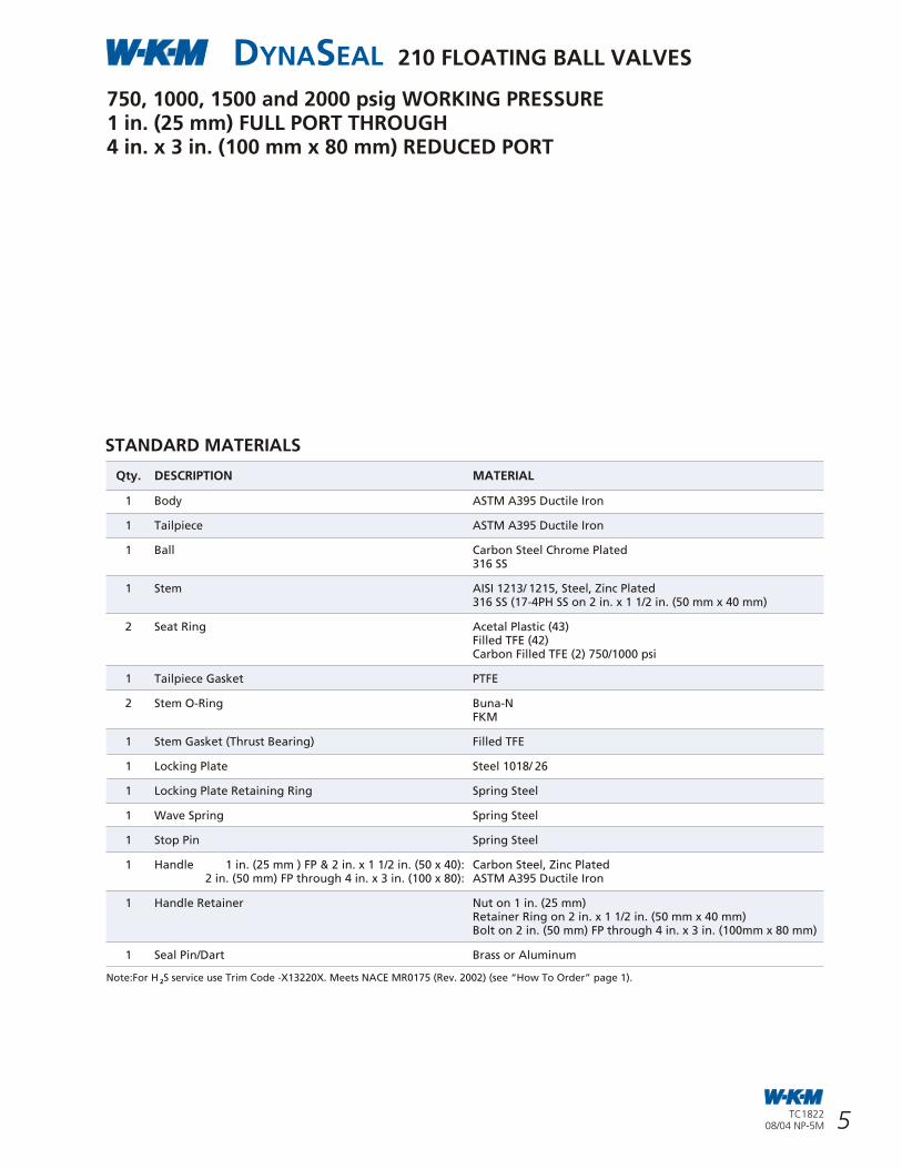
750, 1000, 1500 and 2000 psig WORKING PRESSURE1 in. (25 mm) FULL PORT THROUGH4 in. x 3 in. (100 mm x 80 mm) REDUCED PORT
STANDARD MATERIALS
Qty. DESCRIPTION MATERIAL
1 Body ASTM A395 Ductile Iron
1 Tailpiece ASTM A395 Ductile Iron
1 Ball Carbon Steel Chrome Plated316 SS
1 Stem AISI 1213/ 1215, Steel, Zinc Plated 316 SS (17-4PH SS on 2 in. x 1 1/2 in. (50 mm x 40 mm)
2 Seat Ring Acetal Plastic (43)Filled TFE (42)Carbon Filled TFE (2) 750/1000 psi
1 Tailpiece Gasket PTFE
2 Stem O-Ring Buna-NFKM
1 Stem Gasket (Thrust Bearing) Filled TFE
1 Locking Plate Steel 1018/ 26
1 Locking Plate Retaining Ring Spring Steel
1 Wave Spring Spring Steel
1 Stop Pin Spring Steel
1 Handle 1 in. (25 mm ) FP & 2 in. x 1 1/2 in. (50 x 40): Carbon Steel, Zinc Plated 2 in. (50 mm) FP through 4 in. x 3 in. (100 x 80): ASTM A395 Ductile Iron
1 Handle Retainer Nut on 1 in. (25 mm)Retainer Ring on 2 in. x 1 1/2 in. (50 mm x 40 mm)Bolt on 2 in. (50 mm) FP through 4 in. x 3 in. (100mm x 80 mm)
1 Seal Pin/Dart Brass or Aluminum
Note:For H S service use Trim Code -X13220X. Meets NACE MR0175 (Rev. 2002) (see “How To Order” page 1).2
6 27
DYNASEAL 310 FLOATING BALL VALVES
TC182208/04 NP-5M
TC182208/04 NP-5M
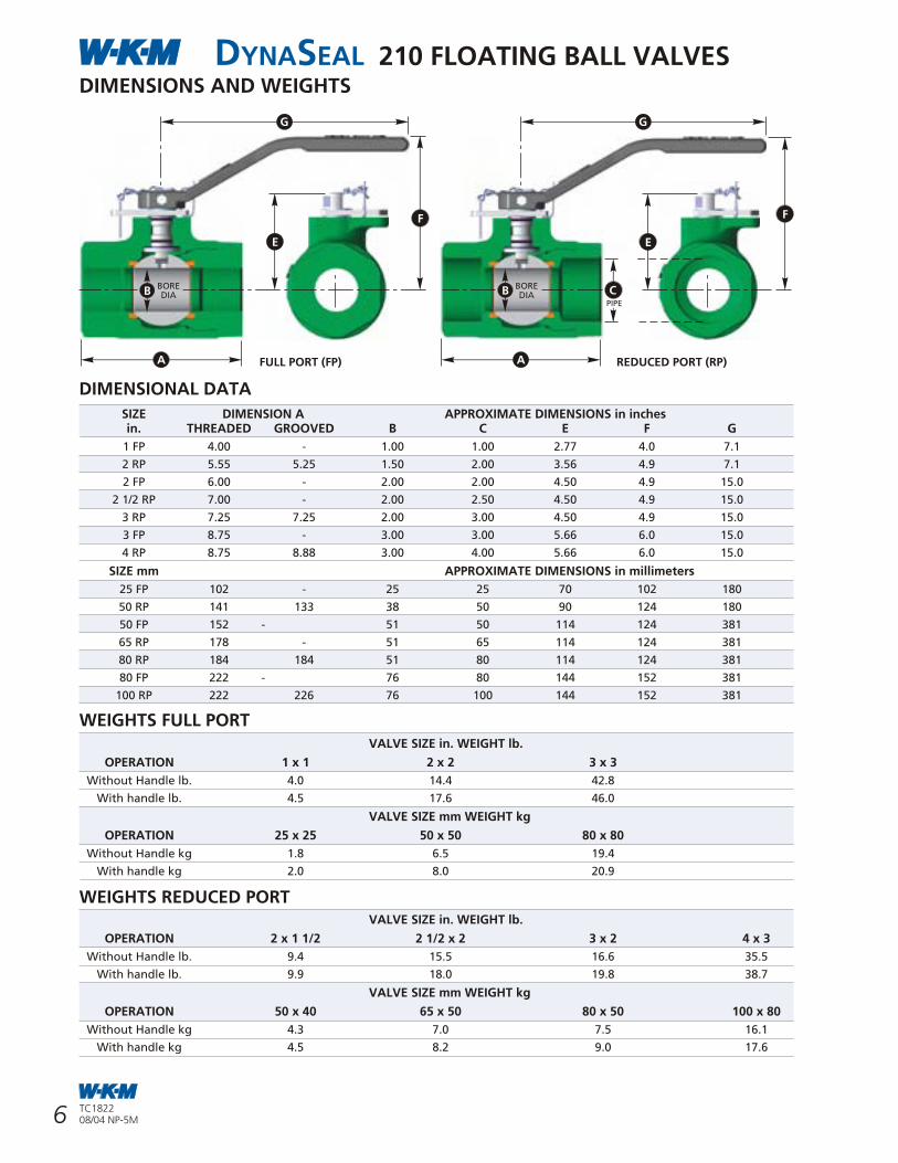
DYNASEAL 210 FLOATING BALL VALVESDIMENSIONS AND WEIGHTS
FULL PORT (FP) REDUCED PORT (RP)
DIMENSIONAL DATA
SIZE DIMENSION A APPROXIMATE DIMENSIONS in inchesin. THREADED GROOVED B C E F G
1 FP 4.00 - 1.00 1.00 2.77 4.0 7.1
2 RP 5.55 5.25 1.50 2.00 3.56 4.9 7.1
2 FP 6.00 - 2.00 2.00 4.50 4.9 15.0
2 1/2 RP 7.00 - 2.00 2.50 4.50 4.9 15.0
3 RP 7.25 7.25 2.00 3.00 4.50 4.9 15.0
3 FP 8.75 - 3.00 3.00 5.66 6.0 15.0
4 RP 8.75 8.88 3.00 4.00 5.66 6.0 15.0
SIZE mm APPROXIMATE DIMENSIONS in millimeters
25 FP 102 - 25 25 70 102 180
50 RP 141 133 38 50 90 124 180
50 FP 152 - 51 50 114 124 381
65 RP 178 - 51 65 114 124 381
80 RP 184 184 51 80 114 124 381
80 FP 222 - 76 80 144 152 381
100 RP 222 226 76 100 144 152 381
WEIGHTS FULL PORT
WEIGHTS REDUCED PORTVALVE SIZE in. WEIGHT lb.
OPERATION 2 x 1 1/2 2 1/2 x 2 3 x 2 4 x 3
Without Handle lb. 9.4 15.5 16.6 35.5
With handle lb. 9.9 18.0 19.8 38.7
VALVE SIZE mm WEIGHT kg
OPERATION 50 x 40 65 x 50 80 x 50 100 x 80
Without Handle kg 4.3 7.0 7.5 16.1
With handle kg 4.5 8.2 9.0 17.6
VALVE SIZE in. WEIGHT lb.
OPERATION 1 x 1 2 x 2 3 x 3
Without Handle lb. 4.0 14.4 42.8
With handle lb. 4.5 17.6 46.0
VALVE SIZE mm WEIGHT kg
OPERATION 25 x 25 50 x 50 80 x 80
Without Handle kg 1.8 6.5 19.4
With handle kg 2.0 8.0 20.9
PIPE
A
E
B BOREDIAB
BOREDIA
F
C
A
G G
STEM TORQUES (in. lb.)
SEAT SEAL CODE 23
VALVE BORE SIZE DIFFERENTIAL PRESSURE
in. (mm) 0-275 500 740 1000 1500 2000 2250 2500 3000 3500 3750 4000 4500 5000
1/4 - 3/8 (8 - 10) 60 60 60 60 60 65 70 85 100 115 125 130 150 165
1/2 (15) 70 70 70 82 110 125 140 180 220 276 310 - - -
3/4 (20) 108 108 125 140 190 260 340 420 560 695 800 - - -
Note: The torque values listed for 275 psi and greater are based on valves controlling the flow of clean lubricating liquid at ambient temperature.
For valves at pressure less that 275 psi use the value for 275 psi.
Interpolation may be used for any pressure above 275 psi but less than maximum pressure listed.
Running torque values will average two-thirds of these values.
For running torque values less than breakaway torque values at 275 psi use breakawaytorque values.
Reseating torque is equal to breakaway torque.
For operating temperatures between -20°F to -50°F (-29°C to -46°C) multiply these values by 1.20.
These torque values do not contain service or safety factors.
Actuator selection should be made based on experience and appropriate service andsafety factors.
SEAT SEAL CODE 01
VALVE BORE SIZE DIFFERENTIAL PRESSURE (psi)
in. (mm) 0-275 500 740
4 (100) 2090 3300 4200
6 (150) 4400 8200 11200
8 (200) 9000 14000 20300
10 (250) 15000 22000 30500
12 (300) 29300 37400 46400
** Multiply Trim 42 Torque x 2 for Seat Seal Codes 60, 60A, 92H.
SEAT SEAL CODES 28, 42**
VALVE BORE SIZE DIFFERENTIAL PRESSURE (psi)
in. (mm) 0-275 500 740
4 (100) 2400 3300 4200
6 (150) 5400 8200 11200
8 (200) 10000 15000 20300
10 (250) 16000 23000 30500
12 (300) 32000 39000 46500
F
E
7
DYNASEAL 310 FLOATING BALL VALVES
26 TC182208/04 NP-5M
TC182208/04 NP-5M
DYNASEAL 310 FLOATING BALL VALVES
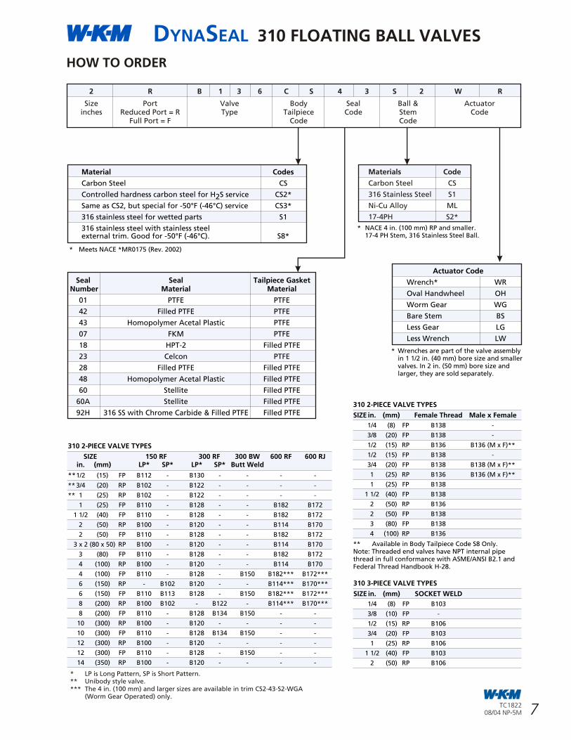
HOW TO ORDER
Seal Seal Tailpiece Gasket Number Material Material
01 PTFE PTFE
42 Filled PTFE PTFE
43 Homopolymer Acetal Plastic PTFE
07 FKM PTFE
18 HPT-2 Filled PTFE
23 Celcon PTFE
28 Filled PTFE Filled PTFE
48 Homopolymer Acetal Plastic Filled PTFE
60 Stellite Filled PTFE
60A Stellite Filled PTFE
92H 316 SS with Chrome Carbide & Filled PTFE Filled PTFE
2 R B 1 3 6 C S 4 3 S 2 W R
Size Port Valve Body Seal Ball & Actuatorinches Reduced Port = R Type Tailpiece Code Stem Code
Full Port = F Code Code
Materials Code
Carbon Steel CS
316 Stainless Steel S1
Ni-Cu Alloy ML
17-4PH S2*
Material Codes
Carbon Steel CS
Controlled hardness carbon steel for H S service CS2*2Same as CS2, but special for -50°F (-46°C) service CS3*
316 stainless steel for wetted parts S1
316 stainless steel with stainless steelexternal trim. Good for -50°F (-46°C). S8*
* Meets NACE *MR0175 (Rev. 2002)
* NACE 4 in. (100 mm) RP and smaller. 17-4 PH Stem, 316 Stainless Steel Ball.
Actuator Code
Wrench* WR
Oval Handwheel OH
Worm Gear WG
Bare Stem BS
Less Gear LG
Less Wrench LW
* Wrenches are part of the valve assemblyin 1 1/2 in. (40 mm) bore size and smaller valves. In 2 in. (50 mm) bore size andlarger, they are sold separately.
310 2-PIECE VALVE TYPES
SIZE 150 RF 300 RF 300 BW 600 RF 600 RJin. (mm) LP* SP* LP* SP* Butt Weld
**1/2 (15) FP B112 - B130 - - - -
** 3/4 (20) RP B102 - B122 - - - -
** 1 (25) RP B102 - B122 - - - -
1 (25) FP B110 - B128 - - B182 B172
1 1/2 (40) FP B110 - B128 - - B182 B172
2 (50) RP B100 - B120 - - B114 B170
2 (50) FP B110 - B128 - - B182 B172
3 x 2 (80 x 50) RP B100 - B120 - - B114 B170
3 (80) FP B110 - B128 - - B182 B172
4 (100) RP B100 - B120 - - B114 B170
4 (100) FP B110 - B128 - B150 B182*** B172***
6 (150) RP - B102 B120 - - B114*** B170***
6 (150) FP B110 B113 B128 - B150 B182*** B172***
8 (200) RP B100 B102 - B122 - B114*** B170***
8 (200) FP B110 - B128 B134 B150 - -
10 (300) RP B100 - B120 - - - -
10 (300) FP B110 - B128 B134 B150 - -
12 (300) RP B100 - B120 - - - -
12 (300) FP B110 - B128 - B150 - -
14 (350) RP B100 - B120 - - - -
310 2-PIECE VALVE TYPES
SIZE in. (mm) Female Thread Male x Female
1/4 (8) FP B138 -
3/8 (20) FP B138 -
1/2 (15) RP B136 B136 (M x F)**
1/2 (15) FP B138 -
3/4 (20) FP B138 B138 (M x F)**
1 (25) RP B136 B136 (M x F)**
1 (25) FP B138
1 1/2 (40) FP B138
2 (50) RP B136
2 (50) FP B138
3 (80) FP B138
4 (100) RP B136
** Available in Body Tailpiece Code S8 Only.Note: Threaded end valves have NPT internal pipe thread in full conformance with ASME/ANSI B2.1 andFederal Thread Handbook H-28.
* LP is Long Pattern, SP is Short Pattern.** Unibody style valve.*** The 4 in. (100 mm) and larger sizes are available in trim CS2-43-S2-WGA
(Worm Gear Operated) only.
310 3-PIECE VALVE TYPES
SIZE in. (mm) SOCKET WELD
1/4 (8) FP B103
3/8 (10) FP -
1/2 (15) RP B106
3/4 (20) FP B103
1 (25) RP B106
1 1/2 (40) FP B103
2 (50) RP B106
STEM TORQUES (in. lb.)
SEAT SEAL CODES 01
VALVE BORE SIZE DIFFERENTIAL PRESSURE
in. (mm) 0-275 500 740 1000 1500
1/4 - 3/8 (8 - 10) 36 36 36 36 42
1/2 (15) 60 60 60 72 72
3/4 (20) 90 90 90 120 180
1 (25) 120 150 180 225 -
1 1/2 (40) 240 330 420 520 -
2 (50) 500 640 810 - -
3 (80) 1200 1800 2400 - -
SEAT SEAL CODES 43, 48
VALVE BORE SIZE DIFFERENTIAL PRESSURE
in. (mm) 0-275 500 740 1000 1500 2000 2250 2500 3000
1/4 - 3/8 (8 - 10) 48 48 48 50 55 60 70 85 100
1/2 (15) 58 60 64 70 90 120 140 165 215
3/4 (20) 90 95 105 125 175 230 260 295 370
1 (25) 225 245 260 280 320 400 455 520 700
1 1/2 (40) 390 410 450 510 700 920 1050 1200 1550
2 (50) 860 960 1075 1210 1500 1830 2000 2200 2600
3 (80) 1450 1635 1885 2220 3050 - - - -
SEAT SEAL CODES 18
VALVE BORE SIZE DIFFERENTIAL PRESSURE
in. (mm) 0-275 500 740 1000 1500 2250
1/4 - 3/8 (8 - 10) 60 60 60 60 72 84
1/2 (15) 60 60 60 70 84 108
3/4 (20) 128 128 145 160 215 360
1 (25) 274 284 312 360 405 580
1 1/2 (40) 520 580 680 810 980 1390
2 (50) 910 1042 1240 1500 1765 2300
3 (80) 1200 1800 2400 2900 3420 -
SEAT SEAL CODES 42**
VALVE BORE SIZE DIFFERENTIAL PRESSURE
in. (mm) 0-275 500 740 1000 1500
1/4 - 3/8 (8 - 10) 36 36 36 36 42
1/2 (15) 60 60 60 72 72
3/4 (20) 90 90 90 120 180
1 (25) 120 150 180 225 300
1 1/2 (40) 240 330 420 520 720
2 (50) 500 640 810 1090 1440
3 (80) 1200 1800 2400 - -
SEAT SEAL CODES 07
VALVE BORE SIZE LIQUID DRY GAS DRY GAS
in. (mm) 0-275 psi 0-275 psi 740 psi
1/4 - 3/8 (8 - 10) 36 42 113
1/2 (15) 60 82 220
3/4 (20) 90 150 404
1 (25) 180 336 606
1 1/2 (40) 420 840 2260
2 (50) 900 1200 3230
3 (80) 2400 3600 9690
** Multiply Trim 42 x 2 for Seat Seal Codes 60, 60A, 92H.
DYNASEAL 310 FLOATING BALL VALVES
8
DYNASEAL 310 FLOATING BALL VALVES
25TC182208/04 NP-5M
TC182208/04 NP-5M
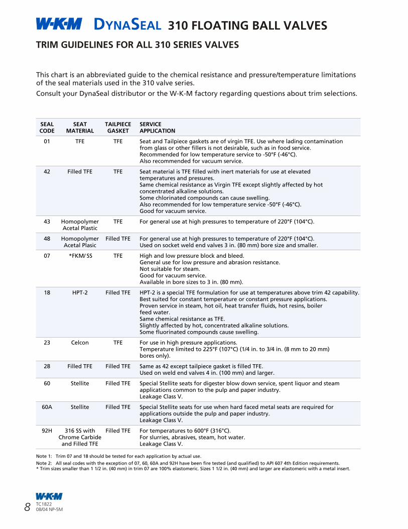
TRIM GUIDELINES FOR ALL 310 SERIES VALVES
SEAL SEAT TAILPIECE SERVICECODE MATERIAL GASKET APPLICATION
01 TFE TFE Seat and Tailpiece gaskets are of virgin TFE. Use where lading contamination from glass or other fillers is not desirable, such as in food service. Recommended for low temperature service to -50°F (-46°C).Also recommended for vacuum service.
42 Filled TFE TFE Seat material is TFE filled with inert materials for use at elevated temperatures and pressures.Same chemical resistance as Virgin TFE except slightly affected by hot concentrated alkaline solutions.Some chlorinated compounds can cause swelling. Also recommended for low temperature service -50°F (-46°C).Good for vacuum service.
43 Homopolymer TFE For general use at high pressures to temperature of 220°F (104°C).Acetal Plastic
48 Homopolymer Filled TFE For general use at high pressures to temperature of 220°F (104°C).Acetal Plasic Used on socket weld end valves 3 in. (80 mm) bore size and smaller.
07 *FKM/ SS TFE High and low pressure block and bleed.General use for low pressure and abrasion resistance.Not suitable for steam. Good for vacuum service.Available in bore sizes to 3 in. (80 mm).
18 HPT-2 Filled TFE HPT-2 is a special TFE formulation for use at temperatures above trim 42 capability.Best suited for constant temperature or constant pressure applications.Proven service in steam, hot oil, heat transfer fluids, hot resins, boilerfeed water. Same chemical resistance as TFE.Slightly affected by hot, concentrated alkaline solutions.Some fluorinated compounds cause swelling.
23 Celcon TFE For use in high pressure applications.Temperature limited to 225°F (107°C) (1/4 in. to 3/4 in. (8 mm to 20 mm) bores only).
28 Filled TFE Filled TFE Same as 42 except tailpiece gasket is filled TFE.Used on weld end valves 4 in. (100 mm) and larger.
60 Stellite Filled TFE Special Stellite seats for digester blow down service, spent liquor and steam applications common to the pulp and paper industry.Leakage Class V.
60A Stellite Filled TFE Special Stellite seats for use when hard faced metal seats are required for applications outside the pulp and paper industry.Leakage Class V.
92H 316 SS with Filled TFE For temperatures to 600°F (316°C).Chrome Carbide For slurries, abrasives, steam, hot water.and Filled TFE Leakage Class V.
Note 1: Trim 07 and 18 should be tested for each application by actual use.
Note 2: All seal codes with the exception of 07, 60, 60A and 92H have been fire tested (and qualified) to API 607 4th Edition requirements.* Trim sizes smaller than 1 1/2 in. (40 mm) in trim 07 are 100% elastomeric. Sizes 1 1/2 in. (40 mm) and larger are elastomeric with a metal insert.
This chart is an abbreviated guide to the chemical resistance and pressure/temperature limitationsof the seal materials used in the 310 valve series.
Consult your DynaSeal distributor or the W-K-M factory regarding questions about trim selections.
* Flow of water in U.S. Gallons per minute per 1 psi pressure drop across a fully open valve.(S) Short Pattern.(L) Long Pattern.
FLOW CHARACTERISTICS (C )*VV
WEIGHTS
VALVE MALE x FEMALE THREADED ENDSSIZE FULL PORT WEIGHTS REDUCED PORT WEIGHTS
in. (mm) MOP lb. kg lb. kg
1/2 (15) 3000 - - 3 1.36
1/2 (15) 5000 - - 3 1.36
3/4 (20) 3000 6 2.72 - -
3/4 (20) 3750 6 2.72 - -
1 (25) 3000 - - 7 3.18
1 (25) 3750 - - 7 3.18
SOCKET WELD ENDS
1/4 (8) 3000 2 0.91 - -
1/2 (15) 3000 - - 3 1.36
3/4 (20) 3000 6 2.72 - -
1 (25) 3000 - - 6 2.72
1 1/2 (40) 3000 19 8.62 - -
2 (50) 3000 - - 21 9.53
VALVE SIZE AND PORT SIZE THREADED VALVE PRESSURE CLASSin. (mm) END VALVES 150 300 600
1/4 x 1/4 (8 x 8) 9 - - -
3/8 x 3/8 (10 x 10) 9 - - -
1/2 x 3/8 (15 x 10) 5 - - -
1/2 x 1/2 (15 x 15) 16 16 14 -
3/4 x 1/2 (20 x 15) - 10 10 -
3/4 x 3/4 (20 x 20) 45 - - -
1 x 3/4 (25 x 20) 20 35 34 -
1 x 1 (25 x 25) 93 88 77 68
1 1/2 x 1 1/2 (40 x 40) 248 223 208 184
2 x 1 1/2 (50 x 40) 80 102 101 99
2 x 2 (50 x 50) 491 464 421 362
3 x 2 (80 x 50) 107 117 133 133
3 x 3 (80 x 80) 1099 1228 1042 928
4 x 3 (100 x 80) 322 359 410 406
4 x 4 (100 x 100) - 2118 2446 -
6 x 4 (150 x 100) - 390 391 (S) -
6 x 6 (150 x 150) - 5403 6644 (S) / 5468 (L) -
8 x 6 (200 x 150) - 1215 1219 (S) / 1215 (L) -
8 x 8 (200 x 200) - 11261 10782 -
10 x 8 (250 x 200) - 2671 2672 -
10 x 10 (250 x 250) - 17037 17438 -
12 x 10 (300 x 250) - 4881 4885 -
12 x 12 (300 x 300) - 26163 26702 -
14 x 12 (350 x 300) - 10580 10076 -
DYNASEAL 310 FLOATING BALL VALVES
9
DYNASEAL 310 FLOATING BALL VALVES
24 TC182208/04 NP-5M
TC182208/04 NP-5M
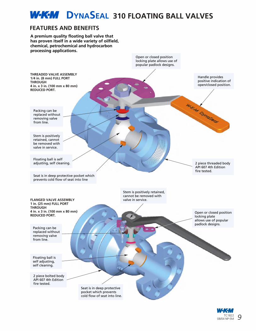
A premium quality floating ball valve that has proven itself in a wide variety of oilfield, chemical, petrochemical and hydrocarbon processing applications.
FEATURES AND BENEFITS
THREADED VALVE ASSEMBLY1/4 in. (8 mm) FULL PORTTHROUGH4 in. x 3 in. (100 mm x 80 mm)REDUCED PORT.
FLANGED VALVE ASSEMBLY1 in. (25 mm) FULL PORTTHROUGH4 in. x 3 in. (100 mm x 80 mm)REDUCED PORT.
Packing can bereplaced withoutremoving valvefrom line.
Handle providespositive indication ofopen/closed position.
Seat is in deep protective pocket whichprevents cold flow of seat into line
Stem is positivelyretained, cannotbe removed withvalve in service.
Floating ball is selfadjusting, self cleaning.
Packing can bereplaced withoutremoving valvefrom line.
Floating ball isself adjusting,self cleaning.
Seat is in deep protectivepocket which preventscold flow of seat into line.
Stem is positively retained,cannot be removed withvalve in service.
Open or closed positionlocking plateallows use of popularpadlock designs.
2 piece bolted bodyAPI 607 4th Editionfire tested.
2 piece threaded bodyAPI 607 4th Editionfire tested.
Open or closed positionlocking plate allows use ofpopular padlock designs.
WEIGHTS VALVE SIZE END FULL PORT WEIGHT REDUCED PORT WEIGHT
in. (mm) CONNECTION lb. kg lb. kg
1/4 (6) Threaded 1.50 0.68 - -
3/8 (10) Threaded 1.50 0.68 - -
1/2 (15) Threaded 1.50 0.68 1.50 0.68
1/2 (15) 150 (20 PN) Flanged (Unibody) 3.80 1.70 - -
1/2 (15) 300 (50 PN) Flanged (Unibody) 5.00 2.30
3/4 (20) Threaded 3.25 1.47 - -
3/4 (20) 150 (20 PN) Flanged (Unibody) - - 5.70 2.60
3/4 (20) 300 (50 PN) Flanged (Unibody) - - 7.50 3.40
1 (25) Threaded 5.00 2.30 3.00 1.36150 (20 PN) Flanged 8.50 3.86 6.3 2.86300 (50 PN) Flanged 12.00 5.44 - -
300 (50 PN) Flanged (Unibody) - - 8.80 4.00600 (100 PN) Flanged 32.00 14.50 - -
1 1/2 (40) Theaded 12.00 5.44 - -150 (20 PN) Flanged 17.00 7.71 - -300 (50 PN) Flanged 24.00 10.90 - -600 (100 PN) Flanged 32.00 14.50 - -
2 (50) Threaded 23.00 10.40 12.50 5.67150 (20 PN) Flanged 33.00 15.00 23.00 10.40300 (50 PN) Flanged 38.00 17.20 25.00 11.30
600 (100 PN) Flanged 47.00 21.30 33.00 15.00
3 (80) Threaded 56.00 25.40 36.00 16.30150 (20 PN) Flanged 64.00 29.00 51.00 23.10300 (50 PN) Flanged 81.00 36.70 76.00 35.00
600 (100 PN) Flanged 87.00 39.50 81.00 36.70
4 (100) Threaded - - 67.00 30.40150 (20 PN) Flanged - - 80.00 36.30300 (50 PN) Flanged - - 127.00 57.60
600 (100 PN) Flanged - - 130.00 59.00
VALVE SIZE END FULL PORT WEIGHT REDUCED PORT WEIGHTin. (mm) CONNECTION lb. kg lb. kg
4 (100) 150 (L) Flanged 113 51 - -WGA 300 (L) Flanged 144 65 - -
Butt Weld 94 43 - -600 Flanged 257 117 - -
6 (150) 150 (L) Flanged 162 73 - -150 (S) Flanged 144 65 125 57300 (L) Flanged 273 124 193 88
Butt Weld 189 86 139 63
6 (150) 150 (L) Flanged 176 80 - -WGA 150 (S) Flanged 158 72 133 60
300 (L) Flanged 313 142 223 101Butt Weld 203 92 154 70
600 Flanged 545 247 363 165
8 (200) 150 (L) Flanged 388 176 217 98150 (S) Flanged - - 197 89300 (S) Flanged 437 198 293 133
Butt Weld 328 149 237 108
8 (200) 150 (L) Flanged 428 194 231 105WGA 150 (S) Flanged - - 211 96
300 (L) Flanged 477 216 307 139WGA 300 (L) Flanged 517 235 - -
Butt Weld 368 167 251 114600 Flanged - - 648 294
10 (250) 150 (L) Flanged 695 315 451 205WGA 150 (L) Flanged 736 334 - -WGA 300 (L) Flanged 858 389 587 266WGA 300 (L) Flanged 953 432 - -
Butt Weld 610 277 365 166
12 (300) 150 (L) Flanged 943 428 791 359WGA 150 (L) Flanged 1038 471 - -WGA 300 (L) Flanged 1262 572 971 440WGA 300 (L) Flanged 1522 690 - -
Butt Weld 815 370 740 336
14 (350) 150 (L) Flanged - - 985 447WGA 300 (L) Flanged - - 1350 612
Butt Weld - - 1022 464
(S) Short Pattern. (L) Long Pattern.
DYNASEAL 310 FLOATING BALL VALVES
10
DYNASEAL 310 FLOATING BALL VALVES
23TC182208/04 NP-5M
TC182208/04 NP-5M
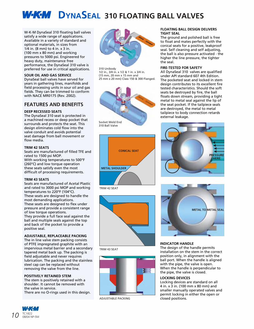
W-K-M DynaSeal 310 floating ball valves satisfy a wide range of applications. Available in a variety of standard and optional materials, in sizes from1/4 in. (8 mm) to 4 in. x 3 in.(100 mm x 80 mm) and working pressures to 5000 psi. Engineered for heavy duty, maintenance free performance, the DynaSeal 310 valve is preferred for use in critical applications.
SOUR OIL AND GAS SERVICEDynaSeal ball valves have served for years in gathering lines, manifolds and field processing units in sour oil and gas fields. They can be trimmed to conform with NACE MR0175 (Rev. 2002).
DEEP RECESSED SEATS The DynaSeal 310 seat is protected in a machined recess or deep pocket that surrounds and protects the seat. This design eliminates cold flow into the valve conduit and avoids potential seat damage from ball movement or flow media.
TRIM 42 SEATSSeats are manufactured of filled TFE and rated to 1500 psi MOP. With working temperatures to 500°F (260°C) and low torque operation these seats satisfy even the most difficult of processing requirements.
TRIM 43 SEATS Seats are manufactured of Acetal Plastic and rated to 3000 psi MOP and working temperatures to 220°F (104°C). These seats are designed to handle the most demanding applications. These seats are designed to flex under pressure and provide a consistent range of low torque operations. They provide a full face seal against the ball and multiple seals against the top and back of the pocket to provide a positive seal.
ADJUSTABLE, REPLACEABLE PACKINGThe in line valve stem packing consists of PTFE impregnated graphite with an impervious metal barrier and a secondary tapered metal back up. The packing is field adjustable and never requires lubrication. The packing and the stainless steel cap can be replaced without removing the valve from the line.
POSITIVELY RETAINED STEM The stem is positively retained with a shoulder. It cannot be removed with the valve in service. There are no O-rings used in this design.
FEATURES AND BENEFITS
310 Unibody1/2 in., 3/4 in. x 1/2 & 1 in. x 3/4 in.(15 mm, 20 mm x 15 mm and25 mm x 20 mm) Class 150 & 300 Flanged.
Socket Weld End310 Ball Valve
PRESSUREHERE
FLOATING BALL DESIGN DELIVERS TIGHT SEAL The ground and polished ball is free to float and mates perfectly with the conical seats for a positive, leakproof seal. Self cleaning and self adjusting, the ball is also pressure activated - the higher the line pressure, the tighter the seal.
FIRE-TESTED FOR SAFETYAll DynaSeal 310 valves are qualified under API standard 607 4th Edition. The pocketed seat and locked in stem design contributes to its excellent firetested characteristics. Should the soft seats be destroyed by fire, the ball floats down stream, providing a tight metal to metal seal against the lip of the seat pocket. If the tailpiece seals are destroyed, the metal to metaltailpiece to body connection retards external leakage.
TRIM 42 SEAT
INDICATOR HANDLEThe design of the handle permits installation on the stem in the correct position only, in alignment with the ball port. When the handle is aligned with the pipe, the valve is open.When the handle is perpendicular to the pipe, the valve is closed.
LOCKING DEVICES Locking devices are standard on all4 in. x 3 in. (100 mm x 80 mm) and smaller manually operated valves and permit locking in either the open or closed positions.
PRESSURE/TEMPERATURE LIMITS FOR 310 SERIES VALVE BODY ASSEMBLIES
FLANGED VALVESData is maximum working pressure ratings for the valve body assembly at various temperatures.
Practical pressure limitations according to actual service conditions are determined by the seal and tailpiece gasket materials.
THREADED VALVESBody trim code S8 and CS3 are suitable for service to -50°F (-46°C).
All other trims are limited to operating temperatures no lower than -20°F (-29°C)
These pressure/temperature ratings are in conformance with ASME/ANSI B16.5, B16.34.
MAXIMUM WORKING PRESSURES psig
BODY MATERIAL CODES
TEMP °F CS, CS2 & CS3 S1 & S8
VALVE CLASS 150 300 600 150 300 600
-20 to 100 285 740 1480 275 720 1440
150 272 707 1415 257 670 1340
200 260 675 1350 240 620 1240
250 245 665 1332 227 590 1180
300 230 655 1315 215 560 1120
350 215 645 1292 205 537 1075
400 200 635 1270 195 515 1030
450 185 617 1235 182 497 992
500 170 600 1200 170 480 955
550 155 575 1147 155 465 930
600 140 550 1095 140 450 905
MAXIMUM WORKING PRESSURES -bars (1 bar = 14.5 psi)
BODY MATERIAL CODES
TEMP °C CS, CS2 & CS3 S1 & S8
VALVE CLASS 20PN 50PN 100PN 20PN 50PN 100PN
-29 to 38 20 51 102 19 50 100
66 19 49 98 18 46 92
93 18 47 93 17 43 86
121 17 46 92 16 41 81
149 16 45 91 15 39 77
177 15 44 89 14 37 74
204 14 44 88 13 36 71
232 13 43 85 13 34 68
260 12 41 83 12 33 66
288 11 40 79 11 32 64
316 10 38 75 10 31 62
MAXIMUM WORKING PRESSURES - psig
TEMP °F BODY MATERIAL CODES
VALVE BORE CS, CS2 & CS3 S1 & S8
SIZE in. 1/4 - 3/8 1/2 - 3/4 1 2 3 1/4 - 3/8 1/2 - 3/4 1 2 3
-20 to 100 5000 3750 3000 2000 1500 5000 3750 3000 2000 1500
TEMP °C BODY MATERIAL CODES
VALVE BORE CS, CS2 & CS3 S1 & S8
SIZE mm 8 - 10 15 - 20 25 50 80 8 - 10 15 - 20 25 50 80
150 5000 3000 2300 1912 1434 5000 3000 2300 1861 1396
200 4550 2730 2025 1824 1368 4300 2575 1860 1722 1292
250 4490 2690 1997 1800 1350 4090 2450 1770 1639 1229
300 4430 2650 1970 1775 1333 3880 2325 1680 1556 1167
350 4350 2605 1935 1744 1310 3720 2330 1610 1491 1117
400 4275 2560 1900 1713 1287 3560 2140 1540 1426 1068
450 4155 2490 1847 1665 1252 3435 2065 1487 1377 1031
500 4040 2425 1795 1618 1216 3310 1990 1435 1328 995
550 3865 2315 1717 1548 1163 3220 1930 1395 1291 966
600 3690 2210 1640 1478 1110 3130 1875 1355 1254 938
MAXIMUM WORKING PRESSURE - bars (1 bar = 14.5 psi)
-29 to 38 345 259 207 138 103 345 259 207 138 103
66 345 207 159 132 99 345 258 159 128 96
93 314 188 140 126 94 297 178 128 119 89
121 310 186 138 124 93 282 169 122 113 85
149 306 183 136 122 92 268 160 116 107 80
177 300 180 133 120 90 257 154 111 103 77
204 295 177 131 118 89 246 148 106 98 74
232 287 172 127 115 86 237 142 103 95 71
260 279 167 124 112 84 228 137 99 92 69
288 267 160 118 107 80 222 133 96 89 67
316 254 152 113 102 77 216 129 93 86 65
TRIM 43 SEAT
METAL TO METAL SEAL
ADJUSTABLE PACKING
CONICAL SEAT
METAL SHOULDER
DYNASEAL 310 FLOATING BALL VALVES
11
DYNASEAL 310 FLOATING BALL VALVES
22 TC182208/04 NP-5M
TC182208/04 NP-5M
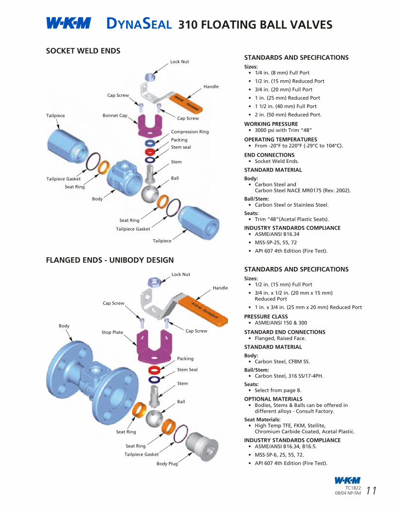
STANDARDS AND SPECIFICATIONS
Sizes:• 1/4 in. (8 mm) Full Port
• 1/2 in. (15 mm) Reduced Port
• 3/4 in. (20 mm) Full Port
• 1 in. (25 mm) Reduced Port
• 1 1/2 in. (40 mm) Full Port
• 2 in. (50 mm) Reduced Port.
WORKING PRESSURE • 3000 psi with Trim “48”
OPERATING TEMPERATURES• From -20°F to 220°F (-29°C to 104°C).
END CONNECTIONS• Socket Weld Ends.
STANDARD MATERIAL
Body:• Carbon Steel and
Carbon Steel NACE MR0175 (Rev. 2002).
Ball/Stem:• Carbon Steel or Stainless Steel.
Seats: • Trim “48”(Acetal Plastic Seats).
INDUSTRY STANDARDS COMPLIANCE• ASME/ANSI B16.34
• MSS-SP-25, 55, 72
• API 607 4th Edition (Fire Test).
SOCKET WELD ENDS
FLANGED ENDS - UNIBODY DESIGNSTANDARDS AND SPECIFICATIONS
Sizes:• 1/2 in. (15 mm) Full Port
• 3/4 in. x 1/2 in. (20 mm x 15 mm) Reduced Port
• 1 in. x 3/4 in. (25 mm x 20 mm) Reduced Port
PRESSURE CLASS • ASME/ANSI 150 & 300
STANDARD END CONNECTIONS• Flanged, Raised Face.
STANDARD MATERIAL
Body:• Carbon Steel, CF8M SS.
Ball/Stem:• Carbon Steel, 316 SS/17-4PH.
Seats:• Select from page 8.
OPTIONAL MATERIALS• Bodies, Stems & Balls can be offered in
different alloys - Consult Factory.
Seat Materials:• High Temp TFE, FKM, Stellite,
Chromium Carbide Coated, Acetal Plastic.
INDUSTRY STANDARDS COMPLIANCE• ASME/ANSI B16.34, B16.5.
• MSS-SP-6, 25, 55, 72.
• API 607 4th Edition (Fire Test).
Lock Nut
Tailpiece
Tailpiece Gasket
Handle
Compression Ring
Packing
Stem seal
Stem
Ball
Bonnet Cap
Seat Ring
Body
Seat Ring
Tailpiece Gasket
Tailpiece
Handle
Body
Cap Screw
Stem
Stem Seal
Packing
Ball
Seat Ring
Tailpiece Gasket
Body Plug
Lock Nut
Seat Ring
Stop Plate Cap Screw
Cap Screw
Cap Screw
PRESSURE/TEMPERATURE FOR ALL 310 SERIES VALVES
DynaSeal 310 Ball Valves are rated for high performance and long life.
The ratings shown here are based on tests which indicate good seat performance and acceptable wear.
This rating is determined by the lower of the valve's pressure or seat rating.
The seat rating is the maximum differential pressure to which the valve should be subjected on a continuous basis.OSeal codes 01, 02, 42 & 07 are suitable for vacuum service to 20 microns, absolute (minimum temperature 0 F (-18°C)).
SEAL CODE 01
Valve Port Size in. (mm)
Temp Temp 1/4 - 3/4 1 - 1 1/2 2 3 - 4 6 - 12
°F °C (80 - 20) (25 - 40) (50) (80 - 100) (150 - 300)
-50 to 100 -46 to 38 1500 1000 750 600 285
200 93 1500 1000 750 600 285
250 121 1400 900 700 550 150
300 149 1100 650 500 425 50
350 177 600 375 300 250 -
400 204 100 100 100 100 -
SEAL CODE 42
Valve Port Size in. (mm)
Temp Temp 1/4 - 1 1/2 2 3
°F °C (8 - 40) (50) (80)
-50 to 100 -46 to 38 1500 1500 740
200 93 1400 1325 740
250 121 1250 1150 740
300 149 1090 975 740
350 177 930 800 590
400 204 770 640 450
450 232 610 475 325
500 260 450 300 200
SEAL CODE 43, 48
Valve Port Size in. (mm)
Temp Temp 1/4 - 1 1/2 2 3 4 6
°F °C (8 - 40) (50) (80) (100) (150)
-50 to 100 -46 to 38 3000 2000 1500 1500 1500
200 93 3000 2000 1500 1500 1500
220 104 3000 2000 1375 1375 1375
SEAL CODE 07*
Valve Port Size in. (mm)
Temp Temp 1/4 - 1 1/2 2 3
°F °C (8 - 40) (50) (80)
-20 to 100 -29 to 38 740* 500* 285*
350 177 500 350 200
400 204 250 190 100
* Block and Bleed Range.
SEAL CODE 42, 28
Valve Port Size in. (mm)
Temp Temp 4 6 - 12
°F °C (100) (150 - 300)
-50 to 100 -46 to 38 740 740
250 121 740 675
300 149 740 550
350 177 590 410
400 204 400 300
450 232 325 175
500 260 200 65
SEAL CODE 18
Valve Port Size in. (mm)
Temp Temp 1/4 - 1 1/2 2 3 4 - 12
°F °C (8 - 40) (50) (80) (100 - 300)
-50 to 100 -46 to 38 * * * *
200 93 * * * *
250 121 1775 1250 * *
300 149 1650 1175 740 600
350 177 1575 1075 700 500
400 204 1500 1000 650 400
450 232 1300 875 600 300
500 260 1075 725 550 200
550 288 850 600 500 100
600 316 350 100 75 0
625 329 100 0 0 0
* On Application.
SEAL CODE 23
Valve Port Size in. (mm)
Temp Temp 1/4 - 3/8 1/2 - 3/4
°F °C (8 - 10) (15 - 20)
-50 to 100 -46 to 38 5000 3750
200 93 3250 2000
225 107 2500 1500
SEAL CODE 60, 60A, 92H
Temp Temp Trim Trim
°F °C 60/60A 92H
-50 to 100 -46 to 38 740 740
200 93 675 680
250 121 665 675
300 149 655 650
350 177 645 575
400 204 635 475
450 232 617 375
500 260 600 275
550 288 575 200
600 316 550 100
DYNASEAL 310 FLOATING BALL VALVES
12
DYNASEAL 310 FLOATING BALL VALVES
21TC182208/04 NP-5M
TC182208/04 NP-5M
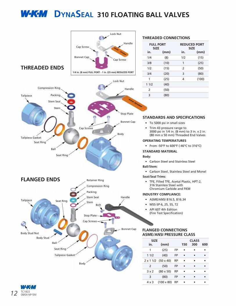
STANDARDS AND SPECIFICATIONS
• To 5000 psi in small sizes
• Trim 43 pressure range to3000 psi in 1/4 in. (8 mm) to 3 in. x 2 in.(80 mm x 50 mm) Threaded End Valves
OPERATING TEMPERATURES
• From -50°F to 600°F (-46°C to 316°C)
STANDARD MATERIAL
Body:
• Carbon Steel and Stainless Steel
Ball/Stem:
• Carbon Steel, Stainless Steel and Monel
Seat/Seal Trims:
• TFE, Filled TFE, Acetal Plastic, HPT-2,316 Stainless Steel withChromium Carbide and FKM
INDUSTRY COMPLIANCE:
• ASME/ANSI B16.5, B16.34
• MSS-SP-6, 25, 55, 72
• API 607 4th Edition(Fire Test Specification)
FLANGED CONNECTIONSASME/ANSI PRESSURE CLASS
SIZE CLASS in. (mm) 150 300 600
1 (25) FP • • •
1 1/2 (40) FP • • •
2 x 1 1/2 (50 x 40) RP • • •
2 (50) FP • • •
3 x 2 (80 x 50) RP • • •
3 (80) FP • • •
4 x 3 (100 x 80) RP • • •
FLANGED ENDS
THREADED ENDS
THREADED CONNECTIONS
FULL PORT REDUCED PORTSIZE SIZE
in. (mm) in. (mm)
1/4 (8) 1/2 (15)
3/8 (10) 1 (25)
1/2 (15) 2 (50)
3/4 (20) 3 (80)
1 (25) 4 (100)
1 1/2 (40)
2 (50)
3 (80)
Lock Nut
Handle
Stop Plate
Bonnet Cap
Body
Tailpiece
Compression Ring
Packing
Stem Seal
Stem
Tailpiece Gasket
Seat Ring
Ball
Seat Ring
Cap Screws
Tailpiece
Body Stud Nut
Body Stud
Stem
Stem Seal
Packing
Compression Ring
Retainer Ring
Ball
Seat Ring
Seat Ring
Tailpiece Gasket
Bonnet Cap
Handle
Stop Plate
Bolt
Body
Cap Screws
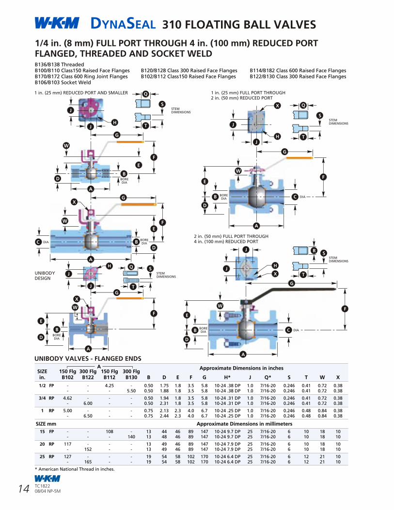
* Centerline-to-face dimension is half of dimension A, except:4 in. (100 mm) ASME/ANSI Class 150 Full Port - stem is offset 1/2 in. (12.7 mm) towards body end and6 in. (150 mm) ASME/ANSI Class 150 Full Port Long Pattern - stem is offset 2 1/2 in. (63.5 mm) towards body end.
FULL PORT DIMENSIONS
4 in. (100 mm) FULL PORT THROUGH 14 in. (350 mm) REDUCED PORTASME/ANSI CLASS 150, 300, 600 AND BUTT WELD 300
REDUCED PORT DIMENSIONS
mm
mm
A* ClassSIZE 150 RF 300 RF B C D E F G H J K L M N P R S T U V W X Y Z AAin. LONG SHORT LONG SHORT
B100 B102 B120 B122
10.50 - 4.00 6.00 6.45 8.63 9.88 36.00 7.56 1.250 8.00 2.80 7.88 0.250 10.84 9.15 - - 0.56 2.44 4.921 1.88 4.63 3/8-16NC 0.636 x 4 N/A N/A
- 15.88 4.00 6.00 6.45 8.63 9.88 36.00 7.56 1.250 10.00 2.80 8.12 0.250 10.84 9.15 - - 0.56 2.44 4.921 1.88 4.63 3/8-16NC 0.63
18.00 11.50 - 6.00 8.00 8.20 11.38 12.63 48.00 9.44 1.500 14.00 2.80 10.95 0.375 12.72 11.03 - - 0.56 2.44 4.921 1.88 4.63 3/8-16NC 0.638 x 6 N/A
- - 16.50 6.00 8.00 8.20 11.38 12.63 48.00 9.44 1.500 16.00 4.11 11.11 0.375 13.28 11.33 - - 0.56 2.44 4.921 1.88 4.63 3/8-16NC 0.63
21.00 - 8.00 10.00 10.10 16.38 - - 13.50 2.375 20.00 4.11 13.64 0.625 17.34 15.39 - - 0.68 4.00 5.512 3.50 8.25 1-8NC 1.1310 x 8 N/A N/A
- 22.38 8.00 10.00 10.10 16.38 - - 12.50 2.375 20.00 5.12 15.25 0.625 17.07 14.67 - - 0.75 3.00 - 3.50 8.25 1-8NC 1.13
24.00 - 10.00 12.00 11.78 18.50 - - 15.12 2.938 24.00 5.12 15.25 0.750 19.70 17.30 7.75 5.75 0.75 3.00 - 3.50 8.25 1-8NC 1.1312 x 10 N/A N/A
- 25.50 10.00 12.00 11.78 18.50 - - 15.12 2.938 20.00 8.31 17.61 0.750 21.24 17.30 7.75 5.75 0.75 3.00 - 3.50 8.25 1-8NC 1.13
- 12.00 14.00 13.97 20.13 - - 16.38 2.938 20.00 8.31 17.61 0.750 22.49 18.55 7.75 5.75 0.75 3.00 - 3.50 8.25 1-8NC 1.1314 x 12 N/A N/A N/A
30.00 12.00 14.00 13.97 20.13 - - 16.38 2.938 24.00 8.31 17.61 0.750 22.49 18.55 7.75 5.75 0.75 3.00 - 3.50 8.25 1-8NC 1.13
A* ClassSIZE 150 RF 300 RF B C D E F G H J K L M N P R S T U V W X Y Z AA
LONG SHORT LONG SHORTmmB100 B102 B120 B122
267 - 102 152 164 219 251 914 192 31.75 203 71 200 6.35 275 232 - - 14 62 124.99 48 118 3/8-16NC 16150 x 100 N/A N/A
- 403 102 152 164 219 251 914 192 31.75 254 71 206 6.35 275 232 - - 14 62 124.99 48 118 3/8-16NC 16
457 292 - 152 203 208 289 321 1219 240 38.10 356 71 278 9.53 323 280 - - 14 62 124.99 48 118 3/8-16NC 16200 x 150 N/A
- - 419 152 203 208 289 321 1219 240 38.10 406 104 282 9.53 337 288 - - 14 62 124.99 48 118 3/8-16NC 16
533 - 203 254 257 416 - - 343 60.33 508 104 346 15.88 440 391 - - 17 102 140.00 89 210 1-8NC 29250 x 200 N/A N/A
- 568 203 254 257 416 - - 318 60.33 508 130 387 15.88 434 373 - - 19 76 - 89 210 1-8NC 29
610 - 254 305 299 470 - - 384 74.63 610 130 387 19.05 500 439 197 146 19 76 - 89 210 1-8NC 29300 x 250 N/A N/A
- 648 254 305 299 470 - - 384 74.63 508 211 447 19.05 539 439 197 146 19 76 - 89 210 1-8NC 29
- 305 356 355 511 - - 416 74.63 508 211 447 19.05 571 471 197 146 19 76 - 89 210 1-8NC 29350 x 300 N/A N/A N/A
762 305 356 355 511 - - 416 74.63 610 211 447 19.05 571 471 197 146 19 76 - 89 210 1-8NC 29
A* Class 150 RF 300 RF 300
SIZE LONG SHORT LONG SHORT BW B C D E F G H J K L M N P R S T U V W X Y Z AAin. B110 B113 B128 B134 B150
9.00 - - 4.0 4.0 6.47 8.63 9.88 36.0 7.56 1.250 8.0 2.80 7.88 0.250 10.84 9.15 - - 0.56 2.44 4.921 1.88 4.63 3/8-16NC 0.634 N/A N/A
- 12.00 12.00 4.0 4.0 6.47 8.63 9.88 36.0 7.56 1.250 10.0 2.80 8.12 0.250 10.84 9.15 - - 0.56 2.44 4.921 1.88 4.63 3/8-16NC 0.63
15.50 10.50 - - 6.0 6.0 8.20 11.38 12.63 48.0 9.44 1.500 14.0 2.80 10.95 0.375 12.72 11.03 - - 0.56 2.44 4.921 1.88 4.63 3/8-16NC 0.636 N/A
- - 15.88 15.88 6.0 6.0 8.20 11.38 12.63 48.0 9.44 1.500 14.0 4.11 13.24 0.375 13.28 11.33 - - 0.56 2.44 4.921 1.88 4.63 3/8-16NC 0.63
18.00 - - - 8.0 8.0 9.95 16.38 - - 13.50 2.375 16.0 4.11 11.11 0.625 17.34 15.39 - - 0.68 4.00 5.512 3.50 8.25 1-8NC 1.138 N/A
- 19.75 16.50 16.50 8.0 8.0 9.97 16.38 - - 12.50 2.375 20.0 5.12 15.25 0.625 17.07 14.67 - - 0.75 3.00 - 3.50 8.25 1-8NC 1.13
21.00 - - - 10.0 10.0 11.63 18.50 - - 15.12 2.938 20.0 5.12 15.25 0.750 19.70 17.30 7.75 5.75 0.75 3.00 - 3.50 8.25 1-8NC 1.13
10 - N/A 22.38 - 22.00 10.0 10.0 11.65 18.50 - - 15.12 2.938 20.0 8.31 17.61 0.750 21.24 17.30 7.75 5.75 0.75 3.00 - 3.50 8.25 1-8NC 1.13
- - 18.00 - 10.0 10.0 11.65 18.50 - - 15.12 2.938 16.0 8.31 15.32 0.750 21.24 17.30 7.75 5.75 0.75 3.00 - 3.50 8.25 1-8NC 1.13
3.50 8.25 1-8NC 1.1324.00 - - 12.0 12.0 13.97 20.13 - - 16.38 2.938 20.0 8.31 17.61 0.750 22.49 18.55 7.75 5.75 0.75 3.00 -12 N/A N/A
- 25.50 25.00 12.0 12.0 13.97 20.13 - - 16.38 2.938 24.0 8.31 17.61 0.750 22.49 18.55 7.75 5.75 0.75 3.00 - 3.50 8.25 1-8NC 1.13
A* Class 150 RF 300 RF 300
SIZE LONG SHORT LONG SHORT BW B C D E F G H J K L M N P R S T U V W X Y Z AAin. B110 B113 B128 B134 B150
229 - - 102 102 164 219 251 914 192 31.75 203 71 200 6.35 275 232 - - 14 62 124.99 48 118 3/8-16NC 16100 N/A N/A
- 305 305 102 102 164 219 251 914 192 31.75 254 71 206 6.35 275 232 - - 14 62 124.99 48 118 3/8-16NC 16
394 267 - - 152 152 208 289 321 1219 240 38.10 356 71 278 9.53 323 280 - - 14 62 124.99 48 118 3/8-16NC 16150 N/A
- - 403 403 152 152 208 289 321 1219 240 38.10 356 104 336 9.53 337 280 - - 14 62 124.99 48 118 3/8-16NC 16
457 - - - 203 203 253 416 - - 343 60.33 406 104 282 15.88 440 391 - - 17 102 140.00 89 210 1-8NC 29200 N/A
- 502 419 419 203 203 253 416 - - 318 60.33 508 130 387 15.88 434 373 - - 19 76 - 89 210 1-8NC 29
533 - - - 254 254 295 470 - - 384 74.63 508 130 387 19.05 500 439 197 146 19 76 - 89 210 1-8NC 29
250 - N/A 568 - 559 254 254 295 467 - - 382 77.45 504 212 444 22.75 535 439 197 146 19 76 - 89 210 1-8NC 29
- - 457 - 254 254 296 470 - - 384 74.63 406 211 389 19.05 539 439 197 146 19 76 - 89 210 1-8NC 29
610 - - 305 305 355 511 - - 416 74.63 508 211 447 19.05 571 471 197 146 19 76 - 89 210 1-8NC 29300 N/A N/A
- 648 635 305 305 355 511 - - 416 74.63 610 211 447 19.05 571 471 197 146 19 76 - 89 210 1-8NC 29
Lock Nut
Handle
Bonnet Cap
Cap Screw
Cap Screw
1/4 in. (8 mm) FULL PORT - 1 in. (25 mm) REDUCED PORT
DYNASEAL 310 FLOATING BALL VALVES
13
DYNASEAL 310 FLOATING BALL VALVES
20 TC182208/04 NP-5M
TC182208/04 NP-5M
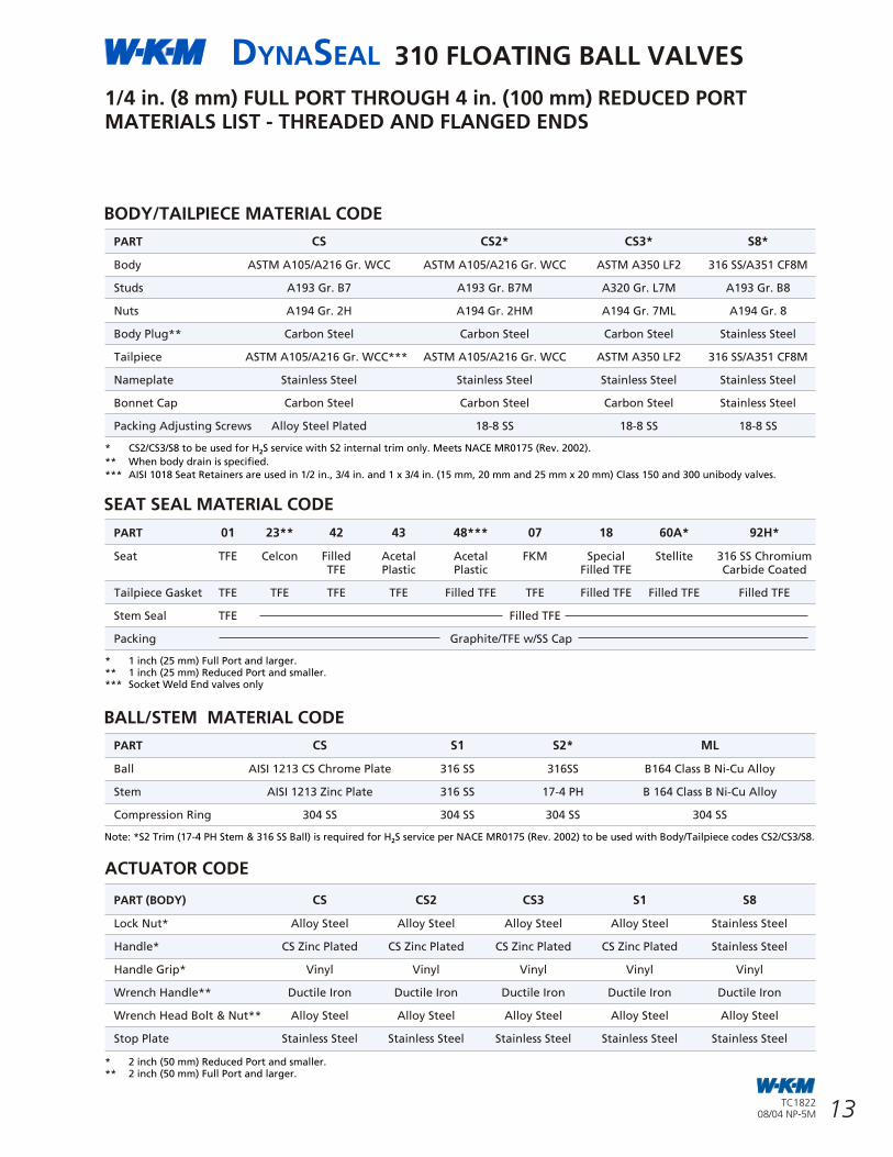
BODY/TAILPIECE MATERIAL CODE
PART CS CS2* CS3* S8*
Body ASTM A105/A216 Gr. WCC ASTM A105/A216 Gr. WCC ASTM A350 LF2 316 SS/A351 CF8M
Studs A193 Gr. B7 A193 Gr. B7M A320 Gr. L7M A193 Gr. B8
Nuts A194 Gr. 2H A194 Gr. 2HM A194 Gr. 7ML A194 Gr. 8
Body Plug** Carbon Steel Carbon Steel Carbon Steel Stainless Steel
Tailpiece ASTM A105/A216 Gr. WCC*** ASTM A105/A216 Gr. WCC ASTM A350 LF2 316 SS/A351 CF8M
Nameplate Stainless Steel Stainless Steel Stainless Steel Stainless Steel
Bonnet Cap Carbon Steel Carbon Steel Carbon Steel Stainless Steel
Packing Adjusting Screws Alloy Steel Plated 18-8 SS 18-8 SS 18-8 SS
1/4 in. (8 mm) FULL PORT THROUGH 4 in. (100 mm) REDUCED PORTMATERIALS LIST - THREADED AND FLANGED ENDS
SEAT SEAL MATERIAL CODE
PART 01 23** 42 43 48*** 07 18 60A* 92H*
Seat TFE Celcon Filled Acetal Acetal FKM Special Stellite 316 SS ChromiumTFE Plastic Plastic Filled TFE Carbide Coated
Tailpiece Gasket TFE TFE TFE TFE Filled TFE TFE Filled TFE Filled TFE Filled TFE
Stem Seal TFE Filled TFE
Packing Graphite/TFE w/SS Cap
BALL/STEM MATERIAL CODE
PART CS S1 S2* ML
Ball AISI 1213 CS Chrome Plate 316 SS 316SS B164 Class B Ni-Cu Alloy
Stem AISI 1213 Zinc Plate 316 SS 17-4 PH B 164 Class B Ni-Cu Alloy
Compression Ring 304 SS 304 SS 304 SS 304 SS
ACTUATOR CODE
PART (BODY) CS CS2 CS3 S1 S8
Lock Nut* Alloy Steel Alloy Steel Alloy Steel Alloy Steel Stainless Steel
Handle* CS Zinc Plated CS Zinc Plated CS Zinc Plated CS Zinc Plated Stainless Steel
Handle Grip* Vinyl Vinyl Vinyl Vinyl Vinyl
Wrench Handle** Ductile Iron Ductile Iron Ductile Iron Ductile Iron Ductile Iron
Wrench Head Bolt & Nut** Alloy Steel Alloy Steel Alloy Steel Alloy Steel Alloy Steel
Stop Plate Stainless Steel Stainless Steel Stainless Steel Stainless Steel Stainless Steel
* CS2/CS3/S8 to be used for H S service with S2 internal trim only. Meets NACE MR0175 (Rev. 2002).2
** When body drain is specified.
*** AISI 1018 Seat Retainers are used in 1/2 in., 3/4 in. and 1 x 3/4 in. (15 mm, 20 mm and 25 mm x 20 mm) Class 150 and 300 unibody valves.
* 1 inch (25 mm) Full Port and larger.** 1 inch (25 mm) Reduced Port and smaller.*** Socket Weld End valves only
Note: *S2 Trim (17-4 PH Stem & 316 SS Ball) is required for H S service per NACE MR0175 (Rev. 2002) to be used with Body/Tailpiece codes CS2/CS3/S8.2
* 2 inch (50 mm) Reduced Port and smaller.** 2 inch (50 mm) Full Port and larger.
4 in (100 mm) FULL PORT THROUGH 14 in. (350 mm) REDUCED PORTASME/ANSI CLASS 150, 300, 600 AND BUTT WELD 300
MOUNTING BRACKET4 in. FP - 8 in. RP(100 mm FP - 200 mm RP)Class 150/3008 in. FP & 10 in. RP(200 mm FP & 250 mm RP)Class 150
FULL PORT DIMENSIONS
SIZE in. A B C D H K L M P R
4 17.00 4.00 4.00 6.52 6.81 20.00 2.50 9.72 9.79 8.18
6 22.00 6.00 6.00 8.17 9.28 24.00 4.84 14.26 13.43 11.25
SIZE mm
100 432 102 102 166 173 508 64 247 249 208
150 559 152 152 208 236 610 123 362 341 286
REDUCED PORT DIMENSIONS
ASME/ANSI CLASS 600
SIZE in. A B C D H K L M P R
6 x 4 22.00 4.00 6.00 6.52 6.81 20.00 2.50 9.72 9.79 8.18
8 x 6 26.00 6.00 8.00 8.17 9.28 24.00 4.84 14.26 13.43 11.25
SIZE mm
150 x 100 559 102 152 166 173 508 64 247 249 208
200 x 150 660 152 203 208 236 610 123 362 341 286
VALVE WITH GEAR 4 in. (100 mm)THROUGH 8 in. x 6 in. (200 mm x 150 mm)CLASS 600
BORE
DIA
Z THREAD SIZE
D
F
DIA
DIA
B C
E
= KEY SIZE
HR
P
DIA
M
AA THREAD DEPTH
VALVE WITH WRENCH (LEVER)4 in. (100 mm) THROUGH14 in. x 12 in. (350 mm x 300 mm)Class 150/300
D
E
VALVE WITH WRENCH (LEVER)4 in. x 14 in. x 12 in.(100 mm x 350 mm x 300 mm)Class 150/300
BORE
DIAB
HE
BORE
DIAB
VALVE WITH GEAR4 in. x 14 in. x 12 in.(100 mm x 350 mm x 300 mmClass 150/300
V V
T
THROUGHHOLE DIA
THROUGHHOLE DIA
U
W
K
L
AA
N
J
G
X
Y
A A
G
P
S
ST
D
MOUNTING BRACKET8 in. FP & 10 in. RP (200 mm FP & 250 mm) RPClass 30010 in. FP - 14 in. RP(250 mm FP - 350 mm RP)Class 150/300
U
W
DYNASEAL 310 FLOATING BALL VALVES
14
DYNASEAL 310 FLOATING BALL VALVES
19TC182208/04 NP-5M
TC182208/04 NP-5M
A Approximate Dimensions in inchesSIZE 150 Flg 300 Flg 150 Flg 300 Flgin. B102 B122 B112 B130 B D E F G H* J Q* S T W X
1/2 FP - - 4.25 - 0.50 1.75 1.8 3.5 5.8 10-24 .38 DP 1.0 7/16-20 0.246 0.41 0.72 0.38- - - 5.50 0.50 1.88 1.8 3.5 5.8 10-24 .38 DP 1.0 7/16-20 0.246 0.41 0.72 0.38
3/4 RP 4.62 - - - 0.50 1.94 1.8 3.5 5.8 10-24 .31 DP 1.0 7/16-20 0.246 0.41 0.72 0.38- 6.00 - - 0.50 2.31 1.8 3.5 5.8 10-24 .31 DP 1.0 7/16-20 0.246 0.41 0.72 0.38
1 RP 5.00 - - - 0.75 2.13 2.3 4.0 6.7 10-24 .25 DP 1.0 7/16-20 0.246 0.48 0.84 0.38- 6.50 - - 0.75 2.44 2.3 4.0 6.7 10-24 .25 DP 1.0 7/16-20 0.246 0.48 0.84 0.38
SIZE mm Approximate Dimensions in millimeters
15 FP - - 108 - 13 44 46 89 147 10-24 9.7 DP 25 7/16-20 6 10 18 10- - - 140 13 48 46 89 147 10-24 9.7 DP 25 7/16-20 6 10 18 10
20 RP 117 - - - 13 49 46 89 147 10-24 7.9 DP 25 7/16-20 6 10 18 10- 152 - - 13 49 46 89 147 10-24 7.9 DP 25 7/16-20 6 10 18 10
25 RP 127 - - - 19 54 58 102 170 10-24 6.4 DP 25 7/16-20 6 12 21 10- 165 - - 19 54 58 102 170 10-24 6.4 DP 25 7/16-20 6 12 21 10
* American National Thread in inches.
UNIBODY VALVES - FLANGED ENDS
1/4 in. (8 mm) FULL PORT THROUGH 4 in. (100 mm) REDUCED PORTFLANGED, THREADED AND SOCKET WELDB136/B138 ThreadedB100/B110 Class150 Raised Face Flanges B120/B128 Class 300 Raised Face Flanges B114/B182 Class 600 Raised Face FlangesB170/B172 Class 600 Ring Joint Flanges B102/B112 Class150 Raised Face Flanges B122/B130 Class 300 Raised Face FlangesB106/B103 Socket Weld
BOREDIA
UNIBODYDESIGN
BODY/TAILPIECE MATERIAL CODE
PART CS CS2* S1 S8*
Body A216 Gr. WCC A216 Gr. WCC A351 Gr. CF8M A351 Gr. CF8M
Studs A193 Gr. B7 A193 Gr. B7 A193 Gr. B7 Plated A193 Gr. B8
Nuts A194 Gr. 2H A194 Gr. 2H A194 Gr. 2H Plated A193 Gr. B8
Body Drain Fitting Carbon Steel Stainless Steel Stainless Steel Stainless Steel
Tailpiece** ASTM A105/A216 Gr. WCC ASTM A105/A216 Gr. WCC A351 Gr. CF8M A351 CF8M
Packing Adjust Studs A193 Gr. B7 A193 Gr. B7 A193 Gr. B7 Plated A193 Gr. B8
Packing Adjust Nuts A194 Gr. 2H A194 Gr. 2H A194 Gr. 2H Plated A194 Gr. B8
Packing Adjusting Screws*** Alloy Steel Alloy Steel Alloy Steel Plated Stainless Steel
Bonnet Cap A216 Gr. WCC Plated A216 Gr. WCC Plated A216 Gr. WCC Plated A351 Gr. CF8M
* CS2 and S8 to be used for H S service. Only use with S1 internal trim. Meets NACE MR0175 (Rev. 2002). Standard trim for ASME/ANSI Class 600.2
** 8 in. (200 mm) through 14 in. x 12 in. (350 mm x 300 mm) ASME/ANSI Class 150 and 300. Only available in A216 Gr. WCC material.*** Use only for 4 in. (100 mm) through 8 in. x 6 in. (200 mm x 150 mm) ASME/ANSI Class 150 and 300.
ASME/ANSI CLASS 150, 300 AND 6004 in. (100 mm) FULL PORT THROUGH14 in. x 12 in. (350 mm x 300 mm) REDUCED PORTMATERIALS LIST
SEAT/SEAL MATERIAL CODE
PART 01 42 43* 18 28 60 60A 92H
Seat TFE Filled - Special Filled Solid Stellite or 316 SS with 316 SS ChromiumTFE Filled TFE TFE Stellite Hard Facing Carbide Coat
Seat Seal - - - - - - Braided Graphite Filled TFE
Tailpiece Gasket TFE TFE FKM O-Ring Filled TFE Filled TFE Filled TFE Filled TFE Filled TFE
Stem Gasket TFE Filled TFE Nylon Washer Filled TFE Filled TFE Filled TFE Filled TFE Filled TFE
Packing Graphite/TFE with SS Cap FKM O-Ring** Graphite/ TFE with SS Cap
BALL/STEM MATERIAL CODE
PART CS S1 S2* ML
Ball AISTM A105 Hard Chrome Plate 316 SS 316 SS B164 Class B Ni-Cu Alloy
Grounding Spring 304 SS 304 SS 304 SS 304 SS
Stem Carbon Steel ENP 316 SS 17-4 SS B164 Class B Ni-Cu Alloy
Compression Ring 304 SS 304 SS 304 SS 304 SS
Stem Retainer Pin Carbon Steel 316 SS 316 SS 316 SS
Stem Retainer Pipe Plug Carbon Steel 316 SS 316 SS 316 SS
* Specify Code 43 as standard trim for ASME/ANSI Class 600. Seal set consists of: Acetal Plastic Seats, High Fluorine FKM O-Ring for Tailpiece & stem.** Class 600 Valves have FKM O-Ring stem seal.
* Specify Code S2 as standard trim for ASME/ANSI Class 600.
ACTUATOR CODES*
PART (Body) For All Body - Tailpiece Trim Codes
Mounting Bracket Ductile Iron
Adapter Plate Carbon Steel
Stem Adapter Carbon Steel
Bolting Alloy Steel
Key Carbon Steel
Set Screw Carbon Steel
Actuator As Selected
Handwheel Carbon Steel
ACTUATOR CODES** ACTUATOR CODES (WRENCHES)***
* 10 in. through 14 in. x 12 in.(250 mm through 350 mm x 300 mm)ASME/ANSI Class 150 and 300.
** 4 in. through 8 in.(100 mm through 200 mm)ASME/ANSI Class 600.
*** 4 in. through 8 in. x 6 in.(100 mm through 200 mm x 150 mm)ASME/ANSI Class 150 and 300.
PART (Body) Worm Gear - For AllBody Material Codes
Mounting Bracket Carbon Steel
Bolting Carbon Steel
Set Screw Carbon Steel
Stem Adapter Carbon Steel
Actuator As Selected
Handwheel Carbon Steel
PART (Body) Wrench - For AllBody Material Codes
Wrench Head Steel
Wrench Handle Carbon Steel
Wrench Handle Pin Carbon Steel
Cap Screw Alloy Steel
Stop plate Carbon Steel
1 in. (25 mm) FULL PORT THROUGH2 in. (50 mm) REDUCED PORT
XJ
J
H
DIA
2 in. (50 mm) FULL PORT THROUGH4 in. (100 mm) REDUCED PORT
BOREDIA
1 in. (25 mm) REDUCED PORT AND SMALLER
DIABOREDIA
J
JH
G
G
A
F
E
D
W
C B
A
A
G
J
JH
X
G
W
E
D
A
B C
G
FW
E
B
A
C
D
E
D
BOREDIA
B
J
J
F
F
Q
S
T
STEMDIMENSIONS
Q
S
T
STEMDIMENSIONS
S
T
STEMDIMENSIONS
R
T
W
S
X
W
X
QSTEMDIMENSIONS
DIA
BOREDIA
B
H
FD
E
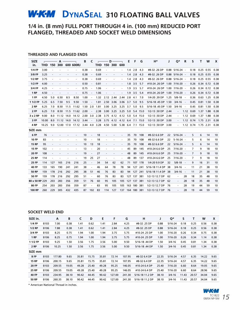
DYNASEAL 310 FLOATING BALL VALVES
15
DYNASEAL 310 FLOATING BALL VALVES
18 TC182208/04 NP-5M
TC182208/04 NP-5M
1/4 in. (8 mm) FULL PORT THROUGH 4 in. (100 mm) REDUCED PORTFLANGED, THREADED AND SOCKET WELD DIMENSIONS
* American National Thread in inches.
SIZE A B C D E F G H* J Q* R S T W Xin. THD 150 300 600 600RJ THD 150 300 600
1/4 FP 3.00 - - - - 0.38 - 0.69 - - - 1.4 2.8 4.3 #8-32 .26 DP 0.88 5/16-24 - 0.18 0.25 0.55 0.38
3/8 FP 3.25 - - - - 0.38 - 0.69 - - - 1.4 2.8 4.3 #8-32 .26 DP 0.88 5/16-24 - 0.18 0.25 0.55 0.38
1/2 RP 3.75 - - - - 0.38 - 0.69 - - - 1.4 2.8 4.3 #8-32 .26 DP 0.88 5/16-24 - 0.18 0.25 0.55 0.38
1/2 FP 4.00 - - - - 0.50 - 0.81 - - - 1.8 3.5 5.7 #10-24 .26 DP 1.00 7/16-20 - 0.26 0.34 0.72 0.38
3/4 FP 4.25 - - - - 0.75 - 1.06 - - - 1.9 3.5 5.7 #10-24 .26 DP 1.00 7/16-20 - 0.26 0.34 0.72 0.38
1 RP 4.50 - - - - 0.75 - 1.06 - - - 1.9 3.5 5.4 #10-24 .26 DP 1.00 7/16-20 - 0.26 0.34 0.72 0.38
1 FP 4.50 5.0 6.50 8.5 8.50 1.00 - 1.32 2.12 2.44 2.44 2.8 4.1 7.0 1/4-20 .39 DP 1.25 5/8-18 - 0.36 0.63 1.25 0.38
1 1/2 FP 5.25 6.5 7.50 9.5 9.50 1.50 - 1.81 2.50 3.06 3.06 3.7 5.0 9.5 5/16-18 .45 DP 1.50 3/4-16 - 0.45 0.81 1.50 0.38
2 RP 6.25 7.0 8.50 11.5 11.62 1.50 2.0 1.81 3.00 3.25 3.25 3.7 5.0 9.5 5/16-18 .45 DP 1.50 3/4-16 - 0.45 0.81 1.50 0.38
2 FP 6.25 7.0 8.50 11.5 11.62 2.00 - 2.38 3.00 3.25 3.25 5.0 5.4 15.0 1/2-13 .50 DP 2.44 - 1.12 0.69 1.37 1.88 0.38
3 x 2 RP 9.00 8.0 11.12 14.0 14.12 2.00 3.0 2.38 3.75 4.12 4.12 5.0 5.4 15.0 1/2-13 .50 DP 2.44 - 1.12 0.69 1.37 1.88 0.38
3 FP 10.00 8.0 11.12 14.0 14.12 3.44 - 3.28 3.75 4.12 4.12 6.4 7.1 15.0 1/2-13 .50 DP 3.00 - 1.12 0.74 1.75 2.31 0.38
4 RP 10.25 9.0 12.00 17.0 17.12 3.44 4.0 3.28 4.50 5.00 5.38 6.4 7.1 15.0 1/2-13 .50 DP 3.00 - 1.12 0.74 1.75 2.31 0.38
SIZE mm
6 FP 76 - - - - 10 - 18 - - - 35 70 108 #8-32 6.6 DP 22 5/16-24 - 5 6 14 10
10 FP 83 - - - - 10 - 18 - - - 35 70 108 #8-32 6.6 DP 22 5-16-24 - 5 6 14 10
15 RP 95 - - - - 10 13 18 - - - 35 70 108 #8-32 6.6 DP 22 5/16-24 - 5 6 14 10
15 FP 102 - - - - 13 - 20 - - - 45 89 145 #10-24 6.6 DP 25 7/16-20 - 7 9 18 10
20 FP 108 - - - - 19 - 27 - - - 48 89 145 #10-24 6.6 DP 25 7/16-20 - 7 9 18 10
25 RP 114 - - - - 19 25 27 - - - 48 89 137 #10-24 6.6 DP 25 7/16-20 - 7 9 18 10
25 FP 114 127 165 216 216 25 - 34 54 62 62 71 107 178 1/4-20 9.9 DP 32 5/8-18 - 9 16 31 10
40 FP 133 165 190 241 241 38 - 46 64 78 78 94 127 241 5/16-18 11.4 DP 38 3/4-16 - 11 21 38 10
50 RP 159 178 216 292 295 38 51 46 76 83 83 94 127 241 5/16-18 11.4 DP 38 3/4-16 - 11 21 38 10
50 FP 159 178 216 292 295 51 - 60 76 83 83 127 137 381 1/2-13 12.7 DP 62 - 28 18 35 48 10
80 x 50 RP 229 203 283 356 359 51 76 60 95 105 105 127 137 381 1/2-13 12.7 DP 62 - 28 18 35 48 10
80 FP 254 203 283 356 359 87 - 83 95 105 105 163 180 381 1/2-13 12.7 DP 76 - 28 19 44 59 10
100 RP 260 229 305 432 435 87 102 83 114 127 137 164 180 381 1/2-13 12.7 DP 76 - 28 19 44 59 10
SOCKET WELD END
SIZE in. A B C D E F G H J Q* S T W X
1/4 FP B103 7.00 0.38 1.41 0.62 1.41 2.84 4.25 #8-32 .25 DP 0.88 5/16-24 0.18 0.25 0.56 0.38
1/2 RP B106 7.88 0.38 1.41 0.62 1.41 2.84 4.25 #8-32 .25 DP 0.88 5/16-24 0.18 0.25 0.56 0.38
3/4 FP B103 8.25 0.75 1.94 1.00 1.94 3.75 5.75 #10-24 .25 DP 1.00 7/16-20 0.26 0.34 0.75 0.38
1 RP B106 8.25 0.75 1.94 1.00 1.94 3.75 5.75 #10-24 .25 DP 1.00 7/16-20 0.26 0.34 1.14 0.38
1 1/2 FP B103 9.25 1.50 3.56 1.75 3.56 5.00 9.50 5/16-18 .44 DP 1.50 3/4-16 0.45 0.81 1.34 0.38
2 RP B106 10.25 1.50 3.56 1.75 3.56 5.00 9.50 5/16-18 .44 DP 1.50 3/4-16 0.45 0.81 1.34 0.38
SIZE mm
8 FP B103 177.80 9.65 35.81 15.75 35.81 72.14 107.95 #8-32 6.4 DP 22.35 5/16-24 4.57 6.35 14.22 9.65
15 RP B106 200.15 9.65 35.81 15.75 35.81 72.14 107.95 #8-32 6.4 DP 22.35 5/16-24 4.57 6.35 14.22 9.65
20 FP B103 209.55 19.05 49.28 25.40 49.28 95.25 146.05 #10-24 6.4 DP 25.40 7/16-20 6.60 8.64 19.05 9.65
25 RP B106 209.55 19.05 49.28 25.40 49.28 95.25 146.05 #10-24 6.4 DP 25.40 7/16-20 6.60 8.64 28.96 9.65
40 FP B103 234.95 38.10 90.42 44.45 90.42 127.00 241.30 5/16-18 11.2 DP 38.10 3/4-16 11.43 20.57 34.04 9.65
50 RP B106 260.35 38.10 90.42 44.45 90.42 127.00 241.30 5/16-18 11.2 DP 38.10 3/4-16 11.43 20.57 34.04 9.65
ASME/ANSI PRESSURE CLASS
SIZE CLASS in. (mm) 150 300 600 300 BW
4 (100) FP • • • •
6 x 4 (150 x 100) RP • • •
6 (150) FP • • • •
8 x 6 (200 x 150) RP • • •
8 (200) FP • • •
10 x 8 (250 x 200) RP • •
10 (250) FP • • •
12 x 10 (300 x 250) RP • •
12 (300) FP • • •
14 x 12 (350 x 300) RP • •
STANDARDS AND SPECIFICATIONS
ASME/ANSI CLASS 150, 300 AND 300 BUTT WELD
ASME/ANSI CLASS 150, 300, 600 AND 300 BW
OPERATING TEMPERATURES
• From -50°F to 600°F (-46°F to 316°C)
STANDARD MATERIALS
• Body: Carbon Steel and Stainless Steel
• Ball/Stem: Carbon Steel, Stainless Steel & Monel
INDUSTRY COMPLIANCE
• ASME/ANSI B16.5, B16.34
• MSS-SP-25, 55, 72
• API 607 4th Edition (Fire Test Specifications)
Ball
GEAR OPERATOR OPTION
ASME/ANSI CLASS 600
Stem Gasket
Stem
Body Stud
Body Stud Nut
Tailpiece Gasket
Tailpiece
Stem Retainer Pin
Pipe Plug
Stem Packing
Compression Ring
Bonnet Cap
Cap Screw
Stop Plate
Key
Body
Ball
Stem Gasket
Stem
Body Stud
Body Stud Nut
Seat Rings
Tailpiece Gasket
Tailpiece
Stem O-Ring
Stud
Key
Washer
NutBody
Handwheel
Worm Gear Operator
Ground Spring
Drain Fitting
Seat Rings
THREADED AND FLANGED ENDS
GroundSpring
Drain Fitting
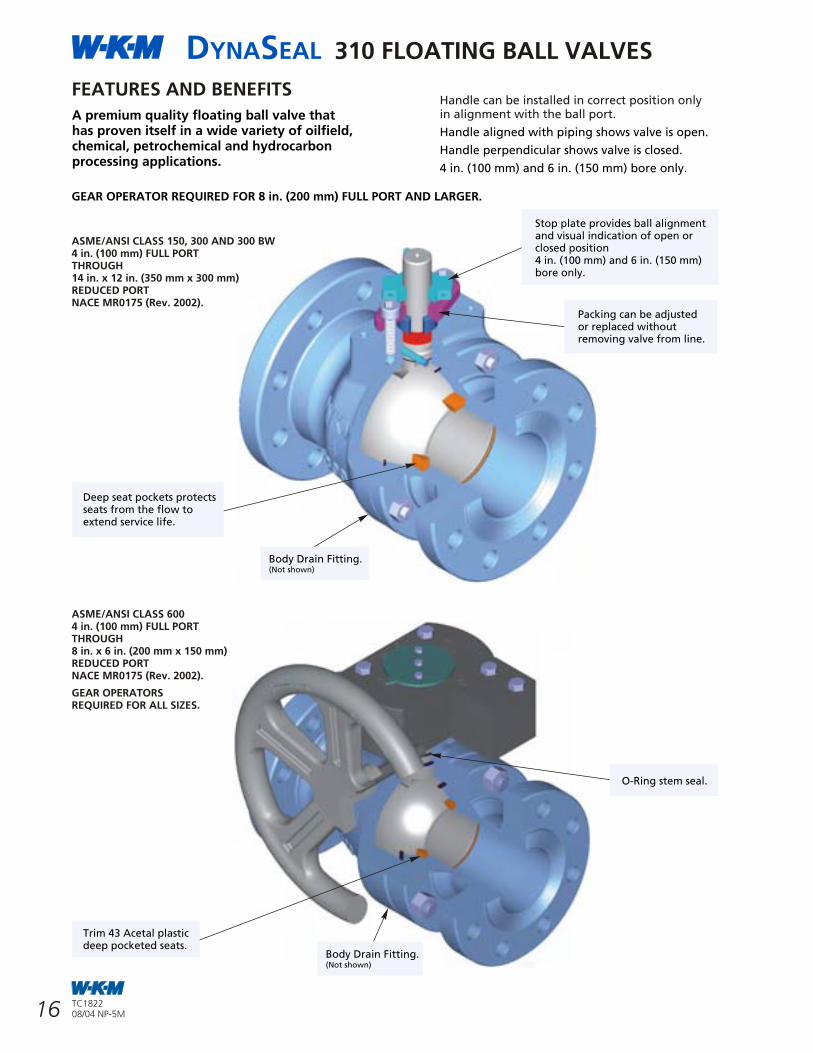
DYNASEAL 310 FLOATING BALL VALVES
16
DYNASEAL 310 FLOATING BALL VALVES
17TC182208/04 NP-5M
TC182208/04 NP-5M
W-K-M DynaSeal 310 floating ball valves satisfy a wide range of applications. Available in a variety of standard and optional materials, they may be specified in sizes from 4 in. (100 mm) to 14 in. (350 mm) and ASME/ANSI Class 150 and 300. ASME/ANSI Class 600 is available in sizes 4 in. (100 mm) through 8 in. x 6 in. (200 mm x 150 mm).Engineered for heavy duty, maintenance free performance, the DynaSeal 310 is commonly selected for a variety of applications in virtually any industry.
DynaSeal is the workhorse of the refining industry.
HIGH TEMPERATURE SERVICESpecial high temperature trims are available for DynaSeal 310 ball valves which provide for service to 600°F (316°C). This trim is excellent for steam service, hot oil, heat transfer fluids, boiler feed-water and similar applications.
LOW TEMPERATURE SERVICEStandard trims accomodate temperatures to -20°F (-29°C).For temperatures to -50°F (-46°C);please consult factory.
MAINTENANCE FREE PERFORMANCEUnder most conditions, the DynaSeal 310 floating ball valve will provide years of trouble free service with no maintenance required.In some severe applications, such as handling extremely abrasive slurries at high temperature, it may be necessary to replace the seats occasionally.Seat and seal kits are available and replacement can be done easily with ordinary tools.
SOUR OIL AND GAS SERVICEDynaSeal ball valves have served for years in gathering lines, manifolds and field processing units in sour oil and gas fields. They can be trimmed to conform with NACE MR0175 (Rev. 2002).
CHEMICAL & PETROCHEMICAL PLANTSThe list of chemical and petrochemical applications for DynaSeal ball valves is limitless. They are serving in many plastic plants handling such slurries as 40% vinyl chloride, in high pressure catalyst lines and in processes handling dry lading such as polyethylene and polystyrene powders.There are hundreds of applications in such plants where DynaSeals are providing efficient service.
REFINING
The many metal seats, seals and available trims offer the versatility needed to handle the wide variety of products used in the refining process.
TEFLON BODY SEALA Teflon body seal is used between the valve body and tailpiece.
DEEP RECESSED SEATS The seat is recessed into a deep machined pocket, which serves to surround and protect the seat on all sides. This design eliminates cold flow into the valve conduit where it can be damaged by the action of the ball or the flow medium.The result is extremely long service life.
ADJUSTABLE, REPLACEABLE PACKINGThe inline valve stem packing through ASME/ANSI Class 300 consists of PTFE impregnated graphite with an impervious metal barrier and a secondary tapered metal backup. The packing is field adjustable and never requires lubrication.The packing and the stainless steel cap can be replaced without removing the valve from line.
FUGITIVE EMISSIONSDynaSeal 310 ball valves through ASME/ANSI Class 300 can be supplied and certified to meet the requirements of fugitive emissions as regulated by The 1990 Amendment to The Clean Air Act.
POSITIVELY RETAINED STEMThe stem is positively retained and cannot be removed with the valve in service.
INDICATOR HANDLEThe design of the handle ASME/ANSI Class 300 permits installation on the stem in the correct position only,in alignment with the ball port.When the handle is aligned with the pipe, the valve is open.When the handle is perpendicular to the pipe, the valve is closed.
FLOATING BALL DESIGN DELIVERS TIGHT SEALThe ground and polished ball is freeto float and mates perfectly with the conical seats for a positive, leakproof seal. Self cleaning and self adjusting, the ball is also pressure activated.The higher the line pressure, the tighter the seal.
ACTUATION-FRIENDLYA variety of actuator types can be easily installed, includingpneumatic, hydraulic, diaphragm, vane, electro-mechanical andelectro-hydraulic.
FIRE-TESTED FOR SAFETYAll DynaSeal 310 valves arequalified under API standard 607 4th Edition. The pocketed seat and locked in stem design contributes to its excellent fire tested characteristics. Should the soft seats be destroyed by fire, the ball floats down stream, providing a tight metal to metal seal against the lip of the seat pocket. If the tailpiece seals are destroyed, the metal to metal tailpiece to body connection retards external leakage.
W-K-M DynaSeal 310 Ball Valvewith Pneumatic Actuator
GEAR MOUNTING BRACKETS FOR:
4 in. FP - 8 in. RP(100 mm FP - 200 mm RP)Class 150/300
8 in. FP & 10 in. RP(200 mm FP & 250 mm RP)Class 150
8 in. FP & 10 in. RP(200 mm FP & 250 mm RP)Class 300
10 in. FP - 14 in. RP(250 mm FP - 350 mm RP)Class 150/300
FEATURES AND BENEFITS
A premium quality floating ball valve that has proven itself in a wide variety of oilfield, chemical, petrochemical and hydrocarbon processing applications.
FEATURES AND BENEFITS
Stop plate provides ball alignmentand visual indication of open orclosed position4 in. (100 mm) and 6 in. (150 mm)bore only.
Handle can be installed in correct position onlyin alignment with the ball port.
Handle aligned with piping shows valve is open.
Handle perpendicular shows valve is closed.
4 in. (100 mm) and 6 in. (150 mm) bore only.
Packing can be adjustedor replaced withoutremoving valve from line.
ASME/ANSI CLASS 150, 300 AND 300 BW4 in. (100 mm) FULL PORTTHROUGH14 in. x 12 in. (350 mm x 300 mm)REDUCED PORTNACE MR0175 (Rev. 2002).
ASME/ANSI CLASS 6004 in. (100 mm) FULL PORTTHROUGH8 in. x 6 in. (200 mm x 150 mm)REDUCED PORTNACE MR0175 (Rev. 2002).
GEAR OPERATORSREQUIRED FOR ALL SIZES.
GEAR OPERATOR REQUIRED FOR 8 in. (200 mm) FULL PORT AND LARGER.
Deep seat pockets protectsseats from the flow toextend service life.
Trim 43 Acetal plasticdeep pocketed seats.
Body Drain Fitting.(Not shown)
O-Ring stem seal.
Body Drain Fitting.(Not shown)
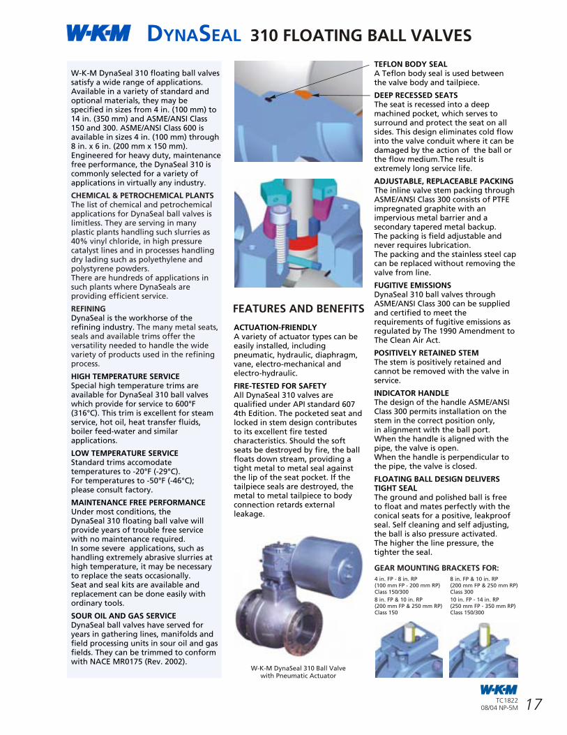
DYNASEAL 310 FLOATING BALL VALVES
16
DYNASEAL 310 FLOATING BALL VALVES
17TC182208/04 NP-5M
TC182208/04 NP-5M
W-K-M DynaSeal 310 floating ball valves satisfy a wide range of applications. Available in a variety of standard and optional materials, they may be specified in sizes from 4 in. (100 mm) to 14 in. (350 mm) and ASME/ANSI Class 150 and 300. ASME/ANSI Class 600 is available in sizes 4 in. (100 mm) through 8 in. x 6 in. (200 mm x 150 mm).Engineered for heavy duty, maintenance free performance, the DynaSeal 310 is commonly selected for a variety of applications in virtually any industry.
DynaSeal is the workhorse of the refining industry.
HIGH TEMPERATURE SERVICESpecial high temperature trims are available for DynaSeal 310 ball valves which provide for service to 600°F (316°C). This trim is excellent for steam service, hot oil, heat transfer fluids, boiler feed-water and similar applications.
LOW TEMPERATURE SERVICEStandard trims accomodate temperatures to -20°F (-29°C).For temperatures to -50°F (-46°C);please consult factory.
MAINTENANCE FREE PERFORMANCEUnder most conditions, the DynaSeal 310 floating ball valve will provide years of trouble free service with no maintenance required.In some severe applications, such as handling extremely abrasive slurries at high temperature, it may be necessary to replace the seats occasionally.Seat and seal kits are available and replacement can be done easily with ordinary tools.
SOUR OIL AND GAS SERVICEDynaSeal ball valves have served for years in gathering lines, manifolds and field processing units in sour oil and gas fields. They can be trimmed to conform with NACE MR0175 (Rev. 2002).
CHEMICAL & PETROCHEMICAL PLANTSThe list of chemical and petrochemical applications for DynaSeal ball valves is limitless. They are serving in many plastic plants handling such slurries as 40% vinyl chloride, in high pressure catalyst lines and in processes handling dry lading such as polyethylene and polystyrene powders.There are hundreds of applications in such plants where DynaSeals are providing efficient service.
REFINING
The many metal seats, seals and available trims offer the versatility needed to handle the wide variety of products used in the refining process.
TEFLON BODY SEALA Teflon body seal is used between the valve body and tailpiece.
DEEP RECESSED SEATS The seat is recessed into a deep machined pocket, which serves to surround and protect the seat on all sides. This design eliminates cold flow into the valve conduit where it can be damaged by the action of the ball or the flow medium.The result is extremely long service life.
ADJUSTABLE, REPLACEABLE PACKINGThe inline valve stem packing through ASME/ANSI Class 300 consists of PTFE impregnated graphite with an impervious metal barrier and a secondary tapered metal backup. The packing is field adjustable and never requires lubrication.The packing and the stainless steel cap can be replaced without removing the valve from line.
FUGITIVE EMISSIONSDynaSeal 310 ball valves through ASME/ANSI Class 300 can be supplied and certified to meet the requirements of fugitive emissions as regulated by The 1990 Amendment to The Clean Air Act.
POSITIVELY RETAINED STEMThe stem is positively retained and cannot be removed with the valve in service.
INDICATOR HANDLEThe design of the handle ASME/ANSI Class 300 permits installation on the stem in the correct position only,in alignment with the ball port.When the handle is aligned with the pipe, the valve is open.When the handle is perpendicular to the pipe, the valve is closed.
FLOATING BALL DESIGN DELIVERS TIGHT SEALThe ground and polished ball is freeto float and mates perfectly with the conical seats for a positive, leakproof seal. Self cleaning and self adjusting, the ball is also pressure activated.The higher the line pressure, the tighter the seal.
ACTUATION-FRIENDLYA variety of actuator types can be easily installed, includingpneumatic, hydraulic, diaphragm, vane, electro-mechanical andelectro-hydraulic.
FIRE-TESTED FOR SAFETYAll DynaSeal 310 valves arequalified under API standard 607 4th Edition. The pocketed seat and locked in stem design contributes to its excellent fire tested characteristics. Should the soft seats be destroyed by fire, the ball floats down stream, providing a tight metal to metal seal against the lip of the seat pocket. If the tailpiece seals are destroyed, the metal to metal tailpiece to body connection retards external leakage.
W-K-M DynaSeal 310 Ball Valvewith Pneumatic Actuator
GEAR MOUNTING BRACKETS FOR:
4 in. FP - 8 in. RP(100 mm FP - 200 mm RP)Class 150/300
8 in. FP & 10 in. RP(200 mm FP & 250 mm RP)Class 150
8 in. FP & 10 in. RP(200 mm FP & 250 mm RP)Class 300
10 in. FP - 14 in. RP(250 mm FP - 350 mm RP)Class 150/300
FEATURES AND BENEFITS
A premium quality floating ball valve that has proven itself in a wide variety of oilfield, chemical, petrochemical and hydrocarbon processing applications.
FEATURES AND BENEFITS
Stop plate provides ball alignmentand visual indication of open orclosed position4 in. (100 mm) and 6 in. (150 mm)bore only.
Handle can be installed in correct position onlyin alignment with the ball port.
Handle aligned with piping shows valve is open.
Handle perpendicular shows valve is closed.
4 in. (100 mm) and 6 in. (150 mm) bore only.
Packing can be adjustedor replaced withoutremoving valve from line.
ASME/ANSI CLASS 150, 300 AND 300 BW4 in. (100 mm) FULL PORTTHROUGH14 in. x 12 in. (350 mm x 300 mm)REDUCED PORTNACE MR0175 (Rev. 2002).
ASME/ANSI CLASS 6004 in. (100 mm) FULL PORTTHROUGH8 in. x 6 in. (200 mm x 150 mm)REDUCED PORTNACE MR0175 (Rev. 2002).
GEAR OPERATORSREQUIRED FOR ALL SIZES.
GEAR OPERATOR REQUIRED FOR 8 in. (200 mm) FULL PORT AND LARGER.
Deep seat pockets protectsseats from the flow toextend service life.
Trim 43 Acetal plasticdeep pocketed seats.
Body Drain Fitting.(Not shown)
O-Ring stem seal.
Body Drain Fitting.(Not shown)
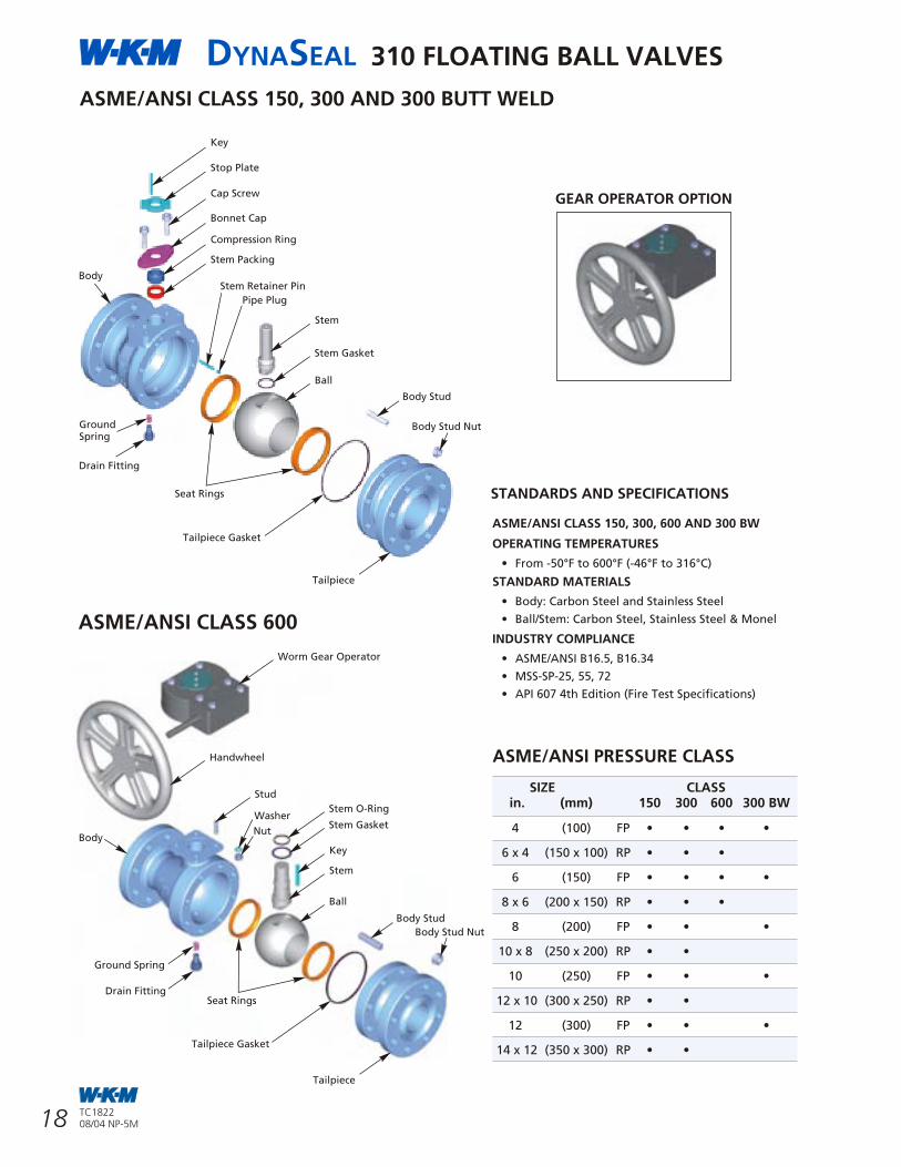
DYNASEAL 310 FLOATING BALL VALVES
15
DYNASEAL 310 FLOATING BALL VALVES
18 TC182208/04 NP-5M
TC182208/04 NP-5M
1/4 in. (8 mm) FULL PORT THROUGH 4 in. (100 mm) REDUCED PORTFLANGED, THREADED AND SOCKET WELD DIMENSIONS
* American National Thread in inches.
SIZE A B C D E F G H* J Q* R S T W Xin. THD 150 300 600 600RJ THD 150 300 600
1/4 FP 3.00 - - - - 0.38 - 0.69 - - - 1.4 2.8 4.3 #8-32 .26 DP 0.88 5/16-24 - 0.18 0.25 0.55 0.38
3/8 FP 3.25 - - - - 0.38 - 0.69 - - - 1.4 2.8 4.3 #8-32 .26 DP 0.88 5/16-24 - 0.18 0.25 0.55 0.38
1/2 RP 3.75 - - - - 0.38 - 0.69 - - - 1.4 2.8 4.3 #8-32 .26 DP 0.88 5/16-24 - 0.18 0.25 0.55 0.38
1/2 FP 4.00 - - - - 0.50 - 0.81 - - - 1.8 3.5 5.7 #10-24 .26 DP 1.00 7/16-20 - 0.26 0.34 0.72 0.38
3/4 FP 4.25 - - - - 0.75 - 1.06 - - - 1.9 3.5 5.7 #10-24 .26 DP 1.00 7/16-20 - 0.26 0.34 0.72 0.38
1 RP 4.50 - - - - 0.75 - 1.06 - - - 1.9 3.5 5.4 #10-24 .26 DP 1.00 7/16-20 - 0.26 0.34 0.72 0.38
1 FP 4.50 5.0 6.50 8.5 8.50 1.00 - 1.32 2.12 2.44 2.44 2.8 4.1 7.0 1/4-20 .39 DP 1.25 5/8-18 - 0.36 0.63 1.25 0.38
1 1/2 FP 5.25 6.5 7.50 9.5 9.50 1.50 - 1.81 2.50 3.06 3.06 3.7 5.0 9.5 5/16-18 .45 DP 1.50 3/4-16 - 0.45 0.81 1.50 0.38
2 RP 6.25 7.0 8.50 11.5 11.62 1.50 2.0 1.81 3.00 3.25 3.25 3.7 5.0 9.5 5/16-18 .45 DP 1.50 3/4-16 - 0.45 0.81 1.50 0.38
2 FP 6.25 7.0 8.50 11.5 11.62 2.00 - 2.38 3.00 3.25 3.25 5.0 5.4 15.0 1/2-13 .50 DP 2.44 - 1.12 0.69 1.37 1.88 0.38
3 x 2 RP 9.00 8.0 11.12 14.0 14.12 2.00 3.0 2.38 3.75 4.12 4.12 5.0 5.4 15.0 1/2-13 .50 DP 2.44 - 1.12 0.69 1.37 1.88 0.38
3 FP 10.00 8.0 11.12 14.0 14.12 3.44 - 3.28 3.75 4.12 4.12 6.4 7.1 15.0 1/2-13 .50 DP 3.00 - 1.12 0.74 1.75 2.31 0.38
4 RP 10.25 9.0 12.00 17.0 17.12 3.44 4.0 3.28 4.50 5.00 5.38 6.4 7.1 15.0 1/2-13 .50 DP 3.00 - 1.12 0.74 1.75 2.31 0.38
SIZE mm
6 FP 76 - - - - 10 - 18 - - - 35 70 108 #8-32 6.6 DP 22 5/16-24 - 5 6 14 10
10 FP 83 - - - - 10 - 18 - - - 35 70 108 #8-32 6.6 DP 22 5-16-24 - 5 6 14 10
15 RP 95 - - - - 10 13 18 - - - 35 70 108 #8-32 6.6 DP 22 5/16-24 - 5 6 14 10
15 FP 102 - - - - 13 - 20 - - - 45 89 145 #10-24 6.6 DP 25 7/16-20 - 7 9 18 10
20 FP 108 - - - - 19 - 27 - - - 48 89 145 #10-24 6.6 DP 25 7/16-20 - 7 9 18 10
25 RP 114 - - - - 19 25 27 - - - 48 89 137 #10-24 6.6 DP 25 7/16-20 - 7 9 18 10
25 FP 114 127 165 216 216 25 - 34 54 62 62 71 107 178 1/4-20 9.9 DP 32 5/8-18 - 9 16 31 10
40 FP 133 165 190 241 241 38 - 46 64 78 78 94 127 241 5/16-18 11.4 DP 38 3/4-16 - 11 21 38 10
50 RP 159 178 216 292 295 38 51 46 76 83 83 94 127 241 5/16-18 11.4 DP 38 3/4-16 - 11 21 38 10
50 FP 159 178 216 292 295 51 - 60 76 83 83 127 137 381 1/2-13 12.7 DP 62 - 28 18 35 48 10
80 x 50 RP 229 203 283 356 359 51 76 60 95 105 105 127 137 381 1/2-13 12.7 DP 62 - 28 18 35 48 10
80 FP 254 203 283 356 359 87 - 83 95 105 105 163 180 381 1/2-13 12.7 DP 76 - 28 19 44 59 10
100 RP 260 229 305 432 435 87 102 83 114 127 137 164 180 381 1/2-13 12.7 DP 76 - 28 19 44 59 10
SOCKET WELD END
SIZE in. A B C D E F G H J Q* S T W X
1/4 FP B103 7.00 0.38 1.41 0.62 1.41 2.84 4.25 #8-32 .25 DP 0.88 5/16-24 0.18 0.25 0.56 0.38
1/2 RP B106 7.88 0.38 1.41 0.62 1.41 2.84 4.25 #8-32 .25 DP 0.88 5/16-24 0.18 0.25 0.56 0.38
3/4 FP B103 8.25 0.75 1.94 1.00 1.94 3.75 5.75 #10-24 .25 DP 1.00 7/16-20 0.26 0.34 0.75 0.38
1 RP B106 8.25 0.75 1.94 1.00 1.94 3.75 5.75 #10-24 .25 DP 1.00 7/16-20 0.26 0.34 1.14 0.38
1 1/2 FP B103 9.25 1.50 3.56 1.75 3.56 5.00 9.50 5/16-18 .44 DP 1.50 3/4-16 0.45 0.81 1.34 0.38
2 RP B106 10.25 1.50 3.56 1.75 3.56 5.00 9.50 5/16-18 .44 DP 1.50 3/4-16 0.45 0.81 1.34 0.38
SIZE mm
8 FP B103 177.80 9.65 35.81 15.75 35.81 72.14 107.95 #8-32 6.4 DP 22.35 5/16-24 4.57 6.35 14.22 9.65
15 RP B106 200.15 9.65 35.81 15.75 35.81 72.14 107.95 #8-32 6.4 DP 22.35 5/16-24 4.57 6.35 14.22 9.65
20 FP B103 209.55 19.05 49.28 25.40 49.28 95.25 146.05 #10-24 6.4 DP 25.40 7/16-20 6.60 8.64 19.05 9.65
25 RP B106 209.55 19.05 49.28 25.40 49.28 95.25 146.05 #10-24 6.4 DP 25.40 7/16-20 6.60 8.64 28.96 9.65
40 FP B103 234.95 38.10 90.42 44.45 90.42 127.00 241.30 5/16-18 11.2 DP 38.10 3/4-16 11.43 20.57 34.04 9.65
50 RP B106 260.35 38.10 90.42 44.45 90.42 127.00 241.30 5/16-18 11.2 DP 38.10 3/4-16 11.43 20.57 34.04 9.65
ASME/ANSI PRESSURE CLASS
SIZE CLASS in. (mm) 150 300 600 300 BW
4 (100) FP • • • •
6 x 4 (150 x 100) RP • • •
6 (150) FP • • • •
8 x 6 (200 x 150) RP • • •
8 (200) FP • • •
10 x 8 (250 x 200) RP • •
10 (250) FP • • •
12 x 10 (300 x 250) RP • •
12 (300) FP • • •
14 x 12 (350 x 300) RP • •
STANDARDS AND SPECIFICATIONS
ASME/ANSI CLASS 150, 300 AND 300 BUTT WELD
ASME/ANSI CLASS 150, 300, 600 AND 300 BW
OPERATING TEMPERATURES
• From -50°F to 600°F (-46°F to 316°C)
STANDARD MATERIALS
• Body: Carbon Steel and Stainless Steel
• Ball/Stem: Carbon Steel, Stainless Steel & Monel
INDUSTRY COMPLIANCE
• ASME/ANSI B16.5, B16.34
• MSS-SP-25, 55, 72
• API 607 4th Edition (Fire Test Specifications)
Ball
GEAR OPERATOR OPTION
ASME/ANSI CLASS 600
Stem Gasket
Stem
Body Stud
Body Stud Nut
Tailpiece Gasket
Tailpiece
Stem Retainer Pin
Pipe Plug
Stem Packing
Compression Ring
Bonnet Cap
Cap Screw
Stop Plate
Key
Body
Ball
Stem Gasket
Stem
Body Stud
Body Stud Nut
Seat Rings
Tailpiece Gasket
Tailpiece
Stem O-Ring
Stud
Key
Washer
NutBody
Handwheel
Worm Gear Operator
Ground Spring
Drain Fitting
Seat Rings
THREADED AND FLANGED ENDS
GroundSpring
Drain Fitting
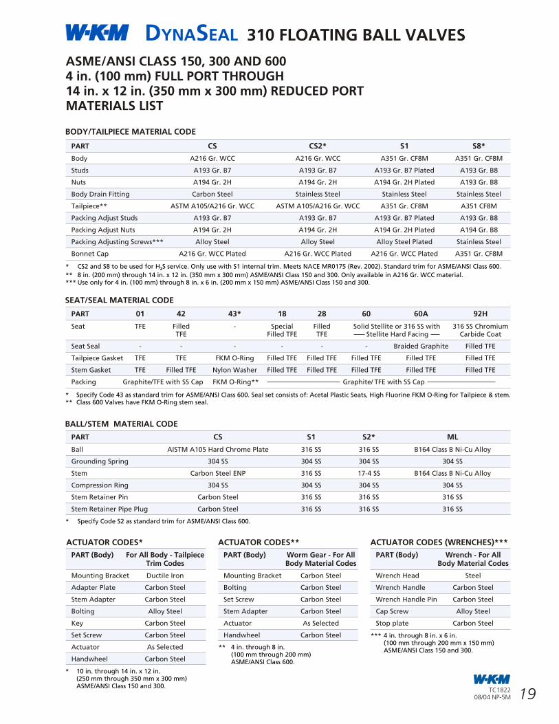
DYNASEAL 310 FLOATING BALL VALVES
14
DYNASEAL 310 FLOATING BALL VALVES
19TC182208/04 NP-5M
TC182208/04 NP-5M
A Approximate Dimensions in inchesSIZE 150 Flg 300 Flg 150 Flg 300 Flgin. B102 B122 B112 B130 B D E F G H* J Q* S T W X
1/2 FP - - 4.25 - 0.50 1.75 1.8 3.5 5.8 10-24 .38 DP 1.0 7/16-20 0.246 0.41 0.72 0.38- - - 5.50 0.50 1.88 1.8 3.5 5.8 10-24 .38 DP 1.0 7/16-20 0.246 0.41 0.72 0.38
3/4 RP 4.62 - - - 0.50 1.94 1.8 3.5 5.8 10-24 .31 DP 1.0 7/16-20 0.246 0.41 0.72 0.38- 6.00 - - 0.50 2.31 1.8 3.5 5.8 10-24 .31 DP 1.0 7/16-20 0.246 0.41 0.72 0.38
1 RP 5.00 - - - 0.75 2.13 2.3 4.0 6.7 10-24 .25 DP 1.0 7/16-20 0.246 0.48 0.84 0.38- 6.50 - - 0.75 2.44 2.3 4.0 6.7 10-24 .25 DP 1.0 7/16-20 0.246 0.48 0.84 0.38
SIZE mm Approximate Dimensions in millimeters
15 FP - - 108 - 13 44 46 89 147 10-24 9.7 DP 25 7/16-20 6 10 18 10- - - 140 13 48 46 89 147 10-24 9.7 DP 25 7/16-20 6 10 18 10
20 RP 117 - - - 13 49 46 89 147 10-24 7.9 DP 25 7/16-20 6 10 18 10- 152 - - 13 49 46 89 147 10-24 7.9 DP 25 7/16-20 6 10 18 10
25 RP 127 - - - 19 54 58 102 170 10-24 6.4 DP 25 7/16-20 6 12 21 10- 165 - - 19 54 58 102 170 10-24 6.4 DP 25 7/16-20 6 12 21 10
* American National Thread in inches.
UNIBODY VALVES - FLANGED ENDS
1/4 in. (8 mm) FULL PORT THROUGH 4 in. (100 mm) REDUCED PORTFLANGED, THREADED AND SOCKET WELDB136/B138 ThreadedB100/B110 Class150 Raised Face Flanges B120/B128 Class 300 Raised Face Flanges B114/B182 Class 600 Raised Face FlangesB170/B172 Class 600 Ring Joint Flanges B102/B112 Class150 Raised Face Flanges B122/B130 Class 300 Raised Face FlangesB106/B103 Socket Weld
BOREDIA
UNIBODYDESIGN
BODY/TAILPIECE MATERIAL CODE
PART CS CS2* S1 S8*
Body A216 Gr. WCC A216 Gr. WCC A351 Gr. CF8M A351 Gr. CF8M
Studs A193 Gr. B7 A193 Gr. B7 A193 Gr. B7 Plated A193 Gr. B8
Nuts A194 Gr. 2H A194 Gr. 2H A194 Gr. 2H Plated A193 Gr. B8
Body Drain Fitting Carbon Steel Stainless Steel Stainless Steel Stainless Steel
Tailpiece** ASTM A105/A216 Gr. WCC ASTM A105/A216 Gr. WCC A351 Gr. CF8M A351 CF8M
Packing Adjust Studs A193 Gr. B7 A193 Gr. B7 A193 Gr. B7 Plated A193 Gr. B8
Packing Adjust Nuts A194 Gr. 2H A194 Gr. 2H A194 Gr. 2H Plated A194 Gr. B8
Packing Adjusting Screws*** Alloy Steel Alloy Steel Alloy Steel Plated Stainless Steel
Bonnet Cap A216 Gr. WCC Plated A216 Gr. WCC Plated A216 Gr. WCC Plated A351 Gr. CF8M
* CS2 and S8 to be used for H S service. Only use with S1 internal trim. Meets NACE MR0175 (Rev. 2002). Standard trim for ASME/ANSI Class 600.2
** 8 in. (200 mm) through 14 in. x 12 in. (350 mm x 300 mm) ASME/ANSI Class 150 and 300. Only available in A216 Gr. WCC material.*** Use only for 4 in. (100 mm) through 8 in. x 6 in. (200 mm x 150 mm) ASME/ANSI Class 150 and 300.
ASME/ANSI CLASS 150, 300 AND 6004 in. (100 mm) FULL PORT THROUGH14 in. x 12 in. (350 mm x 300 mm) REDUCED PORTMATERIALS LIST
SEAT/SEAL MATERIAL CODE
PART 01 42 43* 18 28 60 60A 92H
Seat TFE Filled - Special Filled Solid Stellite or 316 SS with 316 SS ChromiumTFE Filled TFE TFE Stellite Hard Facing Carbide Coat
Seat Seal - - - - - - Braided Graphite Filled TFE
Tailpiece Gasket TFE TFE FKM O-Ring Filled TFE Filled TFE Filled TFE Filled TFE Filled TFE
Stem Gasket TFE Filled TFE Nylon Washer Filled TFE Filled TFE Filled TFE Filled TFE Filled TFE
Packing Graphite/TFE with SS Cap FKM O-Ring** Graphite/ TFE with SS Cap
BALL/STEM MATERIAL CODE
PART CS S1 S2* ML
Ball AISTM A105 Hard Chrome Plate 316 SS 316 SS B164 Class B Ni-Cu Alloy
Grounding Spring 304 SS 304 SS 304 SS 304 SS
Stem Carbon Steel ENP 316 SS 17-4 SS B164 Class B Ni-Cu Alloy
Compression Ring 304 SS 304 SS 304 SS 304 SS
Stem Retainer Pin Carbon Steel 316 SS 316 SS 316 SS
Stem Retainer Pipe Plug Carbon Steel 316 SS 316 SS 316 SS
* Specify Code 43 as standard trim for ASME/ANSI Class 600. Seal set consists of: Acetal Plastic Seats, High Fluorine FKM O-Ring for Tailpiece & stem.** Class 600 Valves have FKM O-Ring stem seal.
* Specify Code S2 as standard trim for ASME/ANSI Class 600.
ACTUATOR CODES*
PART (Body) For All Body - Tailpiece Trim Codes
Mounting Bracket Ductile Iron
Adapter Plate Carbon Steel
Stem Adapter Carbon Steel
Bolting Alloy Steel
Key Carbon Steel
Set Screw Carbon Steel
Actuator As Selected
Handwheel Carbon Steel
ACTUATOR CODES** ACTUATOR CODES (WRENCHES)***
* 10 in. through 14 in. x 12 in.(250 mm through 350 mm x 300 mm)ASME/ANSI Class 150 and 300.
** 4 in. through 8 in.(100 mm through 200 mm)ASME/ANSI Class 600.
*** 4 in. through 8 in. x 6 in.(100 mm through 200 mm x 150 mm)ASME/ANSI Class 150 and 300.
PART (Body) Worm Gear - For AllBody Material Codes
Mounting Bracket Carbon Steel
Bolting Carbon Steel
Set Screw Carbon Steel
Stem Adapter Carbon Steel
Actuator As Selected
Handwheel Carbon Steel
PART (Body) Wrench - For AllBody Material Codes
Wrench Head Steel
Wrench Handle Carbon Steel
Wrench Handle Pin Carbon Steel
Cap Screw Alloy Steel
Stop plate Carbon Steel
1 in. (25 mm) FULL PORT THROUGH2 in. (50 mm) REDUCED PORT
XJ
J
H
DIA
2 in. (50 mm) FULL PORT THROUGH4 in. (100 mm) REDUCED PORT
BOREDIA
1 in. (25 mm) REDUCED PORT AND SMALLER
DIABOREDIA
J
JH
G
G
A
F
E
D
W
C B
A
A
G
J
JH
X
G
W
E
D
A
B C
G
FW
E
B
A
C
D
E
D
BOREDIA
B
J
J
F
F
Q
S
T
STEMDIMENSIONS
Q
S
T
STEMDIMENSIONS
S
T
STEMDIMENSIONS
R
T
W
S
X
W
X
QSTEMDIMENSIONS
DIA
BOREDIA
B
H
FD
E
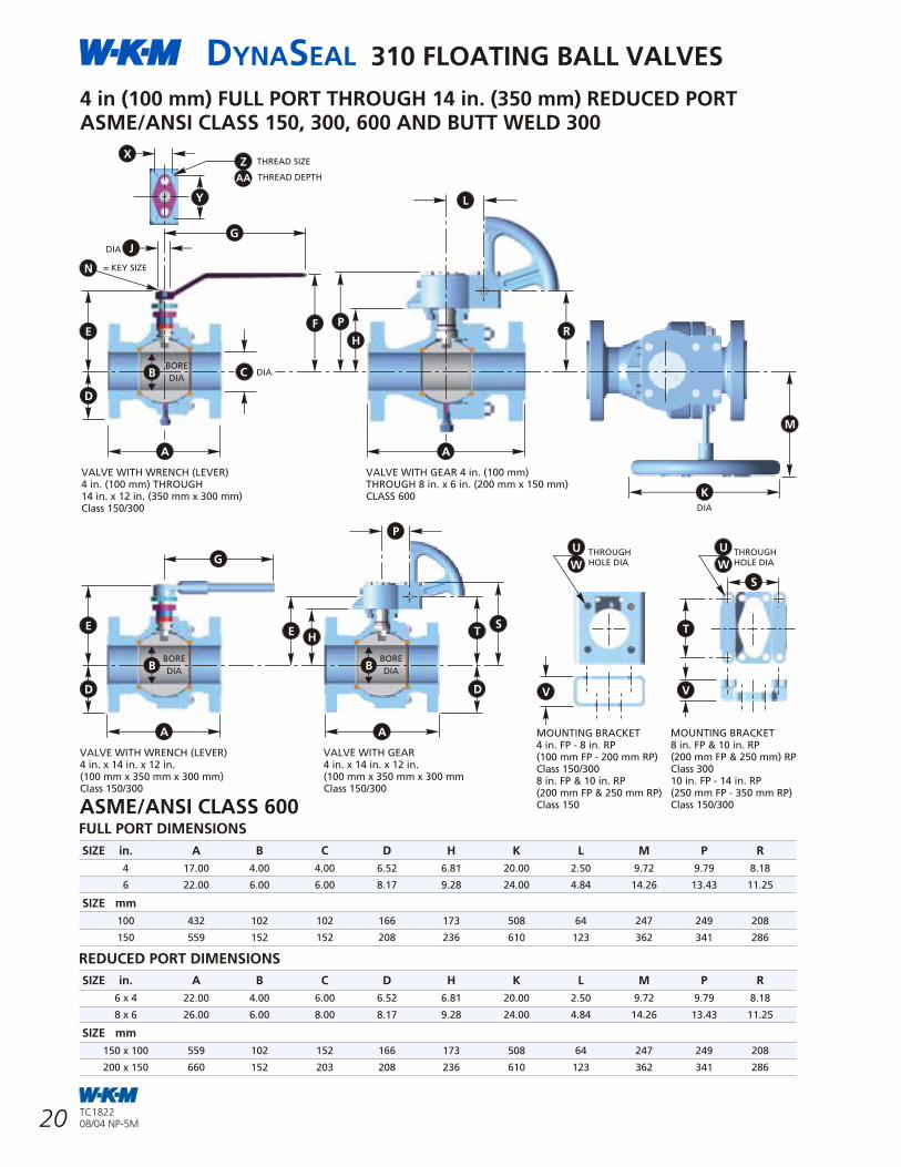
DYNASEAL 310 FLOATING BALL VALVES
13
DYNASEAL 310 FLOATING BALL VALVES
20 TC182208/04 NP-5M
TC182208/04 NP-5M
BODY/TAILPIECE MATERIAL CODE
PART CS CS2* CS3* S8*
Body ASTM A105/A216 Gr. WCC ASTM A105/A216 Gr. WCC ASTM A350 LF2 316 SS/A351 CF8M
Studs A193 Gr. B7 A193 Gr. B7M A320 Gr. L7M A193 Gr. B8
Nuts A194 Gr. 2H A194 Gr. 2HM A194 Gr. 7ML A194 Gr. 8
Body Plug** Carbon Steel Carbon Steel Carbon Steel Stainless Steel
Tailpiece ASTM A105/A216 Gr. WCC*** ASTM A105/A216 Gr. WCC ASTM A350 LF2 316 SS/A351 CF8M
Nameplate Stainless Steel Stainless Steel Stainless Steel Stainless Steel
Bonnet Cap Carbon Steel Carbon Steel Carbon Steel Stainless Steel
Packing Adjusting Screws Alloy Steel Plated 18-8 SS 18-8 SS 18-8 SS
1/4 in. (8 mm) FULL PORT THROUGH 4 in. (100 mm) REDUCED PORTMATERIALS LIST - THREADED AND FLANGED ENDS
SEAT SEAL MATERIAL CODE
PART 01 23** 42 43 48*** 07 18 60A* 92H*
Seat TFE Celcon Filled Acetal Acetal FKM Special Stellite 316 SS ChromiumTFE Plastic Plastic Filled TFE Carbide Coated
Tailpiece Gasket TFE TFE TFE TFE Filled TFE TFE Filled TFE Filled TFE Filled TFE
Stem Seal TFE Filled TFE
Packing Graphite/TFE w/SS Cap
BALL/STEM MATERIAL CODE
PART CS S1 S2* ML
Ball AISI 1213 CS Chrome Plate 316 SS 316SS B164 Class B Ni-Cu Alloy
Stem AISI 1213 Zinc Plate 316 SS 17-4 PH B 164 Class B Ni-Cu Alloy
Compression Ring 304 SS 304 SS 304 SS 304 SS
ACTUATOR CODE
PART (BODY) CS CS2 CS3 S1 S8
Lock Nut* Alloy Steel Alloy Steel Alloy Steel Alloy Steel Stainless Steel
Handle* CS Zinc Plated CS Zinc Plated CS Zinc Plated CS Zinc Plated Stainless Steel
Handle Grip* Vinyl Vinyl Vinyl Vinyl Vinyl
Wrench Handle** Ductile Iron Ductile Iron Ductile Iron Ductile Iron Ductile Iron
Wrench Head Bolt & Nut** Alloy Steel Alloy Steel Alloy Steel Alloy Steel Alloy Steel
Stop Plate Stainless Steel Stainless Steel Stainless Steel Stainless Steel Stainless Steel
* CS2/CS3/S8 to be used for H S service with S2 internal trim only. Meets NACE MR0175 (Rev. 2002).2
** When body drain is specified.
*** AISI 1018 Seat Retainers are used in 1/2 in., 3/4 in. and 1 x 3/4 in. (15 mm, 20 mm and 25 mm x 20 mm) Class 150 and 300 unibody valves.
* 1 inch (25 mm) Full Port and larger.** 1 inch (25 mm) Reduced Port and smaller.*** Socket Weld End valves only
Note: *S2 Trim (17-4 PH Stem & 316 SS Ball) is required for H S service per NACE MR0175 (Rev. 2002) to be used with Body/Tailpiece codes CS2/CS3/S8.2
* 2 inch (50 mm) Reduced Port and smaller.** 2 inch (50 mm) Full Port and larger.
4 in (100 mm) FULL PORT THROUGH 14 in. (350 mm) REDUCED PORTASME/ANSI CLASS 150, 300, 600 AND BUTT WELD 300
MOUNTING BRACKET4 in. FP - 8 in. RP(100 mm FP - 200 mm RP)Class 150/3008 in. FP & 10 in. RP(200 mm FP & 250 mm RP)Class 150
FULL PORT DIMENSIONS
SIZE in. A B C D H K L M P R
4 17.00 4.00 4.00 6.52 6.81 20.00 2.50 9.72 9.79 8.18
6 22.00 6.00 6.00 8.17 9.28 24.00 4.84 14.26 13.43 11.25
SIZE mm
100 432 102 102 166 173 508 64 247 249 208
150 559 152 152 208 236 610 123 362 341 286
REDUCED PORT DIMENSIONS
ASME/ANSI CLASS 600
SIZE in. A B C D H K L M P R
6 x 4 22.00 4.00 6.00 6.52 6.81 20.00 2.50 9.72 9.79 8.18
8 x 6 26.00 6.00 8.00 8.17 9.28 24.00 4.84 14.26 13.43 11.25
SIZE mm
150 x 100 559 102 152 166 173 508 64 247 249 208
200 x 150 660 152 203 208 236 610 123 362 341 286
VALVE WITH GEAR 4 in. (100 mm)THROUGH 8 in. x 6 in. (200 mm x 150 mm)CLASS 600
BORE
DIA
Z THREAD SIZE
D
F
DIA
DIA
B C
E
= KEY SIZE
HR
P
DIA
M
AA THREAD DEPTH
VALVE WITH WRENCH (LEVER)4 in. (100 mm) THROUGH14 in. x 12 in. (350 mm x 300 mm)Class 150/300
D
E
VALVE WITH WRENCH (LEVER)4 in. x 14 in. x 12 in.(100 mm x 350 mm x 300 mm)Class 150/300
BORE
DIAB
HE
BORE
DIAB
VALVE WITH GEAR4 in. x 14 in. x 12 in.(100 mm x 350 mm x 300 mmClass 150/300
V V
T
THROUGHHOLE DIA
THROUGHHOLE DIA
U
W
K
L
AA
N
J
G
X
Y
A A
G
P
S
ST
D
MOUNTING BRACKET8 in. FP & 10 in. RP (200 mm FP & 250 mm) RPClass 30010 in. FP - 14 in. RP(250 mm FP - 350 mm RP)Class 150/300
U
W
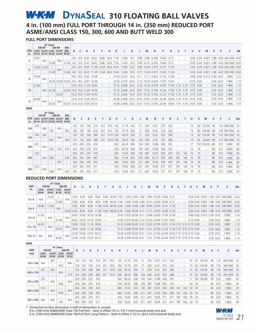
DYNASEAL 310 FLOATING BALL VALVES
12
DYNASEAL 310 FLOATING BALL VALVES
21TC182208/04 NP-5M
TC182208/04 NP-5M
STANDARDS AND SPECIFICATIONS
• To 5000 psi in small sizes
• Trim 43 pressure range to3000 psi in 1/4 in. (8 mm) to 3 in. x 2 in.(80 mm x 50 mm) Threaded End Valves
OPERATING TEMPERATURES
• From -50°F to 600°F (-46°C to 316°C)
STANDARD MATERIAL
Body:
• Carbon Steel and Stainless Steel
Ball/Stem:
• Carbon Steel, Stainless Steel and Monel
Seat/Seal Trims:
• TFE, Filled TFE, Acetal Plastic, HPT-2,316 Stainless Steel withChromium Carbide and FKM
INDUSTRY COMPLIANCE:
• ASME/ANSI B16.5, B16.34
• MSS-SP-6, 25, 55, 72
• API 607 4th Edition(Fire Test Specification)
FLANGED CONNECTIONSASME/ANSI PRESSURE CLASS
SIZE CLASS in. (mm) 150 300 600
1 (25) FP • • •
1 1/2 (40) FP • • •
2 x 1 1/2 (50 x 40) RP • • •
2 (50) FP • • •
3 x 2 (80 x 50) RP • • •
3 (80) FP • • •
4 x 3 (100 x 80) RP • • •
FLANGED ENDS
THREADED ENDS
THREADED CONNECTIONS
FULL PORT REDUCED PORTSIZE SIZE
in. (mm) in. (mm)
1/4 (8) 1/2 (15)
3/8 (10) 1 (25)
1/2 (15) 2 (50)
3/4 (20) 3 (80)
1 (25) 4 (100)
1 1/2 (40)
2 (50)
3 (80)
Lock Nut
Handle
Stop Plate
Bonnet Cap
Body
Tailpiece
Compression Ring
Packing
Stem Seal
Stem
Tailpiece Gasket
Seat Ring
Ball
Seat Ring
Cap Screws
Tailpiece
Body Stud Nut
Body Stud
Stem
Stem Seal
Packing
Compression Ring
Retainer Ring
Ball
Seat Ring
Seat Ring
Tailpiece Gasket
Bonnet Cap
Handle
Stop Plate
Bolt
Body
Cap Screws
* Centerline-to-face dimension is half of dimension A, except:4 in. (100 mm) ASME/ANSI Class 150 Full Port - stem is offset 1/2 in. (12.7 mm) towards body end and6 in. (150 mm) ASME/ANSI Class 150 Full Port Long Pattern - stem is offset 2 1/2 in. (63.5 mm) towards body end.
FULL PORT DIMENSIONS
4 in. (100 mm) FULL PORT THROUGH 14 in. (350 mm) REDUCED PORTASME/ANSI CLASS 150, 300, 600 AND BUTT WELD 300
REDUCED PORT DIMENSIONS
mm
mm
A* ClassSIZE 150 RF 300 RF B C D E F G H J K L M N P R S T U V W X Y Z AAin. LONG SHORT LONG SHORT
B100 B102 B120 B122
10.50 - 4.00 6.00 6.45 8.63 9.88 36.00 7.56 1.250 8.00 2.80 7.88 0.250 10.84 9.15 - - 0.56 2.44 4.921 1.88 4.63 3/8-16NC 0.636 x 4 N/A N/A
- 15.88 4.00 6.00 6.45 8.63 9.88 36.00 7.56 1.250 10.00 2.80 8.12 0.250 10.84 9.15 - - 0.56 2.44 4.921 1.88 4.63 3/8-16NC 0.63
18.00 11.50 - 6.00 8.00 8.20 11.38 12.63 48.00 9.44 1.500 14.00 2.80 10.95 0.375 12.72 11.03 - - 0.56 2.44 4.921 1.88 4.63 3/8-16NC 0.638 x 6 N/A
- - 16.50 6.00 8.00 8.20 11.38 12.63 48.00 9.44 1.500 16.00 4.11 11.11 0.375 13.28 11.33 - - 0.56 2.44 4.921 1.88 4.63 3/8-16NC 0.63
21.00 - 8.00 10.00 10.10 16.38 - - 13.50 2.375 20.00 4.11 13.64 0.625 17.34 15.39 - - 0.68 4.00 5.512 3.50 8.25 1-8NC 1.1310 x 8 N/A N/A
- 22.38 8.00 10.00 10.10 16.38 - - 12.50 2.375 20.00 5.12 15.25 0.625 17.07 14.67 - - 0.75 3.00 - 3.50 8.25 1-8NC 1.13
24.00 - 10.00 12.00 11.78 18.50 - - 15.12 2.938 24.00 5.12 15.25 0.750 19.70 17.30 7.75 5.75 0.75 3.00 - 3.50 8.25 1-8NC 1.1312 x 10 N/A N/A
- 25.50 10.00 12.00 11.78 18.50 - - 15.12 2.938 20.00 8.31 17.61 0.750 21.24 17.30 7.75 5.75 0.75 3.00 - 3.50 8.25 1-8NC 1.13
- 12.00 14.00 13.97 20.13 - - 16.38 2.938 20.00 8.31 17.61 0.750 22.49 18.55 7.75 5.75 0.75 3.00 - 3.50 8.25 1-8NC 1.1314 x 12 N/A N/A N/A
30.00 12.00 14.00 13.97 20.13 - - 16.38 2.938 24.00 8.31 17.61 0.750 22.49 18.55 7.75 5.75 0.75 3.00 - 3.50 8.25 1-8NC 1.13
A* ClassSIZE 150 RF 300 RF B C D E F G H J K L M N P R S T U V W X Y Z AA
LONG SHORT LONG SHORTmmB100 B102 B120 B122
267 - 102 152 164 219 251 914 192 31.75 203 71 200 6.35 275 232 - - 14 62 124.99 48 118 3/8-16NC 16150 x 100 N/A N/A
- 403 102 152 164 219 251 914 192 31.75 254 71 206 6.35 275 232 - - 14 62 124.99 48 118 3/8-16NC 16
457 292 - 152 203 208 289 321 1219 240 38.10 356 71 278 9.53 323 280 - - 14 62 124.99 48 118 3/8-16NC 16200 x 150 N/A
- - 419 152 203 208 289 321 1219 240 38.10 406 104 282 9.53 337 288 - - 14 62 124.99 48 118 3/8-16NC 16
533 - 203 254 257 416 - - 343 60.33 508 104 346 15.88 440 391 - - 17 102 140.00 89 210 1-8NC 29250 x 200 N/A N/A
- 568 203 254 257 416 - - 318 60.33 508 130 387 15.88 434 373 - - 19 76 - 89 210 1-8NC 29
610 - 254 305 299 470 - - 384 74.63 610 130 387 19.05 500 439 197 146 19 76 - 89 210 1-8NC 29300 x 250 N/A N/A
- 648 254 305 299 470 - - 384 74.63 508 211 447 19.05 539 439 197 146 19 76 - 89 210 1-8NC 29
- 305 356 355 511 - - 416 74.63 508 211 447 19.05 571 471 197 146 19 76 - 89 210 1-8NC 29350 x 300 N/A N/A N/A
762 305 356 355 511 - - 416 74.63 610 211 447 19.05 571 471 197 146 19 76 - 89 210 1-8NC 29
A* Class 150 RF 300 RF 300
SIZE LONG SHORT LONG SHORT BW B C D E F G H J K L M N P R S T U V W X Y Z AAin. B110 B113 B128 B134 B150
9.00 - - 4.0 4.0 6.47 8.63 9.88 36.0 7.56 1.250 8.0 2.80 7.88 0.250 10.84 9.15 - - 0.56 2.44 4.921 1.88 4.63 3/8-16NC 0.634 N/A N/A
- 12.00 12.00 4.0 4.0 6.47 8.63 9.88 36.0 7.56 1.250 10.0 2.80 8.12 0.250 10.84 9.15 - - 0.56 2.44 4.921 1.88 4.63 3/8-16NC 0.63
15.50 10.50 - - 6.0 6.0 8.20 11.38 12.63 48.0 9.44 1.500 14.0 2.80 10.95 0.375 12.72 11.03 - - 0.56 2.44 4.921 1.88 4.63 3/8-16NC 0.636 N/A
- - 15.88 15.88 6.0 6.0 8.20 11.38 12.63 48.0 9.44 1.500 14.0 4.11 13.24 0.375 13.28 11.33 - - 0.56 2.44 4.921 1.88 4.63 3/8-16NC 0.63
18.00 - - - 8.0 8.0 9.95 16.38 - - 13.50 2.375 16.0 4.11 11.11 0.625 17.34 15.39 - - 0.68 4.00 5.512 3.50 8.25 1-8NC 1.138 N/A
- 19.75 16.50 16.50 8.0 8.0 9.97 16.38 - - 12.50 2.375 20.0 5.12 15.25 0.625 17.07 14.67 - - 0.75 3.00 - 3.50 8.25 1-8NC 1.13
21.00 - - - 10.0 10.0 11.63 18.50 - - 15.12 2.938 20.0 5.12 15.25 0.750 19.70 17.30 7.75 5.75 0.75 3.00 - 3.50 8.25 1-8NC 1.13
10 - N/A 22.38 - 22.00 10.0 10.0 11.65 18.50 - - 15.12 2.938 20.0 8.31 17.61 0.750 21.24 17.30 7.75 5.75 0.75 3.00 - 3.50 8.25 1-8NC 1.13
- - 18.00 - 10.0 10.0 11.65 18.50 - - 15.12 2.938 16.0 8.31 15.32 0.750 21.24 17.30 7.75 5.75 0.75 3.00 - 3.50 8.25 1-8NC 1.13
3.50 8.25 1-8NC 1.1324.00 - - 12.0 12.0 13.97 20.13 - - 16.38 2.938 20.0 8.31 17.61 0.750 22.49 18.55 7.75 5.75 0.75 3.00 -12 N/A N/A
- 25.50 25.00 12.0 12.0 13.97 20.13 - - 16.38 2.938 24.0 8.31 17.61 0.750 22.49 18.55 7.75 5.75 0.75 3.00 - 3.50 8.25 1-8NC 1.13
A* Class 150 RF 300 RF 300
SIZE LONG SHORT LONG SHORT BW B C D E F G H J K L M N P R S T U V W X Y Z AAin. B110 B113 B128 B134 B150
229 - - 102 102 164 219 251 914 192 31.75 203 71 200 6.35 275 232 - - 14 62 124.99 48 118 3/8-16NC 16100 N/A N/A
- 305 305 102 102 164 219 251 914 192 31.75 254 71 206 6.35 275 232 - - 14 62 124.99 48 118 3/8-16NC 16
394 267 - - 152 152 208 289 321 1219 240 38.10 356 71 278 9.53 323 280 - - 14 62 124.99 48 118 3/8-16NC 16150 N/A
- - 403 403 152 152 208 289 321 1219 240 38.10 356 104 336 9.53 337 280 - - 14 62 124.99 48 118 3/8-16NC 16
457 - - - 203 203 253 416 - - 343 60.33 406 104 282 15.88 440 391 - - 17 102 140.00 89 210 1-8NC 29200 N/A
- 502 419 419 203 203 253 416 - - 318 60.33 508 130 387 15.88 434 373 - - 19 76 - 89 210 1-8NC 29
533 - - - 254 254 295 470 - - 384 74.63 508 130 387 19.05 500 439 197 146 19 76 - 89 210 1-8NC 29
250 - N/A 568 - 559 254 254 295 467 - - 382 77.45 504 212 444 22.75 535 439 197 146 19 76 - 89 210 1-8NC 29
- - 457 - 254 254 296 470 - - 384 74.63 406 211 389 19.05 539 439 197 146 19 76 - 89 210 1-8NC 29
610 - - 305 305 355 511 - - 416 74.63 508 211 447 19.05 571 471 197 146 19 76 - 89 210 1-8NC 29300 N/A N/A
- 648 635 305 305 355 511 - - 416 74.63 610 211 447 19.05 571 471 197 146 19 76 - 89 210 1-8NC 29
Lock Nut
Handle
Bonnet Cap
Cap Screw
Cap Screw
1/4 in. (8 mm) FULL PORT - 1 in. (25 mm) REDUCED PORT
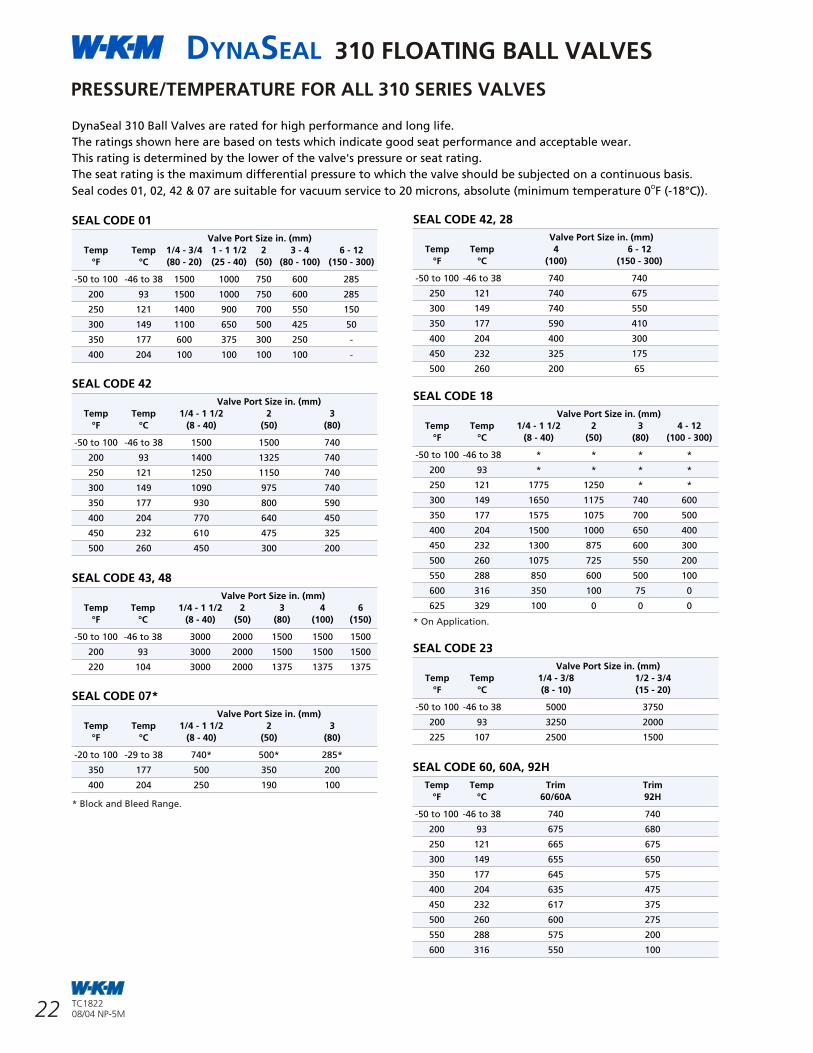
DYNASEAL 310 FLOATING BALL VALVES
11
DYNASEAL 310 FLOATING BALL VALVES
22 TC182208/04 NP-5M
TC182208/04 NP-5M
STANDARDS AND SPECIFICATIONS
Sizes:• 1/4 in. (8 mm) Full Port
• 1/2 in. (15 mm) Reduced Port
• 3/4 in. (20 mm) Full Port
• 1 in. (25 mm) Reduced Port
• 1 1/2 in. (40 mm) Full Port
• 2 in. (50 mm) Reduced Port.
WORKING PRESSURE • 3000 psi with Trim “48”
OPERATING TEMPERATURES• From -20°F to 220°F (-29°C to 104°C).
END CONNECTIONS• Socket Weld Ends.
STANDARD MATERIAL
Body:• Carbon Steel and
Carbon Steel NACE MR0175 (Rev. 2002).
Ball/Stem:• Carbon Steel or Stainless Steel.
Seats: • Trim “48”(Acetal Plastic Seats).
INDUSTRY STANDARDS COMPLIANCE• ASME/ANSI B16.34
• MSS-SP-25, 55, 72
• API 607 4th Edition (Fire Test).
SOCKET WELD ENDS
FLANGED ENDS - UNIBODY DESIGNSTANDARDS AND SPECIFICATIONS
Sizes:• 1/2 in. (15 mm) Full Port
• 3/4 in. x 1/2 in. (20 mm x 15 mm) Reduced Port
• 1 in. x 3/4 in. (25 mm x 20 mm) Reduced Port
PRESSURE CLASS • ASME/ANSI 150 & 300
STANDARD END CONNECTIONS• Flanged, Raised Face.
STANDARD MATERIAL
Body:• Carbon Steel, CF8M SS.
Ball/Stem:• Carbon Steel, 316 SS/17-4PH.
Seats:• Select from page 8.
OPTIONAL MATERIALS• Bodies, Stems & Balls can be offered in
different alloys - Consult Factory.
Seat Materials:• High Temp TFE, FKM, Stellite,
Chromium Carbide Coated, Acetal Plastic.
INDUSTRY STANDARDS COMPLIANCE• ASME/ANSI B16.34, B16.5.
• MSS-SP-6, 25, 55, 72.
• API 607 4th Edition (Fire Test).
Lock Nut
Tailpiece
Tailpiece Gasket
Handle
Compression Ring
Packing
Stem seal
Stem
Ball
Bonnet Cap
Seat Ring
Body
Seat Ring
Tailpiece Gasket
Tailpiece
Handle
Body
Cap Screw
Stem
Stem Seal
Packing
Ball
Seat Ring
Tailpiece Gasket
Body Plug
Lock Nut
Seat Ring
Stop Plate Cap Screw
Cap Screw
Cap Screw
PRESSURE/TEMPERATURE FOR ALL 310 SERIES VALVES
DynaSeal 310 Ball Valves are rated for high performance and long life.
The ratings shown here are based on tests which indicate good seat performance and acceptable wear.
This rating is determined by the lower of the valve's pressure or seat rating.
The seat rating is the maximum differential pressure to which the valve should be subjected on a continuous basis.OSeal codes 01, 02, 42 & 07 are suitable for vacuum service to 20 microns, absolute (minimum temperature 0 F (-18°C)).
SEAL CODE 01
Valve Port Size in. (mm)
Temp Temp 1/4 - 3/4 1 - 1 1/2 2 3 - 4 6 - 12
°F °C (80 - 20) (25 - 40) (50) (80 - 100) (150 - 300)
-50 to 100 -46 to 38 1500 1000 750 600 285
200 93 1500 1000 750 600 285
250 121 1400 900 700 550 150
300 149 1100 650 500 425 50
350 177 600 375 300 250 -
400 204 100 100 100 100 -
SEAL CODE 42
Valve Port Size in. (mm)
Temp Temp 1/4 - 1 1/2 2 3
°F °C (8 - 40) (50) (80)
-50 to 100 -46 to 38 1500 1500 740
200 93 1400 1325 740
250 121 1250 1150 740
300 149 1090 975 740
350 177 930 800 590
400 204 770 640 450
450 232 610 475 325
500 260 450 300 200
SEAL CODE 43, 48
Valve Port Size in. (mm)
Temp Temp 1/4 - 1 1/2 2 3 4 6
°F °C (8 - 40) (50) (80) (100) (150)
-50 to 100 -46 to 38 3000 2000 1500 1500 1500
200 93 3000 2000 1500 1500 1500
220 104 3000 2000 1375 1375 1375
SEAL CODE 07*
Valve Port Size in. (mm)
Temp Temp 1/4 - 1 1/2 2 3
°F °C (8 - 40) (50) (80)
-20 to 100 -29 to 38 740* 500* 285*
350 177 500 350 200
400 204 250 190 100
* Block and Bleed Range.
SEAL CODE 42, 28
Valve Port Size in. (mm)
Temp Temp 4 6 - 12
°F °C (100) (150 - 300)
-50 to 100 -46 to 38 740 740
250 121 740 675
300 149 740 550
350 177 590 410
400 204 400 300
450 232 325 175
500 260 200 65
SEAL CODE 18
Valve Port Size in. (mm)
Temp Temp 1/4 - 1 1/2 2 3 4 - 12
°F °C (8 - 40) (50) (80) (100 - 300)
-50 to 100 -46 to 38 * * * *
200 93 * * * *
250 121 1775 1250 * *
300 149 1650 1175 740 600
350 177 1575 1075 700 500
400 204 1500 1000 650 400
450 232 1300 875 600 300
500 260 1075 725 550 200
550 288 850 600 500 100
600 316 350 100 75 0
625 329 100 0 0 0
* On Application.
SEAL CODE 23
Valve Port Size in. (mm)
Temp Temp 1/4 - 3/8 1/2 - 3/4
°F °C (8 - 10) (15 - 20)
-50 to 100 -46 to 38 5000 3750
200 93 3250 2000
225 107 2500 1500
SEAL CODE 60, 60A, 92H
Temp Temp Trim Trim
°F °C 60/60A 92H
-50 to 100 -46 to 38 740 740
200 93 675 680
250 121 665 675
300 149 655 650
350 177 645 575
400 204 635 475
450 232 617 375
500 260 600 275
550 288 575 200
600 316 550 100
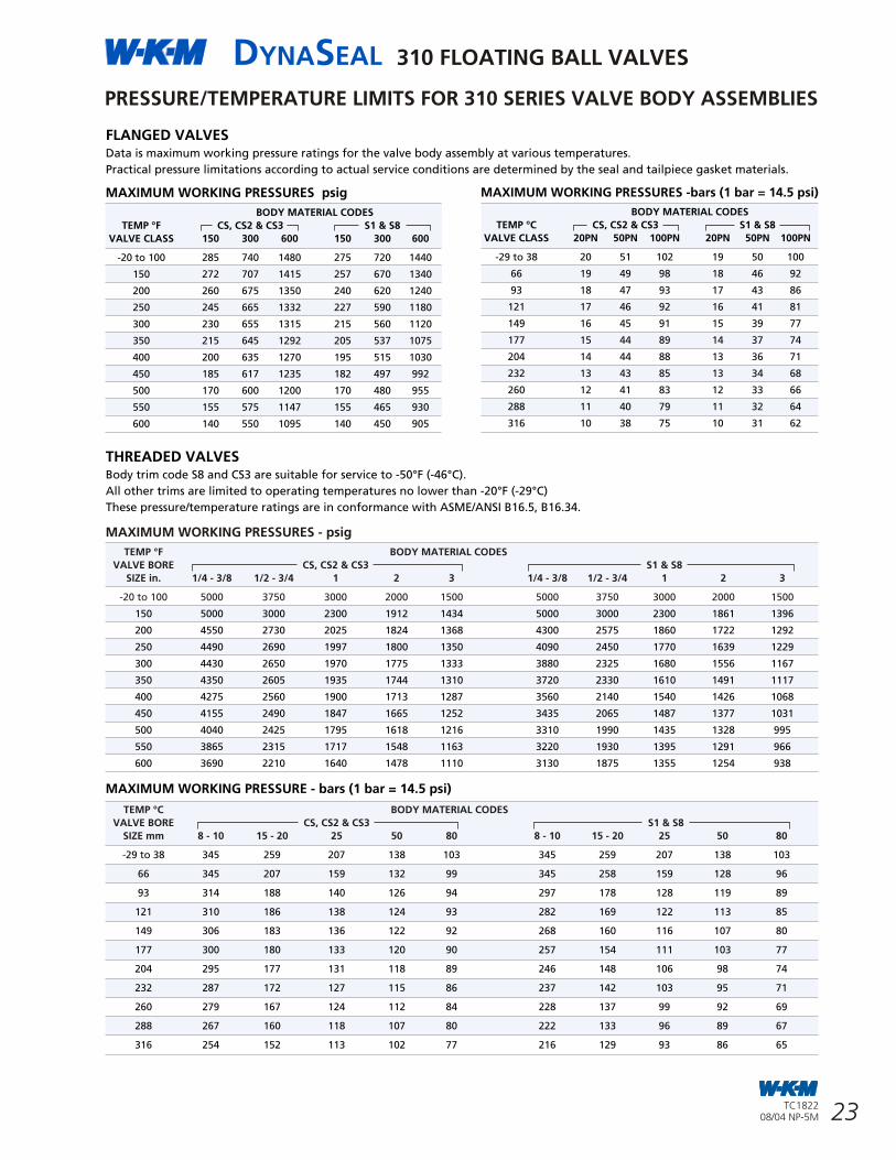
DYNASEAL 310 FLOATING BALL VALVES
10
DYNASEAL 310 FLOATING BALL VALVES
23TC182208/04 NP-5M
TC182208/04 NP-5M
W-K-M DynaSeal 310 floating ball valves satisfy a wide range of applications. Available in a variety of standard and optional materials, in sizes from1/4 in. (8 mm) to 4 in. x 3 in.(100 mm x 80 mm) and working pressures to 5000 psi. Engineered for heavy duty, maintenance free performance, the DynaSeal 310 valve is preferred for use in critical applications.
SOUR OIL AND GAS SERVICEDynaSeal ball valves have served for years in gathering lines, manifolds and field processing units in sour oil and gas fields. They can be trimmed to conform with NACE MR0175 (Rev. 2002).
DEEP RECESSED SEATS The DynaSeal 310 seat is protected in a machined recess or deep pocket that surrounds and protects the seat. This design eliminates cold flow into the valve conduit and avoids potential seat damage from ball movement or flow media.
TRIM 42 SEATSSeats are manufactured of filled TFE and rated to 1500 psi MOP. With working temperatures to 500°F (260°C) and low torque operation these seats satisfy even the most difficult of processing requirements.
TRIM 43 SEATS Seats are manufactured of Acetal Plastic and rated to 3000 psi MOP and working temperatures to 220°F (104°C). These seats are designed to handle the most demanding applications. These seats are designed to flex under pressure and provide a consistent range of low torque operations. They provide a full face seal against the ball and multiple seals against the top and back of the pocket to provide a positive seal.
ADJUSTABLE, REPLACEABLE PACKINGThe in line valve stem packing consists of PTFE impregnated graphite with an impervious metal barrier and a secondary tapered metal back up. The packing is field adjustable and never requires lubrication. The packing and the stainless steel cap can be replaced without removing the valve from the line.
POSITIVELY RETAINED STEM The stem is positively retained with a shoulder. It cannot be removed with the valve in service. There are no O-rings used in this design.
FEATURES AND BENEFITS
310 Unibody1/2 in., 3/4 in. x 1/2 & 1 in. x 3/4 in.(15 mm, 20 mm x 15 mm and25 mm x 20 mm) Class 150 & 300 Flanged.
Socket Weld End310 Ball Valve
PRESSUREHERE
FLOATING BALL DESIGN DELIVERS TIGHT SEAL The ground and polished ball is free to float and mates perfectly with the conical seats for a positive, leakproof seal. Self cleaning and self adjusting, the ball is also pressure activated - the higher the line pressure, the tighter the seal.
FIRE-TESTED FOR SAFETYAll DynaSeal 310 valves are qualified under API standard 607 4th Edition. The pocketed seat and locked in stem design contributes to its excellent firetested characteristics. Should the soft seats be destroyed by fire, the ball floats down stream, providing a tight metal to metal seal against the lip of the seat pocket. If the tailpiece seals are destroyed, the metal to metaltailpiece to body connection retards external leakage.
TRIM 42 SEAT
INDICATOR HANDLEThe design of the handle permits installation on the stem in the correct position only, in alignment with the ball port. When the handle is aligned with the pipe, the valve is open.When the handle is perpendicular to the pipe, the valve is closed.
LOCKING DEVICES Locking devices are standard on all4 in. x 3 in. (100 mm x 80 mm) and smaller manually operated valves and permit locking in either the open or closed positions.
PRESSURE/TEMPERATURE LIMITS FOR 310 SERIES VALVE BODY ASSEMBLIES
FLANGED VALVESData is maximum working pressure ratings for the valve body assembly at various temperatures.
Practical pressure limitations according to actual service conditions are determined by the seal and tailpiece gasket materials.
THREADED VALVESBody trim code S8 and CS3 are suitable for service to -50°F (-46°C).
All other trims are limited to operating temperatures no lower than -20°F (-29°C)
These pressure/temperature ratings are in conformance with ASME/ANSI B16.5, B16.34.
MAXIMUM WORKING PRESSURES psig
BODY MATERIAL CODES
TEMP °F CS, CS2 & CS3 S1 & S8
VALVE CLASS 150 300 600 150 300 600
-20 to 100 285 740 1480 275 720 1440
150 272 707 1415 257 670 1340
200 260 675 1350 240 620 1240
250 245 665 1332 227 590 1180
300 230 655 1315 215 560 1120
350 215 645 1292 205 537 1075
400 200 635 1270 195 515 1030
450 185 617 1235 182 497 992
500 170 600 1200 170 480 955
550 155 575 1147 155 465 930
600 140 550 1095 140 450 905
MAXIMUM WORKING PRESSURES -bars (1 bar = 14.5 psi)
BODY MATERIAL CODES
TEMP °C CS, CS2 & CS3 S1 & S8
VALVE CLASS 20PN 50PN 100PN 20PN 50PN 100PN
-29 to 38 20 51 102 19 50 100
66 19 49 98 18 46 92
93 18 47 93 17 43 86
121 17 46 92 16 41 81
149 16 45 91 15 39 77
177 15 44 89 14 37 74
204 14 44 88 13 36 71
232 13 43 85 13 34 68
260 12 41 83 12 33 66
288 11 40 79 11 32 64
316 10 38 75 10 31 62
MAXIMUM WORKING PRESSURES - psig
TEMP °F BODY MATERIAL CODES
VALVE BORE CS, CS2 & CS3 S1 & S8
SIZE in. 1/4 - 3/8 1/2 - 3/4 1 2 3 1/4 - 3/8 1/2 - 3/4 1 2 3
-20 to 100 5000 3750 3000 2000 1500 5000 3750 3000 2000 1500
TEMP °C BODY MATERIAL CODES
VALVE BORE CS, CS2 & CS3 S1 & S8
SIZE mm 8 - 10 15 - 20 25 50 80 8 - 10 15 - 20 25 50 80
150 5000 3000 2300 1912 1434 5000 3000 2300 1861 1396
200 4550 2730 2025 1824 1368 4300 2575 1860 1722 1292
250 4490 2690 1997 1800 1350 4090 2450 1770 1639 1229
300 4430 2650 1970 1775 1333 3880 2325 1680 1556 1167
350 4350 2605 1935 1744 1310 3720 2330 1610 1491 1117
400 4275 2560 1900 1713 1287 3560 2140 1540 1426 1068
450 4155 2490 1847 1665 1252 3435 2065 1487 1377 1031
500 4040 2425 1795 1618 1216 3310 1990 1435 1328 995
550 3865 2315 1717 1548 1163 3220 1930 1395 1291 966
600 3690 2210 1640 1478 1110 3130 1875 1355 1254 938
MAXIMUM WORKING PRESSURE - bars (1 bar = 14.5 psi)
-29 to 38 345 259 207 138 103 345 259 207 138 103
66 345 207 159 132 99 345 258 159 128 96
93 314 188 140 126 94 297 178 128 119 89
121 310 186 138 124 93 282 169 122 113 85
149 306 183 136 122 92 268 160 116 107 80
177 300 180 133 120 90 257 154 111 103 77
204 295 177 131 118 89 246 148 106 98 74
232 287 172 127 115 86 237 142 103 95 71
260 279 167 124 112 84 228 137 99 92 69
288 267 160 118 107 80 222 133 96 89 67
316 254 152 113 102 77 216 129 93 86 65
TRIM 43 SEAT
METAL TO METAL SEAL
ADJUSTABLE PACKING
CONICAL SEAT
METAL SHOULDER
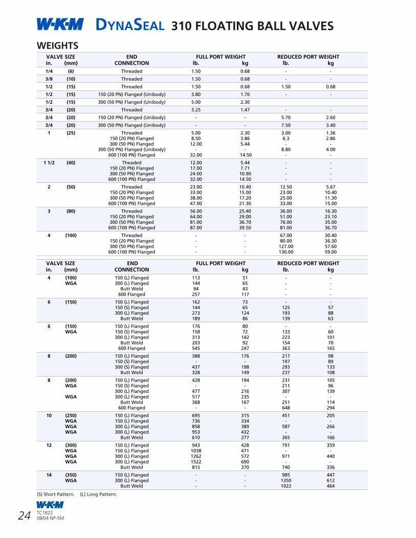
DYNASEAL 310 FLOATING BALL VALVES
9
DYNASEAL 310 FLOATING BALL VALVES
24 TC182208/04 NP-5M
TC182208/04 NP-5M
A premium quality floating ball valve that has proven itself in a wide variety of oilfield, chemical, petrochemical and hydrocarbon processing applications.
FEATURES AND BENEFITS
THREADED VALVE ASSEMBLY1/4 in. (8 mm) FULL PORTTHROUGH4 in. x 3 in. (100 mm x 80 mm)REDUCED PORT.
FLANGED VALVE ASSEMBLY1 in. (25 mm) FULL PORTTHROUGH4 in. x 3 in. (100 mm x 80 mm)REDUCED PORT.
Packing can bereplaced withoutremoving valvefrom line.
Handle providespositive indication ofopen/closed position.
Seat is in deep protective pocket whichprevents cold flow of seat into line
Stem is positivelyretained, cannotbe removed withvalve in service.
Floating ball is selfadjusting, self cleaning.
Packing can bereplaced withoutremoving valvefrom line.
Floating ball isself adjusting,self cleaning.
Seat is in deep protectivepocket which preventscold flow of seat into line.
Stem is positively retained,cannot be removed withvalve in service.
Open or closed positionlocking plateallows use of popularpadlock designs.
2 piece bolted bodyAPI 607 4th Editionfire tested.
2 piece threaded bodyAPI 607 4th Editionfire tested.
Open or closed positionlocking plate allows use ofpopular padlock designs.
WEIGHTS VALVE SIZE END FULL PORT WEIGHT REDUCED PORT WEIGHT
in. (mm) CONNECTION lb. kg lb. kg
1/4 (6) Threaded 1.50 0.68 - -
3/8 (10) Threaded 1.50 0.68 - -
1/2 (15) Threaded 1.50 0.68 1.50 0.68
1/2 (15) 150 (20 PN) Flanged (Unibody) 3.80 1.70 - -
1/2 (15) 300 (50 PN) Flanged (Unibody) 5.00 2.30
3/4 (20) Threaded 3.25 1.47 - -
3/4 (20) 150 (20 PN) Flanged (Unibody) - - 5.70 2.60
3/4 (20) 300 (50 PN) Flanged (Unibody) - - 7.50 3.40
1 (25) Threaded 5.00 2.30 3.00 1.36150 (20 PN) Flanged 8.50 3.86 6.3 2.86300 (50 PN) Flanged 12.00 5.44 - -
300 (50 PN) Flanged (Unibody) - - 8.80 4.00600 (100 PN) Flanged 32.00 14.50 - -
1 1/2 (40) Theaded 12.00 5.44 - -150 (20 PN) Flanged 17.00 7.71 - -300 (50 PN) Flanged 24.00 10.90 - -600 (100 PN) Flanged 32.00 14.50 - -
2 (50) Threaded 23.00 10.40 12.50 5.67150 (20 PN) Flanged 33.00 15.00 23.00 10.40300 (50 PN) Flanged 38.00 17.20 25.00 11.30
600 (100 PN) Flanged 47.00 21.30 33.00 15.00
3 (80) Threaded 56.00 25.40 36.00 16.30150 (20 PN) Flanged 64.00 29.00 51.00 23.10300 (50 PN) Flanged 81.00 36.70 76.00 35.00
600 (100 PN) Flanged 87.00 39.50 81.00 36.70
4 (100) Threaded - - 67.00 30.40150 (20 PN) Flanged - - 80.00 36.30300 (50 PN) Flanged - - 127.00 57.60
600 (100 PN) Flanged - - 130.00 59.00
VALVE SIZE END FULL PORT WEIGHT REDUCED PORT WEIGHTin. (mm) CONNECTION lb. kg lb. kg
4 (100) 150 (L) Flanged 113 51 - -WGA 300 (L) Flanged 144 65 - -
Butt Weld 94 43 - -600 Flanged 257 117 - -
6 (150) 150 (L) Flanged 162 73 - -150 (S) Flanged 144 65 125 57300 (L) Flanged 273 124 193 88
Butt Weld 189 86 139 63
6 (150) 150 (L) Flanged 176 80 - -WGA 150 (S) Flanged 158 72 133 60
300 (L) Flanged 313 142 223 101Butt Weld 203 92 154 70
600 Flanged 545 247 363 165
8 (200) 150 (L) Flanged 388 176 217 98150 (S) Flanged - - 197 89300 (S) Flanged 437 198 293 133
Butt Weld 328 149 237 108
8 (200) 150 (L) Flanged 428 194 231 105WGA 150 (S) Flanged - - 211 96
300 (L) Flanged 477 216 307 139WGA 300 (L) Flanged 517 235 - -
Butt Weld 368 167 251 114600 Flanged - - 648 294
10 (250) 150 (L) Flanged 695 315 451 205WGA 150 (L) Flanged 736 334 - -WGA 300 (L) Flanged 858 389 587 266WGA 300 (L) Flanged 953 432 - -
Butt Weld 610 277 365 166
12 (300) 150 (L) Flanged 943 428 791 359WGA 150 (L) Flanged 1038 471 - -WGA 300 (L) Flanged 1262 572 971 440WGA 300 (L) Flanged 1522 690 - -
Butt Weld 815 370 740 336
14 (350) 150 (L) Flanged - - 985 447WGA 300 (L) Flanged - - 1350 612
Butt Weld - - 1022 464
(S) Short Pattern. (L) Long Pattern.
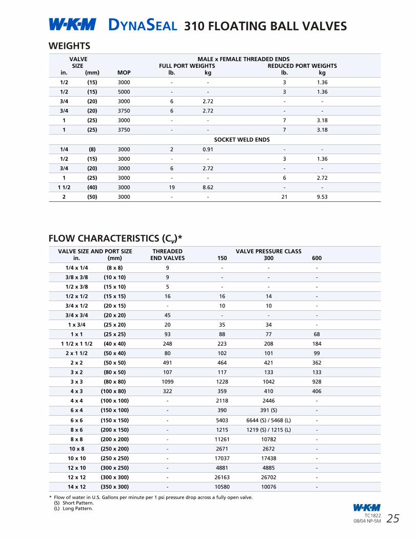
DYNASEAL 310 FLOATING BALL VALVES
8
DYNASEAL 310 FLOATING BALL VALVES
25TC182208/04 NP-5M
TC182208/04 NP-5M
TRIM GUIDELINES FOR ALL 310 SERIES VALVES
SEAL SEAT TAILPIECE SERVICECODE MATERIAL GASKET APPLICATION
01 TFE TFE Seat and Tailpiece gaskets are of virgin TFE. Use where lading contamination from glass or other fillers is not desirable, such as in food service. Recommended for low temperature service to -50°F (-46°C).Also recommended for vacuum service.
42 Filled TFE TFE Seat material is TFE filled with inert materials for use at elevated temperatures and pressures.Same chemical resistance as Virgin TFE except slightly affected by hot concentrated alkaline solutions.Some chlorinated compounds can cause swelling. Also recommended for low temperature service -50°F (-46°C).Good for vacuum service.
43 Homopolymer TFE For general use at high pressures to temperature of 220°F (104°C).Acetal Plastic
48 Homopolymer Filled TFE For general use at high pressures to temperature of 220°F (104°C).Acetal Plasic Used on socket weld end valves 3 in. (80 mm) bore size and smaller.
07 *FKM/ SS TFE High and low pressure block and bleed.General use for low pressure and abrasion resistance.Not suitable for steam. Good for vacuum service.Available in bore sizes to 3 in. (80 mm).
18 HPT-2 Filled TFE HPT-2 is a special TFE formulation for use at temperatures above trim 42 capability.Best suited for constant temperature or constant pressure applications.Proven service in steam, hot oil, heat transfer fluids, hot resins, boilerfeed water. Same chemical resistance as TFE.Slightly affected by hot, concentrated alkaline solutions.Some fluorinated compounds cause swelling.
23 Celcon TFE For use in high pressure applications.Temperature limited to 225°F (107°C) (1/4 in. to 3/4 in. (8 mm to 20 mm) bores only).
28 Filled TFE Filled TFE Same as 42 except tailpiece gasket is filled TFE.Used on weld end valves 4 in. (100 mm) and larger.
60 Stellite Filled TFE Special Stellite seats for digester blow down service, spent liquor and steam applications common to the pulp and paper industry.Leakage Class V.
60A Stellite Filled TFE Special Stellite seats for use when hard faced metal seats are required for applications outside the pulp and paper industry.Leakage Class V.
92H 316 SS with Filled TFE For temperatures to 600°F (316°C).Chrome Carbide For slurries, abrasives, steam, hot water.and Filled TFE Leakage Class V.
Note 1: Trim 07 and 18 should be tested for each application by actual use.
Note 2: All seal codes with the exception of 07, 60, 60A and 92H have been fire tested (and qualified) to API 607 4th Edition requirements.* Trim sizes smaller than 1 1/2 in. (40 mm) in trim 07 are 100% elastomeric. Sizes 1 1/2 in. (40 mm) and larger are elastomeric with a metal insert.
This chart is an abbreviated guide to the chemical resistance and pressure/temperature limitationsof the seal materials used in the 310 valve series.
Consult your DynaSeal distributor or the W-K-M factory regarding questions about trim selections.
* Flow of water in U.S. Gallons per minute per 1 psi pressure drop across a fully open valve.(S) Short Pattern.(L) Long Pattern.
FLOW CHARACTERISTICS (C )*VV
WEIGHTS
VALVE MALE x FEMALE THREADED ENDSSIZE FULL PORT WEIGHTS REDUCED PORT WEIGHTS
in. (mm) MOP lb. kg lb. kg
1/2 (15) 3000 - - 3 1.36
1/2 (15) 5000 - - 3 1.36
3/4 (20) 3000 6 2.72 - -
3/4 (20) 3750 6 2.72 - -
1 (25) 3000 - - 7 3.18
1 (25) 3750 - - 7 3.18
SOCKET WELD ENDS
1/4 (8) 3000 2 0.91 - -
1/2 (15) 3000 - - 3 1.36
3/4 (20) 3000 6 2.72 - -
1 (25) 3000 - - 6 2.72
1 1/2 (40) 3000 19 8.62 - -
2 (50) 3000 - - 21 9.53
VALVE SIZE AND PORT SIZE THREADED VALVE PRESSURE CLASSin. (mm) END VALVES 150 300 600
1/4 x 1/4 (8 x 8) 9 - - -
3/8 x 3/8 (10 x 10) 9 - - -
1/2 x 3/8 (15 x 10) 5 - - -
1/2 x 1/2 (15 x 15) 16 16 14 -
3/4 x 1/2 (20 x 15) - 10 10 -
3/4 x 3/4 (20 x 20) 45 - - -
1 x 3/4 (25 x 20) 20 35 34 -
1 x 1 (25 x 25) 93 88 77 68
1 1/2 x 1 1/2 (40 x 40) 248 223 208 184
2 x 1 1/2 (50 x 40) 80 102 101 99
2 x 2 (50 x 50) 491 464 421 362
3 x 2 (80 x 50) 107 117 133 133
3 x 3 (80 x 80) 1099 1228 1042 928
4 x 3 (100 x 80) 322 359 410 406
4 x 4 (100 x 100) - 2118 2446 -
6 x 4 (150 x 100) - 390 391 (S) -
6 x 6 (150 x 150) - 5403 6644 (S) / 5468 (L) -
8 x 6 (200 x 150) - 1215 1219 (S) / 1215 (L) -
8 x 8 (200 x 200) - 11261 10782 -
10 x 8 (250 x 200) - 2671 2672 -
10 x 10 (250 x 250) - 17037 17438 -
12 x 10 (300 x 250) - 4881 4885 -
12 x 12 (300 x 300) - 26163 26702 -
14 x 12 (350 x 300) - 10580 10076 -
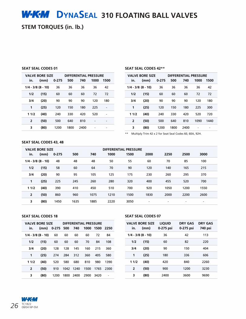
7
DYNASEAL 310 FLOATING BALL VALVES
26 TC182208/04 NP-5M
TC182208/04 NP-5M
DYNASEAL 310 FLOATING BALL VALVES
HOW TO ORDER
Seal Seal Tailpiece Gasket Number Material Material
01 PTFE PTFE
42 Filled PTFE PTFE
43 Homopolymer Acetal Plastic PTFE
07 FKM PTFE
18 HPT-2 Filled PTFE
23 Celcon PTFE
28 Filled PTFE Filled PTFE
48 Homopolymer Acetal Plastic Filled PTFE
60 Stellite Filled PTFE
60A Stellite Filled PTFE
92H 316 SS with Chrome Carbide & Filled PTFE Filled PTFE
2 R B 1 3 6 C S 4 3 S 2 W R
Size Port Valve Body Seal Ball & Actuatorinches Reduced Port = R Type Tailpiece Code Stem Code
Full Port = F Code Code
Materials Code
Carbon Steel CS
316 Stainless Steel S1
Ni-Cu Alloy ML
17-4PH S2*
Material Codes
Carbon Steel CS
Controlled hardness carbon steel for H S service CS2*2Same as CS2, but special for -50°F (-46°C) service CS3*
316 stainless steel for wetted parts S1
316 stainless steel with stainless steelexternal trim. Good for -50°F (-46°C). S8*
* Meets NACE *MR0175 (Rev. 2002)
* NACE 4 in. (100 mm) RP and smaller. 17-4 PH Stem, 316 Stainless Steel Ball.
Actuator Code
Wrench* WR
Oval Handwheel OH
Worm Gear WG
Bare Stem BS
Less Gear LG
Less Wrench LW
* Wrenches are part of the valve assemblyin 1 1/2 in. (40 mm) bore size and smaller valves. In 2 in. (50 mm) bore size andlarger, they are sold separately.
310 2-PIECE VALVE TYPES
SIZE 150 RF 300 RF 300 BW 600 RF 600 RJin. (mm) LP* SP* LP* SP* Butt Weld
**1/2 (15) FP B112 - B130 - - - -
** 3/4 (20) RP B102 - B122 - - - -
** 1 (25) RP B102 - B122 - - - -
1 (25) FP B110 - B128 - - B182 B172
1 1/2 (40) FP B110 - B128 - - B182 B172
2 (50) RP B100 - B120 - - B114 B170
2 (50) FP B110 - B128 - - B182 B172
3 x 2 (80 x 50) RP B100 - B120 - - B114 B170
3 (80) FP B110 - B128 - - B182 B172
4 (100) RP B100 - B120 - - B114 B170
4 (100) FP B110 - B128 - B150 B182*** B172***
6 (150) RP - B102 B120 - - B114*** B170***
6 (150) FP B110 B113 B128 - B150 B182*** B172***
8 (200) RP B100 B102 - B122 - B114*** B170***
8 (200) FP B110 - B128 B134 B150 - -
10 (300) RP B100 - B120 - - - -
10 (300) FP B110 - B128 B134 B150 - -
12 (300) RP B100 - B120 - - - -
12 (300) FP B110 - B128 - B150 - -
14 (350) RP B100 - B120 - - - -
310 2-PIECE VALVE TYPES
SIZE in. (mm) Female Thread Male x Female
1/4 (8) FP B138 -
3/8 (20) FP B138 -
1/2 (15) RP B136 B136 (M x F)**
1/2 (15) FP B138 -
3/4 (20) FP B138 B138 (M x F)**
1 (25) RP B136 B136 (M x F)**
1 (25) FP B138
1 1/2 (40) FP B138
2 (50) RP B136
2 (50) FP B138
3 (80) FP B138
4 (100) RP B136
** Available in Body Tailpiece Code S8 Only.Note: Threaded end valves have NPT internal pipe thread in full conformance with ASME/ANSI B2.1 andFederal Thread Handbook H-28.
* LP is Long Pattern, SP is Short Pattern.** Unibody style valve.*** The 4 in. (100 mm) and larger sizes are available in trim CS2-43-S2-WGA
(Worm Gear Operated) only.
310 3-PIECE VALVE TYPES
SIZE in. (mm) SOCKET WELD
1/4 (8) FP B103
3/8 (10) FP -
1/2 (15) RP B106
3/4 (20) FP B103
1 (25) RP B106
1 1/2 (40) FP B103
2 (50) RP B106
STEM TORQUES (in. lb.)
SEAT SEAL CODES 01
VALVE BORE SIZE DIFFERENTIAL PRESSURE
in. (mm) 0-275 500 740 1000 1500
1/4 - 3/8 (8 - 10) 36 36 36 36 42
1/2 (15) 60 60 60 72 72
3/4 (20) 90 90 90 120 180
1 (25) 120 150 180 225 -
1 1/2 (40) 240 330 420 520 -
2 (50) 500 640 810 - -
3 (80) 1200 1800 2400 - -
SEAT SEAL CODES 43, 48
VALVE BORE SIZE DIFFERENTIAL PRESSURE
in. (mm) 0-275 500 740 1000 1500 2000 2250 2500 3000
1/4 - 3/8 (8 - 10) 48 48 48 50 55 60 70 85 100
1/2 (15) 58 60 64 70 90 120 140 165 215
3/4 (20) 90 95 105 125 175 230 260 295 370
1 (25) 225 245 260 280 320 400 455 520 700
1 1/2 (40) 390 410 450 510 700 920 1050 1200 1550
2 (50) 860 960 1075 1210 1500 1830 2000 2200 2600
3 (80) 1450 1635 1885 2220 3050 - - - -
SEAT SEAL CODES 18
VALVE BORE SIZE DIFFERENTIAL PRESSURE
in. (mm) 0-275 500 740 1000 1500 2250
1/4 - 3/8 (8 - 10) 60 60 60 60 72 84
1/2 (15) 60 60 60 70 84 108
3/4 (20) 128 128 145 160 215 360
1 (25) 274 284 312 360 405 580
1 1/2 (40) 520 580 680 810 980 1390
2 (50) 910 1042 1240 1500 1765 2300
3 (80) 1200 1800 2400 2900 3420 -
SEAT SEAL CODES 42**
VALVE BORE SIZE DIFFERENTIAL PRESSURE
in. (mm) 0-275 500 740 1000 1500
1/4 - 3/8 (8 - 10) 36 36 36 36 42
1/2 (15) 60 60 60 72 72
3/4 (20) 90 90 90 120 180
1 (25) 120 150 180 225 300
1 1/2 (40) 240 330 420 520 720
2 (50) 500 640 810 1090 1440
3 (80) 1200 1800 2400 - -
SEAT SEAL CODES 07
VALVE BORE SIZE LIQUID DRY GAS DRY GAS
in. (mm) 0-275 psi 0-275 psi 740 psi
1/4 - 3/8 (8 - 10) 36 42 113
1/2 (15) 60 82 220
3/4 (20) 90 150 404
1 (25) 180 336 606
1 1/2 (40) 420 840 2260
2 (50) 900 1200 3230
3 (80) 2400 3600 9690
** Multiply Trim 42 x 2 for Seat Seal Codes 60, 60A, 92H.
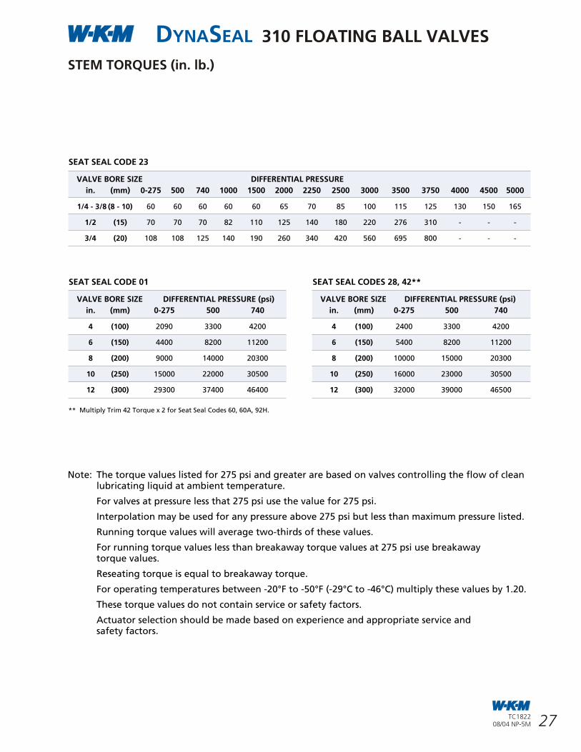
6 27
DYNASEAL 310 FLOATING BALL VALVES
TC182208/04 NP-5M
TC182208/04 NP-5M
DYNASEAL 210 FLOATING BALL VALVESDIMENSIONS AND WEIGHTS
FULL PORT (FP) REDUCED PORT (RP)
DIMENSIONAL DATA
SIZE DIMENSION A APPROXIMATE DIMENSIONS in inchesin. THREADED GROOVED B C E F G
1 FP 4.00 - 1.00 1.00 2.77 4.0 7.1
2 RP 5.55 5.25 1.50 2.00 3.56 4.9 7.1
2 FP 6.00 - 2.00 2.00 4.50 4.9 15.0
2 1/2 RP 7.00 - 2.00 2.50 4.50 4.9 15.0
3 RP 7.25 7.25 2.00 3.00 4.50 4.9 15.0
3 FP 8.75 - 3.00 3.00 5.66 6.0 15.0
4 RP 8.75 8.88 3.00 4.00 5.66 6.0 15.0
SIZE mm APPROXIMATE DIMENSIONS in millimeters
25 FP 102 - 25 25 70 102 180
50 RP 141 133 38 50 90 124 180
50 FP 152 - 51 50 114 124 381
65 RP 178 - 51 65 114 124 381
80 RP 184 184 51 80 114 124 381
80 FP 222 - 76 80 144 152 381
100 RP 222 226 76 100 144 152 381
WEIGHTS FULL PORT
WEIGHTS REDUCED PORTVALVE SIZE in. WEIGHT lb.
OPERATION 2 x 1 1/2 2 1/2 x 2 3 x 2 4 x 3
Without Handle lb. 9.4 15.5 16.6 35.5
With handle lb. 9.9 18.0 19.8 38.7
VALVE SIZE mm WEIGHT kg
OPERATION 50 x 40 65 x 50 80 x 50 100 x 80
Without Handle kg 4.3 7.0 7.5 16.1
With handle kg 4.5 8.2 9.0 17.6
VALVE SIZE in. WEIGHT lb.
OPERATION 1 x 1 2 x 2 3 x 3
Without Handle lb. 4.0 14.4 42.8
With handle lb. 4.5 17.6 46.0
VALVE SIZE mm WEIGHT kg
OPERATION 25 x 25 50 x 50 80 x 80
Without Handle kg 1.8 6.5 19.4
With handle kg 2.0 8.0 20.9
PIPE
A
E
B BOREDIAB
BOREDIA
F
C
A
G G
STEM TORQUES (in. lb.)
SEAT SEAL CODE 23
VALVE BORE SIZE DIFFERENTIAL PRESSURE
in. (mm) 0-275 500 740 1000 1500 2000 2250 2500 3000 3500 3750 4000 4500 5000
1/4 - 3/8 (8 - 10) 60 60 60 60 60 65 70 85 100 115 125 130 150 165
1/2 (15) 70 70 70 82 110 125 140 180 220 276 310 - - -
3/4 (20) 108 108 125 140 190 260 340 420 560 695 800 - - -
Note: The torque values listed for 275 psi and greater are based on valves controlling the flow of clean lubricating liquid at ambient temperature.
For valves at pressure less that 275 psi use the value for 275 psi.
Interpolation may be used for any pressure above 275 psi but less than maximum pressure listed.
Running torque values will average two-thirds of these values.
For running torque values less than breakaway torque values at 275 psi use breakawaytorque values.
Reseating torque is equal to breakaway torque.
For operating temperatures between -20°F to -50°F (-29°C to -46°C) multiply these values by 1.20.
These torque values do not contain service or safety factors.
Actuator selection should be made based on experience and appropriate service andsafety factors.
SEAT SEAL CODE 01
VALVE BORE SIZE DIFFERENTIAL PRESSURE (psi)
in. (mm) 0-275 500 740
4 (100) 2090 3300 4200
6 (150) 4400 8200 11200
8 (200) 9000 14000 20300
10 (250) 15000 22000 30500
12 (300) 29300 37400 46400
** Multiply Trim 42 Torque x 2 for Seat Seal Codes 60, 60A, 92H.
SEAT SEAL CODES 28, 42**
VALVE BORE SIZE DIFFERENTIAL PRESSURE (psi)
in. (mm) 0-275 500 740
4 (100) 2400 3300 4200
6 (150) 5400 8200 11200
8 (200) 10000 15000 20300
10 (250) 16000 23000 30500
12 (300) 32000 39000 46500
F
E
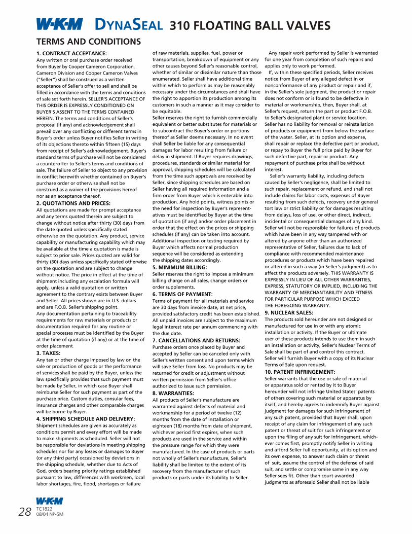
5
DYNASEAL 310 FLOATING BALL VALVESTERMS AND CONDITIONS1. CONTRACT ACCEPTANCE: Any written or oral purchase order received
from Buyer by Cooper Cameron Corporation,
Cameron Division and Cooper Cameron Valves
("Seller”) shall be construed as a written
acceptance of Seller's offer to sell and shall be
filled in accordance with the terms and conditions
of sale set forth herein. SELLER'S ACCEPTANCE OF
THIS ORDER IS EXPRESSLY CONDITIONED ON
BUYER'S ASSENT TO THE TERMS CONTAINED
HEREIN. The terms and conditions of Seller's
proposal (if any) and acknowledgement shall
prevail over any conflicting or different terms in
Buyer's order unless Buyer notifies Seller in writing
of its objections thereto within fifteen (15) days
from receipt of Seller's acknowledgement. Buyer's
standard terms of purchase will not be considered
a counteroffer to Seller's terms and conditions of
sale. The failure of Seller to object to any provision
in conflict herewith whether contained on Buyer's
purchase order or otherwise shall not be
construed as a waiver of the provisions hereof
nor as an acceptance thereof.
2. QUOTATIONS AND PRICES: All quotations are made for prompt acceptance
and any terms quoted therein are subject to
change without notice after thirty (30) days from
the date quoted unless specifically stated
otherwise on the quotation. Any product, service
capability or manufacturing capability which may
be available at the time a quotation is made is
subject to prior sale. Prices quoted are valid for
thirty (30) days unless specifically stated otherwise
on the quotation and are subject to change
without notice. The price in effect at the time of
shipment including any escalation formula will
apply, unless a valid quotation or written
agreement to the contrary exists between Buyer
and Seller. All prices shown are in U.S. dollars
and are F.O.B. Seller‘s shipping point.
Any documentation pertaining to traceability
requirements for raw materials or products or
documentation required for any routine or
special processes must be identified by the Buyer
at the time of quotation (if any) or at the time of
order placement.
3. TAXES: Any tax or other charge imposed by law on the
sale or production of goods or the performance
of services shall be paid by the Buyer, unless the
law specifically provides that such payment must
be made by Seller, in which case Buyer shall
reimburse Seller for such payment as part of the
purchase price. Custom duties, consular fees,
insurance charges and other comparable charges
will be borne by Buyer.
4. SHIPPING SCHEDULE AND DELIVERY: Shipment schedules are given as accurately as
conditions permit and every effort will be made
to make shipments as scheduled. Seller will not
be responsible for deviations in meeting shipping
schedules nor for any losses or damages to Buyer
(or any third party) occasioned by deviations in
the shipping schedule, whether due to Acts of
God, orders bearing priority ratings established
pursuant to law, differences with workmen, local
labor shortages, fire, flood, shortages or failure
of raw materials, supplies, fuel, power or
transportation, breakdown of equipment or any
other causes beyond Seller's reasonable control,
whether of similar or dissimilar nature than those
enumerated. Seller shall have additional time
within which to perform as may be reasonably
necessary under the circumstances and shall have
the right to apportion its production among its
customers in such a manner as it may consider to
be equitable.
Seller reserves the right to furnish commercially
equivalent or better substitutes for materials or
to subcontract the Buyer's order or portions
thereof as Seller deems necessary. In no event
shall Seller be liable for any consequential
damages for labor resulting from failure or
delay in shipment. If Buyer requires drawings,
procedures, standards or similar material for
approval, shipping schedules will be calculated
from the time such approvals are received by
Seller, since shipping schedules are based on
Seller having all required information and a
firm order from Buyer which is enterable into
production. Any hold points, witness points or
the need for inspection by Buyer's represent-
atives must be identified by Buyer at the time
of quotation (if any) and/or order placement in
order that the effect on the prices or shipping
schedules (if any) can be taken into account.
Additional inspection or testing required by
Buyer which affects normal production
sequence will be considered as extending
the shipping dates accordingly.
5. MINIMUM BILLING: Seller reserves the right to impose a minimum
billing charge on all sales, change orders or
order supplements.
6. TERMS OF PAYMENT: Terms of payment for all materials and service
are 30 days from invoice date, at net price,
provided satisfactory credit has been established.
All unpaid invoices are subject to the maximum
legal interest rate per annum commencing with
the due date.
7. CANCELLATIONS AND RETURNS: Purchase orders once placed by Buyer and
accepted by Seller can be canceled only with
Seller's written consent and upon terms which
will save Seller from loss. No products may be
returned for credit or adjustment without
written permission from Seller's office
authorized to issue such permission.
8. WARRANTIES: All products of Seller's manufacture are
warranted against defects of material and
workmanship for a period of twelve (12)
months from the date of installation or
eighteen (18) months from date of shipment,
whichever period first expires, when such
products are used in the service and within
the pressure range for which they were
manufactured. In the case of products or parts
not wholly of Seller's manufacture, Seller's
liability shall be limited to the extent of its
recovery from the manufacturer of such
products or parts under its liability to Seller.
Any repair work performed by Seller is warranted
for one year from completion of such repairs and
applies only to work performed.
If, within these specified periods, Seller receives
notice from Buyer of any alleged defect in or
nonconformance of any product or repair and if,
in the Seller's sole judgment, the product or repair
does not conform or is found to be defective in
material or workmanship, then, Buyer shall, at
Seller's request, return the part or product F.O.B.
to Seller's designated plant or service location.
Seller has no liability for removal or reinstallation
of products or equipment from below the surface
of the water. Seller, at its option and expense,
shall repair or replace the defective part or product,
or repay to Buyer the full price paid by Buyer for
such defective part, repair or product. Any
repayment of purchase price shall be without
interest.
Seller's warranty liability, including defects
caused by Seller's negligence, shall be limited to
such repair, replacement or refund, and shall not
include claims for labor costs, expenses of Buyer
resulting from such defects, recovery under general
tort law or strict liability or for damages resulting
from delays, loss of use, or other direct, indirect,
incidental or consequential damages of any kind.
Seller will not be responsible for failures of products
which have been in any way tampered with or
altered by anyone other than an authorized
representative of Seller, failures due to lack of
compliance with recommended maintenance
procedures or products which have been repaired
or altered in such a way (in Seller's judgment) as to
affect the products adversely. THIS WARRANTY IS
EXPRESSLY IN LIEU OF ALL OTHER WARRANTIES,
EXPRESS, STATUTORY OR IMPLIED, INCLUDING THE
WARRANTY OF MERCHANTABILITY AND FITNESS
FOR PARTICULAR PURPOSE WHICH EXCEED
THE FOREGOING WARRANTY.
9. NUCLEAR SALES: The products sold hereunder are not designed or
manufactured for use in or with any atomic
installation or activity. If the Buyer or ultimate
user of these products intends to use them in such
an installation or activity, Seller's Nuclear Terms of
Sale shall be part of and control this contract.
Seller will furnish Buyer with a copy of its Nuclear
Terms of Sale upon request.
10. PATENT INFRINGEMENT: Seller warrants that the use or sale of material
or apparatus sold or rented by it to Buyer
hereunder will not infringe United States' patents
of others covering such material or apparatus by
itself, and hereby agrees to indemnify Buyer against
judgment for damages for such infringement of
any such patent, provided that Buyer shall, upon
receipt of any claim for infringement of any such
patent or threat of suit for such infringement or
upon the filing of any suit for infringement, which-
ever comes first, promptly notify Seller in writing
and afford Seller full opportunity, at its option and
its own expense, to answer such claim or threat
of suit, assume the control of the defense of said
suit, and settle or compromise same in any way
Seller sees fit. Other than court-awarded
judgments as aforesaid Seller shall not be liable
28 TC182208/04 NP-5M
TC182208/04 NP-5M
DYNASEAL 210 FLOATING BALL VALVES
750, 1000, 1500 and 2000 psig WORKING PRESSURE1 in. (25 mm) FULL PORT THROUGH4 in. x 3 in. (100 mm x 80 mm) REDUCED PORT
STANDARD MATERIALS
Qty. DESCRIPTION MATERIAL
1 Body ASTM A395 Ductile Iron
1 Tailpiece ASTM A395 Ductile Iron
1 Ball Carbon Steel Chrome Plated316 SS
1 Stem AISI 1213/ 1215, Steel, Zinc Plated 316 SS (17-4PH SS on 2 in. x 1 1/2 in. (50 mm x 40 mm)
2 Seat Ring Acetal Plastic (43)Filled TFE (42)Carbon Filled TFE (2) 750/1000 psi
1 Tailpiece Gasket PTFE
2 Stem O-Ring Buna-NFKM
1 Stem Gasket (Thrust Bearing) Filled TFE
1 Locking Plate Steel 1018/ 26
1 Locking Plate Retaining Ring Spring Steel
1 Wave Spring Spring Steel
1 Stop Pin Spring Steel
1 Handle 1 in. (25 mm ) FP & 2 in. x 1 1/2 in. (50 x 40): Carbon Steel, Zinc Plated 2 in. (50 mm) FP through 4 in. x 3 in. (100 x 80): ASTM A395 Ductile Iron
1 Handle Retainer Nut on 1 in. (25 mm)Retainer Ring on 2 in. x 1 1/2 in. (50 mm x 40 mm)Bolt on 2 in. (50 mm) FP through 4 in. x 3 in. (100mm x 80 mm)
1 Seal Pin/Dart Brass or Aluminum
Note:For H S service use Trim Code -X13220X. Meets NACE MR0175 (Rev. 2002) (see “How To Order” page 1).2
4
for any delays, loss of use or for other direct,
indirect, incidental or consequential damages
incurred by reason of any such judgment. Seller
does not warrant that such material or
apparatus (a) will not infringe any such patent
when not manufactured by or for Seller or when
specially made in whole or in part to the Buyer's
design specification and such infringement arises
from the inclusion of such specified design or (b),
if used or sold in combination with other
material or apparatus, or if used in the practice
of a process, will not, as a result of such
combination or use, infringe any patent covering
such combination or process; and Seller shall not
be liable for and does not indemnify Buyer for
damages or losses of any nature whatsoever
resulting from actual or alleged patent
infringement arising pursuant to (a) or (b)
above.
11. SELLER'S RIGHT TO MANUFACTURE: Seller in its sole discretion shall have the right
to manufacture the products provided
hereunder as far in advance of its estimated
shipping schedule as it deems appropriate. Seller
expressly reserves the right to change or modify
the design and construction of any product in
due course of Seller's manufacturing procedure
without incurring any obligation or liability to
furnish or install such changes, modifications or
improvements to products previously or
subsequently sold.
12. ENGINEERING AND SERVICE: Upon request, Seller will provide engineering
and/or technical information regarding its
products and their uses and if feasible, will
provide personnel to assist Buyer in effecting
field installations and/or field service. Any such
information, service or assistance so provided,
whether with or without charge, shall be
advisory only. In that regard, neither Seller nor
Buyer assumes any liability for the acts or
omissions of the other party except as may be
provided in these terms.
13. LABOR STANDARDS: Seller hereby certifies that these products were
produced in accordance with all applicable
requirements of Section 6, 7 and 12 of the
Fair Labor Standards Act as amended and of
regulations and orders of the United States
Department of Labor issued under Section 14
thereof.
14. INSPECTION: Unless otherwise agreed in writing, final
inspection and acceptance of products must be
made at Seller's plant or other shipping or
receiving point designated by Seller and shall
be conclusive except as regards latent defects.
Buyer's representatives may inspect at the
Seller's plant or shipping point during working
hours prior to shipment in such manner as will
not interfere with operations.
15. DELIVERY AND ACCEPTANCE: Delivery shall be in accordance with the
requirements in the Purchase Contract, provided,
in the event Buyer is unable to accept delivery
upon completion of the manufacture of the
Goods in accordance with such requirements,
Buyer agrees that (i) title and risk of ownership
shall pass to Buyer on date of Seller's invoice and
(ii) Buyer will make payments within thirty days
after date of such invoice. Seller shall retain
custodial risk of loss until delivery is made in
accordance with such requirements.
16. TRANSPORTATION CHARGES, ALLOWANCES, CLAIMS:
All prices are F.O.B. Seller's plant or other
designated shipping point.
No freight is allowed unless stated in Seller's
quotation (if any) or in a written contract which
may exist between Seller and Buyer at the time
of shipment. If Seller's quotation or a written
contract states that all or a portion of freight is
allowed, all prices are F.O.B. Seller's plant or
other designated shipping point, with most
economical surface transportation allowed. If
the quoted or contractual price includes
transportation, Seller reserves the right to
designate the common carrier and to ship in the
manner it deems most economical. Added costs
due to special routing requested by the Buyer
are chargeable to the Buyer. Under no
circumstances is any freight allowance which is
absorbed by Seller to be deducted from the
selling price. If the quoted price or contract
includes transportation, no deduction will be
made in lieu thereof whether Buyer accepts
shipment at plant, warehouse, freight station,
or otherwise supplies its own transportation.
When sales are made from the Seller's
warehouse, Seller reserves the right to charge
either actual or pro-rated freight from Seller's
principle point of manufacture to Seller's
warehouse. Buyer assumes risk of loss upon
delivery to the carrier, regardless of who pays
shipping costs.
Seller endeavors to pack or prepare all
shipments so that they will not break, rust or
deteriorate in transit, but does not guarantee
against such damage. Unless requested in
writing by the Buyer, no shipments are insured
by Seller against damage or loss in transit. Seller
will place insurance as nearly as possible in
accordance with Buyer's written instructions but
in such case Seller acts only as agent between
the insurance company and the Buyer and
assumes no liability whatsoever.
Any claims for shipping loss, breakage or
damage (obvious or concealed) are Buyer's
responsibility and should be made to the carrier.
All claims regarding shortages must be made
within thirty (30) days from receipt of shipment
and must be accompanied by the packing list(s)
covering the shipment.
17. CONSULAR INVOICES: Consular fees for legalizing invoices, stamping
bills of lading, or other documents required
by the laws of any country or destination are
not included in quotations or selling prices.
If instructed in writing, Seller will make
arrangements for consular documents and
declarations as agent of the Buyer, but Seller
assumes no liability whatsoever as a result of
making such arrangements. Seller assumes no
responsibility for any fines or other charges
imposed due to errors or incorrect declarations.
CAM/T&C/US/96 REV. 9/03
18. INDEMNIFICATION AND LIMITATION OF LIABILITY: A. INDEMNIFICATION:
Seller agrees to indemnify Buyer and hold Buyer
harmless against any claims, demands or causes
of action for property damage or personal injury
(including death) caused by the negligent act or
omission of any employee, agent or sub-
contractor of Seller and not contributed to by
the negligence of Buyer, its employees, its agents
or any third party. Seller shall not be responsible
for the acts and workmanship of employees,
agents, contractors or subcontractors of Buyer
or any third party, nor for failure or malfunction
of any tools, materials, equipment, products,
supplies, facilities or devices not manufactured
and supplied by Seller. Buyer agrees to hold
Seller harmless from any and all losses, claims,
or damages arising from subsurface damage,
surface damage caused by subsurface damage,
loss of hydrocarbons and from pollution,
regardless of whether such damages, losses or
claims were caused by the negligence or sole
negligence of Seller, it being the intent of the
parties that this indemnity shall apply to
property of Buyer or to that of any third party.
B. LIMITATION OF LIABILITY:
UNDER NO CIRCUMSTANCES SHALL SELLER BE
LIABLE FOR ANY SPECIAL, CONSEQUENTIAL OR
INCIDENTAL DAMAGES, INCLUDING, BUT NOT
LIMITED TO LOSS OF ANTICIPATED PROFITS,
LOSS OF USE OF EQUIPMENT OR OF ANY
INSTALLATION, SYSTEM OR FACILITY INTO
WHICH SELLER'S EQUIPMENT MAY BE LOCATED
OR AT WHICH SELLER, ITS AGENT OR
SUBCONTRACTOR MAY BE PERFORMING WORK.
Seller's total responsibility for any claims,
damages, losses or liabilities arising out of or
related to its performance of this contract or
the products or services covered hereunder shall
not exceed the purchase price.
19. MODIFICATION, RESCISSION & WAIVER: The terms herein may not be modified or
rescinded nor any of its provisions waived unless
such modification, rescission or waiver is in
writing and signed by an authorized employee
of Seller at its office in Houston, Texas.
Failure of Seller to insist in anyone or more
instances upon the performance of any of the
terms and conditions of the contract or the
failure of Seller to exercise any of its rights
hereunder shall not be construed as a waiver
or relinquishment of any such term, condition,
or right hereunder and shall not affect Seller's
right to insist upon strict performance and
compliance with regard to any unexecuted
portions of this contract or future performance
of these terms and conditions.
All orders must be accepted by an authorized
employee of Seller. The rights and duties of the
parties and construction and effect of all
provisions hereof shall be governed by and
construed according to the internal laws of the
State of Texas. Any disputes which arise under
this agreement shall be venued in the District
Court of Harris County, Texas or in the Southern
District of Texas.
29TC182208/04 NP-5M
TC182208/04 NP-5M
DYNASEAL 210 FLOATING BALL VALVES
1 in. (25 mm) FULL PORT THROUGH4 in. x 3 in. (100 mm x 80 mm) REDUCED PORT
DynaSeal 210 ball valves conform to the following design and testing standards:
STANDARD MATERIALS
• API line pipe threads
• Body: Ductile Iron
• Ball and Stem: Carbon Steel or Stainless Steel
• Seat and Seals: Acetal Plastic/ Buna-N
OPTIONAL MATERIALS
• Ball and Stem: Stainless Steel
• Seat and Seals: TFE/FKM
COMPLIANCES
• ASME/ANSI B16.5
• MSS-SP-6, 25, 55, 72 and 61
• NACE MR0175 (Rev. 2002)
• API 607 (Fire Test Specification)
STANDARDS AND SPECIFICATIONS
SIZE psig
in. (mm) 750 1000 1500 2000
1 (25) FP • •
2 x 1 1/2 (50 x 40) RP • • • •
2 (50) FP • • •
2 1/2 x 2 (65 x 50) RP • •
3 x 2 (80 x 50) RP • • • •
3 (80) FP • • •
4 x 3 (100 x 80) RP • • •
WORKING PRESSURE
Ball
Stem Gasket (Thrust Bearing)
Stem
Stem O-Rings
Tailpiece Gasket
Seat Rings
Tailpiece
Locking Plate
Stop Pin
Retainer Ring
Handle (Optional)
Wave Spring
Dart and Chain
Bolt
Body
UNIDIRECTIONAL BALL
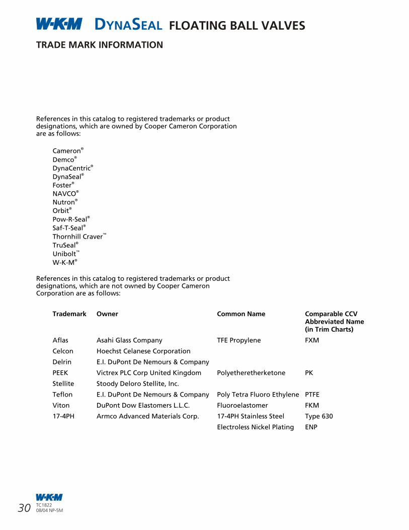
3
DYNASEAL FLOATING BALL VALVES
References in this catalog to registered trademarks or productdesignations, which are owned by Cooper Cameron Corporationare as follows:
®Cameron ®Demco
®DynaCentric®DynaSeal
®Foster®NAVCO
®Nutron®Orbit
®Pow-R-Seal®Saf-T-Seal
™Thornhill Craver®TruSeal™Unibolt
®W-K-M
References in this catalog to registered trademarks or productdesignations, which are not owned by Cooper CameronCorporation are as follows:
TRADE MARK INFORMATION
30 TC182208/04 NP-5M
TC182208/04 NP-5M
DYNASEAL 210 FLOATING BALL VALVES
UNIDIRECTIONAL BALL (OPTION)
DEMCO/W-K-M introduced the unidirectional valve option in 1979 to provide relief to valves that might have water trapped in the body cavity and then be exposed to a temporary freeze. Since this option relies on a relief hole in the ball to relieve the excess pressure the valve is stamped with a directional flow arrow to be sure the side of the ball with the hole is installed upstream.
SUPERIOR STEM JOURNAL DESIGN PREVENTS STEM SEIZUREThe stem is designed with two internal O-ring grooves located on either side of a shallow grease groove.The top O-ring is a weather seal while the bottom one seals the stem boreagainst the line media. The stem gasket provides a backup seal.The shallow groove between the O-rings provides three benefits:
• prevents stem seizure• reduces torque• provides a space for lubricating
grease applied at the factory during assembly.
TFE BODY SEALA TFE body seal is positioned between the line bore and tailpiece threads isolating the threads from the line media.
DEEP RECESSED SEATS The seat is recessed into a deep machined pocket, which serves to surround and protect the seat on all sides. This design eliminates cold flow into the valve conduit where it can be damaged by the action of the ball or the flow medium. The result is extremely long service life.(Seats are not recessed in the4 in. x 3 in. (100 mm x 80 mm)750 and 1000 psi valves).
SEAL PIN DEVICE PROVIDED AS STANDARD ON 750 AND 1000 psi,2 in., 3 in. AND 4 in.(50 mm, 80 mm AND 100 mm) REDUCED PORT VALVES.A secondary seal pin device for applying tamper detection seals is provided on these valves.These valves are a popular choice for production tank batteries where tamper detection seals are often required.
FIRE TESTED DESIGNThe W-K-M DynaSeal 210 ball valves are qualified under API Standard 607except the 4 in. x 3 in.(100 mm x 80 mm)750 and 1000 psi valves.The deep pocketed seat, locked in stem and body/ tailpiece designs give this valve excellent fire tested characteristics. (The 4 in. x 3 in. (100 mm x 80 mm)750 and 1000 psi valves do not havedeep pocketed seats).
FEATURES AND BENEFITS
LOCKING CAPABILITY IS STANDARD• The valve can be locked in the
open or closed position.
POSITIVELY RETAINED STEM• The stem is positively retained.
It is designed to prevent stem blowout while the valve is in service.
COLOR CODED WORKING PRESSURESThe lock plates are color coded so pressure ratings are quickly identified
• 750/1,000 psi green.
• 1,500 psi blue.
• 2,000 psi red.
Trademark Owner Common Name Comparable CCV Abbreviated Name (in Trim Charts)
Aflas Asahi Glass Company TFE Propylene FXM
Celcon Hoechst Celanese Corporation
Delrin E.I. DuPont De Nemours & Company
PEEK Victrex PLC Corp United Kingdom Polyetheretherketone PK
Stellite Stoody Deloro Stellite, Inc.
Teflon E.I. DuPont De Nemours & Company Poly Tetra Fluoro Ethylene PTFE
Viton DuPont Dow Elastomers L.L.C. Fluoroelastomer FKM
17-4PH Armco Advanced Materials Corp. 17-4PH Stainless Steel Type 630
Electroless Nickel Plating ENP
FLOATING BALL VALVES
© Cooper Cameron Corporation, Cooper Cameron Valves Division TC1822
Printed in Canada 08/04 NP-5M
FLOATING BALL VALVES
16500 South Main StreetMissouri City, Texas 77489281 499 8511USA Toll Free 800 323 9160www.ccvalve.com
C O O P E R C A M E R O NVALVES
USACOOPER CAMERON VALVESMissouri City, TexasPhone: 281-499-8511Fax: 281-261-3588
COOPER CAMERON VALVESOklahoma City, OklahomaPhone: 405-631-1321Fax: 405-629-0420
UKCOOPER CAMERON VALVESLivingston, ScotlandPhone: 44-1506-832-000Fax: 44-1506-432-948
CanadaCOOPER CAMERON CANADA CORPORATIONCalgary, AlbertaPhone: 403-398-9930Fax: 403-398-9936
COOPER CAMERON CANADA CORPORATIONEdmonton, AlbertaPhone: 780-435-0777Fax: 780-435-0700
MexicoCOOPER CAMERON de MEXICO S.A. de C.V.Mexico CityPhone: 52-555-580-0296Fax: 52-555-395-8669
Other Locations
Australia
Austria
Brazil
Brunei
Chile
Congo
Egypt
England
Gabon
Germany
Hungary
Indonesia
Ireland
Japan
Malaysia
Netherlands
New Zealand
Nigeria
Norway
Oman
Poland
Qatar
Russia
Saudi Arabia
UAE
Venezuela
ArgentinaCAMERON ARGENTINA S.A.I.C.Zarate, Pica Buenos AiresPhone: 54-11-4314-5520/5540Fax: 54-11-4311-2838
SingaporeCOOPER CAMERON (SINGAPORE) PTE. LTD.Phone: 65-6861-3355Fax: 65-6861-6197
FranceCAMERON FRANCE, S.A.Beziers, FrancePhone: 33-4-67-111-500Fax: 33-4-67-111-600


![WKM DynaSeal 370D4 Trunnion Ball Valves1].pdf · 4 CT-WKM-BALL-TRUN-370D4-02 06/11 SWP-3M WKM® Cameron’s Valves & Measurement (V&M) group is a leading provider of valves and measurement](https://static.documents.pub/doc/80x56/5f8a2d9802cef071943a32bf/wkm-dynaseal-370d4-trunnion-ball-valves-1pdf-4-ct-wkm-ball-trun-370d4-02-0611.jpg)
