Helwan University From the SelectedWorks of Omar H. Abdalla May, 2008 Coordinated Design of Power System Stabilizers and Static VAR Compensators in a Multimachine Power System using Genetic Algorithms Omar H. Abdalla Wedad M. Refaey Mohamed K. Saad Gamal M. Sarhan Available at: hps://works.bepress.com/omar/1/
Transcript
Helwan University
From the SelectedWorks of Omar H. Abdalla
May, 2008
Coordinated Design of Power System Stabilizersand Static VAR Compensators in a MultimachinePower System using Genetic AlgorithmsOmar H. AbdallaWedad M. RefaeyMohamed K. SaadGamal M. Sarhan
Proceedings of the 6th ICEENG Conference, 27-29 May, 2008 EE014 -
1
Military Technical College
Kobry El-Kobbah, Cairo, Egypt
6th International Conference
on Electrical Engineering ICEENG 2008
Coordinated Design of Power System Stabilizers and Static VAR
Compensators in a Multimachine Power System using Genetic Algorithms
By
Omar H. Abdalla* Wedad M. Refaey* Mohamed K. Saad** Gamal Sarhan**
Abstract: This paper presents a procedure to coordinated design of PSSs and SVCs in a multimachine power system. The aims of the proposed method are to find the best location and the optimal parameters of these compensators in order to improve the steady state and transient performances and also to increase the system damping over a wide range of operating conditions. The objective function of the GA allows the selection of the PSSs and SVCs to shift critical closed loop eigenvalues to the left-hand side in the complex s-plane. The multimachine power system considered in this study consists of nine buses, three generating units (steam, hydro and nuclear) and three static loads. Digital simulation studies show that the proposed design procedure provides good damping for the power system at different operating conditions, and moreover improves steady-state and transient performance of the system. Keywords: Power System Stabilizer, Static VAR Compensator, Genetic Algorithm, Control, eigenvalue analysis, stability.
ـــــــــــــــــــــــــــــــــــــــــــــــــــــــــــــــــــــــــــــــــــــــــــــــــــــــــــــــــــــــــــــــــــــــــــــــــــــــــــــــــــــــــــــــــ* Faculty of Engineering, University of Helwan, Cairo, Egypt
** Benha High Technology Institute, Benha, Egypt
Proceedings of the 6th ICEENG Conference, 27-29 May, 2008 EE014 -
2
1. Introduction: The design of power system stabilizers (PSSs) and static VAR compensators (SVCs) in multimachine power systems has found a considerable attention in recent decades. PSSs proved to enhance damping of electromechanical oscillations in power systems [1-3]. Static VAR compensators [4-9] have proven to be very efficient to support both voltage and reactive power, and can be used to effectively improve both steady state and transient voltage performance [5]. Various control methods have been applied to design SVCs in power systems [10-15]. Application of adaptive control SVCs is presented in [10]. Robust control design of SVCs is investigated in [11] and [12]. Fuzzy logic control techniques are used in [13] and [14] to design SVCs controllers to improve power system stability. A genetic algorithm is employed in [15] to design an SVC control system. This paper concerns with the application of GA to the design of PSSs and SVCs in a multimachine power system. The proposed genetic algorithm is employed to find the best location and optimal control parameters of the PSSs and SVCs in order to improve the steady state and transient performances. Also, it is required to increase the system damping over a wide range of operating conditions. The objective functions of the GA allow the selection of the PSS and SVC parameters to shift critical closed loop eigenvalues to the left-hand side of a vertical line in the complex s-plane. PSS and SVC are designed and tested separately. Then, system performance with these controllers is investigated over a wide range of operating conditions and when it is subjected to various types of network disturbances. The power system considered in this study consists of nine buses, three generating units and three loads. A full order nonlinear model is used to simulate the power system. A linear model is obtained by linearizing the system equations around a quiescent operating point for eigenvalue analysis. Digital simulation studies of the power system following various types of disturbances are performed to demonstrate the effectiveness of the selected PSS and SVC. The results show that the proposed GAPSS and GASVC provide good damping for the power system at different operating conditions and moreover improve the transient and dynamic performance of the system. The GA is capable of accurately determining the best location and the optimal parameters of the PSS and SVC in the power system. 2. System Modelling: The multimachine power system considered in this study consists of three generating units (steam at bus 1, hydro at bus 2 and nuclear at bus 3) interconnected through a transmission network and three constant impedance loads [16]. The one line diagram of
Proceedings of the 6th ICEENG Conference, 27-29 May, 2008 EE014 -
3
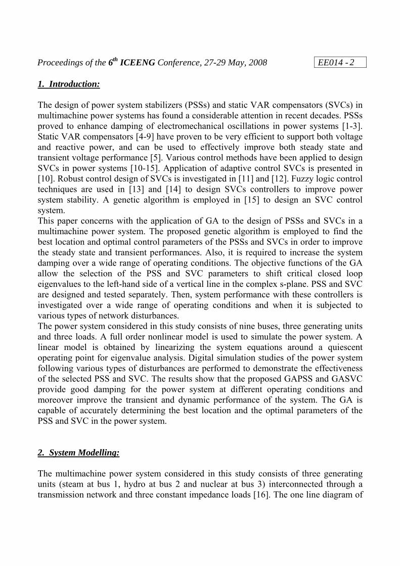
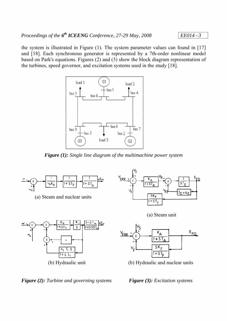
the system is illustrated in Figure (1). The system parameter values can found in [17] and [18]. Each synchronous generator is represented by a 7th-order nonlinear model based on Park's equations. Figures (2) and (3) show the block diagram representation of the turbines, speed governor, and excitation systems used in the study [18].
Figure (1): Single line diagram of the multimachine power system (a) Steam and nuclear units (a) Steam unit (b) Hydraulic unit (b) Hydraulic and nuclear units Figure (2): Turbine and governing systems Figure (3): Excitation systems
Proceedings of the 6th ICEENG Conference, 27-29 May, 2008 EE014 -
4
The power system stabilizer (PSS) considered here is a speed stabilizer applied on the voltage regulator loop of the synchronous generator. A signal from the generator shaft speed is added through the PSS to the reference of the voltage regulator. The transfer function of the PSS is given in Eq. (1). It consists of a gain Kg, washout filter, and a lead-lag network.
)1)(1()1)(1(
1)(
42
31
5
5
sTsTsTsT
sTsTKsG g ++
+++
= (1)
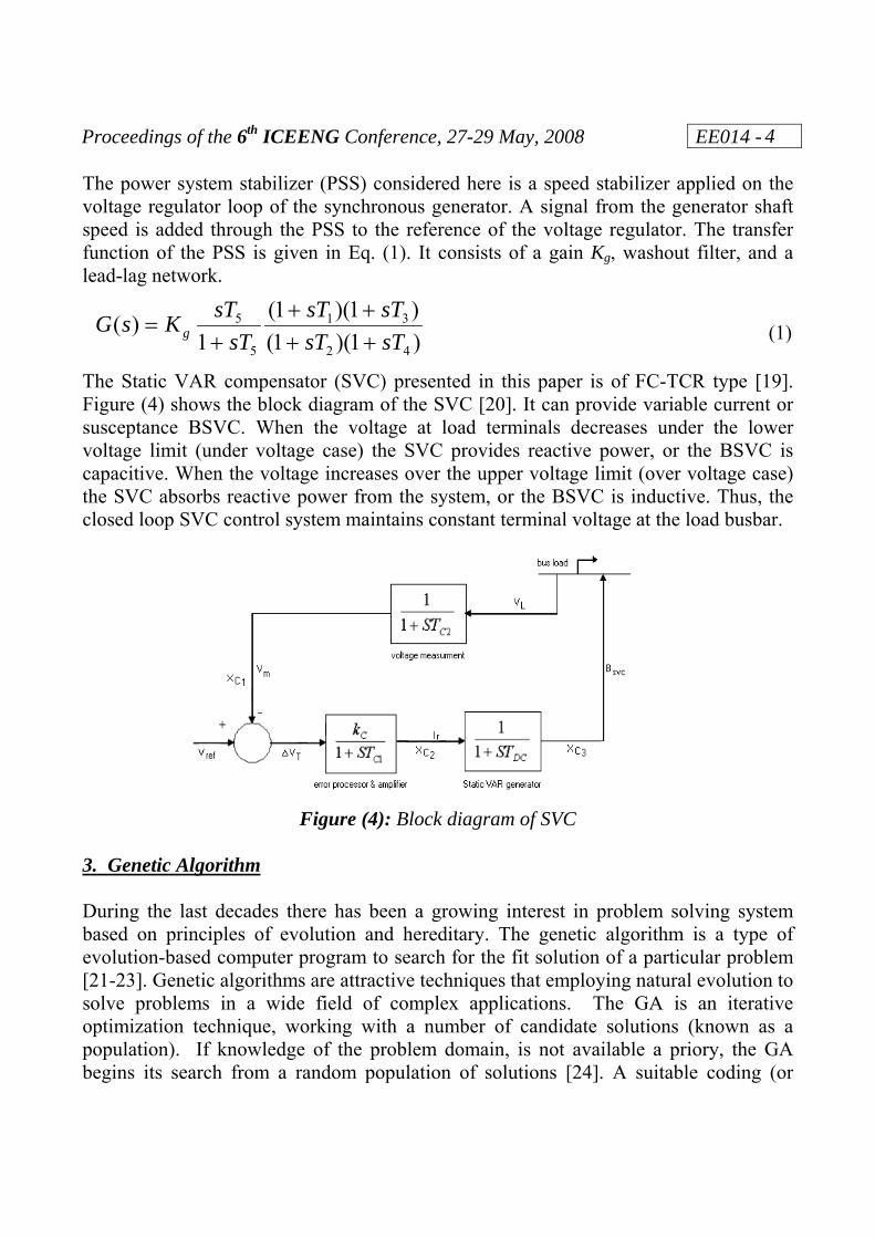
The Static VAR compensator (SVC) presented in this paper is of FC-TCR type [19]. Figure (4) shows the block diagram of the SVC [20]. It can provide variable current or susceptance BSVC. When the voltage at load terminals decreases under the lower voltage limit (under voltage case) the SVC provides reactive power, or the BSVC is capacitive. When the voltage increases over the upper voltage limit (over voltage case) the SVC absorbs reactive power from the system, or the BSVC is inductive. Thus, the closed loop SVC control system maintains constant terminal voltage at the load busbar.
Figure (4): Block diagram of SVC 3. Genetic Algorithm During the last decades there has been a growing interest in problem solving system based on principles of evolution and hereditary. The genetic algorithm is a type of evolution-based computer program to search for the fit solution of a particular problem [21-23]. Genetic algorithms are attractive techniques that employing natural evolution to solve problems in a wide field of complex applications. The GA is an iterative optimization technique, working with a number of candidate solutions (known as a population). If knowledge of the problem domain, is not available a priory, the GA begins its search from a random population of solutions [24]. A suitable coding (or
Proceedings of the 6th ICEENG Conference, 27-29 May, 2008 EE014 -
5
representation) for the problem to be solved, must be defined first. I addition, a fitness function should be defined to assign a figure of merit to each coding solution. During the run, if the termination condition is not satisfied, parents must be selected for reproduction. Then, these are recombined to generate offspring using the reproduction, crossover and mutation operators to update the population of candidate solutions. Usually, a simple genetic algorithm consists of three operators: selection, crossover, and mutation. The application of these operations produces new strings (offspring), new population, and new generation, respectively. The overall process is then repeated with the new generation until the appropriate criterion is clearly satisfied. 4. Problem Formulation 4.1. Eigenvalue analysis The nonlinear differential equations that describe the multimachine power system can be linearized about any particular operating point. A linearized model of the multimachine power system is obtained in the standard state-space form [18]:
BUA +Χ=Χ•
(2) Where X is the state vector, U is the input vector, A is the state coefficient matrix, and B is the input coefficient matrix. The model can be derived by linearizing the nonlinear equations of the system (generators, exciters, AVR, speed governors, and SVC). The components of X and U are the deviations of the variables from their corresponding steady-state values. The eigenvalues of the matrix A in Eq. (2) contain the necessary information on the small-signal stability of the multimachine system [18]. The system is stable if all the eigenvalues lie on the left-hand side of the s-plane. The real eigenvalues are related to exponential components in the time response. The complex conjugate pairs of eigenvalues are associated with the oscillatory modes in the time response. They have the form:
βαλ j±−= (3)
β gives the frequency of the oscillations in rad/sec and the value of α1 defines the time constant by which the magnitude of the oscillation is decayed. Studies of the effects of changes in operating conditions and system parameters lead to the identification of the eigenvalues which may cause instability. The most important eigenvalues are those related to rotor oscillations. In this case the eigenvalues are constrained to lie to the left of a vertical line corresponding to a specified damping ratio.
Proceedings of the 6th ICEENG Conference, 27-29 May, 2008 EE014 -
6
4.2 Selection of PSS and SVC The problem is to design suitable PSS and SVC controllers for the multimachine power system. The goals of this approach are to provide voltage and reactive power support and to improve the damping of system oscillations by selecting the best location and parameter values of the PSS and SVC controllers. First, we design the required GA-PSS for the power system using GA techniques. The objective functions of GA-PSS and eigenvalue analysis allow determining the best location and selecting the optimal parameters of GA-PSS. Then, the GA-SVC is designed using the same design procedure. The performances of the power system with both GA-PSS and GA-SVC are investigated over wide operating conditions and various types of network disturbances.
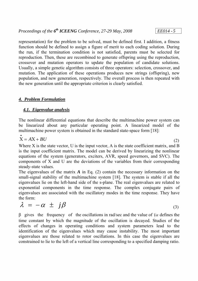
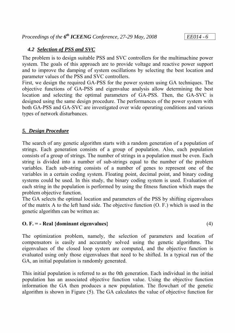
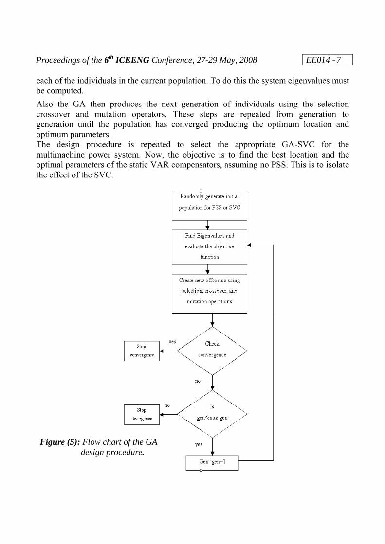
5. Design Procedure The search of any genetic algorithm starts with a random generation of a population of strings. Each generation consists of a group of population. Also, each population consists of a group of strings. The number of strings in a population must be even. Each string is divided into a number of sub-strings equal to the number of the problem variables. Each sub-string consists of a number of genes to represent one of the variables in a certain coding system. Floating point, decimal point, and binary coding systems could be used. In this study, the binary coding system is used. Evaluation of each string in the population is performed by using the fitness function which maps the problem objective function. The GA selects the optimal location and parameters of the PSS by shifting eigenvalues of the matrix A to the left hand side. The objective function (O. F.) which is used in the genetic algorithm can be written as: O. F. = - Real {dominant eigenvalues} (4) The optimization problem, namely, the selection of parameters and location of compensators is easily and accurately solved using the genetic algorithms. The eigenvalues of the closed loop system are computed, and the objective function is evaluated using only those eigenvalues that need to be shifted. In a typical run of the GA, an initial population is randomly generated. This initial population is referred to as the 0th generation. Each individual in the initial population has an associated objective function value. Using the objective function information the GA then produces a new population. The flowchart of the genetic algorithm is shown in Figure (5). The GA calculates the value of objective function for
Proceedings of the 6th ICEENG Conference, 27-29 May, 2008 EE014 -
7
each of the individuals in the current population. To do this the system eigenvalues must be computed. Also the GA then produces the next generation of individuals using the selection crossover and mutation operators. These steps are repeated from generation to generation until the population has converged producing the optimum location and optimum parameters. The design procedure is repeated to select the appropriate GA-SVC for the multimachine power system. Now, the objective is to find the best location and the optimal parameters of the static VAR compensators, assuming no PSS. This is to isolate the effect of the SVC.
Figure (5): Flow chart of the GA
design procedure.
Proceedings of the 6th ICEENG Conference, 27-29 May, 2008 EE014 -
8
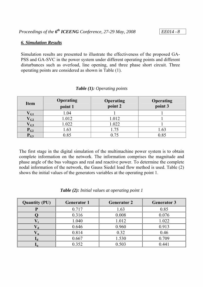
6. Simulation Results Simulation results are presented to illustrate the effectiveness of the proposed GA-PSS and GA-SVC in the power system under different operating points and different disturbances such as overload, line opening, and three phase short circuit. Three operating points are considered as shown in Table (1).
The first stage in the digital simulation of the multimachine power system is to obtain complete information on the network. The information comprises the magnitude and phase angle of the bus voltages and real and reactive power. To determine the complete nodal information of the network, the Gauss Siedel load flow method is used. Table (2) shows the initial values of the generators variables at the operating point 1.
Proceedings of the 6th ICEENG Conference, 27-29 May, 2008 EE014 -
9
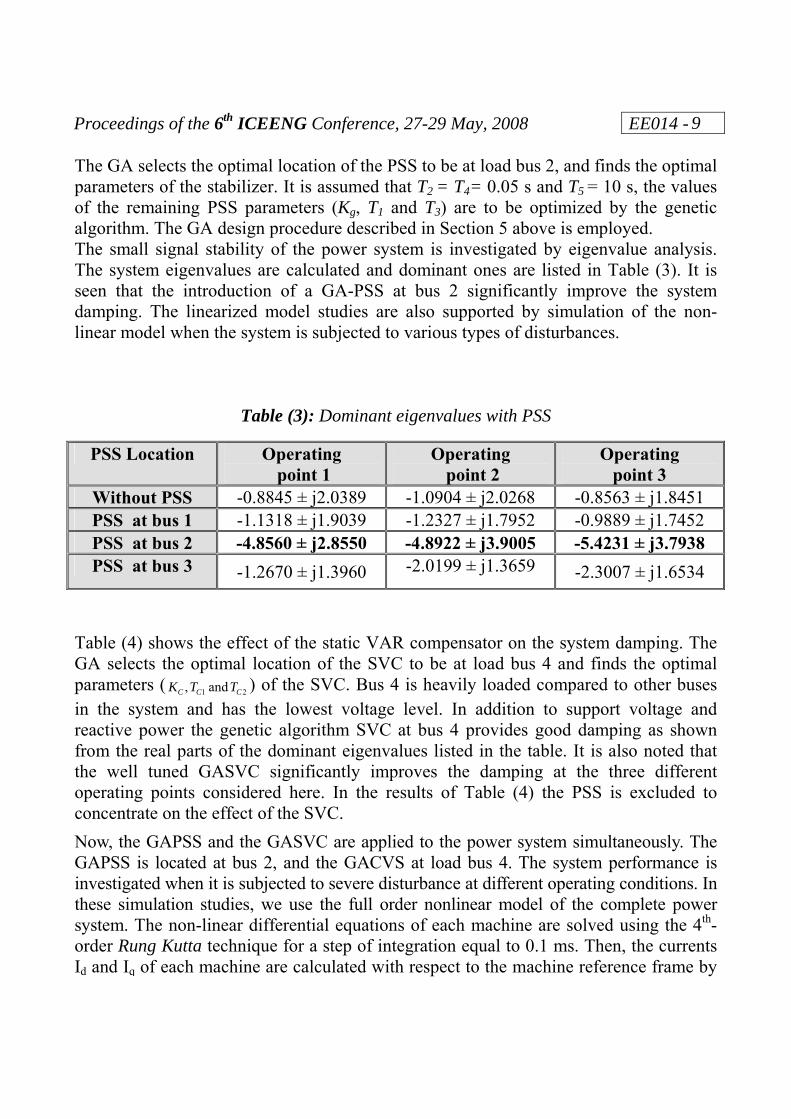
The GA selects the optimal location of the PSS to be at load bus 2, and finds the optimal parameters of the stabilizer. It is assumed that T2 = T4= 0.05 s and T5 = 10 s, the values of the remaining PSS parameters (Kg, T1 and T3) are to be optimized by the genetic algorithm. The GA design procedure described in Section 5 above is employed. The small signal stability of the power system is investigated by eigenvalue analysis. The system eigenvalues are calculated and dominant ones are listed in Table (3). It is seen that the introduction of a GA-PSS at bus 2 significantly improve the system damping. The linearized model studies are also supported by simulation of the non-linear model when the system is subjected to various types of disturbances.
Table (3): Dominant eigenvalues with PSS
PSS Location Operating point 1
Operating point 2
Operating point 3
Without PSS -0.8845 ± j2.0389 -1.0904 ± j2.0268 -0.8563 ± j1.8451 PSS at bus 1 -1.1318 ± j1.9039 -1.2327 ± j1.7952 -0.9889 ± j1.7452 PSS at bus 2 -4.8560 ± j2.8550 -4.8922 ± j3.9005 -5.4231 ± j3.7938 PSS at bus 3 -1.2670 ± j1.3960 -2.0199 ± j1.3659 -2.3007 ± j1.6534
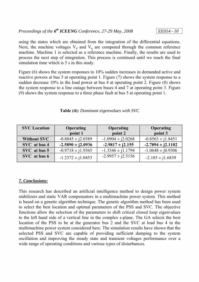
Table (4) shows the effect of the static VAR compensator on the system damping. The GA selects the optimal location of the SVC to be at load bus 4 and finds the optimal parameters ( 21 and , CCC TTK ) of the SVC. Bus 4 is heavily loaded compared to other buses in the system and has the lowest voltage level. In addition to support voltage and reactive power the genetic algorithm SVC at bus 4 provides good damping as shown from the real parts of the dominant eigenvalues listed in the table. It is also noted that the well tuned GASVC significantly improves the damping at the three different operating points considered here. In the results of Table (4) the PSS is excluded to concentrate on the effect of the SVC. Now, the GAPSS and the GASVC are applied to the power system simultaneously. The GAPSS is located at bus 2, and the GACVS at load bus 4. The system performance is investigated when it is subjected to severe disturbance at different operating conditions. In these simulation studies, we use the full order nonlinear model of the complete power system. The non-linear differential equations of each machine are solved using the 4th-order Rung Kutta technique for a step of integration equal to 0.1 ms. Then, the currents Id and Iq of each machine are calculated with respect to the machine reference frame by
Proceedings of the 6th ICEENG Conference, 27-29 May, 2008 EE014 -
10
using the states which are obtained from the integration of the differential equations. Next, the machine voltages Vd and Vq are computed through the common reference machine. Machine 1 is selected as a reference machine. Finally, the results are used to process the next step of integration. This process is continued until we reach the final simulation time which is 5 s in this study.
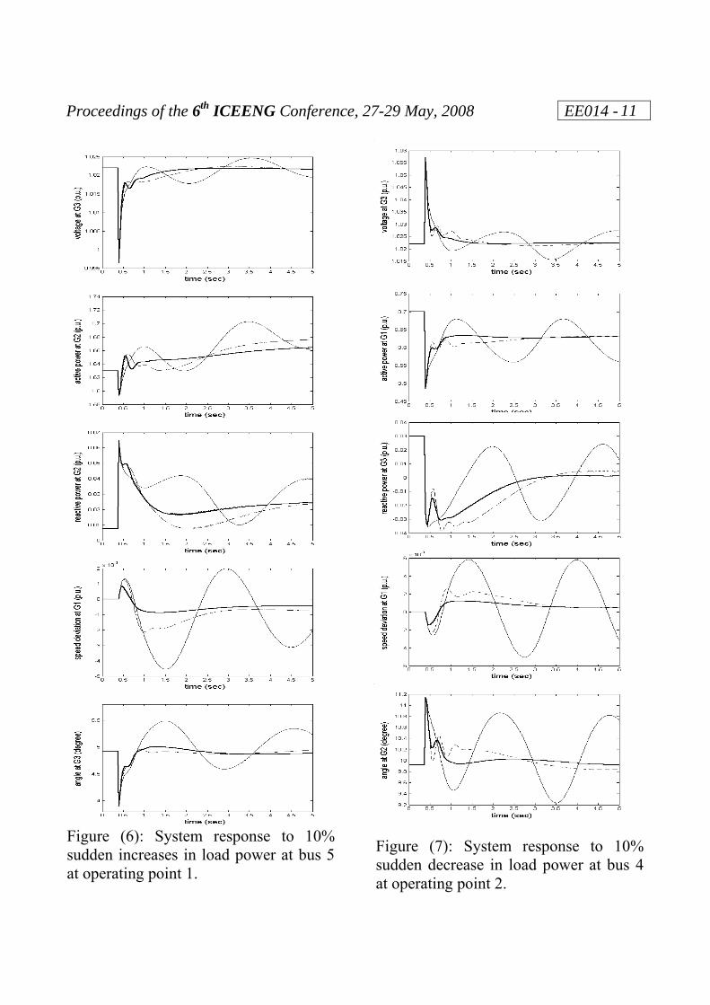
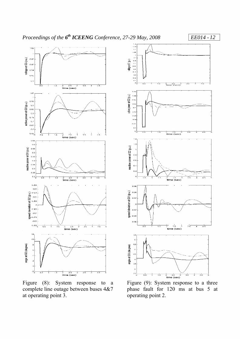
Figure (6) shows the system responses to 10% sudden increases in demanded active and reactive powers at bus 5 at operating point 1. Figure (7) shows the system response to a sudden decrease 10% in the load power at bus 4 at operating point 2. Figure (8) shows the system response to a line outage between buses 4 and 7 at operating point 3. Figure (9) shows the system response to a three phase fault at bus 5 at operating point 1.
Table (4): Dominant eigenvalues with SVC
SVC Location Operating point 1
Operating point 2
Operating point 3
Without SVC -0.8845 ± j2.0389 -1.0904 ± j2.0268 -0.8563 ± j1.8451 SVC at bus 4 -2.5890 ± j2.0936 -2.9817 ± j2.155 -2.7894 ± j2.1102 SVC at bus 5 -0.9718 ± j1.9365 -1.3346 ± j1.1794 -1.0648 ± j0.9306 SVC at bus 6 -1.2372 ± j1.0453 -2.9957 ± j2.5156 -2.103 ± j1.6839
7. Conclusions: This research has described an artificial intelligence method to design power system stabilizers and static VAR compensators in a multimachine power system. This method is based on a genetic algorithm technique. The genetic algorithm method has been used to select the best location and optimal parameters of the PSS and SVC. The objective functions allow the selection of the parameters to shift critical closed loop eigenvalues to the left hand side of a vertical line in the complex s-plane. The GA selects the best location of the PSS to be at the generator bus 2 and the SVC at load bus 4 in the multimachine power system considered here. The simulation results have shown that the selected PSS and SVC are capable of providing sufficient damping to the system oscillation and improving the steady state and transient voltages performance over a wide range of operating conditions and various types of disturbances.
Proceedings of the 6th ICEENG Conference, 27-29 May, 2008 EE014 -
11
Figure (6): System response to 10% sudden increases in load power at bus 5 at operating point 1.
Figure (7): System response to 10% sudden decrease in load power at bus 4 at operating point 2.
Proceedi
Figure completeat operati
ings of the
(8): Syse line outaing point 3
e 6th ICEE
tem respage betwee3.
ENG Confe
ponse toen buses 4
ference, 27
a 4&7
7-29 May,
Figure (9phase fauoperating
2008
9): Systemult for 1
g point 2.
m respons120 ms a
EE014 - 1
e to a thrat bus 5
12
ree at
Proceedings of the 6th ICEENG Conference, 27-29 May, 2008 EE014 -
13
The following notations have been used in the results shown in Figures (6) to (9).
References: [1] E. V. Larsen and D. A. Swann, Applying Power System Stabilizers, Parts I-III,
IEEE Transactions on Power Apparatus and Systems, Vol. PAS-100, No. 6, pp. 3017-3046, June 1981.
[2] Y. Y. Hsu and K. L. Lious, Design of Self Tuning PID Power System Stabilizer for Synchronous Generators, IEEE Transactions on Energy Conversion, Vol. 2, No. 3, pp. 343-348, 1987.
[3] S. Chen and O. P. Malik, Power System Stabilizer Design Using μ Synthesis, IEEE Transactions on Energy Conversion, Vol. 10, No. 1, pp. 175-181, 1995.
[4] A. E. Hammad, Analysis of Power System Stability Enhancement by Static VAR Compensators, IEEE Transactions on Power Systems, Vol. 1, No. 4, pp. 222-227, 1986.
[5] E. Z. Zhou, Applications of Static VAR Compensators to Increase Power System Damping, IEEE Transactions on Power Systems Vol. 8, No. 2, pp. 655-661, 1993.
[6] H. F. Wang and F. I. Swift, Capability of the Static VAR Compensator in Damping Power System Oscillations, Proceedings IEE Part C, Generation, Transmission & Distribution, Vol. 143, No. 4, pp. 353-358, 1996.
[7] A. R. Messina, O. Begovich and M. Nayebzadeh, Analytical Investigation of Use of Static VAR Compensators to Aid Damping of Interarea Oscillations, Electric Power System Research, Vol. 51, pp. 199-210, 1999.
[8] X. Yu, M. Khammash and V. Vittal, Robust Design of a Damping Controller for Static VAR Compensators in Power Systems, IEEE Transactions on Power Systems, Vol. 16, No. 3, pp. 456-462, 2001.
[9] F. Puorboghrat et al, Local Sliding Control for Damping Interarea Power Oscillations, IEEE Transactions on Power Systems, Vol. 19, No. 2, pp. 1123-1134, 2004.
[10] P. K. Dash et al, Adaptive Controller for Static Reactive Power Compensators in Power Systems, Proceedings IEE, Part C, Generation, Transmission & Distribution, Vol. 134, No. 3, pp. 256-264, 1987.
[11] Q. Zhao and J. Jiang, Robust SVC Controller Design for Improving Power System Damping, IEEE Transactions on Power Systems, Vol. 10, No. 9, pp. 1927-1932, 1995.
Without PSS & SVC With PSS on bus 2 With PSS on bus 2 & SVC on bus 4
Proceedings of the 6th ICEENG Conference, 27-29 May, 2008 EE014 -
14
[12] M. Parniani and M. R. Irvani, Optimal Robust Control Design of Static VAR Compensators, Proceedings IEE, Part C, Generation, Transmission & Distribution, Vol. 145, No. 3, pp. 301-307, 1998.
[13] P. K. Dash, S. Mishra and A. C. Liew, Fuzzy Logic Based VAR Stabilizer for Power System Control, Proceedings IEE, Part C, Generation, Transmission & Distribution, Vol. 142, No. 6, pp. 618-624, 1995.
[14] K. L. Lo and M. O. Sadegh, Systematic Method for the Design of a Full-Scale Fuzzy PID Controller for SVC to Control Power System Stability, Proceedings IEE, Part C, Generation, Transmission & Distribution, Vol. 150, No. 3, pp. 297-304, 2003.
[15] P. Ju, E. Handschin and F. Reyer, Genetic Algorithm Aided Controller Design with Application to SVC", Proceedings IEE, Part C, Generation, Transmission & Distribution, Vol. 143, No. 3, pp. 258-262, 1996.
[16] A. A. Nour-Eldeen, W. M. Refaey and O. H. Abdalla, Identification and Static VAR Control of a Multimachine Power System, Proceedings of the Fifth International Middle East Power Systems Conference MEPCON’97, pp. 1734-1740, 1997.
[17] P. M. Anderson and A. A. Fouad, Power System Control and Stability, Iowa State University Press, 1977.
[18] O. H. Abdalla, S. A. Hassan, and N. T. Tweig, Coordinated Stabilization of a Multimachine Power System, IEEE Transactions on Power Apparatus and Systems, Vol. PAS-103, No. 3, pp. 483-493, 1984.
[19] R. T. Byerly, D. T. Penmariak and E. R. Taylor, Static Reactive Compensation for Power Transmission Systems, IEEE Transactions on Power Apparatus and Systems, Vol. PAS-101, No. 10, pp. 3997-4006, 1982.
[20] H. A. Perez, E. Acha, and C. R. Fuerte, Advanced SVC Models for Newton Raphson Load Flow and Newton Optimal Power Flow Studies, IEEE Transactions on Power Systems, Vol. 15, No. 1, pp. 129-136, 2000.
[21] D. E. Goldberg, Genetic Algorithms in Search, Optimization, and Machine Learning, Addison-Wesley, 1989.
[22] D. E. Goldberg, Genetic and Evolutionary Algorithms Come of Age, Communications of the ACM, Vol. 37, No. 3, pp. 113-119, 1994.
[23] Z. Michalewicz, Genetic Algorithms + Data Structure = Evolutionary Programs, Springer-Verag, Berlin Heidelberg, 1996.
[24] D. Dracopoulos, Genetic Algorithms and Genetic Programming for Control, In Dasgupta and Michalewicz (eds.), Evolutionary Algorithms in Engineering Applications, Spriger-Verlag, 1997.