Introduction to this workbook, and some user notes
A This workbook allows data to be collected and analysed for assessing the SIL requirement for a SIF.B The sheet "Blank low demand" is a master and should be copied and used for each SIF to be considered. Ideally the tab name would be changed as well for easy navigation when there are lots of SIF worksheets.C The Company target tolerability levels used throughout this workbook should be entered in the sheet "TOR"D Use the duplicate Worksheets for each SIF
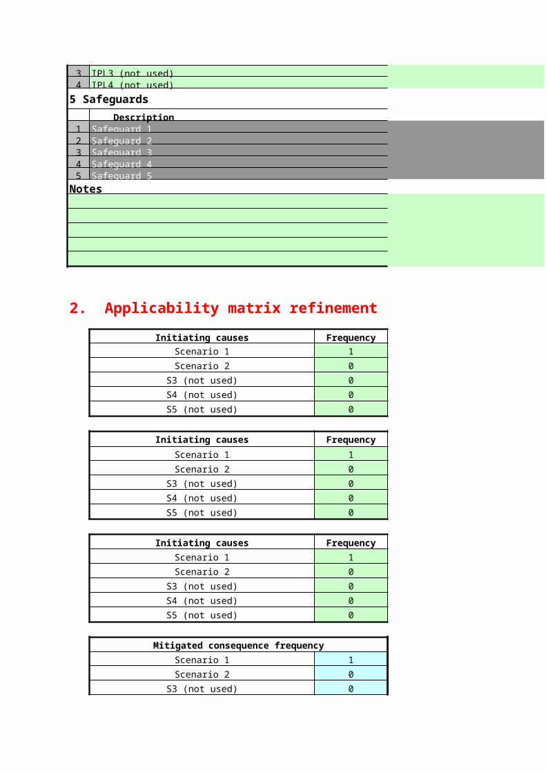
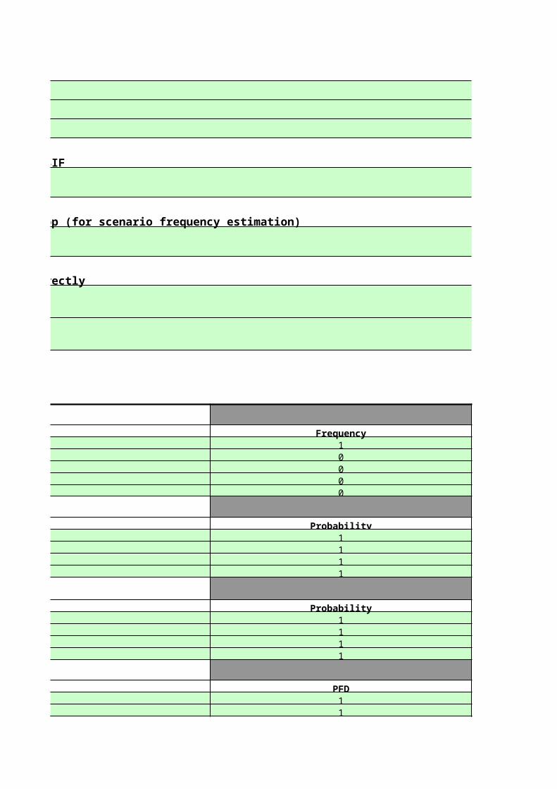
1 Fields where data can be entered are shaded green - fill them in as required. If it has a black border it has restricted input - click the cell, click the little down arrow that appears, then click your choice.2 Fields where there should be no user entry are locked.3 Several scenarios (possible causes) to the same consequent incident can be analysed on the same worksheet.4 Enter the scenarios in section 15 Enter ALL Enabling Conditions, Conditional Modifiers and Independent Protection Layers and the probabilities / PFDs in sections 2 to 4. Don't worry if they don't apply to all scenarios at this stage.6 In the Applicability Matrix section below the data input, you will find that the data entered in steps 4 and 5 above have been copied into the table.7 Alter any probability or PFD data in the table if it is not applicable. So if, for example, Layer of Protection 1 was not applicable to Scenario 1, then over-write the value 1 in cell F77 with the value 0.
If you alter a value in the matrix from the value entered in the data input section it will turn red to show that it will no longer be updated if you alter the data in the data input section.8 Input data for the severity of the incident in the Assessment section below the Matrix. These are multiple choice fields and select tolerability values shown in the Tolerability of Risk sheet ("TOR").
The workbook shows all three key values for the risk type and severity category selected.9 The workbook then shows the required PFD from any additional protection required to make the situation meet the key values, and the SIL value it would require.
If the target is already met and no further equipment is required, the worksheet shows this.10 If the system does not meet the key value selected to be met, you can select a further protection layer level from the list and the worksheet indicates whether or not this is sufficient.11 Fields that are calculated are shaded blue - do not fill them in unless you mean to over-write the formula
E Some data for use in the worksheets are shown in the sheets with blue tabs. Substitute Company data if available. The best data to use is that resulting from practical experience in the Company in question.F Enter the Company view of the PFDs of safety devices in the following table:
SIL 1 device 0.1SIL 2 device 0.01SIL 3 device 0.001SIL 4 device 0.0001 These are copied onto the individual SIL assessment sheets
Bursting disc 0.01 Revised values in the given SIL band can be substituted if appropriate.
Relief valve 0.05BPCS 0.1
G Sheet "IPL checklist" shows some criteria to be applied to systems being considered as Independent Protection Layers before entering them into section 4. It can be copied into the worksheets if needed.H Spreadsheets are locked to prevent inadvertant data entry or alteration. They can be unlocked if needed.I Some cells at the top of column I in the Worksheets are used in the calculations and for input validation, and are in light grey - do not alter! Cell F105 is also used but in white font - don't alter this!J Data provided in this workbook is taken from CEDCS general experience from various root sources and should be checked before use for any clientK Some clips from the CCPS book "Layers of Protection Analysis" ISBN 0-8169-0811-7 were shown here. Permission for this has been applied for but not yet received - versions sent out have had these deletedL The Tolerability of Risk table is an example and should be adjusted to suit the client situation if necessary.
DISCLAIMERThis workbook is provided without guarantee. Whilst every care has been taken in its design and content, it is the responsibility of the user to ensure that the results are accurate for the purpose intended
The sheet "Blank low demand" is a master and should be copied and used for each SIF to be considered. Ideally the tab name would be changed as well for easy navigation when there are lots of SIF worksheets.The Company target tolerability levels used throughout this workbook should be entered in the sheet "TOR"
Fields where data can be entered are shaded green - fill them in as required. If it has a black border it has restricted input - click the cell, click the little down arrow that appears, then click your choice.
Several scenarios (possible causes) to the same consequent incident can be analysed on the same worksheet.
Enter ALL Enabling Conditions, Conditional Modifiers and Independent Protection Layers and the probabilities / PFDs in sections 2 to 4. Don't worry if they don't apply to all scenarios at this stage.In the Applicability Matrix section below the data input, you will find that the data entered in steps 4 and 5 above have been copied into the table.Alter any probability or PFD data in the table if it is not applicable. So if, for example, Layer of Protection 1 was not applicable to Scenario 1, then over-write the value 1 in cell F77 with the value 0.If you alter a value in the matrix from the value entered in the data input section it will turn red to show that it will no longer be updated if you alter the data in the data input section.Input data for the severity of the incident in the Assessment section below the Matrix. These are multiple choice fields and select tolerability values shown in the Tolerability of Risk sheet ("TOR").
The workbook then shows the required PFD from any additional protection required to make the situation meet the key values, and the SIL value it would require.
If the system does not meet the key value selected to be met, you can select a further protection layer level from the list and the worksheet indicates whether or not this is sufficient.Fields that are calculated are shaded blue - do not fill them in unless you mean to over-write the formula
Some data for use in the worksheets are shown in the sheets with blue tabs. Substitute Company data if available. The best data to use is that resulting from practical experience in the Company in question.
These are copied onto the individual SIL assessment sheetsRevised values in the given SIL band can be substituted if appropriate.
Sheet "IPL checklist" shows some criteria to be applied to systems being considered as Independent Protection Layers before entering them into section 4. It can be copied into the worksheets if needed.Spreadsheets are locked to prevent inadvertant data entry or alteration. They can be unlocked if needed.Some cells at the top of column I in the Worksheets are used in the calculations and for input validation, and are in light grey - do not alter! Cell F105 is also used but in white font - don't alter this!Data provided in this workbook is taken from CEDCS general experience from various root sources and should be checked before use for any clientSome clips from the CCPS book "Layers of Protection Analysis" ISBN 0-8169-0811-7 were shown here. Permission for this has been applied for but not yet received - versions sent out have had these deletedThe Tolerability of Risk table is an example and should be adjusted to suit the client situation if necessary.
This workbook is provided without guarantee. Whilst every care has been taken in its design and content, it is the responsibility of the user to ensure that the results are accurate for the purpose intended
The sheet "Blank low demand" is a master and should be copied and used for each SIF to be considered. Ideally the tab name would be changed as well for easy navigation when there are lots of SIF worksheets.
Fields where data can be entered are shaded green - fill them in as required. If it has a black border it has restricted input - click the cell, click the little down arrow that appears, then click your choice.
Some data for use in the worksheets are shown in the sheets with blue tabs. Substitute Company data if available. The best data to use is that resulting from practical experience in the Company in question.
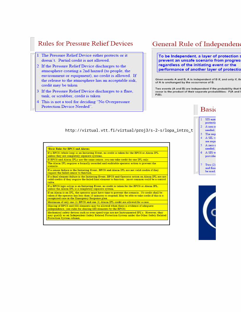
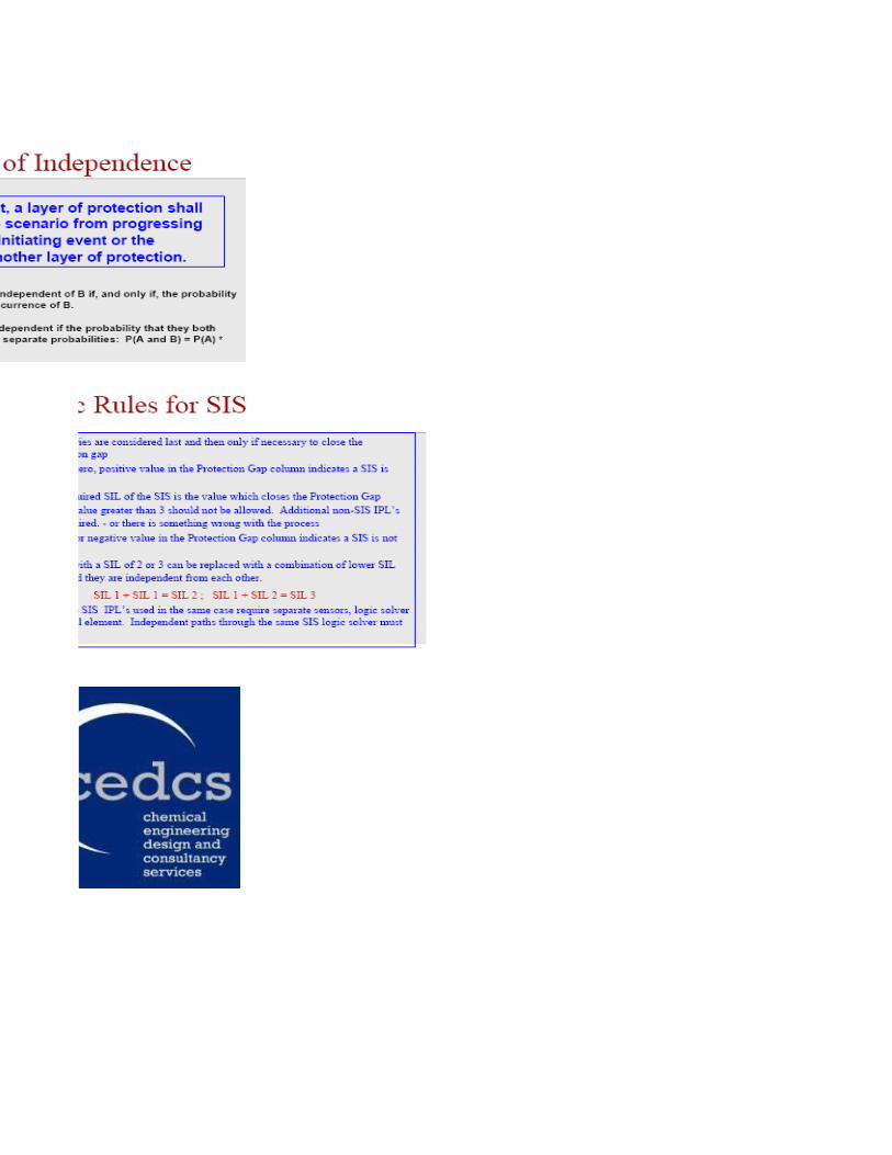
Some clips from the CCPS book "Layers of Protection Analysis" ISBN 0-8169-0811-7 were shown here. Permission for this has been applied for but not yet received - versions sent out have had these deleted
This workbook is provided without guarantee. Whilst every care has been taken in its design and content, it is the responsibility of the user to ensure that the results are accurate for the purpose intended
document.xls TOR 04/17/2023
Tolerability of Risk
Personnel injury & health HSE / media Broadly Acceptable Company Maximum Target Intolerable
51.0E-06 1.0E-05 1.0E-04
Name: TOR_Personal
41.0E-06 1.0E-04 1.0E-03
3Reportable injury or injuries. People hospitalised. 1.0E-04 1.0E-03 0.1
2 Reportable injury or injuries. 0.01 0.1 1
1No external effect 0.1 1 1
Environmental HSE / media Broadly Acceptable Company Maximum Target Intolerable
52.0E-06 2.0E-05 2.0E-04
Name: TOR_Environment
4Significant local environmental damage 2.0E-06 2.0E-04 2.0E-03
32.0E-04 2.0E-03 0.2
20.02 0.2 2
1No external effect 0.2 2 2
Assets HSE / media Broadly Acceptable Company Maximum Target Intolerable
5Not used in this study Not used in this study
Name: TOR_Assets
4 Not used in this study Not used in this study
3 Not used in this study Not used in this study
2 Not used in this study Not used in this study
1Not used in this study Not used in this study
Units: incidents per year
Category 5 – extremely serious consequences
Two to five fatalities onsite.Fatality or serious injuries offsiteMajor health effects to many people
International news coverage.Site closure threatened
Category 4 – major consequences
Single onsite fatality.Many serious injuries onsite.Serious offsite injuries.
National news coverage.Prosecution by authoritiesSite closure threatened
Category 3 – severe consequences
Many complaints. Prosecution or formal cautionNational attention
Category 2 – serious consequences
Some complaints. HSE warning.
Category 1 – minor consequences
Minor injury on-site, not reportable. Possible exposure to chemicalsIll effect on some employees
Category 5 – extremely serious consequences
Significant environmental damage. International news coverage.Site closure threatened
Category 4 – major consequences
National news coverage.Prosecution by authoritiesSite closure threatened
Category 3 – severe consequences
Large loss of listed substance.Fire and smoke
Many complaints. Prosecution or formal cautionNational attention
Category 2 – serious consequences
Significantly exceeding consents. Significant loss of listed material. Toxic gas cloud, some killed wildlife.
Some complaints. HSE warning.
Category 1 – minor consequences
Contained spillageMinor loss of chemical outside plant / visible plume. Sustained noise or nuisance
Category 5 – extremely serious consequences
Category 4 – major consequences
Category 3 – severe consequences
Category 2 – serious consequences
Category 1 – minor consequences
A B C D E F G H I J K L1
2
345
6
7
8
9
10
11
12
13
14
15
16
17
18
19
20
21
22
23
24
25
2627
Title of eventTitle of equipmentSIF reference
Description of scenario of operation of the SIF
Observed previous operation of the SIF or loop (for scenario frequency estimation)
Consequence of failure of SIF to operate correctly
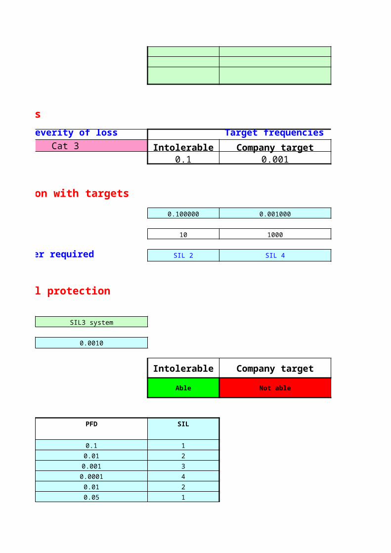
1. Type of loss 2. Severity of lossPersonnel safety Cat 3
4. Results - comparison of prediction with targets
Required PFD (maximum value)
Protection factor (minimum value)
SIL class of additional protective layer required
5. Assessment of proposed additional protection
Type of device proposed
Attributed PFD
Ability to meet each criterion:
SIL 1 device
SIL 2 device
SIL 3 device
SIL 4 device
Bursting disc
Relief valve
Assumed values for safety devices on this sheet (see cell comment)
C119
These data are initially those input in the sheet "Introduction". The values can be over-written if a better value for the loop proposed is available. This value must be in the range appropriate for the SIL rating shown, ie SIL1 - 0.1>PFS>0.01 SIL2 - 0.01>PFS>0.001 SIL3 - 0.001>PFS>0.0001 SIL4 - 0.0001>PFS>0.00001
BPCS
C126
Only allowed if not already included in the IPLs
Description of scenario of operation of the SIF
Observed previous operation of the SIF or loop (for scenario frequency estimation)
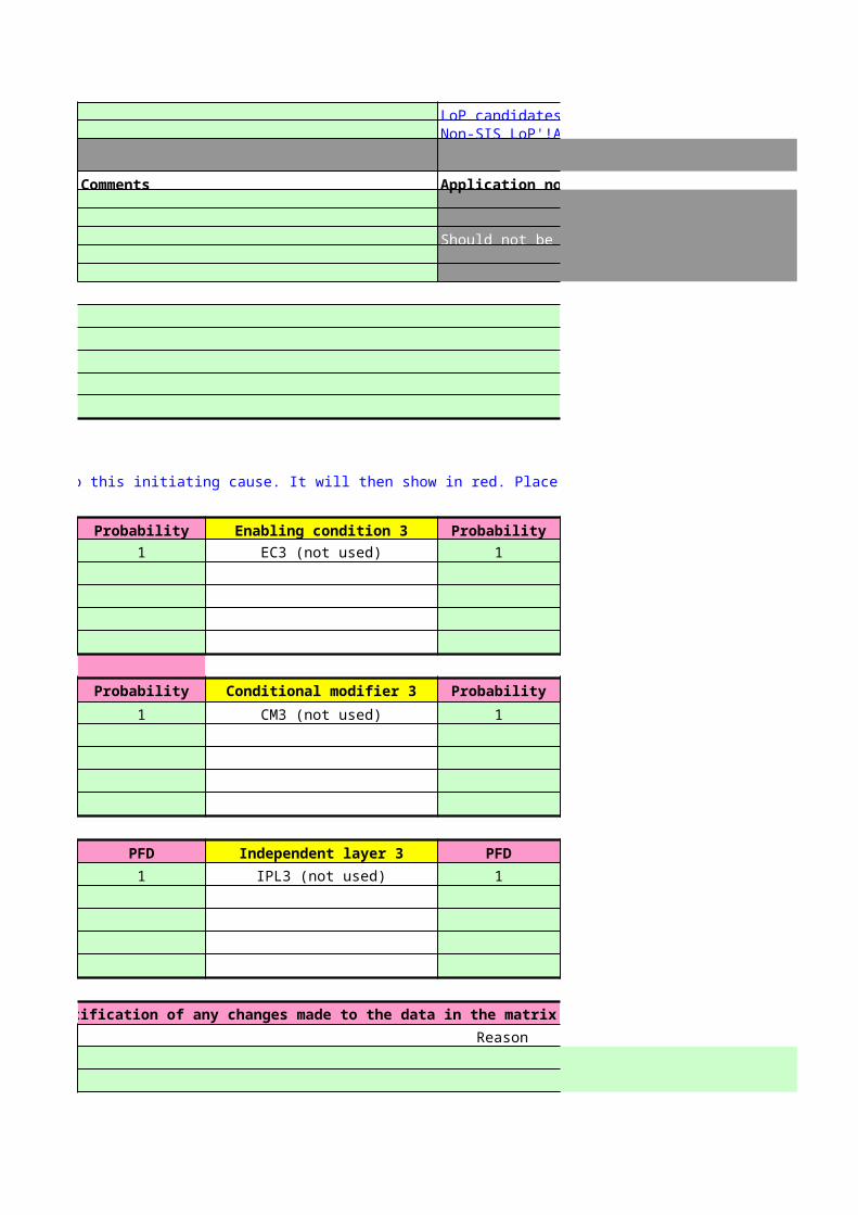
Overtype the probability value to 0, if the consideration does not apply to this initiating cause. It will then show in red. Place justification of the change in the table below.
Enabling condition 1 Probability Enabling condition 2
Description of EC1 1 EC2 (not used)
Description of EC1 1 EC2 (not used)
Description of EC1 1 EC2 (not used)
Description of EC1 1 EC2 (not used)
Description of EC1 1 EC2 (not used)
Conditional modifier 1 Probability Conditional modifier 2
Description of CM1 1 CM2 (not used)
Description of CM1 1 CM2 (not used)
Description of CM1 1 CM2 (not used)
Description of CM1 1 CM2 (not used)
Description of CM1 1 CM2 (not used)
Independent layer 1 PFD Independent layer 2
Description of ILP1 1 IPL2 (not used)
Description of ILP1 1 IPL2 (not used)
Description of ILP1 1 IPL2 (not used)
Description of ILP1 1 IPL2 (not used)
Description of ILP1 1 IPL2 (not used)
Justification of any changes made to the data in the matrix
Cell Change
2. Severity of loss Target frequencies (from TOR sheet)Cat 3 Intolerable Company target
0.1 0.001
4. Results - comparison of prediction with targets
0.100000 0.001000
10 1000
SIL class of additional protective layer required SIL 2 SIL 4
5. Assessment of proposed additional protection
SIL3 system
0.0010
Intolerable Company target
Able Not able
PFD SIL
0.1 1
0.01 2
0.001 3
0.0001 4
0.01 2
0.05 1
0.1 1
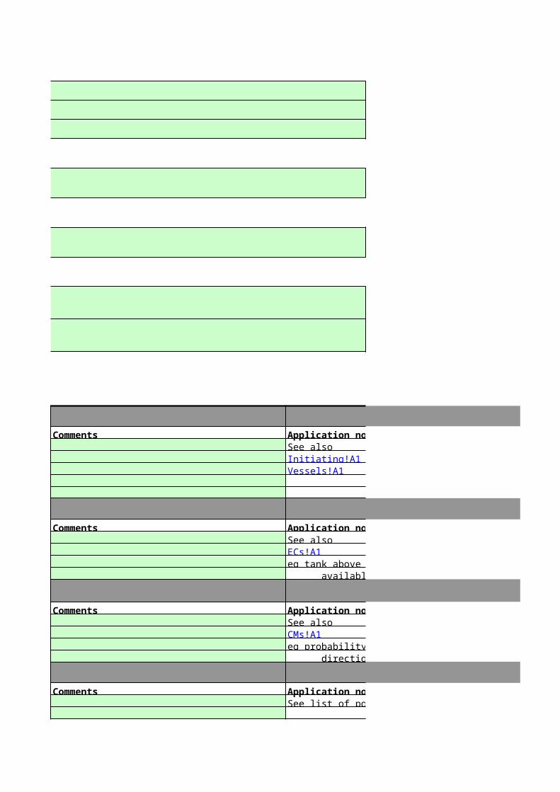
Comments Application notesSee also
Comments Application notesSee also
eg tank above a certain level, disposal plant not available, two pumps running
Comments Application notesSee also
eg probability of person present, fatal injury, wind direction, probability of ignition, etc
Comments Application notesSee list of possible devices / systems:
Initiating!A1Vessels!A1
ECs!A1
CMs!A1
Comments Application notes
Should not be given numberical credit; record only
Notes
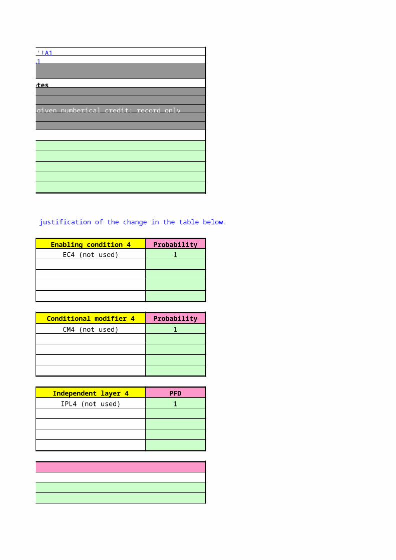
Overtype the probability value to 0, if the consideration does not apply to this initiating cause. It will then show in red. Place justification of the change in the table below.
Probability Enabling condition 3 Probability Enabling condition 4
1 EC3 (not used) 1 EC4 (not used)
1 EC3 (not used) 1 EC4 (not used)
1 EC3 (not used) 1 EC4 (not used)
1 EC3 (not used) 1 EC4 (not used)
1 EC3 (not used) 1 EC4 (not used)
Probability Conditional modifier 3 Probability Conditional modifier 4
1 CM3 (not used) 1 CM4 (not used)
1 CM3 (not used) 1 CM4 (not used)
1 CM3 (not used) 1 CM4 (not used)
1 CM3 (not used) 1 CM4 (not used)
1 CM3 (not used) 1 CM4 (not used)
PFD Independent layer 3 PFD Independent layer 4
1 IPL3 (not used) 1 IPL4 (not used)
1 IPL3 (not used) 1 IPL4 (not used)
1 IPL3 (not used) 1 IPL4 (not used)
1 IPL3 (not used) 1 IPL4 (not used)
1 IPL3 (not used) 1 IPL4 (not used)
Justification of any changes made to the data in the matrix
Reason
LoP candidates'!A1Non-SIS LoP'!A1
Target frequencies (from TOR sheet)Broadly acceptable
0.0001
0.000100
10000
SIL 5
Description
Broadly acceptable
Not able
Cells used by spreadsheet
Cat 1
Cat 2
Cat 3
Cat 4
Cat 5
Bursting disk See Intro
Relief valve See Intro
BPCS 0
SIL1 system 1
SIL2 system 2
SIL3 system 3
SIL4 system 4
Other
None
Environment
Application notesSee also
Application notesSee also
eg tank above a certain level, disposal plant not available, two pumps running
Application notesSee also
eg probability of person present, fatal injury, wind direction, probability of ignition, etc
Application notesSee list of possible devices / systems:
Personnel safety
Production and equipment
Application notes
Should not be given numberical credit; record only
Notes
Probability
1
1
1
1
1
Probability
1
1
1
1
1
PFD
1
1
1
1
1
Justification of any changes made to the data in the matrix
Reason
3
Description
Enabling conditions
Description Probability1.0
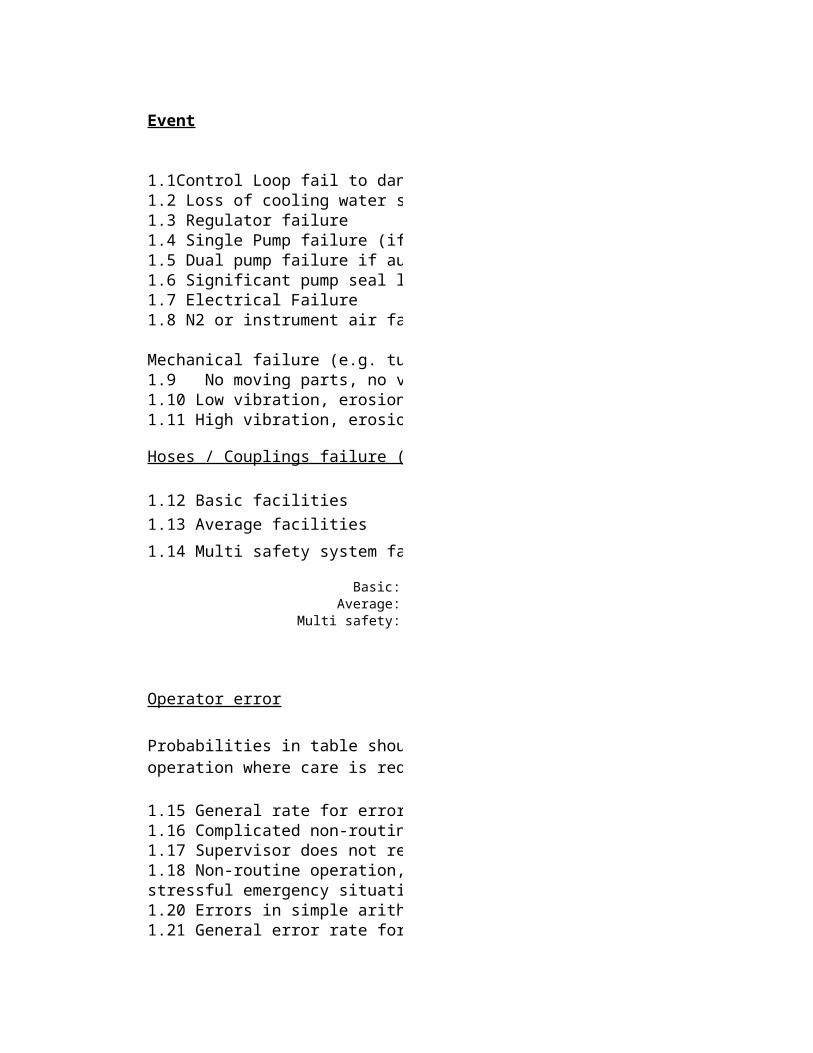
Event
1.1Control Loop fail to danger1.2 Loss of cooling water supply1.3 Regulator failure1.4 Single Pump failure (if no MTBF data available)1.5 Dual pump failure if autostart and run status provided1.6 Significant pump seal leak1.7 Electrical Failure1.8 N2 or instrument air failure
Mechanical failure (e.g. tube rupture, bellows failure, etc.)1.9 No moving parts, no vibration, erosion, corrosion1.10 Low vibration, erosion, corrosion1.11 High vibration, erosion, corrosion
1.15 General rate for errors involving very high stress levels1.16 Complicated non-routine task, with stress1.17 Supervisor does not recognise the operation’s error1.18 Non-routine operation, with other duties at the same time
1.20 Errors in simple arithmetic with self-checking1.21 General error rate for oral communication
1.23 Operator fails to act correctly after the first few hours in a high-stress scenario1.24 General error of omission1.25 Error in a routine operation where care is required
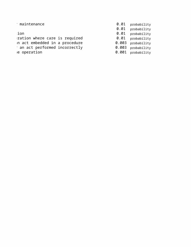
Probabilities in table should be multiplied by the number of opportunities, e.g. Error in routine operation where care is required when carried out daily = 0.001/opportunity * 365 opportunities / yr = 0.37/yr.
situation
after maintenance
1.26 Error of omission of an act embedded in a procedure1.27 General error rate for an act performed incorrectly1.28 Error in simple routine operation
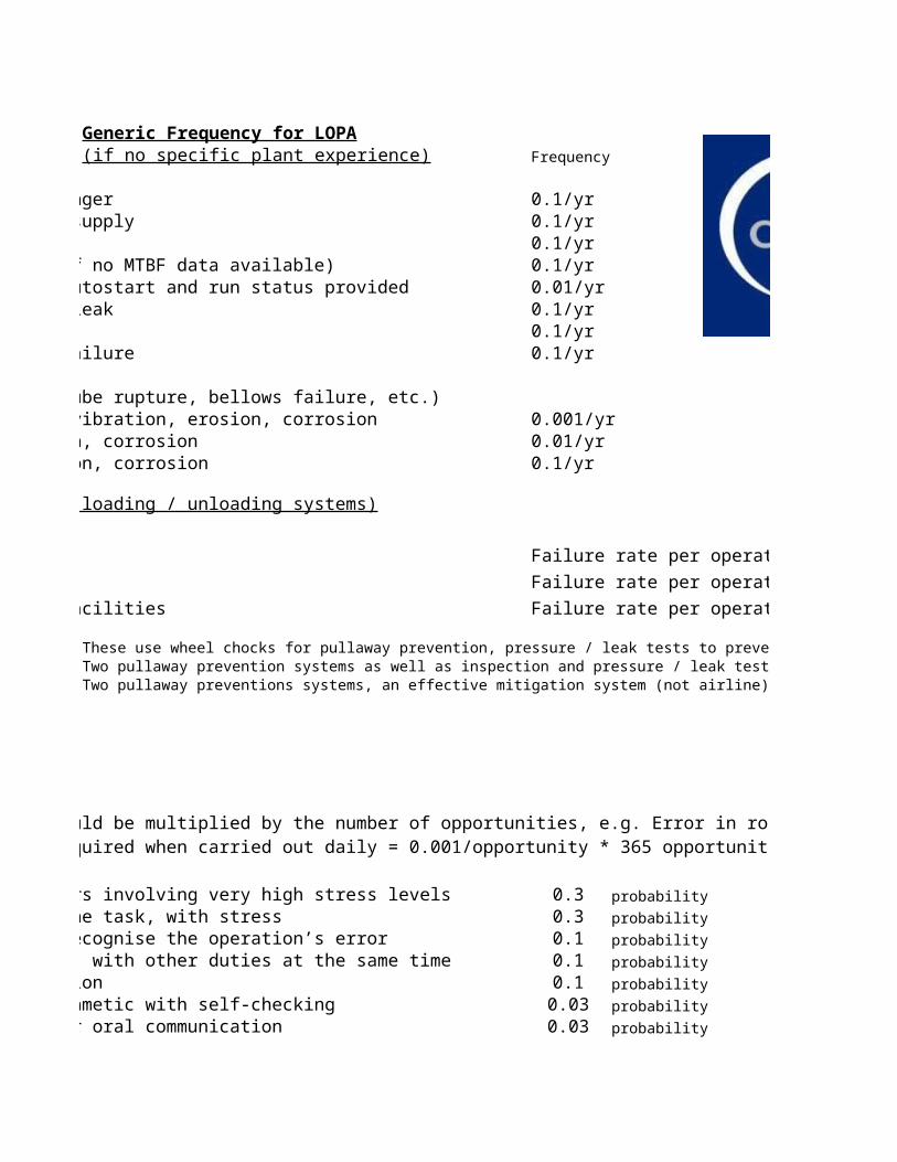
Generic Frequency for LOPA(if no specific plant experience) Frequency
0.1/yr0.1/yr0.1/yr
1.4 Single Pump failure (if no MTBF data available) 0.1/yr1.5 Dual pump failure if autostart and run status provided 0.01/yr
0.1/yr0.1/yr0.1/yr
Mechanical failure (e.g. tube rupture, bellows failure, etc.)1.9 No moving parts, no vibration, erosion, corrosion 0.001/yr1.10 Low vibration, erosion, corrosion 0.01/yr1.11 High vibration, erosion, corrosion 0.1/yr
These use wheel chocks for pullaway prevention, pressure / leak tests to prevent hose burst, and no pullaway mitigation.Two pullaway prevention systems as well as inspection and pressure / leak tests to prevent hose burst.Two pullaway preventions systems, an effective mitigation system (not airline) and pressure / leak tests to prevent hose burst.
1.15 General rate for errors involving very high stress levels 0.3 probability
1.16 Complicated non-routine task, with stress 0.3 probability
1.17 Supervisor does not recognise the operation’s error 0.1 probability
1.18 Non-routine operation, with other duties at the same time 0.1 probability
0.1 probability
1.20 Errors in simple arithmetic with self-checking 0.03 probability
1.21 General error rate for oral communication 0.03 probability
0.01 probability
1.23 Operator fails to act correctly after the first few hours in a high-stress scenario 0.01 probability
1.24 General error of omission 0.01 probability
1.25 Error in a routine operation where care is required 0.01 probability
Failure rate per operation 40 x 10-6
Failure rate per operation 4 x 10⁻⁶
Failure rate per operation 0.2 x 10⁻⁶
Probabilities in table should be multiplied by the number of opportunities, e.g. Error in routine operation where care is required when carried out daily = 0.001/opportunity * 365 opportunities / yr = 0.37/yr.
1.26 Error of omission of an act embedded in a procedure 0.003 probability
1.27 General error rate for an act performed incorrectly 0.003 probability
1.28 Error in simple routine operation 0.001 probability
From CCPS book
These use wheel chocks for pullaway prevention, pressure / leak tests to prevent hose burst, and no pullaway mitigation.
Two pullaway preventions systems, an effective mitigation system (not airline) and pressure / leak tests to prevent hose burst.
Probabilities in table should be multiplied by the number of opportunities, e.g. Error in routine operation where care is required when
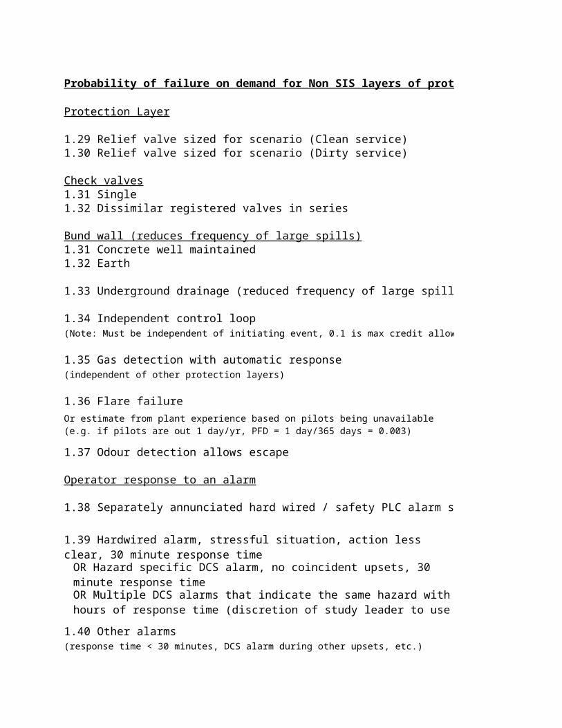
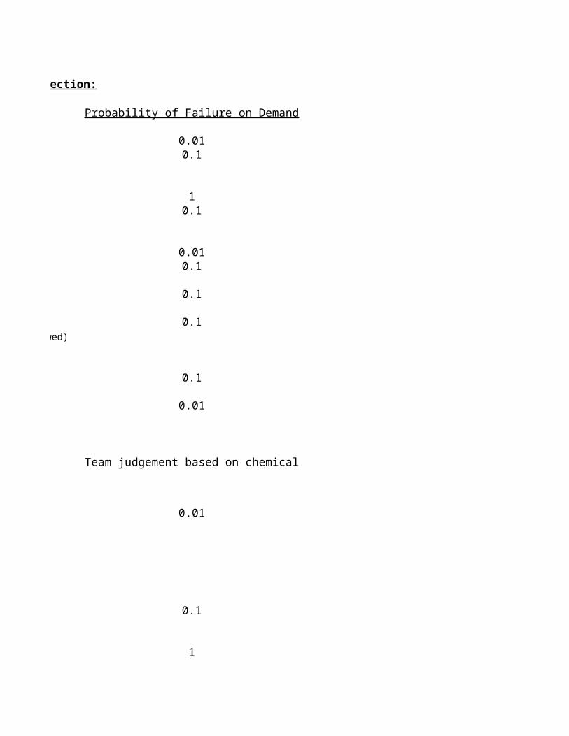
Probability of failure on demand for Non SIS layers of protection:
Protection Layer
1.29 Relief valve sized for scenario (Clean service)1.30 Relief valve sized for scenario (Dirty service)
Check valves1.31 Single1.32 Dissimilar registered valves in series
Bund wall (reduces frequency of large spills)1.31 Concrete well maintained1.32 Earth
1.33 Underground drainage (reduced frequency of large spill)
1.34 Independent control loop(Note: Must be independent of initiating event, 0.1 is max credit allowed)
1.35 Gas detection with automatic response(independent of other protection layers)
1.36 Flare failure
1.37 Odour detection allows escape
Operator response to an alarm
1.38 Separately annunciated hard wired / safety PLC alarm specific to haz
1.40 Other alarms(response time < 30 minutes, DCS alarm during other upsets, etc.)
Or estimate from plant experience based on pilots being unavailable (e.g. if pilots are out 1 day/yr, PFD = 1 day/365 days = 0.003)
1.39 Hardwired alarm, stressful situation, action less clear, 30 minute response time
OR Hazard specific DCS alarm, no coincident upsets, 30 minute response timeOR Multiple DCS alarms that indicate the same hazard with hours of response time (discretion of study leader to use 0.01)
From CCPS book
Probability of Failure on Demand
0.010.1
10.1
0.010.1
0.1
0.1
0.1
0.01
Team judgement based on chemical
0.01
0.1
1
From CCPS book
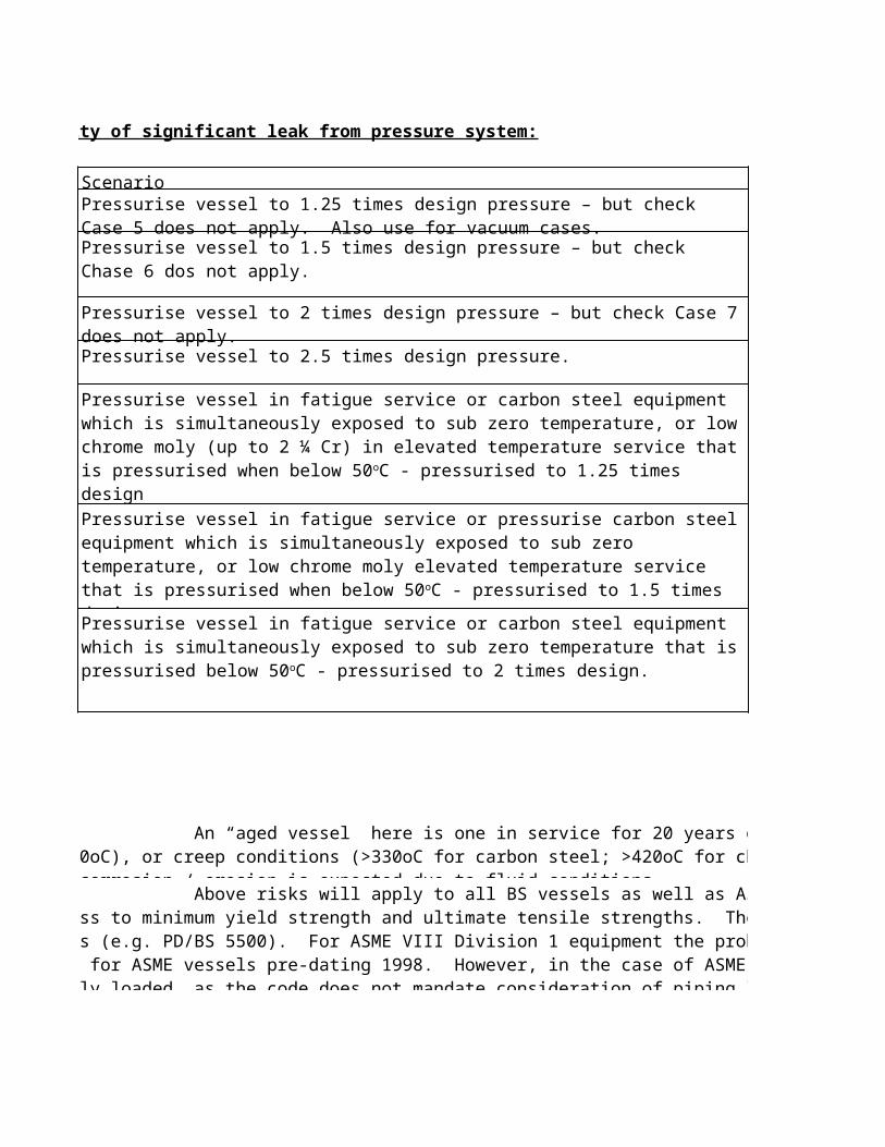
Probability of significant leak from pressure system:
Case1.41
1.42
1.43
1.44
1.45
1.46
1.47
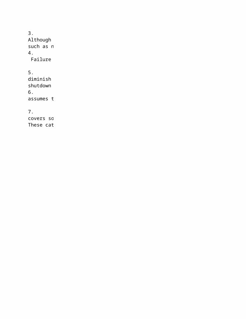
Notes:
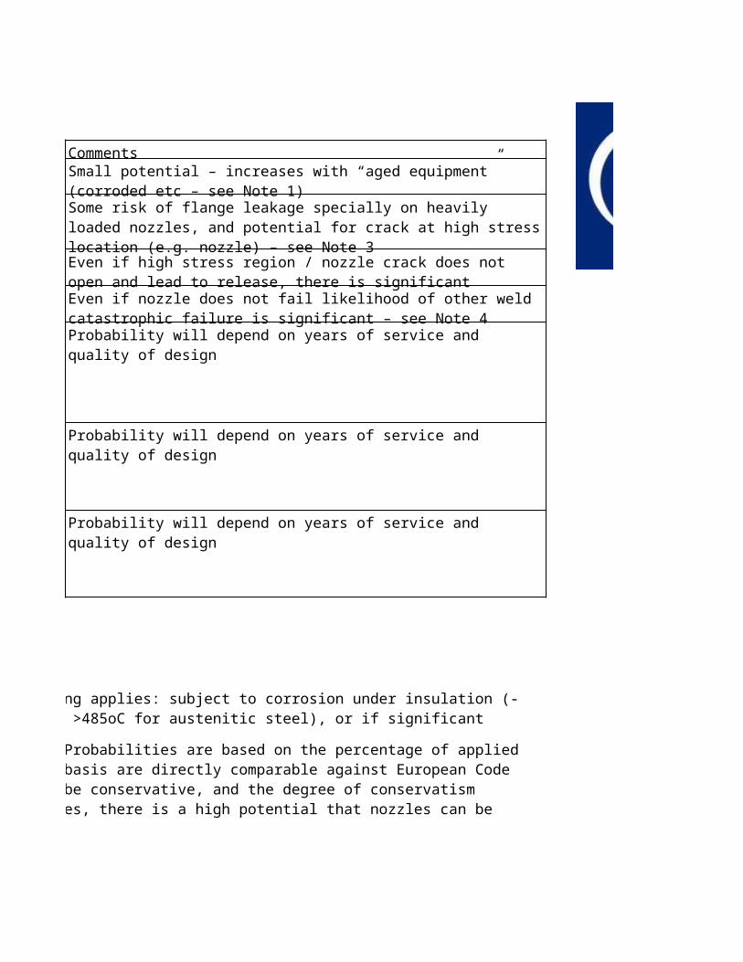
1. An “aged vessel” here is one in service for 20 years of longer and where the following applies: subject to corrosion under insulation (-5oC to 200oC), or creep conditions (>330oC for carbon steel; >420oC for chrome moly steels up to 12% Cr; >485oC for austenitic steel), or if significant internal corrosion / erosion is expected due to fluid conditions.
2. Above risks will apply to all BS vessels as well as ASME vessels built after 1998. Probabilities are based on the percentage of applied hoop stress to minimum yield strength and ultimate tensile strengths. The probabilities quoted on this basis are directly comparable against European Code approaches (e.g. PD/BS 5500). For ASME VIII Division 1 equipment the probabilities quoted with tend to be conservative, and the degree of conservatism increases for ASME vessels pre-dating 1998. However, in the case of ASME vessels, particularly older ones, there is a high potential that nozzles can be excessively loaded, as the code does not mandate consideration of piping loads onto nozzles.
3. This level of pressure (1.5 times design) will generate bulk membrane (hoop) stresses close to minimum yield strength in European code vessels. Although failure of the membrane from a few applications is unlikely, there is a risk of opening a significant crack in highly stressed and localised regions such as nozzles.
4. This level of pressure (2.5 times design) will generate bulk membrane (hoop) stresses close to ultimate tensile strength in European code vessels. Failure could almost be guaranteed to European code vessels, and failure could well be significant or catastrophic.
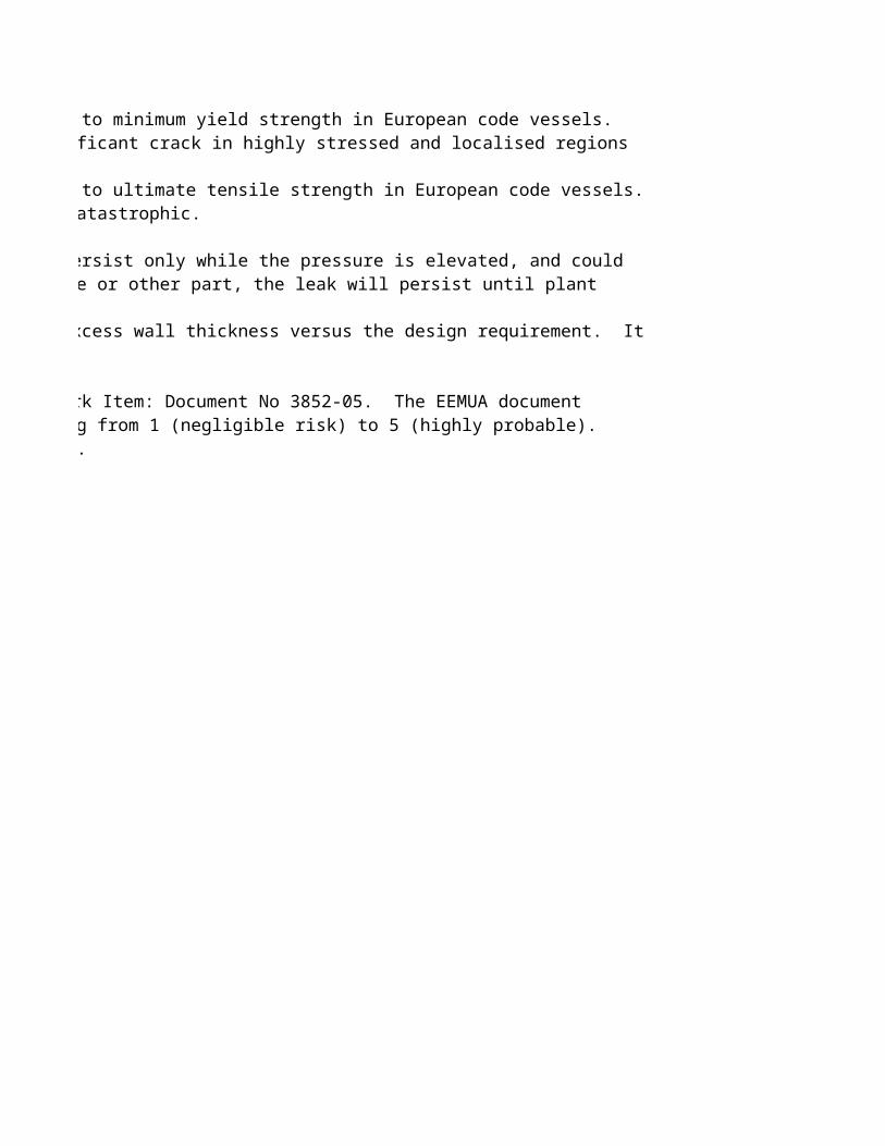
5. In the event of only a flange leak (1.5 to 2 times design pressure) the leak is likely to persist only while the pressure is elevated, and could diminish or cease when pressure returns below design pressure, whereas in the case of a crack in a nozzle or other part, the leak will persist until plant shutdown / isolation.
6. These risk factors take no account of the fact that equipment may have been supplied with excess wall thickness versus the design requirement. It assumes the worst case, and that only nominal corrosion allowances have been applied.
7. This document refer to EEMUA Pressure Vessels Committee: Risk Based Mechanical Integrity Work Item: Document No 3852-05. The EEMUA document covers some of these issues, and relates to likelihood of failure in terms of Categories 1 to 5, ranging from 1 (negligible risk) to 5 (highly probable). These categories in turn derive from API Publication 581: Base Resource Document – Risk Based Inspection.
Probability of significant leak from pressure system:
Scenario
Pressurise vessel to 2.5 times design pressure.
Pressurise vessel to 1.25 times design pressure – but check Case 5 does not apply. Also use for vacuum cases.Pressurise vessel to 1.5 times design pressure – but check Chase 6 dos not apply.
Pressurise vessel to 2 times design pressure – but check Case 7 does not apply.
Pressurise vessel in fatigue service or carbon steel equipment which is simultaneously exposed to sub zero temperature, or low chrome moly (up to 2 ¼ Cr) in elevated temperature service that is pressurised when below 50oC - pressurised to 1.25 times design
Pressurise vessel in fatigue service or pressurise carbon steel equipment which is simultaneously exposed to sub zero temperature, or low chrome moly elevated temperature service that is pressurised when below 50oC - pressurised to 1.5 times design.
Pressurise vessel in fatigue service or carbon steel equipment which is simultaneously exposed to sub zero temperature that is pressurised below 50oC - pressurised to 2 times design.
1. An “aged vessel” here is one in service for 20 years of longer and where the following applies: subject to corrosion under insulation (-5oC to 200oC), or creep conditions (>330oC for carbon steel; >420oC for chrome moly steels up to 12% Cr; >485oC for austenitic steel), or if significant internal corrosion / erosion is expected due to fluid conditions.
2. Above risks will apply to all BS vessels as well as ASME vessels built after 1998. Probabilities are based on the percentage of applied hoop stress to minimum yield strength and ultimate tensile strengths. The probabilities quoted on this basis are directly comparable against European Code approaches (e.g. PD/BS 5500). For ASME VIII Division 1 equipment the probabilities quoted with tend to be conservative, and the degree of conservatism increases for ASME vessels pre-dating 1998. However, in the case of ASME vessels, particularly older ones, there is a high potential that nozzles can be excessively loaded, as the code does not mandate consideration of piping loads onto nozzles.
3. This level of pressure (1.5 times design) will generate bulk membrane (hoop) stresses close to minimum yield strength in European code vessels. Although failure of the membrane from a few applications is unlikely, there is a risk of opening a significant crack in highly stressed and localised regions such as nozzles.
4. This level of pressure (2.5 times design) will generate bulk membrane (hoop) stresses close to ultimate tensile strength in European code vessels. Failure could almost be guaranteed to European code vessels, and failure could well be significant or catastrophic.
5. In the event of only a flange leak (1.5 to 2 times design pressure) the leak is likely to persist only while the pressure is elevated, and could diminish or cease when pressure returns below design pressure, whereas in the case of a crack in a nozzle or other part, the leak will persist until plant shutdown / isolation.
6. These risk factors take no account of the fact that equipment may have been supplied with excess wall thickness versus the design requirement. It assumes the worst case, and that only nominal corrosion allowances have been applied.
7. This document refer to EEMUA Pressure Vessels Committee: Risk Based Mechanical Integrity Work Item: Document No 3852-05. The EEMUA document covers some of these issues, and relates to likelihood of failure in terms of Categories 1 to 5, ranging from 1 (negligible risk) to 5 (highly probable). These categories in turn derive from API Publication 581: Base Resource Document – Risk Based Inspection.
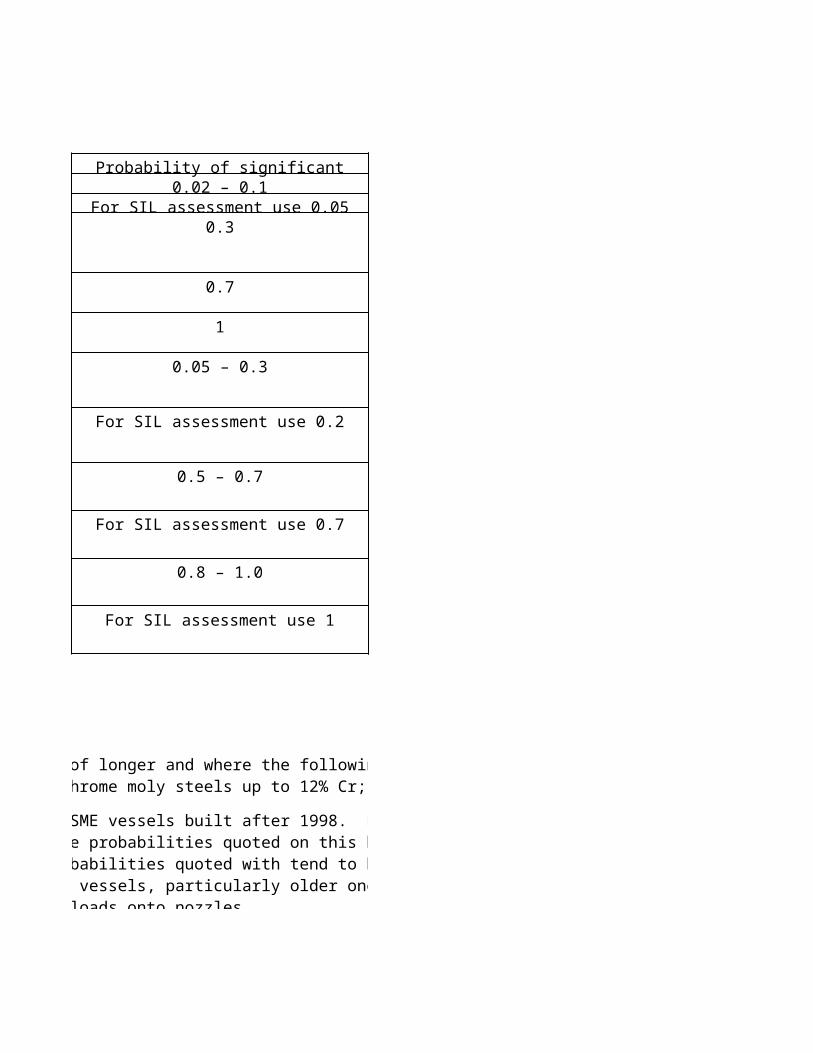
Probability of significant release0.02 – 0.1
For SIL assessment use 0.050.3
0.7
1
0.05 – 0.3
For SIL assessment use 0.2
0.5 – 0.7
For SIL assessment use 0.7
0.8 – 1.0
For SIL assessment use 1
1. An “aged vessel” here is one in service for 20 years of longer and where the following applies: subject to corrosion under insulation (-5oC to 200oC), or creep conditions (>330oC for carbon steel; >420oC for chrome moly steels up to 12% Cr; >485oC for austenitic steel), or if significant internal corrosion / erosion is expected due to fluid conditions.
2. Above risks will apply to all BS vessels as well as ASME vessels built after 1998. Probabilities are based on the percentage of applied hoop stress to minimum yield strength and ultimate tensile strengths. The probabilities quoted on this basis are directly comparable against European Code approaches (e.g. PD/BS 5500). For ASME VIII Division 1 equipment the probabilities quoted with tend to be conservative, and the degree of conservatism increases for ASME vessels pre-dating 1998. However, in the case of ASME vessels, particularly older ones, there is a high potential that nozzles can be excessively loaded, as the code does not mandate consideration of piping loads onto nozzles.
This level of pressure (1.5 times design) will generate bulk membrane (hoop) stresses close to minimum yield strength in European code vessels. Although failure of the membrane from a few applications is unlikely, there is a risk of opening a significant crack in highly stressed and localised regions such as nozzles.
This level of pressure (2.5 times design) will generate bulk membrane (hoop) stresses close to ultimate tensile strength in European code vessels. Failure could almost be guaranteed to
In the event of only a flange leak (1.5 to 2 times design pressure) the leak is likely to persist only while the pressure is elevated, and could diminish or cease when pressure returns below design pressure, whereas in the case of a crack in a nozzle or other part, the leak will persist until plant shutdown / isolation.
These risk factors take no account of the fact that equipment may have been supplied with excess wall thickness versus the design requirement. It assumes the worst case, and that only
This document refer to EEMUA Pressure Vessels Committee: Risk Based Mechanical Integrity Work Item: Document No 3852-05. The EEMUA document covers some of these issues, and relates to likelihood of failure in terms of Categories 1 to 5, ranging from 1 (negligible risk) to 5 (highly probable). These categories in turn derive from API Publication 581: Base Resource Document
Comments
Probability will depend on years of service and quality of design
Probability will depend on years of service and quality of design
Probability will depend on years of service and quality of design
Small potential – increases with “aged equipment” (corroded etc – see Note 1)Some risk of flange leakage specially on heavily loaded nozzles, and potential for crack at high stress location (e.g. nozzle) – see Note 3
Even if high stress region / nozzle crack does not open and lead to release, there is significant likelihood of flange leakEven if nozzle does not fail likelihood of other weld catastrophic failure is significant – see Note 4
1. An “aged vessel” here is one in service for 20 years of longer and where the following applies: subject to corrosion under insulation (-5oC to 200oC), or creep conditions (>330oC for carbon steel; >420oC for chrome moly steels up to 12% Cr; >485oC for austenitic steel), or if significant internal corrosion / erosion is expected due to fluid conditions.
2. Above risks will apply to all BS vessels as well as ASME vessels built after 1998. Probabilities are based on the percentage of applied hoop stress to minimum yield strength and ultimate tensile strengths. The probabilities quoted on this basis are directly comparable against European Code approaches (e.g. PD/BS 5500). For ASME VIII Division 1 equipment the probabilities quoted with tend to be conservative, and the degree of conservatism increases for ASME vessels pre-dating 1998. However, in the case of ASME vessels, particularly older ones, there is a high potential that nozzles can be excessively loaded, as the code does not mandate consideration of piping loads onto nozzles.
This level of pressure (1.5 times design) will generate bulk membrane (hoop) stresses close to minimum yield strength in European code vessels. Although failure of the membrane from a few applications is unlikely, there is a risk of opening a significant crack in highly stressed and localised regions such as nozzles.
This level of pressure (2.5 times design) will generate bulk membrane (hoop) stresses close to ultimate tensile strength in European code vessels. Failure could almost be guaranteed to
In the event of only a flange leak (1.5 to 2 times design pressure) the leak is likely to persist only while the pressure is elevated, and could diminish or cease when pressure returns below design pressure, whereas in the case of a crack in a nozzle or other part, the leak will persist until plant shutdown / isolation.
These risk factors take no account of the fact that equipment may have been supplied with excess wall thickness versus the design requirement. It assumes the worst case, and that only
This document refer to EEMUA Pressure Vessels Committee: Risk Based Mechanical Integrity Work Item: Document No 3852-05. The EEMUA document covers some of these issues, and relates to likelihood of failure in terms of Categories 1 to 5, ranging from 1 (negligible risk) to 5 (highly probable). These categories in turn derive from API Publication 581: Base Resource Document
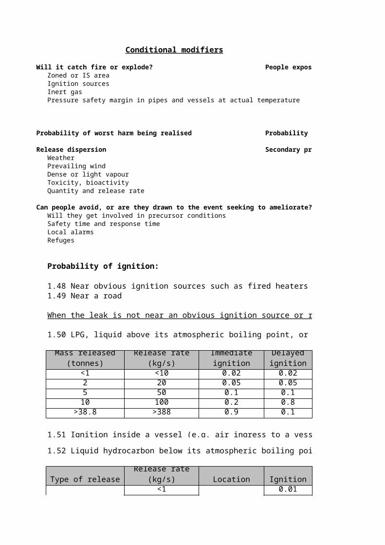
Conditional modifiers
Will it catch fire or explode? People exposureZoned or IS area Probability of being in the danger areaIgnition sourcesInert gasPressure safety margin in pipes and vessels at actual temperature
Probability of worst harm being realised Probability of leak (/problem) being undetected
Release dispersion Secondary protectionWeather BuildingsPrevailing wind Blast wallsDense or light vapour TopographyToxicity, bioactivityQuantity and release rate
Can people avoid, or are they drawn to the event seeking to ameliorate?Will they get involved in precursor conditionsSafety time and response timeLocal alarmsRefuges
Probability of ignition:
1.48 Near obvious ignition sources such as fired heaters 11.49 Near a road 0.5
When the leak is not near an obvious ignition source or road:
1.50 LPG, liquid above its atmospheric boiling point, or material above its flash point released at he
1.52 Liquid hydrocarbon below its atmospheric boiling point and released near ground level. No obvious ignition sources.
Type of release Release rate (kg/s) Location Ignition No ignition
Liquid<1
General0.01 0.99
Mass released (tonnes)
Immediate ignition
Delayed ignition
1.51 Ignition inside a vessel (e.g. air ingress to a vessel by operation of vacuum valves or landing a floating roof tank) 0.01 due to absence of ignition sources and fuel rich.
Liquid 1 – 50 General 0.03 0.97>50 0.08 0.92
Person present
11.54 Within the plant structure 0.11.55 Normally unoccupied area (e.g. tank farms) 0.01
Note: Team can also estimate probability directly if information available (e.g. 1 hour operator tour of area every shift = 1 hours / 12 hours = 0.08).
Wind Direction 1.56 Wind in prevailing direction 0.71.57 Wind other than prevailing direction 0.3
Guidance on Consequence Categories:
1.53 Large release, normally occupied area, operator present during the hazardous activity or local resident (off-site potential)
Choosing the consequence category requires some judgement from the LOPA leader in conjunction with the word model. The guidance below is very general and should be applied with care.1.58 For analysing safety consequences, a release of hydrocarbon below its boiling point would normally be considered a Category 3 consequence.1.59 A release of LPG, hydrocarbon above its atmospheric boiling point, or hydrocarbon above its flash point released at height with significant evaporation potential, would normally be considered Category 4 consequence. The size of the release would be The scenarios with very large released (large enough to have offsite fatality potential, or occupied building impact) would typically be covered in the COMAH reports.
Probability of being in the danger areaEmployees
Plant operatorsOther (maintenance etc)
VisitorsPublic
Probability of leak (/problem) being undetected
1.50 LPG, liquid above its atmospheric boiling point, or material above its flash point released at he
1.52 Liquid hydrocarbon below its atmospheric boiling point and released near ground level. No obvious ignition sources.
1.51 Ignition inside a vessel (e.g. air ingress to a vessel by operation of vacuum valves or landing
Note: Team can also estimate probability directly if information available (e.g. 1 hour operator tour of area every shift = 1 hours / 12 hours = 0.08).
Choosing the consequence category requires some judgement from the LOPA leader in conjunction with the word model. The guidance below is very general and should be applied with 1.58 For analysing safety consequences, a release of hydrocarbon below its boiling point would 1.59 A release of LPG, hydrocarbon above its atmospheric boiling point, or hydrocarbon above its flash point released at height with significant evaporation potential, would normally be considered The scenarios with very large released (large enough to have offsite fatality potential, or occupied
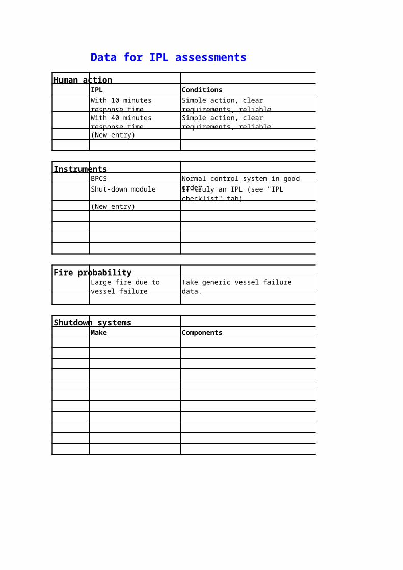
Data for IPL assessments
Human actionIPL Conditions PFD
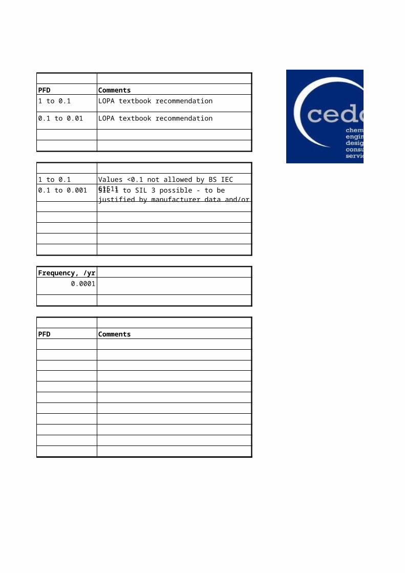
1 to 0.1
0.1 to 0.01
(New entry)
InstrumentsBPCS Normal control system in good order 1 to 0.1
Shut-down module If truly an IPL (see "IPL checklist" tab) 0.1 to 0.001
SIL 1 to SIL 3 possible - to be justified by manufacturer data and/or calculation
IPL checklist
Name of IPLDescription
Is it an IPL? Judgement
Does it detect the condition?
Does it decide to take action?
Does it deflect the undesired event?
Is it enough?
Is it big enough?
Is it fast enough?
Is it strong enough?
Is it reliable?
Can it be tested and be auditable?
Is it independent?
IPL checksConsider the following three "D" factors to help decide if a safeguard is an IPL:
DetectDecideDeflect
Then consider the following three "E" factors to help decide if the safegualrd will be an effective IPL:Big enough?Fast enough?Strong enough?
Finally, ensure that the safeguard is INDEPENDENT of the initiating event and all the other IPLs so that it can be assumed to work every time (assuming it is operational)
Can any circumstances arise that will reduce its effectiveness?
Of the initiating event and any enabling event?
Of any other device, system or action that is already credited with being an IPL?
Note - Standards only allows one credit for the BPCS. Two are allowed under certain circumstances, and should not credit a PFD better than 0.1 unless carefully
Copy this sheet / table as needed for multiple IPLs
Comments
Consider the following three "D" factors to help decide if a safeguard is an IPL:Most IPLs detect a condition that is leading to the loss scenarioMany IPLs make a decision whether or not to take actionAll IPLs must deflect the loss event by preventing it
Then consider the following three "E" factors to help decide if the safegualrd will be an effective IPL:
Finally, ensure that the safeguard is INDEPENDENT of the initiating event and all the other IPLs so that it can be assumed to work every time (assuming it is operational)
Note - Standards only allows one credit for the BPCS. Two are allowed under certain circumstances, and should not credit a PFD better than 0.1 unless carefully
Finally, ensure that the safeguard is INDEPENDENT of the initiating event and all the other IPLs so that it can be assumed to work every time (assuming it is operational)
Preparation - getP&IDsCause & effect diagramsProject approved SIL procedureProject TORGeneral process descriptionProject forms for
SIL / LoPA assessmentRisk graph if neededLoPA analysisMeeting records
List of peopleConfirmation of area to be covered
Preparation - doHighlight trips and ESDs on P&IDs working copyReview any previous ones on the projectAgree recording style with SecretaryFind items to be considered on Control Sheet
Meeting startWhat has gone before; current meeting aimsReview of forms to be usedReview of recording procedureEmphasise all team's names are signed to records, must point out any disagreements before item is savedRun though an assessmentEmphasis BPCS limitationClarify control systems in use (PESS, PLC, DCS, etc)


![10 LOPA [Compatibility Mode]](https://static.documents.pub/doc/80x56/577c7c701a28abe0549a989e/10-lopa-compatibility-mode.jpg)


