206w w w . a d c . c o m • + 1 - 9 5 2 - 9 3 8 - 8 0 8 0 • 1 - 8 0 0 - 3 6 6 - 3 8 9 1
Co
pp
er C
able
Man
agem
ent
Solu
tio
ns
Copper Cable Management SolutionsEthernet Distribution Frame
7' EIA 19" UEF Zone 4 Rack
Glide Cable Management Adapter
PowerWorx® Power Distribution Panel
2RU Horizontal Cable Manager
Media Converter
Fiber Management Tray
48-Port Category 5e Panel
8" Glide Cable Management
Bottom Crossover Trough
ADC’s Ethernet Distribution Frame (EDF) forms a central patching location between active Ethernet network elements. By creating a centralized craft interface for adds, upgrades, and rearrangements on Ethernet equipment, the EDF enables change without service disruptions. This central patching location provides a logical and easy-to-manage infrastructure due to two design characteristics:
• All network elements have permanent equipment cable connections that are, once terminated, never handled again.
• All changes, circuit rerouting, upgrades, maintenance and other activities are accomplished using semi-permanent patch cords on the front of the EDF cross-connect bay.
207w w w . a d c . c o m • + 1 - 9 5 2 - 9 3 8 - 8 0 8 0 • 1 - 8 0 0 - 3 6 6 - 3 8 9 1
Co
pp
er C
able
Man
agem
ent
Solu
tio
ns
5/
08
•
1
02
09
4A
E
Tr
ueN
et® S
tru
ctu
red
Cab
ling
Copper Cable Management SolutionsVertical and Horizontal Cable Management
1
1
2
2
Upper and lower crossover managers with vertical cable managers enable easy,
intuitive cable routing.
Glide Cable Manager
Features
• Integrated front, rear, horizontal, and vertical cable management
• Patented rib cage design eliminates horizontal support trays and bars
• Supports up to 912 ports on a single rack
• Built-in bend radius protection ensures network integrity
• Designed for quick and easy moves, adds, and changes
• Optional slack managers available for 6-, 8-, 10-, and 12-inch widths
• Fits standard EIA rack with three-inch channel
• Used for single rack or as inter-rack unit
• Optional crossover troughs and horizontal cable managers available
• Optional EIA-standard horizontal support bars available
6/
10
•
1
02
09
4A
E
Tr
ueN
et® S
tru
ctu
red
Cab
ling
208w w w . a d c . c o m • + 1 - 9 5 2 - 9 3 8 - 8 0 8 0 • 1 - 8 0 0 - 3 6 6 - 3 8 9 1
Co
pp
er C
able
Man
agem
ent
Solu
tio
ns
Copper Cable Management SolutionsVertical and Horizontal Cable Management
Description
Glide cable manager, vertical mount—to equip both sides of a 7-foot rack, order two Glide Cable Manager units 6", front only, without slack manager 6", front only, with slack manager 6", without slack manager 8", without slack manager 10", without slack manager 12", without slack manager 6", with slack manager 8", with slack manager 10", with slack manager 12", with slack managerCrossover trough, 2RU Crossover trough, 4RU
Hinged black metal cover kits:to equip both sides of a 7' rack (front and back), order 2 cover kits. 41" x 6" 41" x 8" 41" x 10" 41" x 12"
Hinged black metal cover kits:to equip both sides of a 7' rack (front only), order 2 cover kits. These covers are for Glide Cable Managers ADCCMVIB06F-2 and ADCCMVIBS06F-2 only. 41" x 6", two per pack
Note: Stabilizer used at end of lineup for each Vertical Integrator section.
Description
7' equipment racksSelf-assembly aluminum relay rack, 3" channel Black Brushed aluminum Welded steel relay rack, 3" channel, blackWelded steel relay rack, Zone 4 rated, black Unequal flange Network unequal flange
O r d e r i n g I n f o r m a t i o n
Catalog Number
ADCRACKBLK73 ADCRACKMF73 ADCRACKBLK73WS
ADCRACKBLK73UE-75 PWUEF-7ERN-BLK
Spacing
19" EIA19" EIA19" EIA
19" EIA23" EIA
Glide Cable Manager
6/
10
•
1
02
09
4A
E
Tr
ueN
et® S
tru
ctu
red
Cab
ling
210w w w . a d c . c o m • + 1 - 9 5 2 - 9 3 8 - 8 0 8 0 • 1 - 8 0 0 - 3 6 6 - 3 8 9 1
Co
pp
er C
able
Man
agem
ent
Solu
tio
ns
Copper Cable Management SolutionsVertical and Horizontal Cable Management
Finger Duct Front and Rear Managers
Finger Duct Front Managers
These large capacity managers provide ample room for organizing both incoming cables and patch cords with modular patch panels. They fit on a standard EIA 19" equipment rack. The managers are made of UL 94V-0 plastic and include snap-on covers.
ADC's Front Managers are great for organizing patch cords with modular patch panels. They fit on a standard EIA 19" equipment rack. The managers are made of UL 94V-0 plastic and include a snap-on cover.
O r d e r i n g I n f o r m a t i o n
O r d e r i n g I n f o r m a t i o n
Description Dimensions (HxWxD) Catalog Number
Description Dimensions (HxWxD) Catalog Number
1.5"x 3" Front Manager and 1"x 4" Rear Manager, Pack Quantity: 1
3"x 3" Front Manager and 2"x 4" Rear Manager, Pack Quantity: 1
3"x 3" Front Manager and 3"x 4" Rear Manager, Pack Quantity: 1
1.5"x 3" Front Manager, Pack Quantity: 1
3"x 3" Front Manager, Pack Quantity: 1
1.75" x 19" x 3.5" (44.45mm x 482.6mm x 88.9mm)
3.5" x 19" x 3.5" (88.9mm x 482.6mm x 88.9mm)
3.5" x 19" x 4.5" (88.9mm x 482.6mm x 114.3mm)
1.75" x 19" x 3.5" (44.45mm x 482.6mm x 88.9mm)
3.5" x 19" x 3.5" (88.9mm x 482.6mm x 88.9mm)
6652 2 153-14
6652 2 330-24
6652 2 330-34
6652 2 153-00
6652 2 330-00
Finger Duct Front Manager, 1.5"x 3"
Finger Duct Front and Rear Manager, 3"x 3" Front and 3"x 4" Rear
6/
10
•
1
02
09
4A
E
Tr
ueN
et® S
tru
ctu
red
Cab
ling
211w w w . a d c . c o m • + 1 - 9 5 2 - 9 3 8 - 8 0 8 0 • 1 - 8 0 0 - 3 6 6 - 3 8 9 1
Co
pp
er C
able
Man
agem
ent
Solu
tio
ns
Copper Cable Management SolutionsVertical and Horizontal Cable Management
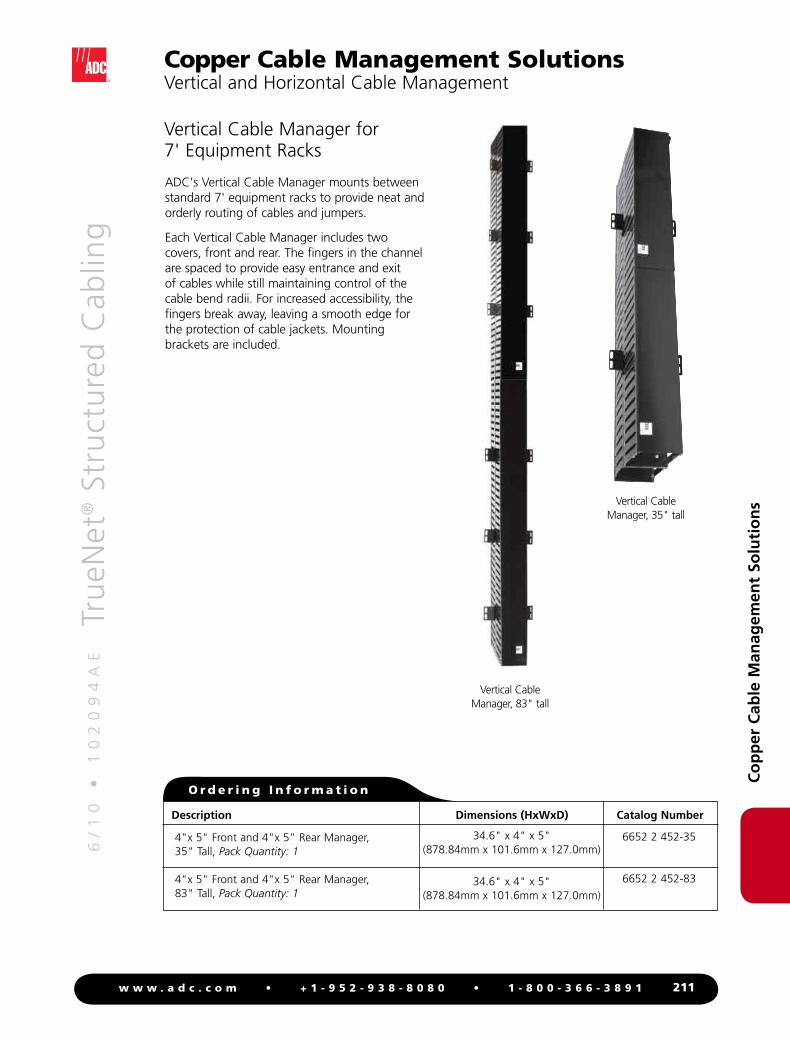
Vertical Cable Manager for 7' Equipment Racks
ADC's Vertical Cable Manager mounts between standard 7' equipment racks to provide neat and orderly routing of cables and jumpers.
Each Vertical Cable Manager includes two covers, front and rear. The fingers in the channel are spaced to provide easy entrance and exit of cables while still maintaining control of the cable bend radii. For increased accessibility, the fingers break away, leaving a smooth edge for the protection of cable jackets. Mounting brackets are included.
Vertical Cable Manager, 83" tall
Vertical Cable Manager, 35" tall
O r d e r i n g I n f o r m a t i o n
Description Dimensions (HxWxD) Catalog Number
4"x 5" Front and 4"x 5" Rear Manager, 35" Tall, Pack Quantity: 1
4"x 5" Front and 4"x 5" Rear Manager, 83" Tall, Pack Quantity: 1
34.6" x 4" x 5" (878.84mm x 101.6mm x 127.0mm)
34.6" x 4" x 5" (878.84mm x 101.6mm x 127.0mm)
6652 2 452-35
6652 2 452-83
6/
10
•
1
02
09
4A
E
Tr
ueN
et® S
tru
ctu
red
Cab
ling
212w w w . a d c . c o m • + 1 - 9 5 2 - 9 3 8 - 8 0 8 0 • 1 - 8 0 0 - 3 6 6 - 3 8 9 1
• Fit standard 19-, 23- and 35.5-inch equipment racks
• Mounting hardware and backboards available for either wall or rack mounting
• Wire management built-in, or available as accessories
• Most ADC blocks have a minimum of two mounting options
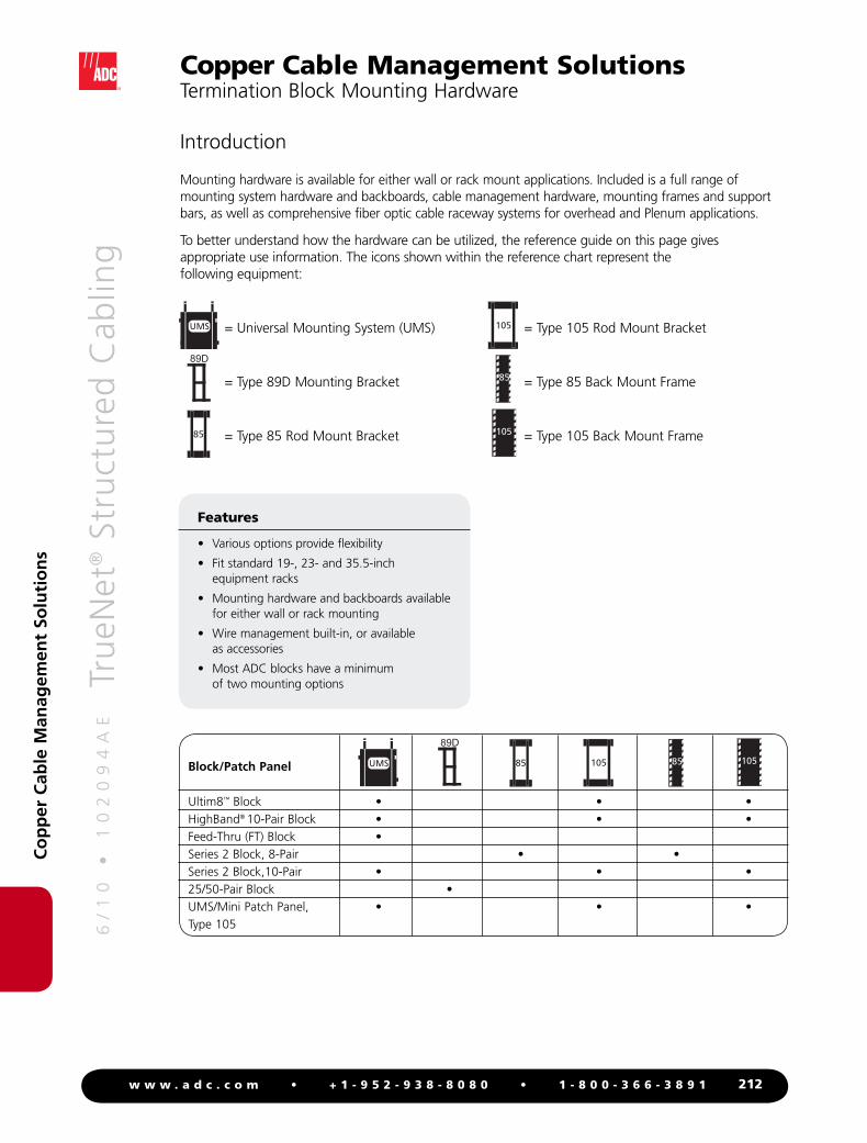
Mounting hardware is available for either wall or rack mount applications. Included is a full range of mounting system hardware and backboards, cable management hardware, mounting frames and support bars, as well as comprehensive fiber optic cable raceway systems for overhead and Plenum applications.
To better understand how the hardware can be utilized, the reference guide on this page gives appropriate use information. The icons shown within the reference chart represent the following equipment:
= Universal Mounting System (UMS) = Type 105 Rod Mount Bracket
= Type 89D Mounting Bracket = Type 85 Back Mount Frame
= Type 85 Rod Mount Bracket = Type 105 Back Mount Frame
The Universal Mounting System accepts Ultim8™, HighBand® 10, 10-pair Series 2, and 25-pair FT (Feed-Thru) blocks and UMS/Mini patch panels. It is a rugged, low cost, versatile alternative to traditional mounting systems. Besides providing a sturdy, easy-to-install interlinking foundation, the UMS features built-in wire and cable management, and convenient add-ons.
The mounting brackets interlink left-to-right and top-to-bottom to provide a foundation that is easy to install and easy to expand. The brackets are suitable for both rack and wall mount installations.
For fast installation, use the push rivets provided with the UMS backboard to attach the UMS brackets to the backboards.
O r d e r i n g I n f o r m a t i o n
Description Dimensions (HxWxD) Catalog Number
UMS Basic KitIncludes one pair of adjustable universal mounting brackets (holds up to 13 Ultim8 blocks and/or label holders), two horizontal wire managers, and appropriate screws and rivets. Typical installation holds 96 pairs using (12) 8-pair Ultim8 blocks (24-ports) and (1) Type 105 label holder. Kit mounts directly to a wall, or to an optional rack or wall mount backboard. Quantity: 1
UMS Basic Kit; Black
UMS Basic Kit; Gray
14.75" x 8.25 x 5.25"(374.7mm x 209.6mm x 133.4mm)
Universal Mounting System (UMS)
6657 2 165-40
6657 2 165-00
The UMS easily expands from the Type 105 position to the Type 160 position.
UMS In Type 105 position UMS In Type 160 position
6/
10
•
1
02
09
4A
E
Tr
ueN
et® S
tru
ctu
red
Cab
ling
214w w w . a d c . c o m • + 1 - 9 5 2 - 9 3 8 - 8 0 8 0 • 1 - 8 0 0 - 3 6 6 - 3 8 9 1
Universal Mounting System (UMS) Cable and Wire Managers
Vertical cable manager
Horizontal wire manager
19" equipment rack with three dual height backboards, each holding four Type 105 Universal Mounting Brackets and two vertical cable managers (1,152 pairs or 288 ports).
Connect here for Ultim8 blocks
Connect here for 25-pair FT blocks
Individual ribs on the vertical cable manager remove to provide additional room for routing patch cords or cables.
Ordering information follows on the next page
Tech TipWhen connecting two UMS brackets, use the inner slot for HighBand blocks or 10-pair Series 2 blocks (Type 105) and the outer slot for 25-pair FT blocks (Type 160).
6/
10
•
1
02
09
4A
E
Tr
ueN
et® S
tru
ctu
red
Cab
ling
215w w w . a d c . c o m • + 1 - 9 5 2 - 9 3 8 - 8 0 8 0 • 1 - 8 0 0 - 3 6 6 - 3 8 9 1
UMS Vertical Cable ManagerSame footprint as the universal mounting bracket in the Type 105 position; provides additional cable management for larger installations or for patch cords. Unique restraining-finger design ensures cables remain in the channel, even with the cover removed. Interlinking tabs, left-to-right and top-to-bottom, match interlinking tabs on the universal mounting bracket. Quantity: 1
UMS Vertical Cable Manager; Black
UMS Vertical Cable Manager; Gray
Horizontal Wire ManagerIncludes individual horizontal wire manager and two nylon rivets to lock manager in position on UMS bracket. Attaches to top or bottom of UMS bracket. Two managers are included with each UMS basic kit; additional managers are spares or provide wire management along the bottom of an installation. Quantity: 1
Horizontal Wire Manager; Black
Horizontal Wire Manager; Gray
11.88" x 8.25" x 5.25"(301.6mm x 209.6mm x 133.4mm)
5.38" x 1" x 5"(136.5mm x 25.4m x 127.0mm)
6657 2 005-44
6657 2 005-04
6657 2 005-43
6657 2 005-03
Universal Mounting System (UMS) Cable and Wire Managers
6/
10
•
1
02
09
4A
E
Tr
ueN
et® S
tru
ctu
red
Cab
ling
216w w w . a d c . c o m • + 1 - 9 5 2 - 9 3 8 - 8 0 8 0 • 1 - 8 0 0 - 3 6 6 - 3 8 9 1
Co
pp
er C
able
Man
agem
ent
Solu
tio
ns
Description Dimensions (HxWxD) Rack Wall Catalog Number Black Gray
UMS backboards provide a base for UMS brackets, and are available in standard equipment rack widths. Each width is available in single or dual height, holding one or two rows of mounting brackets, respectively. Backboards are black and match UMS brackets and cable managers.
Backboards will hold combinations of mounting brackets in both Type 105 (Ultim8™ and HighBand®) and Type 160 (Feed-Thru) positions. Rotate backboards with mixed types 180º to reverse the order of mounting. Silk-screening identifies which holes to use in different mounting configurations.
Wall mount backboards provide the same mounting base as the rack mount backboards but provide a deeper channel. They stand four inches (rather than 1.5 inches) off the wall to allow for proper cable routing. Silk screening indicates correct installation of the UMS adjustable mounting brackets.
Universal Mounting System (UMS) Backboards
O r d e r i n g I n f o r m a t i o n
UMS backboard 11.5" x 19" x 1.5" • 6652 2 080-19 6652 2 069-19
Backboards ship 23" x 19" x 1.5" • 6652 2 081-19 6652 2 070-19
one to a package 11.5" x 19" x 4" • • 6652 2 082-19 6652 2 067-19
23" x 19" x 4" • • 6652 2 083-19 6652 2 068-19
11.5" x 23" x 1.5" • 6652 2 080-23 6652 2 069-23
23" x 23" x 1.5" • 6652 2 081-23 6652 2 070-23
19" backboard, single height
19" backboard, dual height
19" configurations 23" configurations
6/
10
•
1
02
09
4A
E
Tr
ueN
et® S
tru
ctu
red
Cab
ling
217w w w . a d c . c o m • + 1 - 9 5 2 - 9 3 8 - 8 0 8 0 • 1 - 8 0 0 - 3 6 6 - 3 8 9 1
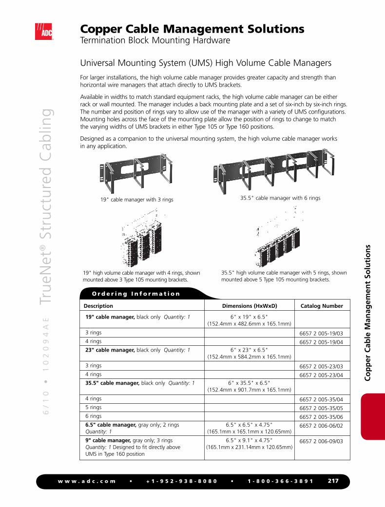
For larger installations, the high volume cable manager provides greater capacity and strength than horizontal wire managers that attach directly to UMS brackets.
Available in widths to match standard equipment racks, the high volume cable manager can be either rack or wall mounted. The manager includes a back mounting plate and a set of six-inch by six-inch rings. The number and position of rings vary to allow use of the manager with a variety of UMS configurations. Mounting holes across the face of the mounting plate allow the position of rings to change to match the varying widths of UMS brackets in either Type 105 or Type 160 positions.
Designed as a companion to the universal mounting system, the high volume cable manager works in any application.
Universal Mounting System (UMS) High Volume Cable Managers
19" cable manager with 3 rings 35.5" cable manager with 6 rings
35.5" high volume cable manager with 5 rings, shown mounted above 5 Type 105 mounting brackets.
19" high volume cable manager with 4 rings, shown mounted above 3 Type 105 mounting brackets.
Type 85 back mount frames accept 8-pair Series 2 blocks. The frames come with cable entry holes on the back and protective rubber grommets. Grommet holes are 1.5" (38.1mm) in diameter. Back mount frames are made of stainless steel.
Type 85 Back Mount Frames
Type 85 back mount frame Note: The depth dimensions listed are the actual depths of mounting brackets with no blocks installed.
O r d e r i n g I n f o r m a t i o n
Description Dimensions (HxWxD) Catalog Number
Type 85 back mount frames Quantity: 1
6 block positions, 1 hole
11 block positions, 1 hole
21 block positions, 2 holes
5.25" x 3.31" x 2.75" (133.3mm x 84.1mm x 69.9mm)
9.63" x 3.31" x 2.75" (244.5mm x 84.1mm x 69.9mm)
18.38" x 3.31" x 2.75" (466.7mm x 84.1mm x 69.9mm)
6654 2 350-06/1
6654 2 350-11/1
6654 2 350-21/2
6/
10
•
1
02
09
4A
E
Tr
ueN
et® S
tru
ctu
red
Cab
ling
219w w w . a d c . c o m • + 1 - 9 5 2 - 9 3 8 - 8 0 8 0 • 1 - 8 0 0 - 3 6 6 - 3 8 9 1
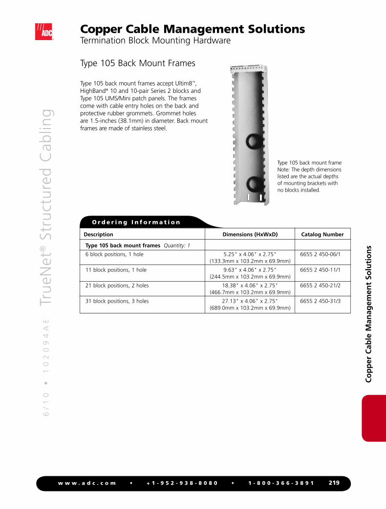
Type 105 back mount frames accept Ultim8™, HighBand® 10 and 10-pair Series 2 blocks and Type 105 UMS/Mini patch panels. The frames come with cable entry holes on the back and protective rubber grommets. Grommet holes are 1.5-inches (38.1mm) in diameter. Back mount frames are made of stainless steel.
Type 105 Back Mount Frames
Type 105 back mount frame Note: The depth dimensions listed are the actual depths of mounting brackets with no blocks installed.
O r d e r i n g I n f o r m a t i o n
Description Dimensions (HxWxD) Catalog Number
Type 105 back mount frames Quantity: 1
6 block positions, 1 hole
11 block positions, 1 hole
21 block positions, 2 holes
31 block positions, 3 holes
5.25" x 4.06" x 2.75" (133.3mm x 103.2mm x 69.9mm)
9.63" x 4.06" x 2.75" (244.5mm x 103.2mm x 69.9mm)
18.38" x 4.06" x 2.75" (466.7mm x 103.2mm x 69.9mm)
27.13" x 4.06" x 2.75" (689.0mm x 103.2mm x 69.9mm)
6655 2 450-06/1
6655 2 450-11/1
6655 2 450-21/2
6655 2 450-31/3
6/
10
•
1
02
09
4A
E
Tr
ueN
et® S
tru
ctu
red
Cab
ling
220w w w . a d c . c o m • + 1 - 9 5 2 - 9 3 8 - 8 0 8 0 • 1 - 8 0 0 - 3 6 6 - 3 8 9 1
Type 105 rod mount brackets accept Ultim8™, HighBand® 10 and 10-pair Series 2 rod mount blocks and 105mm UMS/Mini Patch Panels.Install rod mount brackets using support bars, or directly to a plywood backboard.
Type 105 Rod Mount Brackets
Rod mount bracket spacers are optional pieces that snap over the 0.47-inch (12mm) rods to maintain uniform distances between rod mount blocks.
Rod Mount Bracket Spacer
Type 105 rod mount bracket
O r d e r i n g I n f o r m a t i o n
Description Dimensions (HxWxD) Catalog Number
Type 105 rod mount brackets Quantity: 1
6 block positions
11 block positions
21 block positions
5.5" x 4.19" x 2" (139.7mm x 106.4mm x 50.8mm)
9.88" x 4.19" x 2" (250.8mm x 106.4mm x 50.8mm)
18.63" x 4.19" x 2" (473.1mm x 106.4mm x 50.8mm)
6652 2 040-06
6652 2 040-11
6652 2 040-21
O r d e r i n g I n f o r m a t i o n
Description Catalog Number
Rod mount bracket spacer Quantity: 1
0.1" (2.5mm)
0.2" (5.0mm)
6619 2 046-00
6619 2 046-01
Tech TipRod mount brackets can be easily changed from the Type 85 position to the Type 105 position (or vice versa) by removing the four screws, moving the rods in or out, and reinstalling the screws.
6/
10
•
1
02
09
4A
E
Tr
ueN
et® S
tru
ctu
red
Cab
ling
223w w w . a d c . c o m • + 1 - 9 5 2 - 9 3 8 - 8 0 8 0 • 1 - 8 0 0 - 3 6 6 - 3 8 9 1
19" mounting frame, 3-position Quantity: 1Supports up to (3) 21-position Type 85 or Type 105 mounting brackets; can be wall or rack mounted (EIA standard 19" equipment rack; 3 mounting frames fit vertically in 7' rack) with 4 mounting screws (included). Fixed jumper routing rings included
23" mounting frame, 3-position Quantity: 1Supports up to (3) 21-position Type 85 or Type 105 mounting brackets; can be wall or rack mounted (23" equipment rack) with 4 mounting screws (included). Fixed jumper routing rings included
23" mounting frame, 4-position Quantity: 1Supports up to (4) 21-position Type 85 or Type 105 mounting brackets; can be wall or rack mounted (23" equipment rack) with 4 mounting screws (included). Fixed jumper routing rings included
35.5" mounting frame, 5-position Quantity: 1Supports up to (5) 21-position Type 85 or Type 105 mounting brackets; can be wall or rack mounted (23" equipment rack) with 4 mounting screws (included). Fixed jumper routing rings included
25" x 19.38" x 4.25"(635mm x 492.1mm x 108mm)
25" x 24" x 4.25"(635mm x 609.6mm x 108mm)
25" x 24" x 4.25"(635mm x 609.6mm x 108mm)
26.5" x 35.5" x 4.25"(673.1mm x 901.7mm x 108mm)
6652 2 100-00
6652 2 114-00
6652 2 113-00
6652 2 101-00
6/
10
•
1
02
09
4A
E
Tr
ueN
et® S
tru
ctu
red
Cab
ling
224w w w . a d c . c o m • + 1 - 9 5 2 - 9 3 8 - 8 0 8 0 • 1 - 8 0 0 - 3 6 6 - 3 8 9 1
Co
pp
er C
able
Man
agem
ent
Solu
tio
ns
Copper Cable Management SolutionsSupport Bars
Wall or Rack Mount Support Bars
19" wide support bar with 4" leg 23" wide support bar, 3-position 35.5" wide support bar
O r d e r i n g I n f o r m a t i o n
Description Dimensions (HxWxD) Catalog Number
19" wide support bar, 3-position Quantity: 1 2 required for installation
(2) 19" wide support bars hold up to (3) Type 85 or Type 105 back mount frames; can be wall or rack mounted (standard 19" equipment rack)
2" leg (rack mount)
4" leg (wall mount)
23" wide wall mount support bar, 3-position Quantity: 1 2 required for installation
(2) 23" wide support bars hold up to (3) Type 85 or Type 105 back mount frames
4" leg (wall mount)
23" wide support bar, 4-position Quantity: 1 2 required for installation
(2) 23" wide support bars hold up to (4) Type 85 or 105 back mount frames; can be wall or rack mounted (standard 23" equipment rack)
2" leg (rack mount)
4" leg (wall mount)
35.5" wide support bar, Quantity: 1 2 required for installation
(2) 35.5" wide support bars hold up to (6) Type 85 or (5) Type 105 back mount frames; can be wall or rack mounted (standard 35.5" equipment rack)
2" leg (rack mount)
4" leg (wall mount)
1" x 20" x 2" (25.4mm x 508mm x 50.8mm)
1" x 20" x 4" (25.4mm x 508mm x 101.6mm)
1" x 24" x 4" (25.4mm x 609.6mm x 101.6mm)
1" x 24" x 2" (25.4mm x 609.6mm x 50.8mm)
1" x 24" x 4" (25.4mm x 609.6mm x 101.6mm)
1" x 35.69" x 2" (25.4mm x 906.5mm x 50.8mm)
1" x 36" x 4" (25.4mm x 914.4mm x 101.6mm)
6652 2 021-00
6652 2 023-02
6652 2 004-56
6652 2 012-45
6652 2 012-42
6652 2 013-00
6652 2 014-00
6/
10
•
1
02
09
4A
E
Tr
ueN
et® S
tru
ctu
red
Cab
ling
225w w w . a d c . c o m • + 1 - 9 5 2 - 9 3 8 - 8 0 8 0 • 1 - 8 0 0 - 3 6 6 - 3 8 9 1
Co
pp
er C
able
Man
agem
ent
Solu
tio
ns
Copper Cable Management SolutionsInverted Support Bars
Type 85 and Type 105 Inverted Support Bars
O r d e r i n g I n f o r m a t i o n
Description Dimensions (HxWxD) Catalog Number
19" wide support bar, 4" legs Quantity: 1 2 required for installation
3-positionSupports up to (3) Type 85 or Type 105 mounting brackets
4-positionSupports up to (4) Type 85 mounting brackets
23" wide inverted support bar, 4" legs Quantity: 1 2 required for installationSupports up to (3) Type 85 or Type 105 mounting brackets
1" x 20" x 4" (25.4mm x 508mm x 50.8mm)
1" x 20" x 4" (25.4mm x 508mm x 101.6mm)
1" x 24" x 4" (25.4mm x 609.6mm x 101.6mm)
6652 2 004-54
6652 2 004-30
6652 2 004-57
Inverted support bars are designed for equipment cabinets in which terminations must be flush with the front of the equipment rack.
19" wide inverted support bar, 3-position
19" wide inverted support bar, 4-position
23" wide inverted support bar, 3-position
6/
10
•
1
02
09
4A
E
Tr
ueN
et® S
tru
ctu
red
Cab
ling
226w w w . a d c . c o m • + 1 - 9 5 2 - 9 3 8 - 8 0 8 0 • 1 - 8 0 0 - 3 6 6 - 3 8 9 1
Co
pp
er C
able
Man
agem
ent
Solu
tio
ns
Copper Cable Management SolutionsJumper Ring Bars
O r d e r i n g I n f o r m a t i o n
Description Dimensions (HxWxD) Catalog Number
19" wide jumper ring bar Quantity: 1 4 adjustable jumper rings
No legs (wall mount)
2" legs (rack mount)
23" wide jumper ring bar Quantity: 1 4 adjustable jumper rings
No legs (wall mount)
2" legs (rack mount)
35.5" wide jumper ring bar Quantity: 1 7 adjustable jumper rings
No legs (wall mount)
2" legs (rack mount)
4.44" x 20" x 5.18" (112.8mm x 508mm x 131.6mm)
4.44" x 20" x 7.18" (112.8mm x 508mm x 182.4mm)
4.44" x 24" x 5.18" (112.8mm x 609.6mm x 131.6mm)
4.44" x 24" x 7.18" (112.8mm x 508mm x 182.4mm)
4.44" x 36" x 5.18" (112.8mm x 914.4mm x 131.6mm)
4.44" x 36" x 7.18" (112.8mm x 914.4mm x 182.4mm)
6652 2 004-00
6652 2 004-01
6652 2 006-09
6652 2 006-08
6652 2 006-00
6652 2 015-00
Jumper ring bars are used with support bars to route cross-connect jumper wires and patch cords.
19" wide jumper ring bar, no legs (wall mount)
19" wide jumper ring bar 2" legs (rack mount)
23" wide jumper ring bar no legs (wall mount)
23" wide jumper ring bar 2" legs (rack mount)
35.5" wide jumper ring bar no legs (wall mount)
35.5" wide jumper ring bar 2" legs (rack mount)
6/
10
•
1
02
09
4A
E
Tr
ueN
et® S
tru
ctu
red
Cab
ling
227w w w . a d c . c o m • + 1 - 9 5 2 - 9 3 8 - 8 0 8 0 • 1 - 8 0 0 - 3 6 6 - 3 8 9 1
Co
pp
er C
able
Man
agem
ent
Solu
tio
ns
Copper Cable Management SolutionsAccessories
Vertical cable organizer
Horizontal cable organizer
Rear wire management guide
High-density cable manager
High-density cable manager for patch panels
Ring wire manager
Ordering information follows on the next page
6/
10
•
1
02
09
4A
E
Tr
ueN
et® S
tru
ctu
red
Cab
ling
228w w w . a d c . c o m • + 1 - 9 5 2 - 9 3 8 - 8 0 8 0 • 1 - 8 0 0 - 3 6 6 - 3 8 9 1
Co
pp
er C
able
Man
agem
ent
Solu
tio
ns
Copper Cable Management SolutionsAccessories
O r d e r i n g I n f o r m a t i o n
Description Dimensions (HxWxD) Catalog Number
Vertical cable organizer Quantity: 1 Fits standard EIA 19" equipment rack; keeps patch cords and smaller wire groups organized within each bay
Horizontal cable organizer Quantity: 1 Fits standard EIA 19" equipment rack; keeps larger wire groups organized between bays
Rear wire management guide Quantity: 1 Attaches to back of standard EIA 19" equipment rack; allows organization of hidden wires and cables. Recommended for use with Plug ‘n’ Play patch panels only. One required for every 24-port group
High-density cable manager Quantity: 1 Attaches to standard EIA 19" equipment rack; includes (2) 12-24 screws for mounting to rack. Manages terminated cables on rear of high-density patch panels. 0.5" flange provides flat tie point. Smooth surface prevents snagging and protects against damage
High-density cable manager for patch panels Quantity: 1 Manages terminated cables on rear of PCB patch panel. Attaches to Category 6 and Category 5e silk-screened and fascia patch panels
Ring wire manager Quantity: 1 Utilizes 5 wire management rings
Hinged wall mount bracket Quantity: 1 Allows easy access to cable side of patch panel for circuit tracing or wiring re-termination. For left or right swing opening; simple push-pull latch keeps the panel secure in closed position
3.5" hinged wall mount bracketAccepts (2) 1RU or (1) 2RU patch panel
7" hinged wall mount bracketAccepts any 4RU combination of patch panels