(../../../../../homepage.html) A Copper Alliance (http://copperalliance.org) Member Materials Selection For High-Reliability Copper Alloy Seawater Systems by B.Todd; CDA Inc Seminar Technical Report 7044-1919. The Application of Copper Nickel Alloys in Marine Systems. Introduction Corrosion Considerations Effect of Velocity Effect of Temperature Materials Selection in Seawater Systems Piping Low Initial Cost Systems High Reliability Systems - General Copper Alloy Systems Valves General Valve Bodies – Nonferrous Systems Valve Seats and Stems – Nonferrous Systems Effect of Valve Design on Materials Selection Galvanic Considerations in Valves Seawater Pumps Pump Casings Pump Impellers Waterboxes Strainers Interactions within the System
Transcript
(../../../../../homepage.html) A Copper Alliance (http://copperalliance.org) Member
Materials Selection For High-Reliability Copper AlloySeawater Systemsby B.Todd; CDA Inc Seminar Technical Report 7044-1919. The Application of Copper Nickel Alloys inMarine Systems.
Copper-tin, copper-aluminium and copper-zinc alloys
Alloys of nickel and copper
References
INTRODUCTION
Seawater systems are used by many industries such as shipping, offshore oil and gasproduction, power plants and coastal industrial plants. The main use of seawater is for coolingpurposes but it is also used for fire-fighting, oil field water injection and for desalinationplants.
The corrosion problems in these systems have been well studied over many years, but despitepublished information on materials behavior in seawater, failures still occur.
Economic factors have to be considered in selecting materials for these systems and in thiscontext, essentially two types of system can be considered, as follows:
1. A low initial cost system largely based on carbon steel and cast iron which will requireconsiderable maintenance over the life of the plant. Such a system is a reasonablechoice in areas where labor costs are low and material is readily available.
2. A system based mainly on alloy materials which, if correctly designed and fabricated, willrequire minimum maintenance and will function reliably. Rising labor costs in mostindustries, together with the need for high reliability in capital intensive plant hasproduced a trend to this type of system.
In practice many systems are a mixture of these two logical approaches resulting in the highinitial costs of one and the high maintenance costs of the other. For example, a plant whichhas experienced costly replacement to galvanized steel piping may replace it with copper alloypiping leaving valves fittings, etc., in carbon steel and cast iron. The resulting galvaniccorrosion effects result in reduced life for these parts. Thus, higher initial costs have resultedin reduced reliability and high maintenance costs.
It is essential therefore in selecting materials for seawater systems to treat the system as a whole.This should include the heat exchangers where these are part of the system. However, thispaper is confined to the seawater systems.
Another source of problems is the different requirements of plant builders and plantoperators. The former, often bidding under competitive economic pressures, has to meet thenormal one-year guarantee at minimum cost. Seawater, although corrosive, does not normallycause rapid catastrophic failures. For example, carbon steel immersed in seawater corrodes at
(1)
about 0.1 mm/yr; whereas in, say, dilute acid, it corrodes at 100 times that rate. It is possible,therefore, to build a seawater system largely from carbon steel and cast iron to meet theguarantee requirement.
The plant operator, however, may require a 20-year trouble-free life but is often unwilling tospecify the required material and accept the higher initial costs. It is not unusual to find aprocess plan successfully handling corrosive acids but shut-down because of problems in itsseawater system which has not been given the same care in materials selection as the processequipment.
Materials selection for the two basic systems specified above are given in the followingsections. It should be noted, however, that various studies of materials in seawater systemshave concluded, that systems based on alloy materials are more economic on a life cyclecost basis.
Back to Top
CORROSION CONSIDERATIONS
The corrosion behavior of materials commonly used in seawater systems has been reviewedby the author in . Data from this review will be used in this paper and only two factorsinfluencing corrosion behavior, namely velocity and temperature, will be considered here.
Effect of Velocity
Velocity is the most important single factor influencing design and corrosion in seawatersystems. Velocity of seawater through the system influences pressure losses and thuspumping costs.
The design velocity chosen controls the dimensions of many components, for example, pipingand valves. As the costs of these components increase rapidly with pipe diameter, thenpumping costs and component costs have to be optimized. However, velocity also influencesthe corrosion behavior of the materials, and the design value chosen is often controlled bycorrosion considerations.
Corrosion of carbon steel in seawater is controlled by the availability of oxygen to the metalsurface. Thus, under static conditions, carbon steel corrodes at between 0.1 and 0.2 mm/yr,reflecting the oxygen level and temperature variations in different locations. Pitting alsooccurs.
As velocity causes a mass flow of oxygen to the surface, corrosion is very dependent on flowrate and can increase by a factor of 100 in moving from static (zero velocity) to high velocity(40 m/s) conditions.
Galvanizing confers only limited benefit under flow conditions, as corrosion of zinc alsoincreases with velocity. For the thicknesses normally used in seawater piping, it will extend thelife of the pipe for about six months.
The copper base alloys are velocity limited as impingement attack occurs when thehydrodynamic effect caused by seawater flow across the surface of such alloys exceeds thevalue at which protective films are removed and erosion-corrosion occurs. Thus, these alloys,
(2-5)
(6)
(6)
if they are to exhibit high corrosion resistance must be used at design velocities below thislimiting value.
Stainless steels are not subject to impingement attack, but are prone to pitting and crevicecorrosion under low velocity conditions and this must be taken into consideration when thesealloys are used in seawater.
Nickel base alloys such as Inconel Alloy 625, Hastelloys C-276 and C-22 and titanium arenot subject to pitting or crevice corrosion in low velocity seawater, nor do they sufferimpingement attack at high velocity. However, price limits their use to special applications inseawater systems.
Table 1 provides data on some of the materials commonly used in seawater systems. Detailsof of copper alloy compositions are given in the Appendix.
Alloy
Quiet seawater0-0.6m/s
8.2 m/scorrosionrate mm/year
35-42 m/scorrosion ratemm/year
Averagecorrosion ratein mm/year
Maximumpittingmm
Carbon steel 0.075* 2.0 - 4.5
Grey cast iron 0.55(graphitised)
4.9 4.4 13.2
Admiralty Gunmetal 0.027 0.25 0.9 1.07
85/5/5/5 Cu Sn Pb Zn 0.017 0.32 1.8 1.32
Ni Resist Cast Iron Type 1B 0.02 Nil 0.2 0.97
Ni Al Bronze(BS 1400 AB2-C)
0.055 1.12 0.22 0.97
70/30 Cu Ni + Iron <0.02* 0.25 0.12 1.47
Type 316 Stainless Steel 0.02* 1.8 <0.02 <0.01
6% Mo Stainess Steel(typical)
0.01 nil <0.02 <0.01
Ni-Cu Alloy 400 0.02* 1.3 <0.01 0.01
* 3 year test at Harbor Island, North Carolina
42 month test at Freeport, Texas
Six year test at Kure Beach, North Carolina
442 day test at Kure Beach, North Carolina. Alloy 10.6% aluminium, 2.5% iron, 5% nickel,0.75% manganese
1 year crevice corrosion data on Avesta 254 SMO, Swedish West Coast
Please Note: All of the above data (except velocity data for 6% Mo stainless) are taken fromactual test results and are thus not exactly reproducible. This is particularly true of the maximumdepth of pitting which may vary widely from test to test.
Because of the importance of velocity, it is usual in many systems to base design of pipediameters on this factor and allowable design velocities are assigned to commonly used pipematerials.
TM TM
+
+
++
+++
++++
+
++
+++
++++
(7)
In considering velocity, it is important to note that local velocities may vary considerably fromdesign velocity. This is particularly important where features of the system such as smallradius bends, orifices, partly throttled valves, misaligned flanges, etc., which can generateturbulence, give rise to local high velocities which may accelerate corrosion. It follows thatdesign and fabrication of the system should aim at minimizing turbulence raisers.
Back to Top
Effect of Temperature
Few data are available on the effect of temperature within the range normally encountered inseawater systems. It has been noted at LaQue Center of Corrosion Technology that corrosionof carbon steel increases by approximately 50% between the winter (average temperature7°C) and summer (27-29°C). Although oxygen solubility tends to fall with rise in temperature,the higher temperature tends to increase reaction rate. Evidence from work on steel inpotable waters suggests that the temperature effect is more important and corrosion, forsteel, will increase with temperature.
For copper alloys, increase in temperature accelerates film formation; this takes about 1 dayat 15°C, whereas, it may take a week or more at 2°C. It is important to continue initialcirculation of clean seawater long enough for initial film formation for all copper alloys. Moretime is needed for winter than for summer start-ups.
For stainless steels and other alloys prone to pitting and crevice corrosion, increase oftemperature tends to facilitate initiation of these types of attack. However, data onpropagation rate suggest that this declines with rise in temperature. The net effect of theseconflicting tendencies is not always predictable. Temperature also influences biological activitywhich may, in turn, influence corrosion.
Back to Top
MATERIALS SELECTION IN SEAWATER SYSTEMS
Piping
For low initial cost systems, materials such as mild steel, cast iron and steel with cement ororganic coatings are used for piping. Data on steels show that the corrosion rate in flowingseawater increases from about 0.1 mm/yr under static conditions to almost 1 mm/yr at 3 m/s.As velocities in local areas of turbulence can easily exceed 3 m/s, even when the designvelocity is much lower, corrosion tends to be accelerated in such areas. Also, as pipe thicknesstends to increase with diameter, experience in systems with steel pipes show that failurescommence first in the smaller diameters and, as the service life increases, failures occur onlarger diameters so that repair costs accelerate with time. Cast iron behaves in a similar wayto carbon steel. Small diameter steel or cast iron pipes are also easily clogged by corrosionproducts if not in continuous service.
Cement lined pipes are sometimes used. The main considerations here are:
1. Need for care in handling and fitting. If pieces of the lining break off, the area of bare
(8)
(9)
steel exposed is anodic to the steel embedded in the cement. Potential differences up to400 mv have been measured between embedded and exposed steel. The corrosionrate in such a cell will be determined by the flow of oxygen through the cement and, asthe area relationship of embedded to exposed steel is high, the corrosion rate can behigh.
2. Joints at valves and fittings. Similar considerations apply as in item 1,above). All jointsmust be covered with a cement lining if corrosion is to be avoided.
3. Spalling off of linings. If corrosion occurs, then the corrosion product produced will tendto cause the lining to spall off and pieces of lining can partially block heat exchangertubing causing local impingement attack. Physical damage can also cause the lining tospall with similar results.
Cement linings are most effective in long, straight runs of large (over 1 m) diameter. The abilityto maintain lining integrity decreases rapidly with diameter, number of fittings and valves.
Other types of linings have been considered and sometimes used for seawater piping. A studyby BSRA on a wide range of pipe linings showed that only two, namely chlorprene and softnatural rubber withstood laboratory tests simulating shipboard conditions. In terms of pipingcosts they offered economic advantage over non-ferrous piping only in sizes above about 150mm diameter. This study did not compare installed costs and Lim found that installed costof lined pipe on an offshore platform showed only a marginal cost advantage over 90-10 Cu-Nipiping. The advantage in materials cost being offset by the extra care needed for installation.
High Reliability Systems - General
In marine engineering upgrading from steel has traditionally meant a change to copper-basealloys.
High reliability systems based on copper-base alloys will now be considered.
Copper-Alloy Systems
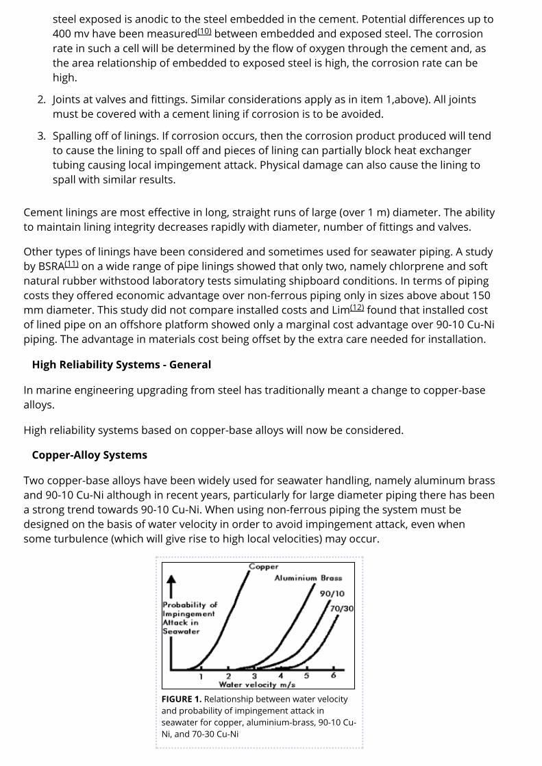
Two copper-base alloys have been widely used for seawater handling, namely aluminum brassand 90-10 Cu-Ni although in recent years, particularly for large diameter piping there has beena strong trend towards 90-10 Cu-Ni. When using non-ferrous piping the system must bedesigned on the basis of water velocity in order to avoid impingement attack, even whensome turbulence (which will give rise to high local velocities) may occur.
FIGURE 1. Relationship between water velocityand probability of impingement attack inseawater for copper, aluminium-brass, 90-10 Cu-Ni, and 70-30 Cu-Ni
(10)
(11)
(12)
(13)
Figure 1, indicates how the probability of failure of impingement attack increases withdesign velocity. For a system with high reliability acceptable design velocities are as follows:
Copper 0.75 m/s
Aluminum brass 2.5 m/s
90-10 Cu-Ni 3.0 m/s
70-30 Cu-Ni 3.5 m/s
The use of 70-30 Cu-Ni is confined to submarines where its high strength is advantageous.Due to the low design velocity and hence large pipe sizes, copper is uneconomical except forsmall diameter piping for essentially domestic applications, so that the real choice is between90-10 Cu-Ni and aluminum brass. Both materials are technically suitable, provided the systemis designed to the water velocities given above and both have been successfully used in manyseawater systems. However, the current trend is towards the use of 90-10 Cu-Ni, the reasonsfor this being:
1. Its better weldability. Although aluminum brass can be welded using aluminum bronzefiller materials, this is a relatively difficult procedure. Silver brazing is also used but this isexpensive; firstly, because a high silver content (50% min) alloy is needed to provide therequired corrosion resistance; and secondly, because the technique is difficult and timeconsuming for diameters above about 50 mm.
2. Its high stress corrosion resistance. 90-10 Cu-Ni does not normally require any stressrelief heat treatment after fabrication. Aluminum brass requires stress relief to avoid thepossibility of stress corrosion cracking to which it is susceptible in seawater.
3. Its good experience. Gilbert reports only nine cases of premature failure over aperiod of 20 years. This is a remarkable result considering the large tonnage of the alloyin use throughout the world. Only three of the failures involved excessive turbulence,suggesting current design velocities may be conservative.
It is also relevant to note that most of the world's navies have standardized on 90-10 Cu-Ni forpiping in surface vessels, thus ensuring worldwide availability of facilities for fabrication of thealloy.
Some use has been made of aluminum bronzes for piping in components such as pumpcolumns. Nickel aluminum bronze is preferred for seawater, and usually in case form (BS 1400AB2 or UNS C95800). Care is needed with components fabricated from plate as the heataffected zones are sensitive to selective phase corrosion (dealuminification) which can lead tocracking. Risk of this can be reduced (but not eliminated) by heat treatment (at 650-675°C forsix hours) after welding.
The design water velocities given above have been proved in service over many years and, asexperience has been good, there has been a tendency to raise them to achieve economies inpipe costs. British Standard BSMA 18 allows up to 3.0 m/s for aluminum brass and 3.5 m/s for90-10 Cu-Ni pipe for bores above 100 mm. Below this size the velocity is reducedprogressively. Although it is logical from a consideration of water flow through pipes, to expecta reduction in risk of impingement attack with increase in diameter and hence to allow higherwater speeds in larger diameter pipes, there are few data on which to base design. Oneapproach to this problem is to use the results obtained by Efird which relate the onset ofimpingement attack to a critical shear stress (resulting from the flow velocity) and pipe
(13)
(14)
(15)
2 2
diameter. If the value of critical shear stress of 43.1 N/m (0.9 lb/ft ) for 90-10 Cu-Ni isaccepted, then it is possible to relate critical shear stress to pipe diameter at a given seawatertemperature.
Table 2 provides some data for seawater at 5°C (Higher temperatures would give highercritical velocities.)
TABLE 2.Effect of pipe diameter on criticalvelocity in seawater at 5°C for 90-10 Cu-Ni
Minimum pipe diametermm*
Calculated critical velocityfor impingementm/s
72.15 4.70
103.00 4.85
154.25 5.08
212.30 5.25
315.00 5.42
447.20 5.52
* From Table 2 in British Standard BSMA 18
The values in Table 2 are based on parallel flow tests over plane specimens and, as would beexpected, are higher than design water velocities which must allow for local turbulenceeffects. Thus, these absolute values should not be used as design values but could provide aguide to the designer to vary design water velocity with diameter to economise in systemcosts.
Back to Top
Valves
Many corrosion problems in seawater systems occur in valves. Often such problems are dueto the use of steel or cast iron valves with non-ferrous piping. Although the life of such valvesin a steel or cast iron pipe system is short (i.e., two to three years) when fitted in a alloysystem, it may be less than a year due to the galvanic effects from the piping.
The three main components of a valve are the body, valve seats and the shafts or stems; thesewill be considered separately. It should be noted, however, in a system with a nominalseawater velocity of a few meters-per-second flow through the valve, that the valve,depending on its design, may give rise to turbulence and much higher local velocities,particularly when the valves are used for throttling.
Back to Top
Valve Bodies – Non-Ferrous Systems
2 2
The basic low cost valve used in ferrous pipe systems has a cast iron body with 60-40 brassinternals. Depending on design, corrosion rates of several millimeters per year can occur onthe body. The body cathodically protects the internals (until a layer of graphitic corrosionproduct forms) and the valve will function for two to three years.
Coatings on valve bodies are often used but their success depends mainly on the valve design(see later). In all cases, the life of the coating depends on its integrity, as manufactured, afterinstallation and in service. Any break in a coating can result in intense corrosion andperforation or the valve body.
Upgrading of valve body materials to give higher reliability requires the use of alloys with goodcorrosion resistance. Such materials are copper base alloys such as nickel aluminum bronzes,Admiralty and leaded gunmetals and cast Cu-Nis. All these alloys are characterized by goodresistance to static seawater (necessary for shut-down conditions) and to flowing seawater.Table 3 gives some data under static and flowing conditions.
TABLE 3. Effect of velocity of some cast copper base alloys
Alloy
Quiet seawater0.06 m/sec
Moderatevelocity8.25m/sec
High velocity tests35-42 m/sec
Generalcorrosionmm/year
Maximumpittingmm
Corrosionmm/year
Corrosionratemm/year30 daytest
Remarksonlowvelocitydata
88/10/2 Cu Sn Zn Admiralty Gunmetal 0.025 0.025 0.4 - 1.0 0.75 - 1.142 monthsat Freeport,TX
70-30 Cu Ni + 1.6% Cr 0.0010 0.28 0.22* 0.5 181 days atFLLCL
* At 15.3 meters/second
In relation to Table 3, it is interesting to note that in some cases, the corrosion at about 35-42m/s is similar to that at 8.25 m/s. This indicates that impingement attack is occurring at thelower velocity and, under these circumstances, increase in velocity produces little increase incorrosion. The aim should be to use the alloy at a velocity lower than that causingimpingement. Unfortunately, this cannot always be calculated so that where impingement is apossibility, alloys with high resistance such as nickel aluminum bronze or cast Cu-Ni (pluschromium) should be used.
Nickel-Resist iron valves are often used in ferrous systems to improve the valve reliability.They are also used in non-ferrous systems but copper-alloy valves are more common in suchsystems. Nickel aluminum bronze has high strength and this makes it attractive, particularlyfor large valves. Also, it has high resistance to impingement attack and this may be ofimportance in globe valves used under throttling conditions.
Back to Top
Valve Seats and Stems - Non-Ferrous Systems
Valve seats, particularly those in throttling service, experience high water velocities, and datafrom (6) show that materials with high resistance to fast flowing seawater are stainless steels,nickel-base alloys and Monel alloy 400. Experience shows that when manufacturers upgradethe body material they often use the same materials for seats and stem as in a cast iron valve,i.e., 60-40 brass. Under these conditions the life of the valve internals is extremely shortbecause, having lost the cathodic protection of the ferrous body, they fail by dezincification ina few months. Figure 2 shows dezincification of a 60-40 brass stem from a bronze valve. Thisis probably the most common cause of failure in non-ferrous valves. Although this type ofcorrosion is well-known, the rate of attack is often surprisingly high. The sample in Figure 2failed in less than one year – the original diameter was 25 mm.
FIGURE 2. Dezincification of a 60-40 brassstem from a bronze valve
Although stainless steel (AISI Type 316) will give good life in a non-ferrous valve, it is liable topit (particularly in crevices) when the system is not in use and on a life cycle cost basis, thenickel-copper alloys are a better choice. Another problem with stainless steels is the frequentuse of steels of lower alloy content than Type 316 and these can pit very rapidly in seawater.Such materials are 12% Cr (AISI Type 410) and 18% Cr (AISI Type 430) stainless steels. Use ofthese alloys in seawater systems often results in early failure.
In ball and butterfly valves, one of the seats may be non-metallic, e.g., an elastomer.
Inconel alloy 625 which has high resistance to both static and flowing seawater has beenused as a weld overlay to produce highly resistant surfaces in critical areas of valves andshafts and also on pump castings. This alloy has excellent weld deposition characteristics andcan be used as a general purpose overlay for avoidance of, or repair to, areas of corrosiondamage in carbon, low alloy and stainless steel components.
Back to Top
Effect of Valve Design on Materials Selection
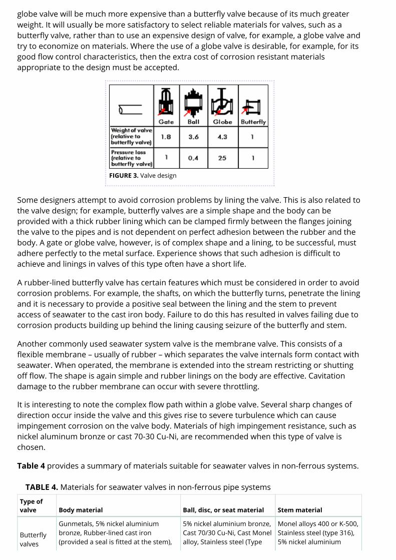
Valves are a relatively expensive part of a seawater system but the cost of a valve depends onthe design used. Figure 3 shows some commonly used valve designs and gives an indicationof their weight and pressure loss. Apart from any manufacturing difficulties, it is evident that a
TM
globe valve will be much more expensive than a butterfly valve because of its much greaterweight. It will usually be more satisfactory to select reliable materials for valves, such as abutterfly valve, rather than to use an expensive design of valve, for example, a globe valve andtry to economize on materials. Where the use of a globe valve is desirable, for example, for itsgood flow control characteristics, then the extra cost of corrosion resistant materialsappropriate to the design must be accepted.
FIGURE 3. Valve design
Some designers attempt to avoid corrosion problems by lining the valve. This is also related tothe valve design; for example, butterfly valves are a simple shape and the body can beprovided with a thick rubber lining which can be clamped firmly between the flanges joiningthe valve to the pipes and is not dependent on perfect adhesion between the rubber and thebody. A gate or globe valve, however, is of complex shape and a lining, to be successful, mustadhere perfectly to the metal surface. Experience shows that such adhesion is difficult toachieve and linings in valves of this type often have a short life.
A rubber-lined butterfly valve has certain features which must be considered in order to avoidcorrosion problems. For example, the shafts, on which the butterfly turns, penetrate the liningand it is necessary to provide a positive seal between the lining and the stem to preventaccess of seawater to the cast iron body. Failure to do this has resulted in valves failing due tocorrosion products building up behind the lining causing seizure of the butterfly and stem.
Another commonly used seawater system valve is the membrane valve. This consists of aflexible membrane – usually of rubber – which separates the valve internals form contact withseawater. When operated, the membrane is extended into the stream restricting or shuttingoff flow. The shape is again simple and rubber linings on the body are effective. Cavitationdamage to the rubber membrane can occur with severe throttling.
It is interesting to note the complex flow path within a globe valve. Several sharp changes ofdirection occur inside the valve and this gives rise to severe turbulence which can causeimpingement corrosion on the valve body. Materials of high impingement resistance, such asnickel aluminum bronze or cast 70-30 Cu-Ni, are recommended when this type of valve ischosen.
Table 4 provides a summary of materials suitable for seawater valves in non-ferrous systems.
TABLE 4. Materials for seawater valves in non-ferrous pipe systems
Type ofvalve Body material Ball, disc, or seat material Stem material
Butterflyvalves
Gunmetals, 5% nickel aluminiumbronze, Rubber-lined cast iron(provided a seal is fitted at the stem),
Monel alloys 400 or K-500,Stainless steel (type 316),5% nickel aluminium
Cast 70-30 Cu-Ni 316) bronze
Globe,gate, orball valves
As above, except that rubber linedvalves should be avoided As above As above
Membranevalves
Rubber lined cast iron Rubber (membrane) Not critical as there is noseawater content
Back to Top
Galvanic Considerations in Valves
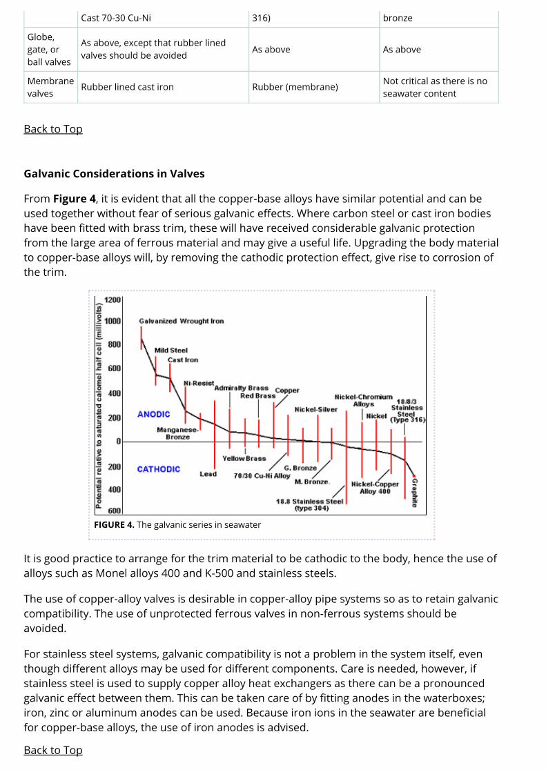
From Figure 4, it is evident that all the copper-base alloys have similar potential and can beused together without fear of serious galvanic effects. Where carbon steel or cast iron bodieshave been fitted with brass trim, these will have received considerable galvanic protectionfrom the large area of ferrous material and may give a useful life. Upgrading the body materialto copper-base alloys will, by removing the cathodic protection effect, give rise to corrosion ofthe trim.
FIGURE 4. The galvanic series in seawater
It is good practice to arrange for the trim material to be cathodic to the body, hence the use ofalloys such as Monel alloys 400 and K-500 and stainless steels.
The use of copper-alloy valves is desirable in copper-alloy pipe systems so as to retain galvaniccompatibility. The use of unprotected ferrous valves in non-ferrous systems should beavoided.
For stainless steel systems, galvanic compatibility is not a problem in the system itself, eventhough different alloys may be used for different components. Care is needed, however, ifstainless steel is used to supply copper alloy heat exchangers as there can be a pronouncedgalvanic effect between them. This can be taken care of by fitting anodes in the waterboxes;iron, zinc or aluminum anodes can be used. Because iron ions in the seawater are beneficialfor copper-base alloys, the use of iron anodes is advised.
Back to Top
Seawater Pumps
Centrifugal pumps are normally used in seawater systems and are often driven by constantspeed electric motors. At the normal speed of rotation, the tip speed of the pump impeller canreach 20 m/s and at this velocity, most copper-alloys corrode rapidly in seawater. Fortunately,however, only certain components of the pump are exposed to these high velocities, andapart from these components, copper-base alloys can usually be used successfully in copperalloy systems.
Pump Casings
In copper alloy pumps, there is normally sufficient clearance left between the impeller and thecasing so that the water flowing from the impeller does not impinge directly on the casing butis absorbed into the slower moving stream of water flowing over the metal surface towardsthe pump delivery pipe. Provided direct impingement is avoided, then materials such asgunmetals, aluminum bronze and cast 70-30 Cu-Nis perform satisfactorily. However, therehave been cases of premature pump casing failures in recent years showing that directimpingement can occur. This may be due to increase in pump speed or the tendency to upratethe output from standard pump designs. Where such failures have been experienced, the lifeof the casing has been very short, for example, about 18 months. To avoid failures of this type,either the design must be amended so as to reduce seawater velocity at the metal surface, ormaterials of higher resistance must be used. Experience shows that cast 70-30 Cu-Ni and 5%nickel aluminum bronze have higher resistance than gun metal or tin bronzes. Recentresearch, however, has shown chromium-containing 70-30 Cu-Ni to have higher resistancethan other copper-base alloys to fast flowing seawater, as shown in Table 3.
Where pump parts are fabricated by welding from nickel aluminum bronze plate, there is aserious risk of selective phase corrosion (dealuminification) in the heat effected zone of theweld. This can crack if stressed, e.g., by water hammer effects.
Back to Top
Pump Impellers
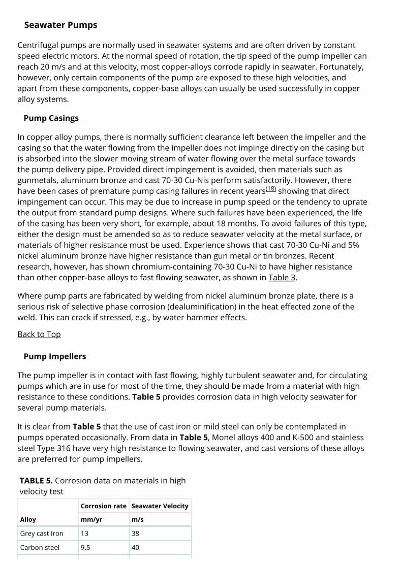
The pump impeller is in contact with fast flowing, highly turbulent seawater and, for circulatingpumps which are in use for most of the time, they should be made from a material with highresistance to these conditions. Table 5 provides corrosion data in high velocity seawater forseveral pump materials.
It is clear from Table 5 that the use of cast iron or mild steel can only be contemplated inpumps operated occasionally. From data in Table 5, Monel alloys 400 and K-500 and stainlesssteel Type 316 have very high resistance to flowing seawater, and cast versions of these alloysare preferred for pump impellers.
TABLE 5. Corrosion data on materials in highvelocity test
Alloy
Corrosion rate Seawater Velocity
mm/yr m/s
Grey cast Iron 13 38
Carbon steel 9.5 40
(18)
Monel Alloy 400 0.010 43
Monel alloy K-500 0.010 43
Stainless steel 0.005 43
These alloys do not suffer from impingement attack but may pit when the pump is stationaryand full of seawater. It should be noted, however, that the pitting likely to be experienced isoften less severe than the general impingement corrosion which may occur at the tip of acopper-base alloy impeller and hence stainless steel or cast Monel Alloy 400 are preferred forthis application.
Back to Top
Waterboxes
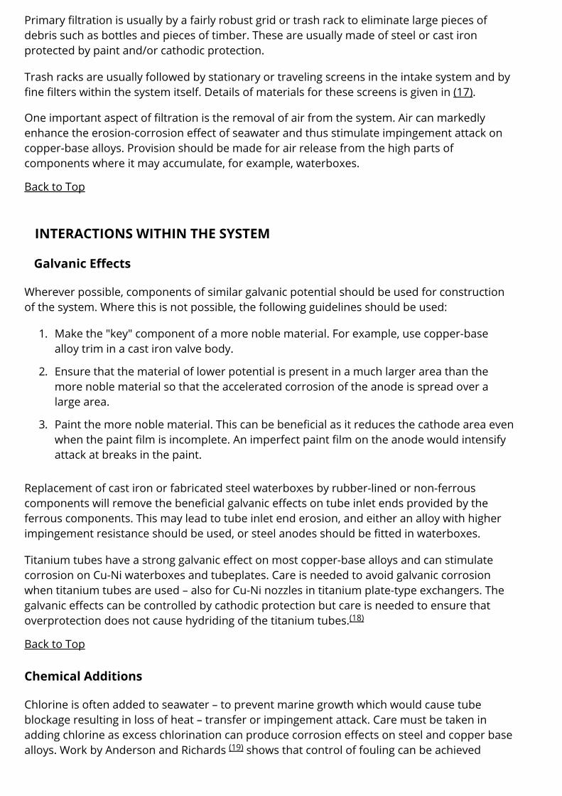
The commonest materials for waterboxes are cast iron or mild steel, and these are oftenrubber or plastic lined to extend their life. Unlined boxes, as used in older installations,corroded and helped protect the tubes and tube plates. However, the corrosion of thewaterbox itself is a serious problem and there is a trend towards non-ferrous boxes,particularly for condensers. Figure 5 shows a fabricated 90-10 Cu-Ni waterbox for a shipcondenser. The use of this type of construction is economic, as all the external stiffening iscarbon steel and only the metal in contact with seawater is Cu-Ni.
FIGURE 5. Fabricated 90-10 Cu-Niwaterbox
Waterboxes in nickel aluminum bronze are also used, particularly with titanium tubes becauseof galvanic considerations. These are usually cast – fabrications may require cathodicprotection to avoid selective corrosion on welds (see piping section).
Back to Top
Strainers
The purpose of strainers is to filter out materials detrimental to the system, for example, tominimize fouling and plugging of heat exchanger tubes.
Primary filtration is usually by a fairly robust grid or trash rack to eliminate large pieces ofdebris such as bottles and pieces of timber. These are usually made of steel or cast ironprotected by paint and/or cathodic protection.
Trash racks are usually followed by stationary or traveling screens in the intake system and byfine filters within the system itself. Details of materials for these screens is given in (17).
One important aspect of filtration is the removal of air from the system. Air can markedlyenhance the erosion-corrosion effect of seawater and thus stimulate impingement attack oncopper-base alloys. Provision should be made for air release from the high parts ofcomponents where it may accumulate, for example, waterboxes.
Back to Top
INTERACTIONS WITHIN THE SYSTEM
Galvanic Effects
Wherever possible, components of similar galvanic potential should be used for constructionof the system. Where this is not possible, the following guidelines should be used:
1. Make the "key" component of a more noble material. For example, use copper-basealloy trim in a cast iron valve body.
2. Ensure that the material of lower potential is present in a much larger area than themore noble material so that the accelerated corrosion of the anode is spread over alarge area.
3. Paint the more noble material. This can be beneficial as it reduces the cathode area evenwhen the paint film is incomplete. An imperfect paint film on the anode would intensifyattack at breaks in the paint.
Replacement of cast iron or fabricated steel waterboxes by rubber-lined or non-ferrouscomponents will remove the beneficial galvanic effects on tube inlet ends provided by theferrous components. This may lead to tube inlet end erosion, and either an alloy with higherimpingement resistance should be used, or steel anodes should be fitted in waterboxes.
Titanium tubes have a strong galvanic effect on most copper-base alloys and can stimulatecorrosion on Cu-Ni waterboxes and tubeplates. Care is needed to avoid galvanic corrosionwhen titanium tubes are used – also for Cu-Ni nozzles in titanium plate-type exchangers. Thegalvanic effects can be controlled by cathodic protection but care is needed to ensure thatoverprotection does not cause hydriding of the titanium tubes.
Back to Top
Chemical Additions
Chlorine is often added to seawater – to prevent marine growth which would cause tubeblockage resulting in loss of heat – transfer or impingement attack. Care must be taken inadding chlorine as excess chlorination can produce corrosion effects on steel and copper basealloys. Work by Anderson and Richards shows that control of fouling can be achieved
(18)
(19)
without detriment to materials if the chlorination is carefully controlled. This is best done bymeasuring the residual chlorine at the plant outlet and adjusting the chlorine dose to maintainthis at a low level, e.g. 0.1-0.2 ppm.
Another substance commonly found in seawater systems is the ferrous ion. In older systemswith ferrous components, corrosion of these components provided a continuous supply offerrous ions which, experience has shown, had an effect on corrosion of copper-base alloys,notably aluminum brass tubes. In modern systems, where the supply of ferrous ions may belargely eliminated either by use of non-ferrous materials or by use of coating, failures ofaluminum brass heat exchange tubes have been experienced. This can be rectified eitherby deliberately injecting ferrous ions into the system or by fitting Cu-Ni tubes which are lessaffected by ferrous ions in the water.
Back to Top
CONCLUSION
By treating seawater systems as a whole it is possible to build corrosion resistant, reliablesystems with low maintenance costs.
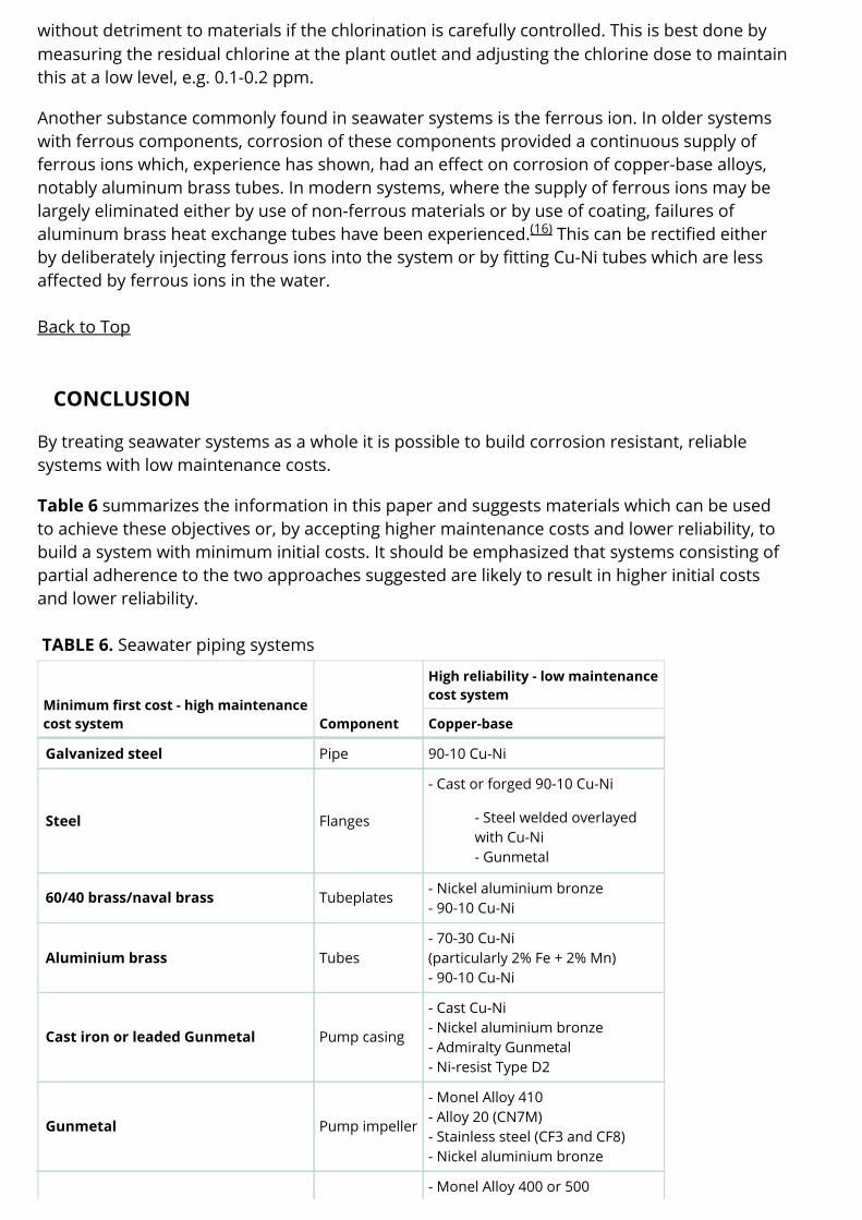
Table 6 summarizes the information in this paper and suggests materials which can be usedto achieve these objectives or, by accepting higher maintenance costs and lower reliability, tobuild a system with minimum initial costs. It should be emphasized that systems consisting ofpartial adherence to the two approaches suggested are likely to result in higher initial costsand lower reliability.
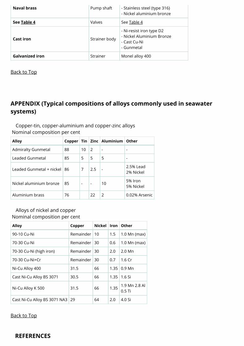
TABLE 6. Seawater piping systems
Minimum first cost - high maintenancecost system Component
Alloys of nickel and copperNominal composition per cent
Alloy Copper Nickel Iron Other
90-10 Cu-Ni Remainder 10 1.5 1.0 Mn (max)
70-30 Cu-Ni Remainder 30 0.6 1.0 Mn (max)
70-30 Cu-Ni (high iron) Remainder 30 2.0 2.0 Mn
70-30 Cu-Ni+Cr Remainder 30 0.7 1.6 Cr
Ni-Cu Alloy 400 31.5 66 1.35 0.9 Mn
Cast Ni-Cu Alloy BS 3071 30.5 66 1.35 1.6 Si
Ni-Cu Alloy K 500 31.5 66 1.35 1.9 Mn 2.8 Al0.5 Ti
Cast Ni-Cu Alloy BS 3071 NA3 29 64 2.0 4.0 Si
Back to Top
REFERENCES
1. "Marine Corrosion." F. L. LaQue, Wiley Interscience.
2. "Copper Alloys in Marine Engineering Applications." P. T. Gilbert and W. North. Trans. ofthe Institute of Marine Engineers, 1972, 84, Part 16 520.
3. "Design Study of Condensers and Circulation Systems." S. A. Fielding, MarineTechnology, April, 1971.
4. "Sea Water Systems." W. H. Falconer and L. K. Wong. Institute of Marine Engineers,Materials Section. Symposium P. 26, London, 1968.
5. of Materials Usage in Seawater Systems." D. Bailey. Project G30, May, 1982, BSRA.
6. "Selection of Materials for High Reliability Seawater Systems." Supplement to Chemistryand Industry. 2nd January, 1977.
7. BSMA 18. Salt Water Piping Systems in Ships.
8. G. Butler and A. D. Mercer, Nature 1975. Vol. 256 Issue No. 5520. P 179-720.
9. "Stainless Steels for Seawater Service," A. P. Bond, M. J Dundas, S. Eherot and M.Semchyshen. Stainless Steel '77 Paper 15.
10. "Galvanic Action of Steel in Concrete." H. Arup. Korrosionscentralen Report, August,1977.
11. "Lined Steel Piping for Salt-Water Services." Final Report NS 460 British Ship ResearchAssociation.
12. "Use of Cu-Ni Alloy Materials for Offshore Seawater Piping." L. H. Lim, Offshore Europe77 Conference, Aberdeen.
13. "Copper Alloys for Seawater Systems." P. T. Gilbert, Institute of Marine EngineersSymposium, London, March 1968.
14. "Corrosion Resisting Properties of 90/10 Cu-Ni Iron Alloy with Particular Reference toOffshore Oil and Gas Applications." P.T. Gilbert, 7th International Congress on MetallicCorrosion, Oct. 4th-11th, 1978. Rio De Janeiro, Brazil. Paper No. 126.
15. "The Effects of Fluid Dynamics on The Corrosion of Copper Base Alloys in Seawater." K.D. Efird, Corrosion '76 Conference, Houston, March, 1976.
16. "Problems in Seawater Circulating Systems." E. B. Shone, British Corrosion Journal 1974,No. 1. pp. 32-38.
17. "Lower Cost Water by Proper Materials Selection." Proceedings of 3rd EuropeanSymposium on Fresh Water from the Sea. pp. 549-578.
18. "Characterization of Titanium Condenser Tube Hydriding at Two Florida Power and LightCompany Plants." J. P. Fulford, R. W. Schutz, R. C. Lisenbey. Joint ASME/IEEE PowerGeneration Conference, Miami Beach, Florida, October 4-8, 1987.
19. "Chlorination of Seawater - Effects on Fouling and Corrosion." D. B. Anderson and R. B.Richards, Journal of Engineering for Power, July, 1966.