+ All Categories
Home > Documents > Copyright 2010 John Wiley & Sons, Inc4 - 1 Business Data Communications and Networking 10th Edition...

Copyright 2010 John Wiley & Sons, Inc4 - 1 Business Data Communications and Networking 10th Edition...

Date post: 01-Jan-2016
Category:
Upload: melanie-brown
View: 218 times
Download: 1 times
Share this document with a friend
Popular Tags:
50
Copyright 2010 John Wiley & Sons, Inc 4 - 1 Business Data Communications and Networking 10th Edition Jerry Fitzgerald and Alan Dennis John Wiley & Sons, Inc Dwayne Whitten, D.B.A Mays Business School Texas A&M University
Transcript

Copyright 2010 John Wiley & Sons, Inc 4 - 1

Business Data Communications and Networking

10th Edition

Jerry Fitzgerald and Alan Dennis

John Wiley & Sons, Inc

Dwayne Whitten, D.B.AMays Business SchoolTexas A&M University

Copyright 2010 John Wiley & Sons, Inc 4 - 2

Chapter 4

Data Link Layer

Copyright 2010 John Wiley & Sons, Inc 4 - 3

Chapter 4 Outline

• Media Access Control– Controlled Access, Contention, Relative Performance

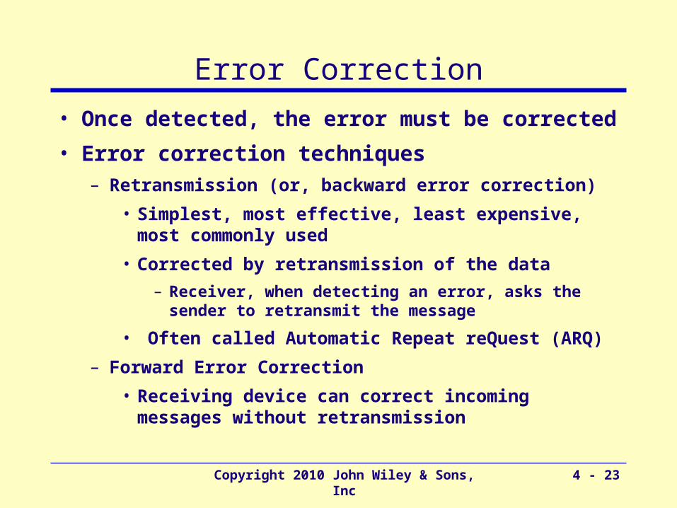
• Error Control – Sources of Errors, Error Prevention, Error Detection,

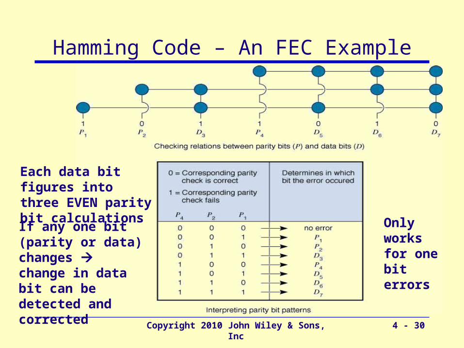
Error Correction via Retransmission, Forward Error Correction

• Data Link Protocols– Asynchronous Transmission, Synchronous

Transmission

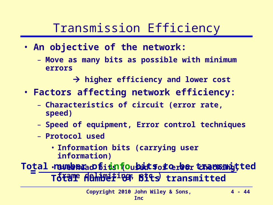
• Transmission Efficiency

Copyright 2010 John Wiley & Sons, Inc 4 - 4

Data Link Layer - Introduction

• Responsible for moving messages from one device to another

• Controls the way messages are sent on media

• Organizes physical layer bit streams into coherent messages for the network layer

• Major functions of a data link layer protocol– Media Access Control

• Controlling when computers transmit– Error Control

• Detecting and correcting transmission errors– Message Delineation

• Identifying the beginning and end of a message

Data Link Layer

Physical Layer

Network Layer

Copyright 2010 John Wiley & Sons, Inc 4 - 5

Media Access Control (MAC)

• Controlling when and what computer transmit– Important when more than one computer wants to send

data at the same time over the same, shared circuit

• Point-to-point half duplex links

– computers take turns

• Multipoint configurations

– Ensure that no two computers attempt to transmit data at the same time

• Two possible approaches– Controlled access

– Contention based access

Copyright 2010 John Wiley & Sons, Inc 4 - 6

Controlled Access

• Controlling access to shared resources– Acts like a stop light

• Commonly used by mainframes (or its front end processor)– Determines which circuits have access to

mainframe at a given time

• Also used by some LAN protocols– Token ring, FDDI

• Major controlled access methods– X-ON/X-OFF and Polling

Copyright 2010 John Wiley & Sons, Inc 4 - 7

Polling

• Process of transmitting to a client only if asked and/or permitted– Client stores the information to be transmitted

– Server (periodically) polls the client if it has data to send

– Client, if it has any, sends the data

– If no data to send, client responds negatively, and server asks the next client

• Types of polling– Roll call polling

– Hub polling (also called token passing)

Copyright 2010 John Wiley & Sons, Inc 4 - 8

Roll Call Polling

• Involves waiting: Poll and wait for a response

• Needs a timer to prevent lock-up (by client not answering)

Server

EB

CD

A

Check each client (consecutively and periodically) to see if it wants to transmit : A, B, C, D, E, A, B, …

Clients can also be prioritized so that they are polled more frequently: A, B, A, C, A, D, A, E, A, B, ..

Clients

Copyright 2010 John Wiley & Sons, Inc 4 - 9

Hub Polling (Token Passing)

E

B

C

D

A token

One computer starts the poll:

• sends message (if any) then

• passes the token to the next computer

• token is a unique series of bits

Continues in sequence until the token reaches the first computer, which starts the polling cycle all over again

Copyright 2010 John Wiley & Sons, Inc 4 - 10

Contention

• Transmit whenever the circuit is free

• Collisions

– Occur when more than one computer transmits at the same time

– Need to determine which computer is allowed to transmit first after the collision

• Used commonly in Ethernet LANs

• Can be problematic in heavy usage networks

Copyright 2010 John Wiley & Sons, Inc 4 - 11

Relative PerformanceDepends on network conditions

Work better for smaller networks with low usage

Work better for networks with high traffic volumes

When volume is high, performance deteriorates (too many collisions)

Network more efficiently used

Cross-over Cross-over point: point:

About 20 About 20 computerscomputers

Copyright 2010 John Wiley & Sons, Inc 4 - 12
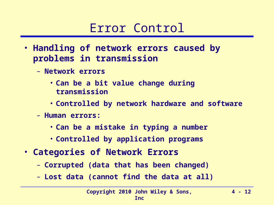
Error Control

• Handling of network errors caused by problems in transmission– Network errors

• Can be a bit value change during transmission

• Controlled by network hardware and software

– Human errors:

• Can be a mistake in typing a number

• Controlled by application programs

• Categories of Network Errors– Corrupted (data that has been changed)

– Lost data (cannot find the data at all)

Copyright 2010 John Wiley & Sons, Inc 4 - 13

Error Control (Cont.)

• Error Rate

– 11 bit error in nn bits transmitted, e.g., 1 in 500,000

• Burst error (more common)– Many bits are corrupted at the same time

– Errors not uniformly distributed

• e.g., 100 in 50,000,000 1 in 500,000

Copyright 2010 John Wiley & Sons, Inc 4 - 14

Sources of Errors

• Line noise and distortion – major cause– More likely on electrical media

– Undesirable electrical signal

– Introduced by equipment and natural disturbances

– Degrades performance of a circuit

– Manifestation

• Extra bits

• “Flipped” bits

• Missing bits

Major Functions of Error Control

• Error prevention

• Error detection

• Error correction

Copyright 2010 John Wiley & Sons, Inc 4 - 15

Copyright 2010 John Wiley & Sons, Inc 4 - 16

Source of Error What causes it How to prevent it

Line Outages 

Faulty equipment, Storms, Accidents (circuit fails)


White Noise Movement of electrons (thermal energy)

Increase signal strength (increase SNR)

Impulse Noise Sudden increases in electricity (e.g., lightning, power surges)

Shield or move the wires

Cross-talk Multiplexer guard bands are too small or wires too close together

Increase the guard bands, ormove or shield the wires

Echo 

Poor connections (causing signal to be reflected back to the source)

Fix the connections, ortune equipment

Attenuation 

Gradual decrease in signal over distance (weakening of a signal)

Use repeaters or amplifiers

Intermodulation Noise

Signals from several circuits combine

Move or shield the wires

Jitter 

Analog signals change (small changes in amp., freq., and phase)

Tune equipment

Harmonic Distortion 

Amplifier changes phase (does not correctly amplify its input signal)

Tune equipment

Sources of Errors and Prevention

mo

stly on

analo

gM

ore im

po

rtant

Copyright 2010 John Wiley & Sons, Inc 4 - 17

Error Detection

Mathematical calculations

?=

Mathematical calculations

Data to be transmitted

Sender calculates an Error Detection Value (EDV) and transmits it along with data

Receiver recalculates EDV and checks it against the received EDV

– If the same No errors in transmission

– If different Error(s) in transmission

EDV

Larger the size, better error detection (but lower efficiency)

Copyright 2010 John Wiley & Sons, Inc 4 - 18

Error Detection Techniques

• Parity checks

• Checksum

• Cyclic Redundancy Check (CRC)

Copyright 2010 John Wiley & Sons, Inc 4 - 19

Parity Checking

• One of the oldest and simplest

• A single bit added to each character– Even parity: number of 1’s remains even

– Odd parity: number of 1’s remains odd

• Receiving end recalculates parity bit– If one bit has been transmitted in error the received

parity bit will differ from the recalculated one

• Simple, but doesn’t catch all errors – If two (or an even number of) bits have been transmitted

in error at the same time, the parity check appears to be correct

– Detects about 50% of errors

Copyright 2010 John Wiley & Sons, Inc 4 - 20

Examples of Using Parity

sender receiver01101010

EVEN parity

parity

number of all transmitted 1’s remains EVEN

To be sent: Letter V in 7-bit ASCII: 0110101

sender receiver01101011

ODD parity

paritynumber of all transmitted 1’s remains ODD

Checksum

Copyright 2010 John Wiley & Sons, Inc 4 - 21

• A checksum (usually 1 byte) is added to the end of the message

• It is 95% effective

• Method:• Add decimal values of each character in the message

• Divide the sum by 255

• The remainder is the checksum value

Copyright 2010 John Wiley & Sons, Inc 4 - 22

P / G = Q + R / G

Cyclic Redundancy Check (CRC)

– Most powerful and most common– Detects 100% of errors (if number of errors <= size of R)

–Otherwise: CRC-16 (99.998%) and CRC-32 (99.9999%)

Message (treated as one long binary number)

A fixed number (determines the length of the R)

Remainder:–added to the message as EDV

–could be 8 bits, 16 bits, 24 bits, or 32 bits long

–CRC16 has R of 16 bits

Quotient (whole number)

Example:P = 58G = 8Q = 7R = 2

Copyright 2010 John Wiley & Sons, Inc 4 - 23

Error Correction

• Once detected, the error must be corrected

• Error correction techniques– Retransmission (or, backward error correction)

• Simplest, most effective, least expensive, most commonly used

• Corrected by retransmission of the data

– Receiver, when detecting an error, asks the sender to retransmit the message

• Often called Automatic Repeat reQuest (ARQ)

– Forward Error Correction

• Receiving device can correct incoming messages without retransmission

Copyright 2010 John Wiley & Sons, Inc 4 - 24

Automatic Repeat reQuest (ARQ)

• Process of requesting a data transmission be resent

• Main ARQ protocols– Stop and Wait ARQ (A half duplex technique)

• Sender sends a message and waits for acknowledgment, then sends the next message

• Receiver receives the message and sends an acknowledgement, then waits for the next message

– Continuous ARQ (A full duplex technique)

• Sender continues sending packets without waiting for the receiver to acknowledge

• Receiver continues receiving messages without acknowledging them right away

Copyright 2010 John Wiley & Sons, Inc 4 - 25

Stop and Wait ARQ

Sends Packet A, then waits to hear from receiver.

Sends

acknowledgement

Sends negative

acknowledgement

Resends the packet again

Sends the next packet (B)

Sender Receiver

Sends

acknowledgement

Copyright 2010 John Wiley & Sons, Inc 4 - 26

Continuous ARQSender sends packets continuously without

waiting for receiver to acknowledge

Notice that acknowledgments now

identify the packet being acknowledged.

Receiver sends back a NAK for a specific packet to be resent.

Copyright 2010 John Wiley & Sons, Inc 4 - 27

Flow Control with ARQ

• Ensuring that sender is not transmitting too quickly for the receiver

– Stop-and-wait ARQ

• Receiver sends an ACK or NAK when it is ready to receive more packets

– Continuous ARQ:

• Both sides agree on the size of the “sliding window”

– Number of messages that can be handled by the receiver without causing significant delays

Copyright 2010 John Wiley & Sons, Inc 4 - 28

Flow Control Examplereceiversender

...3 2 1 0

ACK 0...

...4

ACK 4...

…8 7 6 5

ACK 7.. set window size to 2

..9

...9 8

window size =4

0 1 2 3 4 5 6 7 8 9

(slide window)

0 1 2 3 4 5 6 7 8 9

0 1 2 3 4 5 6 7 8 9

0 1 2 3 4 5 6 7 8 9

0 1 2 3 4 5 6 7 8 9

(slide window)

(slide window)

(timeout)

Copyright 2010 John Wiley & Sons, Inc 4 - 29

Forward Error Correction (FEC)

• Receiving device can correct incoming messages itself (without retransmission)

• Requires extra corrective information – Sent along with the data

– Allows data to be checked and corrected by the receiver

– Amount of extra information: usually 50-100% of the data

• Used in the following situations:– One way transmissions (retransmission not possible)

– Transmission times are very long (satellite)

– In this situation, relatively insignificant cost of FEC

Copyright 2010 John Wiley & Sons, Inc 4 - 30

Hamming Code – An FEC Example

Each data bit figures into three EVEN parity bit calculations

If any one bit (parity or data) changes change in data bit can be detected and corrected

Only works for one bit errors

Copyright 2010 John Wiley & Sons, Inc 4 - 31

P1 P2 D3 P4 D5 D6 D7

Assuming even parity and given the data bits 1, 0, 1, 1

What are the parity bits?

1 0 1 10 01

0, 1, 0

Hamming Example

Copyright 2010 John Wiley & Sons, Inc 4 - 32

Data Link Protocols

• Classification

– Asynchronous transmission

– Synchronous transmission

• Differ by

– Message delineation

– Frame length

– Frame field structure

frame k frame k+1frame k-1

Copyright 2010 John Wiley & Sons, Inc 4 - 33

Asynchronous Transmission

Each character is sent independently

Stop bits sent between transmissions (a series of stop bits)

Start bit used by the receiver for separating characters

and for synch.

Copyright 2010 John Wiley & Sons, Inc 4 - 34

Asynchronous File Transfer

• Used on – Point-to-point asynchronous circuits

– Typically over phone lines via modem

– Computer to computer for transfer of data files

• Sometimes called Start/Stop Transmission

• Characteristics of file transfer protocols– Designed to transmit error-free data

– Group data into blocks to be transmitted (rather sending character by character)

• Popular File transfer Protocols– Xmodem, Zmodem, and Kermit

Copyright 2010 John Wiley & Sons, Inc 4 - 35

File Transfer Protocols

SOH Packet # Packet # compl.

(128 bytes)

Checksum

Start of Header

• One of the oldest async file transfer protocol• Uses stop-and-wait ARQ.

Xmodem-CRC:•uses 1 byte CRC (instead of checksum)

Xmodem-1K:•Xmodem-CRC + 1024 byte long message field

Xmodem:

Zmodem:• Uses CRC-32 with continuous ARQ• Dynamic adjustment of packet size

Copyright 2010 John Wiley & Sons, Inc 4 - 36

Synchronous Transmission

• Data sent in a large block – Called a frame or packet

– Typically about a thousand characters (bytes) long

• Includes addressing information– Especially useful in multipoint circuits

• Includes a series of synchronization (SYN) characters – Used to help the receiver recognize incoming data

• Synchronous transmission protocols categories– Bit-oriented protocols: SDLC, HDLC

– Byte-count protocols: Ethernet

– Byte-oriented protocols: PPP

Copyright 2010 John Wiley & Sons, Inc 4 - 37

SDLC – Synchronous Data Link Control

Destination Address (8 or 16 bits)

Identifies frame type;• Information (for transferring of user data)• Supervisory (for error and flow control)

data CRC-32

Ending(01111110)

Beginning(01111110)

• Bit-oriented protocol developed by IBM• Uses a controlled media access protocol

Copyright 2010 John Wiley & Sons, Inc 4 - 38

Transparency Problem of SDLC

• Problem: Transparency– User data may contain the same bit pattern as the flags

(01111110)

– Receiver may interpret it as the end of the frame and ignores the rest

• Solution: Bit stuffing (aka, zero insertion)– Sender inserts 0 anytime it detects 11111 (five 1’s)

– If receiver sees five 1's, checks next bit(s)

• if 0, remove it (stuffed bit)

• if 10, end of frame marker (01111110)

• if 11, error (7 1's cannot be in data)

– Works but increases complexity

Copyright 2010 John Wiley & Sons, Inc 4 - 39

HDLC – High-Level Data Link Control

• Formal standard developed by ISO

• Same as SDLC, except– Longer address and control fields

– Larger sliding window size

– And more

• Basis for many other Data Link Layer protocols– LAP-B (Link Access Protocol – Balanced)

• Used by X.25 technology

– LAP-D (Link Access Protocol – Balanced)

• Used by ISDN technology

– LAP- F (Used by Frame Relay technology)

Copyright 2010 John Wiley & Sons, Inc 4 - 40

Ethernet (IEEE 802.3)

• Most widely used LAN protocol, developed jointly by Digital, Intel, and Xerox, now an IEEE standard

• Uses contention based media access control

• Byte-count data link layer protocol

• No transparency problem– uses a field containing the number of bytes

(not flags) to delineate frames

• Error correction: optional

Copyright 2010 John Wiley & Sons, Inc 4 - 41

Ethernet (IEEE 802.3) Frame

• Number of bytes in the message field

Data

• 43 - 1497 bytes

• Used by Virtual LANs; if no vLAN, the field is omitted

• If used, first 2 bytes set to 24,832 (8100H)

•Used to exchange control info (e.g., type of network layer protocol used)

• Used to hold sequence number, ACK/NAK, (1 or 2 bytes)

000110 11

Copyright 2010 John Wiley & Sons, Inc 4 - 42

Point-to-Point Protocol (PPP)

• Byte-oriented protocol developed in early 90s

• Commonly used on dial-up lines from home PCs

• Designed mainly for point-to-point phone line (can be used for multipoint lines as well)

(up to 1500 bytes)Specifies the network layer protocol used (e.g, IP, IPX)

Copyright 2010 John Wiley & Sons, Inc 4 - 43

Protocol Size Error Detection Retransmission Media Access

Asynchronous Xmission 1 Parity Continuous ARQ Full Duplex


File Transfer Protocols        

XMODEM 132 8-bit Checksum Stop-and-wait ARQ Controlled Access

XMODEM-CRC 132 8-bit CRC Stop-and-wait ARQ Controlled Access

XMODEM-1K 1028 8-bit CRC Stop-and-wait ARQ Controlled Access

ZMODEM * 32-bit CRC Continuous ARQ Controlled Access

KERMIT * 24-bit CRC Continuous ARQ Controlled Access


Synchronous Protocols      

SDLC * 16-bit CRC Continuous ARQ Controlled Access

HDLC * 16-bit CRC Continuous ARQ Controlled Access

Token Ring * 32-bit CRC Stop-and wait ARQ Controlled Access

Ethernet * 32-bit CRC Stop-and wait ARQ Contention

SLIP * None None Full Duplex

PPP * 16-bit CRC Continuous ARQ Full Duplex

* Varies depending on message length.

Data Link Protocol Summary

Copyright 2010 John Wiley & Sons, Inc 4 - 44

Transmission Efficiency

• An objective of the network:– Move as many bits as possible with minimum errors

higher efficiency and lower cost

• Factors affecting network efficiency:– Characteristics of circuit (error rate, speed)

– Speed of equipment, Error control techniques

– Protocol used

• Information bits (carrying user information)

• Overhead bits ( used for error checking, frame delimiting, etc.)

Total number of info bits to be transmittedTotal number of bits transmitted

=

Copyright 2010 John Wiley & Sons, Inc 4 - 45

Transmission Efficiency of ProtocolsAsync Transmission:

7-bit ASCII (info bits), 1 parity bit, 1 stop bit, 1 start bit Transmission Efficiency = 7 / 10 70%

e.g., V.92 modem with 56 Kbps 39.2 Kbps effective rate

SDLC TransmissionAssume 100 info characters (800 bits), 2 flags (16 bits) Address (8 bits), Control (8 bits), CRC (32 bits)

Transmission Efficiency = 800 / 64 92.6%

e.g., V.92 modem with 56 Kbps 51.9 Kbps effective rate

Bigger the message length, better the efficiency

However, large packets likely to have more errors and are more likely to require retransmission wasted capacity

Copyright 2010 John Wiley & Sons, Inc 4 - 46

Throughput

• A more accurate definition of efficiency

• Total number of information bits received per second; takes into account:– Overhead bits (as in transmission efficiency)

– Need to retransmit packets containing errors

• Complex to calculate; depends on:– Transmission efficency

– Error rate

– Number of retransmission

• Transmission Rate of Information Bits (TRIB)– Used as a measurement of throughput

Copyright 2010 John Wiley & Sons, Inc 4 - 47

Optimum Packet SizeTrade-off between packet size and throughput

(more costly in terms of circuit capacity to retransmit if there is an error)(less likely to contain errors)

Acceptable range

Copyright 2010 John Wiley & Sons, Inc 4 - 48

TRIB

K (M – C) (1 – P)

(M / R) + T

Info bits per character

Average number of non-info

characters per block

Probability that a block will

require retransmission

Time between blocks (in seconds) (propagation time + turnaround time) (a.k.a., reclocking time)

Packet length in

characters

Data xmission

rate in char per second

= Number of info bits accepted / total time required to get the bits

(number of info bits) (Prob. Of successful xmission) time it takes to transmit these bits + propagation delay

TRIB =

Ex:K=7 bits/characterM = 400 char/blockR= 4.8 Kb/sC = 10 char/blockP = 1%T = 25 ms

7(400-10)(1-0.01)

(400/600)+0.025)

= 3.908 Kb/s

TRIB =

Copyright 2010 John Wiley & Sons, Inc 4 - 49

Implications for Management

• Provide a few, widely used data link layer protocols for all networks

– Minimize costly customization

– Minimize costly translation among many protocols

– Less training, simpler network management

– Bigger pool of available experts

– Less expensive, off-the-shelf equipment

Copyright 2010 John Wiley & Sons, Inc 4 - 50

Copyright 2010 John Wiley & Sons, Inc.

All rights reserved. Reproduction or translation of this work beyond that permitted in section 117 of the 1976 United States Copyright Act without express permission of the copyright owner is unlawful. Request for further information should be addressed to the Permissions Department, John Wiley & Sons, Inc. The purchaser may make back-up copies for his/her own use only and not for distribution or resale. The Publisher assumes no responsibility for errors, omissions, or damages caused by the use of these programs or from the use of the information herein.


Recommended