COPYRIGHT NOTICE (C) 2006 IEEE. Personal use of this material is permitted. However, permission to reprint/republish this material for advertising or promotional purposes or for creating new collective works for resale or redistribution to servers or lists, or to reuse any copyrighted component of this work in other works must be obtained from the IEEE.
Transcript
COPYRIGHT NOTICE
(C) 2006 IEEE. Personal use of this material is permitted. However, permission to reprint/republish this material for advertising or promotional purposes or for creating new collective works for resale or redistribution to servers or lists, or to reuse any copyrighted component of this work in other works must be obtained from the IEEE.
IEEE TRANSACTIONS ON VISUALIZATION AND GRAPHICS 1
Sample-based cameras for fast accurate reflectionsVoicu Popescu, Elisha Sacks, and Chunhui Mei
Abstract— This paper presents sample-based camerasfor rendering accurate reflections on curved reflectors atinteractive rates. The method supports change of view,moving objects and reflectors, higher order reflections,view-dependent lighting of reflected objects, and reflectorsurface properties. In order to render reflections with thefeed forward graphics pipeline, one has to compute theimage points where a reflected scene point projects. Asample-based camera is a collection of BSP trees of pinholecameras that jointly approximate the projection function.It is constructed from the reflected rays defined by thedesired view and the scene reflectors. A scene point isprojected by invoking the cameras that contain it in theirfrustums. Reflections are rendered by projecting the scenegeometry then rasterizing in hardware.
Index Terms— reflections, interactive rendering, image-based rendering, sample-based graphics.
I. INTRODUCTION
Fig. 1. Sample-based camera Fresnel reflections on automobile.
WE present a novel algorithm for renderingreflections quickly and accurately. Reflec-
tions are important for interactive computer graphicsapplications because they provide visual cues aboutsurface properties, shape, and relative position.The main techniques for rendering reflections areray tracing and environment mapping. Ray tracingsearches for the scene point seen at each pixel.
Purdue University, West Lafayette, IN 47907, USA.E-mail: [email protected]
C
wqp
v
st
r
BA
Fig. 2. Projection: computed reflected points v and w given scenepoints p and q and reflectors A and B.
Although accurate and general, ray tracing is tooslow for interactive graphics because of the ineffi-cient search for the inverse mapping. Environmentmapping approximates the reflection with a pre-rendered image that is indexed using the directionof the reflected ray. Although fast, the technique isinaccurate and is limited to first order reflections.There are several variants of these methods, butnone is accurate, general, and fast.
The feed forward pipeline, which first projectsthen rasterizes scene geometry, is the preferredapproach in interactive graphics because of its effi-ciency. The challenge in rendering reflections withthis approach is to project reflected points (Fig. 2).An accurate, efficient approximation is requiredbecause the projection cannot be expressed in closedform for curved reflectors.
We have developed a projection method thatrenders reflections with 1–5 pixels accuracy at in-teractive rates (Figs. 1 and 3). The method supportschange of view, moving objects and reflectors, andreflections of any order. The projection function isrepresented with a sample-based camera (SBC): acollection of binary space partitioning (BSP) treesthat store planar pinhole cameras at their leaves. Ascene point is projected by invoking the cameras thatcontain it in their frustums. Reflections are renderedby projecting the scene geometry then rasterizing inhardware. The rasterization routine supports viewdependent lighting of reflected objects and reflectorsurface properties, such as Fresnel and attenuation-
IEEE TRANSACTIONS ON VISUALIZATION AND GRAPHICS 2
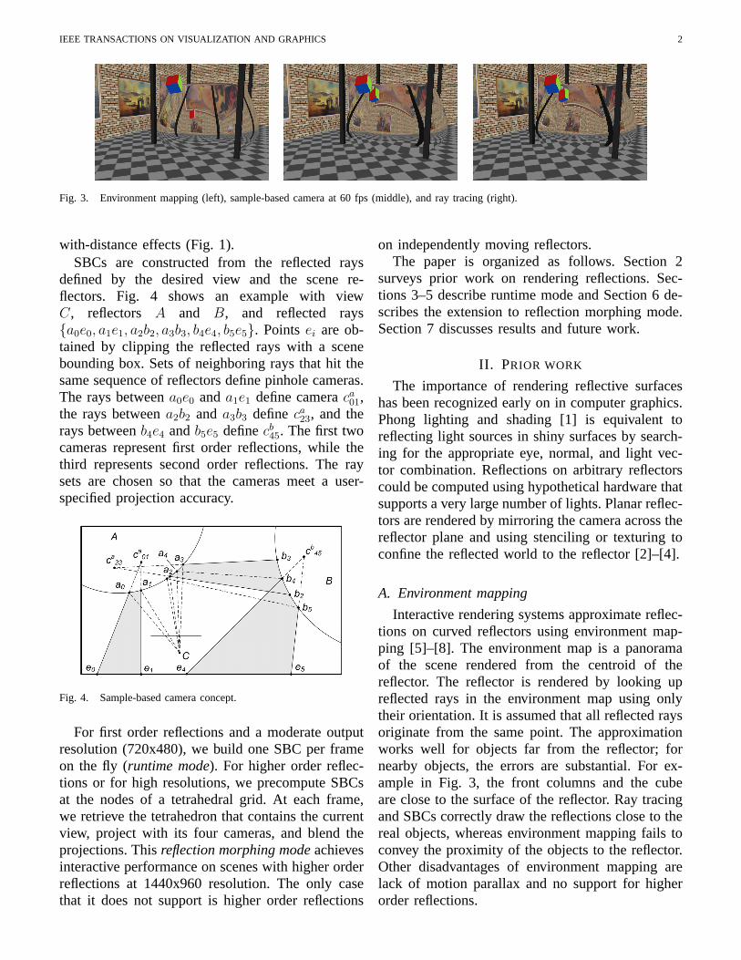
Fig. 3. Environment mapping (left), sample-based camera at 60 fps (middle), and ray tracing (right).
with-distance effects (Fig. 1).SBCs are constructed from the reflected rays
defined by the desired view and the scene re-flectors. Fig. 4 shows an example with viewC, reflectors A and B, and reflected rays{a0e0, a1e1, a2b2, a3b3, b4e4, b5e5}. Points ei are ob-tained by clipping the reflected rays with a scenebounding box. Sets of neighboring rays that hit thesame sequence of reflectors define pinhole cameras.The rays between a0e0 and a1e1 define camera ca
01,the rays between a2b2 and a3b3 define ca
23, and therays between b4e4 and b5e5 define cb
45. The first twocameras represent first order reflections, while thethird represents second order reflections. The raysets are chosen so that the cameras meet a user-specified projection accuracy.
Fig. 4. Sample-based camera concept.
For first order reflections and a moderate outputresolution (720x480), we build one SBC per frameon the fly (runtime mode). For higher order reflec-tions or for high resolutions, we precompute SBCsat the nodes of a tetrahedral grid. At each frame,we retrieve the tetrahedron that contains the currentview, project with its four cameras, and blend theprojections. This reflection morphing mode achievesinteractive performance on scenes with higher orderreflections at 1440x960 resolution. The only casethat it does not support is higher order reflections
on independently moving reflectors.The paper is organized as follows. Section 2
surveys prior work on rendering reflections. Sec-tions 3–5 describe runtime mode and Section 6 de-scribes the extension to reflection morphing mode.Section 7 discusses results and future work.
II. PRIOR WORK
The importance of rendering reflective surfaceshas been recognized early on in computer graphics.Phong lighting and shading [1] is equivalent toreflecting light sources in shiny surfaces by search-ing for the appropriate eye, normal, and light vec-tor combination. Reflections on arbitrary reflectorscould be computed using hypothetical hardware thatsupports a very large number of lights. Planar reflec-tors are rendered by mirroring the camera across thereflector plane and using stenciling or texturing toconfine the reflected world to the reflector [2]–[4].
A. Environment mapping
Interactive rendering systems approximate reflec-tions on curved reflectors using environment map-ping [5]–[8]. The environment map is a panoramaof the scene rendered from the centroid of thereflector. The reflector is rendered by looking upreflected rays in the environment map using onlytheir orientation. It is assumed that all reflected raysoriginate from the same point. The approximationworks well for objects far from the reflector; fornearby objects, the errors are substantial. For ex-ample in Fig. 3, the front columns and the cubeare close to the surface of the reflector. Ray tracingand SBCs correctly draw the reflections close to thereal objects, whereas environment mapping fails toconvey the proximity of the objects to the reflector.Other disadvantages of environment mapping arelack of motion parallax and no support for higherorder reflections.
IEEE TRANSACTIONS ON VISUALIZATION AND GRAPHICS 3
B. Projection methods
Better results can be obtained by solving theproblem of projecting reflected points. Hanrahanand Mitchell describe a search procedure for theprojection of reflected points if the reflector sur-face is given by an implicit equation [9]. Ofekand Rappoport [10] render reflections on tessellatedreflectors by projection followed by feed forwardrasterization. For each reflector, they compute areflection subdivision consisting of one cell per re-flector face. A scene point p is projected by findingits cell, interpolating the cell vertices to obtain anapproximate reflection point q and surface normaln, and mirroring the ray p−q around n. The reflec-tion subdivision is searched using an approximaterepresentation, called an explosion map.
Our algorithm has several advantages over Ofekand Rappaport, which is the closest prior work toours. SBCs project with high, guaranteed accuracyspecified by the user. The construction algorithmadaptively constructs a compact space partitioningthat achieves this accuracy for each frame basedon the view point and on the scene complexity.Explosion maps project approximately, at a fixedresolution without an error bound. We project higherorder reflections in the same way as first orderreflections, hence with the same cost and accuracy.Explosion maps render higher order reflections re-cursively, so the cost is proportional to the reflectionorder and the errors accumulate.
C. Image-based methods
The problem of reflections has also been studiedby researchers in image-based modeling and render-ing (IBMR). Light fields [11], [12] support view-dependent effects including reflections. A largenumber of rays need to be stored even for smallscenes. To alleviate this problem, IBMR techniqueswere developed that use some explicit form ofgeometry. Surface light fields store all rays origi-nating at each point of a surface [13], [14]. In viewdependent texture mapping, a surface is sampledfrom several directions [15], [16]. Both techniqueswork well for surfaces of limited specularity. Highlyreflective surfaces require a dense sampling of thepossible view directions, which translates into animpractical number of samples.
Lischinski [17] proposes a scene representationbased on layered depth images (LDIs) [18]. The
scene geometry is captured with a set of 3 orthog-onal LDIs. The view-dependent scene informationis stored in a light field of low resolution LDIs,which provides glossy reflections. Mirror-like re-flections are rendered by ray tracing the geometryLDIs, which alleviates the database size problembut reduces the performance below interactivity.Hakura [19] describes parameterized environmentmaps which are a set of precomputed referencereflection images. The images are parameterizedsuch that they best match in least-mean-squaressense the true reflection when used as environmentmaps. Good reflections are obtained nearby thereference viewpoints and rendering takes advantageof the hardware supported environment mapping.The method has the disadvantage of lengthy pre-processing (more than 20 minutes per viewpoint)which restricts its use to 1D parameterizations ofthe viewpoint space and to static scenes.
Like IBMR methods, the SBC approach usesdiscrete representations of functions that are difficultto compute, which are then interpolated. WhereasIBMR methods rely on sampling the plenoptic func-tion, SBCs sample the complex projection functionof vertices in scenes with reflectors. In this anal-ogy, the IBMR reference images correspond to theSBCs. Reference images become obsolete when adiffuse object moves and recomputing them requireshandling the scene at its full complexity. SBCs arebetter suited for rendering highly specular reflec-tions because they are independent of the diffusepart of the scene.
D. Hybrid methods
Between projection and IBMR, hybrid methodsseparate the geometry from the illumination of thereflector. Heidrich [20] captures the geometry of thereflector in a light field that maps rays to rays, ratherthan rays to colors. For a given view, the geometrylight field provides the reflected rays that are thencolored using an environment map, a regular lightfield, or ray tracing. The approach trades perfor-mance for accuracy. Cabral [21] combines BRDFswith lighting environments in precomputed radianceenvironment maps. Although hybrid methods allowone to modify the reflector and the illuminationindependently, they suffer from the other IBMRmethod disadvantages discussed above because theillumination is captured with images.
IEEE TRANSACTIONS ON VISUALIZATION AND GRAPHICS 4
E. Ray tracing
Reflections can be computed accurately using raytracing [22], [23], a general technique that produceshigh quality images. The ray tracing pipeline isless efficient than the feed forward pipeline becauseconsiderable computational effort has to be spentto decide which primitive affects a given outputimage pixel. Numerous research efforts are targetedat accelerating ray tracing. Wald [24], [25] hasdemonstrated real-time ray tracing on small sceneson a single general-purpose CPU with vector float-ing point extensions. Hardware has been developedto accelerate off-line ray tracing [26]. Complexscenes were ray traced at interactive rates on sharedmemory parallel computers [27] and on clusters[25]. The fixed function pipeline implemented incommodity graphics accelerators has been replacedwith a pipeline that offers programmability at thevertex and fragment levels. The programs that couldoriginally be executed to process vertices and frag-ments were too simple to implement ray tracing[28]. The programmability of GPUs has advancedsufficiently to allow limited ray tracing. But for theforeseeable future, GPUs will remain primarily feedforward rendering engines.
F. Non-pinhole camera models
Our solution for rendering reflections is based ona general, non-pinhole camera. Non-pinhole cameramodels have been studied in computer vision for 3Dimaging applications. Examples include the push-broom camera [29] and the two-slit camera [30],which are special cases of a linear camera [31] thatcollects linear combinations of three rays. A linearcamera cannot model the entire set of reflectedrays defined by a pinhole and a set of curvedreflectors. Computer graphics researchers have alsoexplored non-pinhole cameras. Other than the lightfield discussed above, examples include multiple-center-of-projection cameras [32], multiperspectivepanoramas for cel animation [33], and image-basedlenses for modeling real cameras [20]. None of theseare suitable for rendering reflections.
The image-based lens technique is related toSBCs. The rays exiting a real lens are approximatedwith a set of pinhole cameras. However, the scene isrendered with each pinhole camera and the imagesare blended together. This is appropriate for simu-lating real lens effects, such as non-zero aperture,
where the projection of a vertex is ambiguous. Butprojecting every vertex in every pinhole camera isprohibitive for interactive reflection rendering. Thecontribution of SBCs is to decompose a set ofreflected rays into a set of non-overlapping pinholecameras. This allows us to project reflected verticesquickly and thus to render reflections interactively.
III. ALGORITHM OVERVIEW
The input to our reflection rendering algorithmis a scene description, a desired view, a reflectionorder cutoff, a down-sampling factor, and a projec-tion accuracy in desired image pixels. The sceneconsists of diffuse and reflective objects modeledwith triangle meshes. Fig. 5 shows the main stepsof the algorithm.
render reflections
SBCbuild
meshesrender
reflected raysgenerate
Fig. 5. Algorithm overview.
A. Render meshes
The reflective and diffuse meshes are renderedin hardware with z-buffering. Diffuse meshes arerendered as usual to generate their final image.Reflective meshes are rendered in the stencil buffer.The stencil is set to the id of the reflector to confinethe reflection to the visible part of the reflector.Fig. 6 (left) illustrates this step on a scene with twospherical reflectors.
Fig. 6. Frame buffer after mesh rendering with non-zero stencilvalues visualized in yellow (left). First order (top) and second order(bottom) reflected rays.
IEEE TRANSACTIONS ON VISUALIZATION AND GRAPHICS 5
B. Generate reflected rays
Reflected rays are generated from the desiredview. The reflected rays are stored in a 2D map,which is typically down-sampled to half or quarterdesired image resolution. Fig. 6 (right) shows ahalf resolution ray map with first and second orderrays. A ray is represented by its tail, head, and firstreflector point; these are [a1, e1, a1], [a3, b3, a3], and[b4, e4, a4] in Fig. 4. First order rays are computedon the GPU. Higher order rays are computed byray tracing the reflectors alone, without the diffuseobjects. Thus, the cost is proportional to the reflectorcomplexity, which is typically a small fraction of thescene complexity.
C. Build cameras and render reflections
Section 4 describes how SBCs are built from theray map and Section 5 describes how they are usedto render reflections. Fig. 7 shows the output.
Fig. 7. Output image (top) and ray traced image (bottom).
IV. SAMPLE-BASED CAMERA CONSTRUCTION
An SBC defines a mapping from a scene point toits reflections in the desired view. The SBC is builtfrom the ray map. The rays are first partitioned intoreflection groups. A reflection group R1R2 · · ·Rn
comprises all the rays with the same reflectionhistory. The reflection history of a reflected ray ris the list of reflectors encountered by the desiredview ray that generates r. A projection function iscomputed for each reflection group. For examplein Fig. 8, p is projected to first reflector point a1
in reflection group A and to a2 in AB. The SBCmapping is the union of the projection functions ofits reflection groups.
Fig. 8. Sample-based camera projection.
A reflection group projection function is definedby a set of pinhole cameras whose frustums en-compass the rays of the group. Our example showsa camera for the AB reflection group with centerof projection cb, image plane b0b1, and frustume0b0b1e1. A scene point is handled by the camerawhose frustum contains it: the point is projectedonto the camera image plane then is mapped tothe first reflector. The example camera projects pto b2 on image plane b0b1 then maps b2 to a2 on A.A scene point that is not contained in any camerafrustum does not project.
A camera is constructed for a set of rays asfollows. The center of projection, o, is the least-squares fit of a point that lies on the rays. Theequation for a ray with tail t and direction vector dis o×d = t×d, which yields three scalar equationsin ox, oy, oz. The image plane is fitted to the raytails. The view frustum is chosen to contain thetails and the heads. The mapping from the imageplane to the first reflector is a quadratic, f(u, v),that is constructed by least-squares fitting the raysto their first reflector points. Each ray generates theequations f(ut, vt) = q and f(uh, vh) = q in whichq is the first reflector point and (ut, vt) and (uh, vh)are the tail and head image plane projections.
The cameras are stored in the leaves of a BSP tree[34]. Fig. 9 shows the BSP tree for the A reflection
IEEE TRANSACTIONS ON VISUALIZATION AND GRAPHICS 6
group of Fig. 8. It has 6 internal nodes with splittingplanes 0–5 and stores cameras c0–c6 at its 7 leaves.
A reflection group is decomposed into a BSP treeof cameras by the algorithm in Fig. 10. The firststep is to fit a camera to the set of rays in thegroup. If the fit is accurate, the camera is stored ina leaf node. The approximation error is estimatedas the maximum error at the heads and tails of therays. This error is the distance in pixels between theprojections onto the desired view of the true andapproximate first reflection points. If the fit fails,a plane is chosen heuristically to split the inputroughly in half. It passes through the centroid ofthe ray tails, is parallel to the mean reflected raydirection, and is perpendicular to the diameter ofthe tails. The rays that intersect the positive/negativehalf spaces are assigned to the left/right subsets. Aray is assigned to both subsets if its unit frustumintersects the plane. The unit frustum of ray (u, v)in ray map coordinates is the set of four rays(u ± 1, v ± 1). For example, the overlap betweencameras c3 and c4 in Fig. 9 is due to the unit frustumthat intersects plane 4. Splitting fails when eithersubset equals the input set; the rays are stored in alist at the leaf. Otherwise, the recursive case occurs.
The first reflector point of scene point p is foundby first traversing the BSP tree to find the leafthat contains p. If the leaf contains a camera, thefirst reflector point is computed by the two-stepprocedure above. If the leaf contains a ray list, theunit frustum that contains p is found and the firstreflector points of its rays are interpolated.
V. RENDERING REFLECTIONS
A reflection is generated for every diffuse objectin every reflection group. The diffuse meshes areprojected into the desired view then are rasterizedin hardware.
Fig. 11. Visibility cases.
A. Projection
A diffuse mesh vertex is projected into a reflec-tion group by computing the first reflection pointthen offsetting along the desired view ray for correctvisibility. Fig. 11 shows the visibility ordering alonga reflection path from C to A to B and beyond.There are three visibility cases.
1) The closest scene point or reflector surface isvisible (v0
0 occludes a, which occludes v01).
2) Within a reflection group, the point closest tothe last reflector surface is visible (v1
0 occludesv1
1).3) Between reflection groups, lower order points
are visible (v11 occludes v2
0).Case 1 is handled by z-buffering in Section III-A. Cases 2 and 3 are handled by offsetting thefirst reflector point (a) along its desired view ray(ca). For a k-order reflection of v, the offset is(k − 1 + z/D)g where z is the distance from v tothe reflection camera image plane, D is the scenediameter, and g is the depth range per reflectionorder. We choose g equal to D/(kmax + 1) and setyon to 2D.
IEEE TRANSACTIONS ON VISUALIZATION AND GRAPHICS 7
Fig. 12. Jagged reflection edges (left) alleviated by subdivision(middle, right).
B. Rasterization
A triangle is rendered when all three verticesproject and is discarded when none project. A trian-gle is called mixed when one or two vertices project.Discarding mixed triangles creates jagged reflectionedges. We solve this problem by subdividing mixedtriangles whose area exceeds a threshold (Fig. 12).
When a reflected triangle is rasterized, its true,curved edges are approximated with straight edges.This approximation is acceptable only for smalltriangles. As a preprocess, we subdivide the scenetriangles to limit the edge lengths.
C. Lighting and shading
SBCs render reflections by computing a reflectedmesh for each diffuse mesh. The reflected mesh isplaced and distorted to form the correct reflectionwhen seen from the desired view. Lighting andshading that does not depend on the vertex sceneposition (lighting baked into vertex colors, diffusedirectional lighting, and texture mapping) is unaf-fected by reflection and is carried out with the data(vertex colors, texture coordinates, normals) usedfor the unreflected mesh.
We support point light sources and specular light-ing with GPU shaders that take into account theoriginal position of the reflected vertices and thetrue eye vector. Fig. 13 shows a scene with a pointlight source L that is rendered with our method. Thesphere D has a specular highlight at hD, whereas itsreflection on R has a highlight at hRD. The mirrorhas a specular highlight at hR. The eye vector athRD is given by p− hRD and not by C − hRD. Thehighlights on the sphere correctly occur at differentlocations.
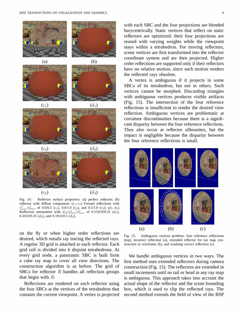
D. Reflector surface properties
SBCs provide a projection function for verticesthat reflect from curved surfaces. This allows us
Fig. 13. Reflection with specular lighting.
to compute reflections by feed-forward renderingthe reflected objects, which was previously possibleonly for planar reflectors. Because of the feed-forward approach, SBCs handle perfect, mirror-likereflectors directly (Fig. 14a). Such reflectors arechallenging because reflection artifacts stand outand because they require a high sampling density inthe case of image-based reflection rendering meth-ods (light fields, view-dependent texture mapping).
Reflectors with a diffuse component are readilyhandled in the SBC framework. The diffuse com-ponent and the reflection are blended with a simpleshader. The images ci in Fig. 14 show Fresnelreflections with blending weights proportional to thesquare of the dot product of the eye vector and thesurface normal. The weights are scaled linearly tothe specularity interval [sf
min, sfmax]. In images di,
the reflection weight is attenuated with the squareof the distance between the reflected object and thereflector surface. This distance is already computedduring SBC projection for visibility purposes. Asthe distance increases from 0 to dM , the specular-ity decreases quadratically between sa
max and samin.
Fig. 14b combines the two effects.
E. Antialiasing
Curved reflectors considerably minify distantparts of the scene, which makes the problem ofantialiasing challenging in ray tracing, particularlyfor higher order reflections when the angle betweenneighboring rays grows large. Rendering reflectionswith the feed forward approach simplifies antialias-ing. Each triangle is processed, which eliminates thedanger of sub-sampling the geometry, and texturesare correctly minified by mip-mapping.
VI. REFLECTION MORPHING
We switch to reflection morphing mode whenthe ray map is too large for us to build the SBC
min/sfmax of 0.0/0.5 (c1), 0.0/1.0 (c2), and 0.5/1.0 (c3); (d1–d3)
Reflection attenuation with dM /samin/sa
min of 0.15/0.0/0.25 (d1),0.3/0.0/0.25 (d2), and 0.3/0.0/0.5 (d3).
on the fly or when higher order reflections aredesired, which entails ray tracing the reflected rays.A regular 3D grid is attached to each reflector. Eachgrid cell is divided into 6 disjoint tetrahedrons. Atevery grid node, a panoramic SBC is built froma cube ray map to cover all view directions. Theconstruction algorithm is as before. The grid ofSBCs for reflector R handles all reflection groupsthat begin with R.
Reflections are rendered on each reflector usingthe four SBCs at the vertices of the tetrahedron thatcontains the current viewpoint. A vertex is projected
with each SBC and the four projections are blendedbarycentrically. Static vertices that reflect on staticreflectors are optimized: their four projections arereused with varying weights while the viewpointstays within a tetrahedron. For moving reflectors,scene vertices are first transformed into the reflectorcoordinate system and are then projected. Higherorder reflections are supported only if their reflectorshave no relative motion, since such motion rendersthe reflected rays obsolete.
A vertex is ambiguous if it projects in someSBCs of its tetrahedron, but not in others. Suchvertices cannot be morphed. Discarding triangleswith ambiguous vertices produces visible artifacts(Fig. 15). The intersection of the four referencereflections is insufficient to render the desired viewreflection. Ambiguous vertices are problematic atcurvature discontinuities because there is a signifi-cant disparity between the four reference reflections.They also occur at reflector silhouettes, but theimpact is negligible because the disparity betweenthe four reference reflections is small.
(a) (b) (c)
Fig. 15. Ambiguous vertices problem: four reference reflections(top), incorrect reflection (a), extended reflector for ray map con-struction in wireframe (b), and resulting correct reflection (c).
We handle ambiguous vertices in two ways. Thefirst method uses extended reflectors during cameraconstruction (Fig. 15). The reflectors are extended insmall increments until no tail or head in any ray mapis ambiguous. This approach takes into account theactual shape of the reflector and the scene boundingbox, which is used to clip the reflected rays. Thesecond method extends the field of view of the BSP
IEEE TRANSACTIONS ON VISUALIZATION AND GRAPHICS 9
leaf cameras, which provides projections for pointsoutside the ray maps.
VII. DISCUSSION
We conclude the paper with results on the qualityand speed of sample-based cameras followed byplans for future work.
A. Quality
Rendering reflections with an SBC entails ap-proximations in the projection of reflected verticesand in the rasterization of reflected triangles.
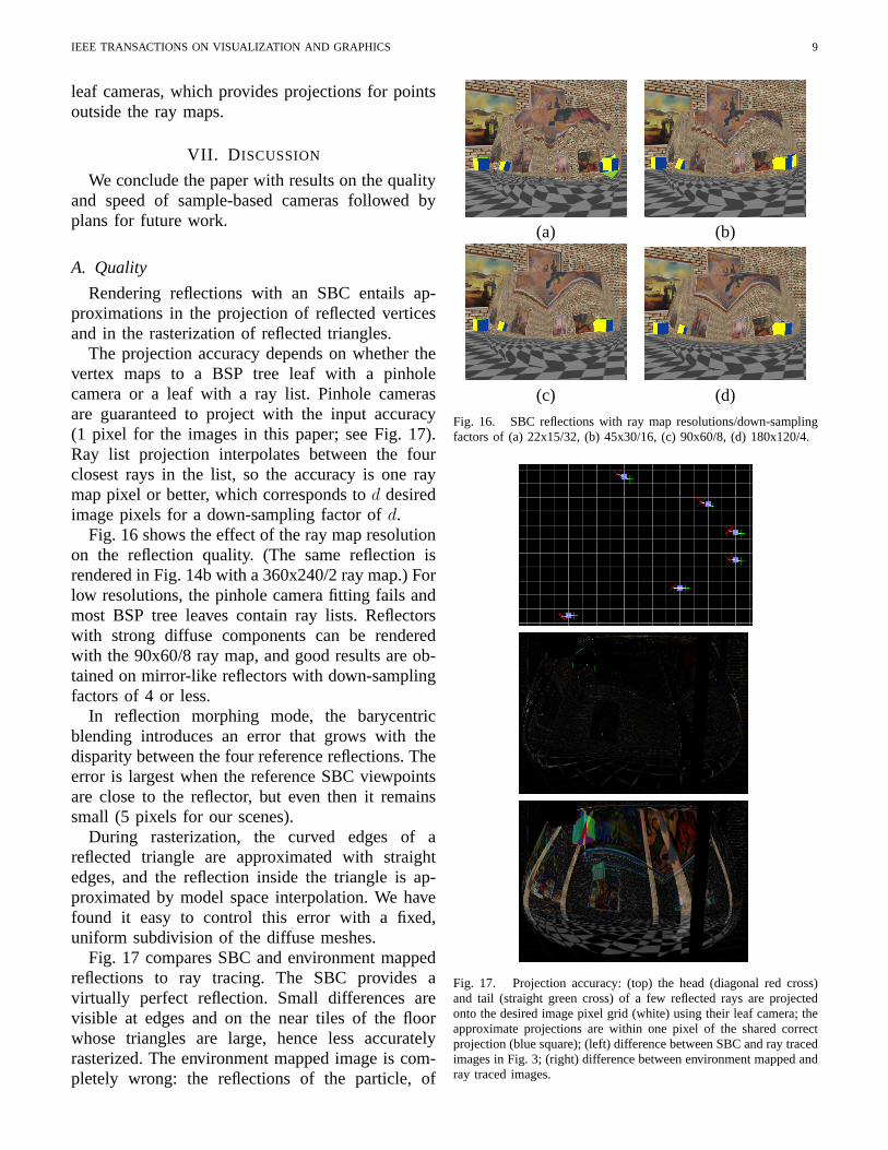
The projection accuracy depends on whether thevertex maps to a BSP tree leaf with a pinholecamera or a leaf with a ray list. Pinhole camerasare guaranteed to project with the input accuracy(1 pixel for the images in this paper; see Fig. 17).Ray list projection interpolates between the fourclosest rays in the list, so the accuracy is one raymap pixel or better, which corresponds to d desiredimage pixels for a down-sampling factor of d.
Fig. 16 shows the effect of the ray map resolutionon the reflection quality. (The same reflection isrendered in Fig. 14b with a 360x240/2 ray map.) Forlow resolutions, the pinhole camera fitting fails andmost BSP tree leaves contain ray lists. Reflectorswith strong diffuse components can be renderedwith the 90x60/8 ray map, and good results are ob-tained on mirror-like reflectors with down-samplingfactors of 4 or less.
In reflection morphing mode, the barycentricblending introduces an error that grows with thedisparity between the four reference reflections. Theerror is largest when the reference SBC viewpointsare close to the reflector, but even then it remainssmall (5 pixels for our scenes).
During rasterization, the curved edges of areflected triangle are approximated with straightedges, and the reflection inside the triangle is ap-proximated by model space interpolation. We havefound it easy to control this error with a fixed,uniform subdivision of the diffuse meshes.
Fig. 17 compares SBC and environment mappedreflections to ray tracing. The SBC provides avirtually perfect reflection. Small differences arevisible at edges and on the near tiles of the floorwhose triangles are large, hence less accuratelyrasterized. The environment mapped image is com-pletely wrong: the reflections of the particle, of
(a) (b)
(c) (d)
Fig. 16. SBC reflections with ray map resolutions/down-samplingfactors of (a) 22x15/32, (b) 45x30/16, (c) 90x60/8, (d) 180x120/4.
Fig. 17. Projection accuracy: (top) the head (diagonal red cross)and tail (straight green cross) of a few reflected rays are projectedonto the desired image pixel grid (white) using their leaf camera; theapproximate projections are within one pixel of the shared correctprojection (blue square); (left) difference between SBC and ray tracedimages in Fig. 3; (right) difference between environment mapped andray traced images.
IEEE TRANSACTIONS ON VISUALIZATION AND GRAPHICS 10
the columns, and of the part of the floor near thereflector are tens to hundreds of pixels from theircorrect locations.
B. Speed
The reflection rendering time goes to ray mapgeneration, SBC construction, and vertex projection.
Ray map generation: Maps of first-order re-flected rays are generated in hardware by renderingthe surfaces of the reflectors with a GPU programthat encodes the direction (two fractional numbers)in the four color bytes. Z, color, and stencil are readback to obtain the tails, heads, and reflector idsof the reflected rays. 360x240/180x120 ray mapsare generated in 27ms/9ms when every ray hitsa reflector (the entire desired view is covered byreflectors). Timing data was obtained on a 3.4GHz3GB Pentium 4 Xeon PC with a 256MB QuadroFX 3400 NVIDIA graphics card. The time neededto trace higher order reflected rays depends on thecomplexity of the reflector.
SBC construction: The splitting plane heuris-tic generates balanced trees for our test scenes.Constructing a balanced BSP tree from n inputreflected rays takes n log n time and the traversalto find the first reflector point takes log n time.Fig. 19 gives SBC construction statistics for thereflectors and the views shown in Figs. 18, 14, 7,and 1. Each table entry is split in two: the left/rightfigures are for a quarter/half resolution ray map. TheSBCs have a maximum size of a few MB; SBCconstruction performance is 10–15 Hz when usingquarter resolution ray maps.
Fig. 18. Sample reflection.
In reflection morphing mode, we construct theSBCs as a preprocess. A 17x17 layer of the 17x17x8grid used for our test scene is computed in an hour.Two layers fit in memory and are loaded at startup.
Fig. 19. SBC construction performance for four test scenes.
Vertex projection: In run time mode, vertexprojection is performed in hardware. After the BSPis computed on the CPU, the BSP trees are packedand loaded into texture memory using the vertextexture technique. The vertex program first executesa loop that finds the leaf to which the vertex belongs.If no leaf is found, the vertex is discarded. Once theleaf is known, its data is used to move the vertexto the offset first reflector point. The average vertexprojection performance is 20 million vertices persecond (Mv/s) for pinhole camera leaves and 2.5Mv/s for ray list leaves. Compared to projectingon the CPU, the GPU brings a 5 fold speedup.The longer ray list time is due to the sequentialprocessing of the rays.
In reflection morphing mode, the projection isperformed on the CPU and the projections of staticvertices are reused. The average static/dynamic ver-tex projection performance is 12.5/1 Mv/s.
Overall performance: In run-time mode, per-formance is dictated by SBC construction. The au-tomobile and teapot body scenes are rendered withaverage frame rates of 6 and 8 Hz, and the bunnyis rendered at 15 fps. In reflection morphing mode,performance is dictated by the number of vertices.The teapot body and two spheres scenes have 10,000vertices (20,000 triangles) and are rendered at 60/30fps for 720x480/1440x960 output resolutions.
C. Compound reflectors
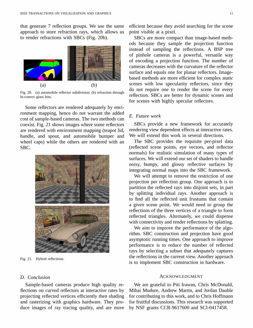
SBCs assume that each scene point has at mostone reflection in each reflection group. This con-dition is satisfied if the rays of a reflection groupdo not intersect inside the scene volume. Convexreflectors satisfy this condition. We can handle con-cave reflectors when we can split them into pieceswhose rays do not intersect. Fig. 1 was rendered bysubdividing the automobile into 7 parts (Fig. 20a)
IEEE TRANSACTIONS ON VISUALIZATION AND GRAPHICS 11
that generate 7 reflection groups. We use the sameapproach to store refraction rays, which allows usto render refractions with SBCs (Fig. 20b).
Some reflectors are rendered adequately by envi-ronment mapping, hence do not warrant the addedcost of sample-based cameras. The two methods cancoexist. Fig. 21 shows images where some reflectorsare rendered with environment mapping (teapot lid,handle, and spout, and automobile bumper andwheel caps) while the others are rendered with anSBC.
Fig. 21. Hybrid reflections.
D. Conclusion
Sample-based cameras produce high quality re-flections on curved reflectors at interactive rates byprojecting reflected vertices efficiently then shadingand rasterizing with graphics hardware. They pro-duce images of ray tracing quality, and are more
efficient because they avoid searching for the scenepoint visible at a pixel.
SBCs are more compact than image-based meth-ods because they sample the projection functioninstead of sampling the reflections. A BSP treeof pinhole cameras is a powerful, versatile wayof encoding a projection function. The number ofcameras decreases with the curvature of the reflectorsurface and equals one for planar reflectors. Image-based methods are more efficient for complex staticscenes with low specularity reflectors, since theydo not require one to render the scene for everyreflection. SBCs are better for dynamic scenes andfor scenes with highly specular reflectors.
E. Future work
SBCs provide a new framework for accuratelyrendering view dependent effects at interactive rates.We will extend this work in several directions.
The SBC provides the requisite per-pixel data(reflected scene points, eye vectors, and reflectornormals) for realistic simulation of many types ofsurfaces. We will extend our set of shaders to handlenoisy, bumpy, and glossy reflective surfaces byintegrating normal maps into the SBC framework.
We will attempt to remove the restriction of oneprojection per reflection group. One approach is topartition the reflected rays into disjoint sets, in partby splitting individual rays. Another approach isto find all the reflected unit frustums that containa given scene point. We would need to group thereflections of the three vertices of a triangle to formreflected triangles. Alternately, we could dispensewith connectivity and render reflections by splatting.
We aim to improve the performance of the algo-rithm. SBC construction and projection have goodasymptotic running times. One approach to improveperformance is to reduce the number of reflectedrays by selecting a subset that adequately capturesthe reflections in the current view. Another approachis to implement SBC construction in hardware.
ACKNOWLEDGMENT
We are grateful to Piti Irawan, Chris McDonald,Mihai Mudure, Andrew Martin, and Jordan Daublefor contributing to this work, and to Chris Hoffmannfor fruitful discussions. This research was supportedby NSF grants CCR-9617600 and SCI-0417458.
IEEE TRANSACTIONS ON VISUALIZATION AND GRAPHICS 12
REFERENCES
[1] B. Phong, “Illumination for computer-generated images,” Ph.D.dissertation, University of Utah, 1973.
[2] P. J. Diefenbach, “Pipeline rendering: Interaction and realismthrough hardware-based multi-pass rendering,” Ph.D. disserta-tion, University of Pennsylvania, 1996.
[3] T. Mcreynolds and D. Blythe, “Programming with opengl:Advanced rendering,” 1997, sIGGRAPH 97 course.
[4] R. Bastos, K. Hoff, W. Wynn, and A. Lastra, “Increasedphotorealism for interactive architectural walkthroughs,” in In-teractive 3D Graphics, 1999, pp. 183–190.
[5] J. Blinn and M. Newell, “Texture and reflection in computergenerated images,” Communications of the ACM, vol. 19,no. 10, pp. 542–547, 1976.
[6] N. Greene, “Environment mapping and other applications ofworld projections,” IEEE Computer Graphics and Applications,vol. 6, no. 11, pp. 21–29, 1986.
[7] P. Haeberli and M. Segal, “Texture mapping as a fundamentaldrawing primitive,” in Proceedings of the Fourth EurographicsWorkshop on Rendering, S. Cohen, Puech, Ed., 1993, pp. 259–266.
[8] D. Voorhies and J. Foran, “Reflection vector shading hardware,”in Proceedings of ACM SIGGRAPH. ACM Press, 1994, pp.163–166.
[9] H. P. and D. Mitchell, “Illumination from curved reflectors,”in Proceedings of ACM SIGGRAPH. ACM Press, 1992, pp.283–291.
[10] E. Ofek and A. Rappoport, “Interactive reflections on curvedobjects,” in Proceedings of ACM SIGGRAPH. ACM Press,1998, pp. 333–342.
[11] M. Levoy and P. Hanrahan, “Light field rendering,” in Proceed-ings of ACM SIGGRAPH. ACM Press, 1996, pp. 31–42.
[12] S. Gortler, R. Grzeszczuk, R. Szeliski, and M. Cohen, “Thelumigraph,” in Proceedings of ACM SIGGRAPH. ACM Press,1996, pp. 43–54.
[13] G. S. P. Miller, S. M. Rubin, and D. Ponceleon, “Lazy de-compression of surface light fields for precomputed globalillumination,” in Eurographics Workshop on Rendering, 1998.
[14] D. N. Wood, D. I. Azuma, K. Aldinger, B. Curless, T. Duchamp,D. H. Salesin, and W. Stuetzle, “Surface light fields for 3dphotography,” in Proceedings of ACM SIGGRAPH. ACMPress, 2000, pp. 287–296.
[15] P. Debevec, Y. Yu, and G. Borshukov, “Efficient view-dependentimage-based rendering with projective texture-mapping,” inProceedings of the 9th Eurographics Workshop on Rendering,1998, pp. 105–116.
[16] K. Pulli, M. Cohen, T. Duchamp, H. Hoppe, L. Shapiro, andW. Stuetzle, “View-based rendering: Visualizing real objectsfrom scanned range and color data,” in Eurographics RenderingWorkshop, 1997, pp. 23–34.
[17] D. Lischinski and A. Rappoport, “Image-based rendering fornon-diffuse synthetic scenes,” in Eurographics Rendering Work-shop, 1998, pp. 301–314.
[18] J. Shade, S. Gortler, L. He, and R. Szeliski, “Layered depthimages,” in Proceedings of ACM SIGGRAPH. ACM Press,1998, pp. 231–242.
[19] Z. Hakura, J. Snyder, and J. Lengyel, “Parameterized envi-ronment maps,” in Proceedings of the ACM Symposium onInteractive 3D Graphics, 2001, pp. 203–208.
[20] W. Heidrich, H. Lensch, M. Cohen, and H. Seidel, “Lightfield techniques for reflections and refractions,” in EurographicsRendering Workshop, 1999, pp. 195–375.
[21] B. Cabral, M. Olano, and P. Nemec, “Reflection space imagebased rendering,” in Proceedings of ACM SIGGRAPH. ACMPress, 1999, pp. 165–170.
[22] T. Whitted, “An improved illumination model for shaded dis-play,” Communications of the ACM, vol. 23, no. 6, pp. 343–349,1980.
[23] A. Glassner, An introduction to ray tracing. Academic Press,1989.
[24] I. Wald, P. Slussalek, and C. Benthin, “Interactive distributedray tracing of highly complex models,” in Rendering Techniques2001: 12th Eurographics Workshop on Rendering, 2001, pp.277–288.
[25] I. Wald, P. Slusallek, C. Benthin, and M. Wagner, “Interactiverendering with coherent ray tracing,” Computer Graphics Fo-rum, vol. 20, no. 3, pp. 153–164, 2001.
[26] D. Hall, “The ar350: Today’s ray trace rendering processor,” inSIGGRAPH/Eurographics Workshop On Graphics Hardware.ACM Press, 2001.
[27] S. Parker, W. Martin, P. Sloan, P. Shirley, B. Smits, andC. Hansen, “Interactive ray tracing,” in ACM Symposium onInteractive 3D Graphics, 1999, pp. 119–126.
[28] T. J. Purcell, I. Buck, W. R. Mark, and P. Hanrahan, “Raytracing on programmable graphics hardware,” in Proceedingsof ACM SIGGRAPH, vol. 21, no. 3. ACM Press, 2002, pp.703–712.
[29] R. Gupta and R. I. Hartley, “Linear pushbroom cameras,” IEEETransactions on Pattern Analysis and Machine Intelligence,vol. 19, no. 9, pp. 963–975, 1997.
[30] T. Pajdla, “Geometry of two-slit camera,” Czech TechnicalUniversity, Tech. Rep. 2002-02, 2002.
[31] Y. J. and M. L., “General linear cameras,” in 8th EuropeanConference on Computer Vision, vol. 2, 2004, pp. 14–27.
[32] P. Rademacher and G. Bishop, “Multiple-center-of-projectionimages,” in Proceedings of ACM SIGGRAPH. ACM Press,1998, pp. 199–206.
[33] D. N. Wood, A. Finkelstein, J. F. Hughes, C. E. Thayer, andD. H. Salesin, “Multiperspective panoramas for cel animation,”in Proceedings of ACM SIGGRAPH. ACM Press, 1997, pp.243–250.
[34] H. Fuchs, Z. Kedem, and B. Naylor, “On visible surfacegeneration by a priori tree structures,” in Proceedings of ACMSIGGRAPH. ACM Press, 1980, pp. 124–133.
Voicu Popescu is an assistant professor of computer science atPurdue. He received his Ph.D. in 2001 from the University of NorthCarolina at Chapel Hill. His research interests lie in the areas ofcomputer graphics, computer vision, and visualization.
Elisha Sacks is a professor of computer science at Purdue. Hereceived his Ph.D. in 1988 from MIT under Gerald Sussman andRamesh Patil. His research interests are geometric computing, scien-tific and engineering problem solving, mechanical design automation,and robotics.
Chunhui Mei is a postdoc in the Purdue computer science depart-ment.