18
Copyright Nistune Developments 2014-2019 rev6

Copyright Nistune Developments 2014-2019 rev6

Table of Contents
1. Factory Boost Sensor Setup and Adjustment .................................................................................................. 3
2. Boost Sensor (removed – Option 1) ................................................................................................................ 5
3. Boost Sensor (removed – Option 2) ................................................................................................................ 6
4. TP Load Register (BFuel Schedule) ............................................................................................................... 9
5. Fuel maps ...................................................................................................................................................... 10
6. AlphaN/Increase Fuel (vs TPS) .................................................................................................................... 11
7. Throttle Enrich (VE) Map ............................................................................................................................. 12
8. Removing traction control............................................................................................................................. 13
9. Feedback Control Flags ................................................................................................................................. 14
10. Fan Control Table ...................................................................................................................................... 15
11. Appendix: Throttle Enrich indexing .......................................................................................................... 16
12. Appendix: Air conditioning (transplants) .................................................................................................. 18

1.1.1.1. Factory BFactory BFactory BFactory Boost Sensoroost Sensoroost Sensoroost Sensor Setup and AdjustmentSetup and AdjustmentSetup and AdjustmentSetup and Adjustment
Nissan has added a boost sensor to the Nissan ECU for NEO engines. Ensure the boost sensor connected as per the below diagram:
If using an aftermarket plenum / throttle body without the TCS, ensure the boost sensor is still plumbed before the throttle body. If plumbed incorrectly you may experience throttle response issues. Boost pressure sensor. Uses a vaccum/boost equipped MAP sensor capable of measuring up to 5.12 volts at 18psi. To view the boost pressure enable this consult register. Nistune will display the value in volts and PSI on the gauges.
Boost Pressure Sensor Gauges
If the boost sensor voltage exceeds the specified max voltage 4.84 volts (4840mv) the Boost Sensor DTC
code will be raised. . This is about 16-17psi. Adjust the max boost voltage to 5120mV to avoid this.

Next increase your boost sensor fuel cut table. These are used instead of TP limit tables during normal operation
• Increasing the values of these tables to a maximum of 5100 millivolts will work upto 18psi for safely limiting boost levels.
Note: 5100mV = 18 psi, 4340mV = 12 psi
• Above 18 psi to increase the Boost sensor limit counter adjusting the time over 18psi before the ECU performs a fuel cut
Note: Maximum of 255 will effectively disable the cut completely Important note: When the boost sensor is disconnected, and there is a Boost Sensor DTC fault code, the ECU will instead use the TP limit tables and counter (see further)
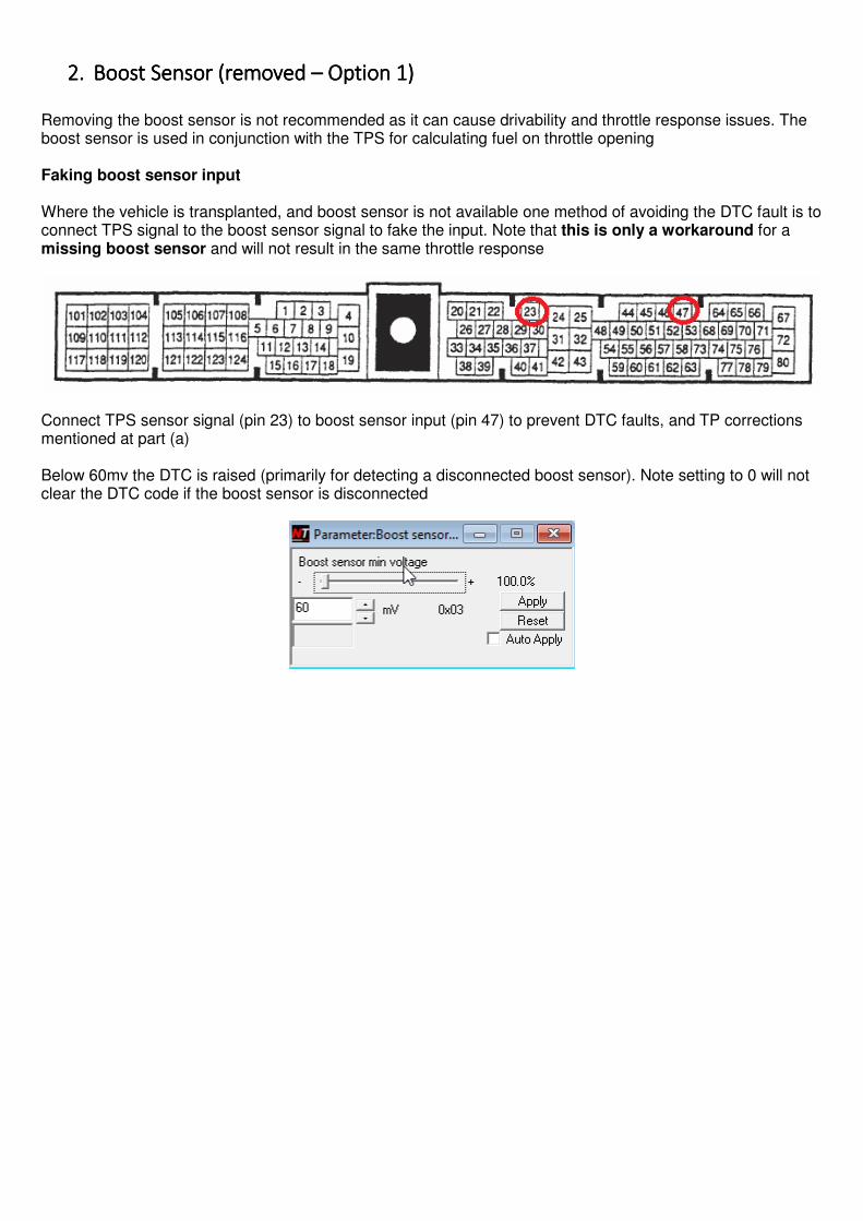
2.2.2.2. Boost SensorBoost SensorBoost SensorBoost Sensor (removed(removed(removed(removed –––– Option Option Option Option 1111))))
Removing the boost sensor is not recommended as it can cause drivability and throttle response issues. The boost sensor is used in conjunction with the TPS for calculating fuel on throttle opening Faking boost sensor input Where the vehicle is transplanted, and boost sensor is not available one method of avoiding the DTC fault is to connect TPS signal to the boost sensor signal to fake the input. Note that this is only a workaround for a missing boost sensor and will not result in the same throttle response
Connect TPS sensor signal (pin 23) to boost sensor input (pin 47) to prevent DTC faults, and TP corrections mentioned at part (a) Below 60mv the DTC is raised (primarily for detecting a disconnected boost sensor). Note setting to 0 will not clear the DTC code if the boost sensor is disconnected

3.3.3.3. Boost SensorBoost SensorBoost SensorBoost Sensor (removed(removed(removed(removed –––– Option Option Option Option 2222))))
1. Running without a boost sensor (not recommended) requires some changes to parameters.
(a) Disconnecting the MAP sensor wiring will raise a boost sensor DTC fault code and will result in problems
Unticking DTC fault filters for the boost sensor to remove the DTC fault and check engine light
This will put the ECU in a boost limp state and have effects on TP
(b) Disconnecting the MAP sensor hose results in using a default voltage of 2.70 volts and will not raise fault codes, but still will result in problems.
2. You must map the ECU TP load scales under 132 to ensure that a lean condition is not reached: Both sets of scales must be remapped to 132 maximum:
Adjust both sets of TP scales, by setting 132 maximum and then interpolate. Do the same for timing by ‘Copy to partner’ from the fuel load scale.

After adjusting the scales, you may need to also adjust the TP multiplier (K constant) so that your fuel maptrace runs within your new scales (upto TP=132)
If you have TP overshooting the updated scalers (say 30% over), then drop K Constant by about this percentage, and then increase your TIM by the same amount to keep the same fueling. Base fueling should be stoich during cruise conditions (near 0% STFT and LTFT) We do this since running without a working boost sensor will affect injection when TP is over 132 and the throttle is lifted causing a lean condition
Steady RPM (red) and increasing MAF (blue) but the slight decrease in throttle position (green) the Nissan ECU has drops the TP load (purple) and resulting injeciton pulsewidth (yellow) resulting in a lean condition. Nissan NEO ECUs will trigger a sharp drop in TP when the MAP sensor does not report valid boost readings.

Rescale upto maximum TP of 132 to aovid this issue when the boost sensor is not connected/working 3. With the boost sensor disabled, the TP cut limit tables and counter are instead used and must be
increased where required

4.4.4.4. TP Load RegisteTP Load RegisteTP Load RegisteTP Load Registerrrr (BFuel Schedule)(BFuel Schedule)(BFuel Schedule)(BFuel Schedule) BFuel Schedule (Theoretical Pulsewidth) is the replacement TP (load) parameter used with NEO ECUs.
Consult Register Selection
This parameter used for maptracing the columns on the fuel and timing maps and is a preliminary calculation used for final injection. Right click the background of Nistune and ‘Select Channels’ to show this screen
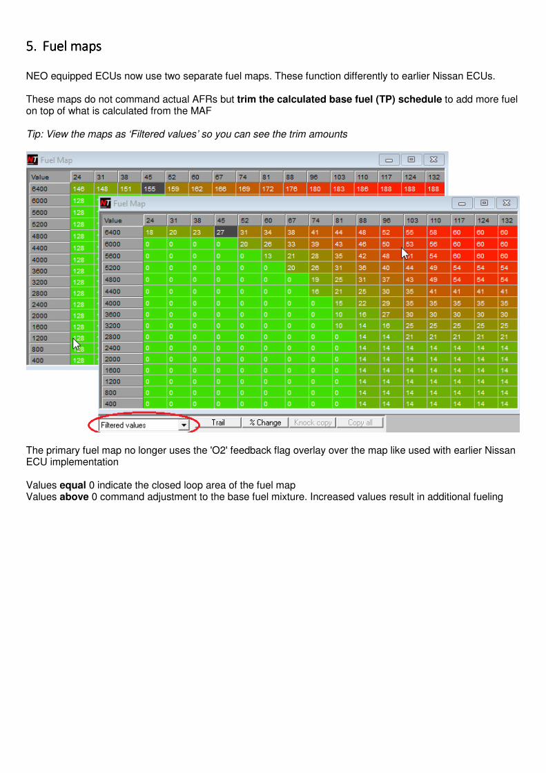
5.5.5.5. Fuel mapsFuel mapsFuel mapsFuel maps
NEO equipped ECUs now use two separate fuel maps. These function differently to earlier Nissan ECUs. These maps do not command actual AFRs but trim the calculated base fuel (TP) schedule to add more fuel on top of what is calculated from the MAF Tip: View the maps as ‘Filtered values’ so you can see the trim amounts
The primary fuel map no longer uses the 'O2' feedback flag overlay over the map like used with earlier Nissan ECU implementation Values equal 0 indicate the closed loop area of the fuel map Values above 0 command adjustment to the base fuel mixture. Increased values result in additional fueling

6.6.6.6. AlphaN/Increase Fuel (vs TPS)AlphaN/Increase Fuel (vs TPS)AlphaN/Increase Fuel (vs TPS)AlphaN/Increase Fuel (vs TPS) The Alpha/N table functions the same as with earlier ECUs. The TPS voltage is compared against the table value for the current engine RPMs If the throttle position exceeds the current table value then the last column of the fuel map is used instead of the map traced cursor position.
It is normally recommended to set this table to 255 (maximum TPS value) and then tune the fuel map directly for predictable tuning of the fuel map.

7.7.7.7. Throttle Throttle Throttle Throttle Enrich (VE) MapEnrich (VE) MapEnrich (VE) MapEnrich (VE) Map All throttle enrichment is done through the one map in NEO ECUs the Fuel Throttle Enrich (VE) map Normally there should not be a requirement to adjust this map. However it may be adjusted if there are throttle response issues. The map is indexed by boost sensor + TPS sensor on horizontal axis, and RPM on the vertical axis. To ensure correct tracing, add ATPS (Adjusted TPS VE index) to consult channels:
These maps are used in conjunction with the fuel (and Alpha/N tables)
Note: Horizontal indexing takes the TPS index table value and multiplies against the boost multiplier value

8.8.8.8. RemoRemoRemoRemoving tving tving tving traction raction raction raction controlcontrolcontrolcontrol When using NEO ECUs in other vehicles without the supporting ABS and TCS equipment, or when doing a throttle body/plenum conversion, fault codes will be raised and vehicle operation may be affected:
We normally will use the 4WD Stagea base ROM image for both situations:
The other method is disabling filter flags for these features will prevent the ECU code from calling those functions:
Unticking these items will disable the Code 44 (ABS/TCS comms circuit DTC error) and motor throttle circuit will remove the Code 46 (Throttle Motor Sensor DTC error) Do not adjust other checkboxes as it may result in undesired effects such as not return to idle. With conversions make sure TPS idle is indicated at start, and that the Neutral switch functions correctly. Otherwise TPS idle and return to idle may not function correctly.
Also see the next section, and disable TPS2 (TCS) sensor in Feedback Switch 2

9.9.9.9. Feedback Control FlagsFeedback Control FlagsFeedback Control FlagsFeedback Control Flags Feedback control flags have changed for this ECU. Knock analysis can still be disabled and disabling closed loop short term uses a different register (not tested at this time). Internal Nissan diagnostics (not recommended for customer usage) have been added for completeness only
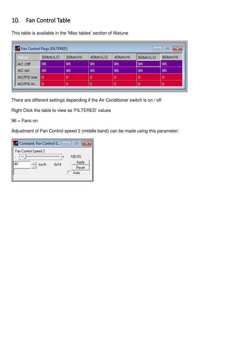
10.10.10.10. Fan Control TableFan Control TableFan Control TableFan Control Table This table is available in the 'Misc tables' section of Nistune
There are different settings depending if the Air Conditioner switch is on / off Right Click the table to view as 'FILTERED' values 96 = Fans on Adjustment of Fan Control speed 2 (middle band) can be made using this parameter:

11.11.11.11. Appendix:Appendix:Appendix:Appendix: ThrThrThrThrottle Enrich ottle Enrich ottle Enrich ottle Enrich indeindeindeindexingxingxingxing The Fuel Throttle Enrich (VE) map is used in addition to the fuel map to trim mixtures based on boost+TPS vs RPM scaling. VE maps are used adjust enrichment based on TPS position for all later model Nissan ECUs. The boost+TPS lookup is peformed with the following table. There has not been any requirement to change these tables. This information is here for completeness only. TPS Voltage Quantifier TPS is calculated firstly by converting TPS raw voltage to a TPS reference position
The TPS reference position is then divided by RPM and used to reference the VE map index table. VE Map Index table Boost sensor available: The value in this table is then multiplied against the boost sensor table Boost sensor not available: Value is divided by two The calculated value is used to index the VE map

VE Map Boost Index table The values in this table are a percentage multiplier against the values in the VE map index table. For example this table is indexed with current boost voltage of 3840mV (3.8V) Take 110 from the previous table x 76.5% = TPS VE index value of 83. So as boost increases the reference to the VE table increases to the right.

12.12.12.12. Appendix:Appendix:Appendix:Appendix: Air conditioning (Air conditioning (Air conditioning (Air conditioning (transplantransplantransplantransplants)ts)ts)ts)
ECU Pin 14 - output to the AC relay (controls AC compressor) Should enable when the ‘Air cond relay’ indicator is displayed in the Nistune software
ECU Pin 57 - Refrigerant pressure sensor
Needs voltage around 3.5V input for the AC to activate. Either use an actual sensor or simulate the sensor input. One customer has used the coolant temp sensor input (pin 56) which operates on a similar voltage to simulate this sensor.
ECU Pin 21 - AC auto amplifier. Switch input to the ECU for AC, wire in to AC switch with transplants where not connected in the current loom. When pins 57 and 51 show valid inputs the Aircond Switch indicator should illuminate in the software, and the Aircond Relay indicator should also illuminate


