45
copyright(c) 1998 W. B. Ligon III 1 Design Automation Requirements RFP Specifications Design CAD Simulation Prototype Production Support Revisions
| Date post: | 27-Dec-2015 |
| Category: |
Documents |
| Upload: | joan-oconnor |
| View: | 215 times |
| Download: | 0 times |
copyright(c) 1998 W. B. Ligon III 1
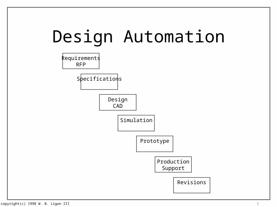
Design AutomationRequirements
RFP
Specifications
DesignCAD
Simulation
Prototype
ProductionSupport
Revisions

copyright(c) 1998 W. B. Ligon III 2
CAD Tools
• Schematic Capture– Graphical design entry– Examples: Cadence, Mentor Graphics
• HDL– Textual description of logic– Permits behavioral description of logic– Examples: VHDL, Verilog

copyright(c) 1998 W. B. Ligon III 3
Design and SimulationDesign
Specification
SchematicCapture
Net List
Simulation
Place andRoute
TimingSimulation
ProductionDrawings
Part Library
logical physicalsymbol, pins
function,delays
layout,pins
electricalcharacteristics

copyright(c) 1998 W. B. Ligon III 4
Schematic Capture
Part A
Part B
Part C
abcde
fghij
uvwxy
U1
U2
U3
AGBI
WF
YJ
• Parts are generic objects with:• symbol• pins• part name (Part A)• instance name (U1)
•Wires connect pins• may be 1 or more bits (bus)• have a signal name• may be implicit (DX)
•Netlist• connected signal names
•U1.a, AG, U3.g•U2.w, WF, U3.f•etc.
• each part instance•U1 is a Part A•U2 is a Part B•U3 is a Part C
DX
DX
z<7..0>
k<7..0>
ZK<7..0>

copyright(c) 1998 W. B. Ligon III 5
Schematic Capture
Part A
Part B
Part C
abcde
fghij
uvwxy
U1
U2
U3
AGBI
WF
YJ
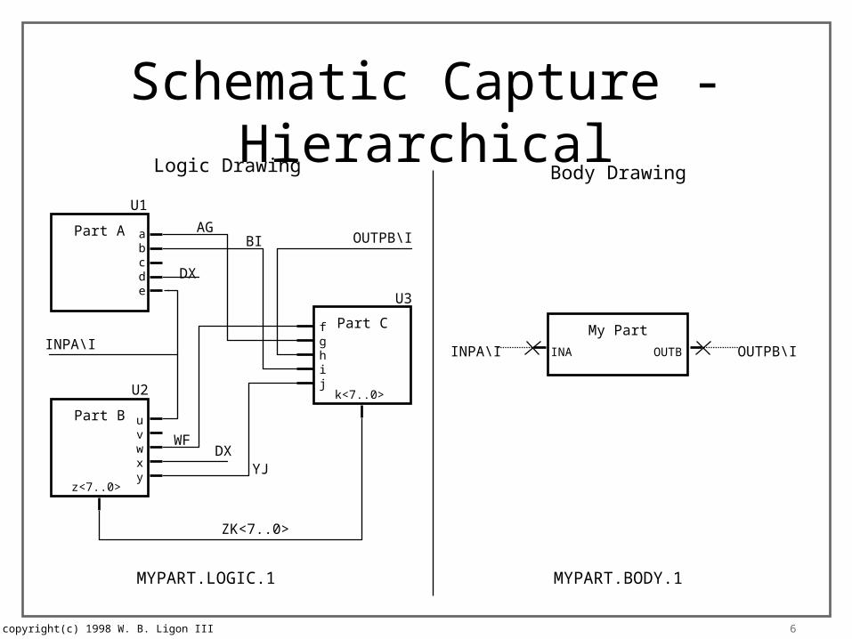
• Part library provides• Part symbol• Location of pins• Part name• Pin names
•Hierarchical tools• Allow user to define parts• Allow design to be subdivided• Support reuse of designs• User must define above info• Later user provides part netlist
•Hierarchical netlists• Look like subroutines• Instance names differentiate multiple instances of a subcircuit
DX
DX
z<7..0>
k<7..0>
ZK<7..0>
copyright(c) 1998 W. B. Ligon III 6
Schematic Capture - Hierarchical
Part A
Part B
Part C
abcde
fghij
uvwxy
U1
U2
U3
AGBI
WF
YJ
DX
DX
z<7..0>
k<7..0>
ZK<7..0>
INPA\I
OUTPB\I
Logic Drawing
INPA\I
Body Drawing
My Part
INA OUTB OUTPB\I
MYPART.LOGIC.1 MYPART.BODY.1

copyright(c) 1998 W. B. Ligon III 7
Netlist Output
• Each tool’s unique format– complex set of translators
• EDIF– early attempt at a standard format– various versions
• HDLs (structural)– Verilog– VHDL (gov’t approved)
copyright(c) 1998 W. B. Ligon III 8
Hardware Definition Languages
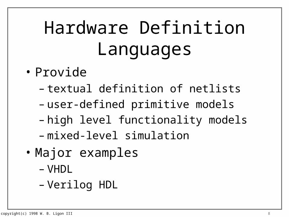
• Provide– textual definition of netlists– user-defined primitive models– high level functionality models– mixed-level simulation
• Major examples– VHDL– Verilog HDL

copyright(c) 1998 W. B. Ligon III 9
Design and SimulationDesign
Specification
Design Entry
Simulation
Synthesis
Place andRoute
TimingSimulation
ProductionDrawings
Part Library
logical physicalsymbol, pins
function,delays
layout,pins
electricalcharacteristics
copyright(c) 1998 W. B. Ligon III 10
HDL Coding Styles
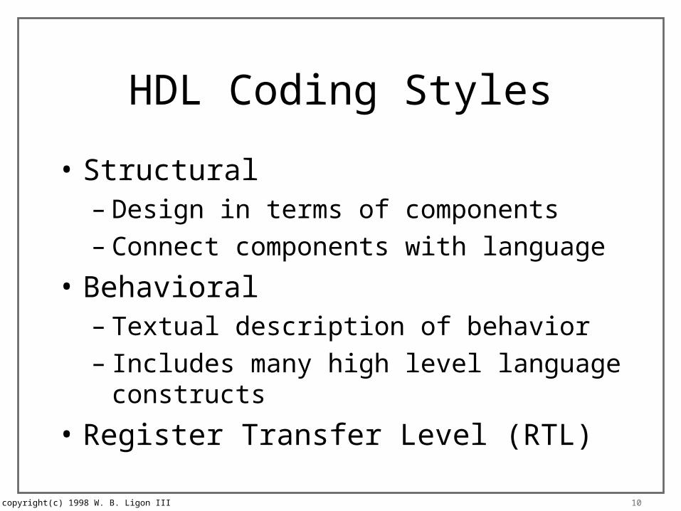
• Structural– Design in terms of components– Connect components with language
• Behavioral– Textual description of behavior– Includes many high level language constructs
• Register Transfer Level (RTL)
copyright(c) 1998 W. B. Ligon III 11
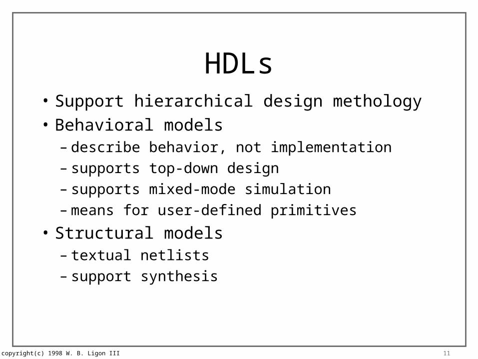
HDLs• Support hierarchical design methology
• Behavioral models– describe behavior, not implementation– supports top-down design– supports mixed-mode simulation– means for user-defined primitives
• Structural models– textual netlists– support synthesis
copyright(c) 1998 W. B. Ligon III 12
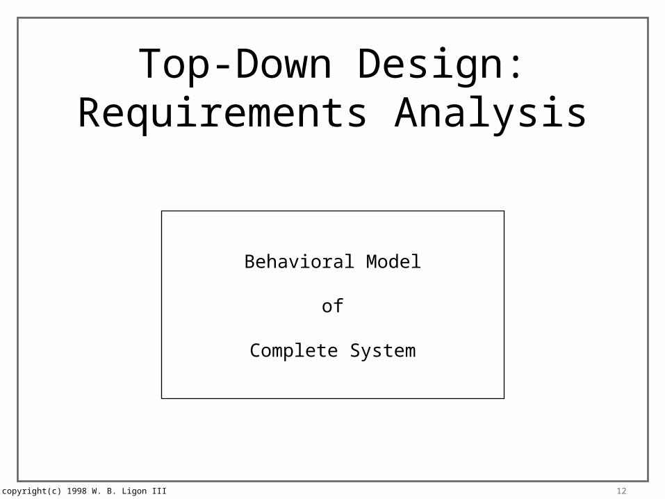
Top-Down Design:Requirements Analysis
Behavioral Model
of
Complete System
copyright(c) 1998 W. B. Ligon III 13
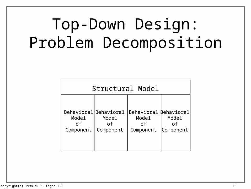
Top-Down Design:Problem Decomposition
Structural Model
BehavioralModel
ofComponent
BehavioralModel
ofComponent
BehavioralModel
ofComponent
BehavioralModel
ofComponent

copyright(c) 1998 W. B. Ligon III 14
Top-Down Design:Problem Decomposition
Structural Model
StructuralModel
StructuralModel
StructuralModel
StructuralModel
Behave
Behave
Behave
Behave
Behave
Behave
Behave
Behave
Behave
Behave
Behave
Behave
copyright(c) 1998 W. B. Ligon III 15
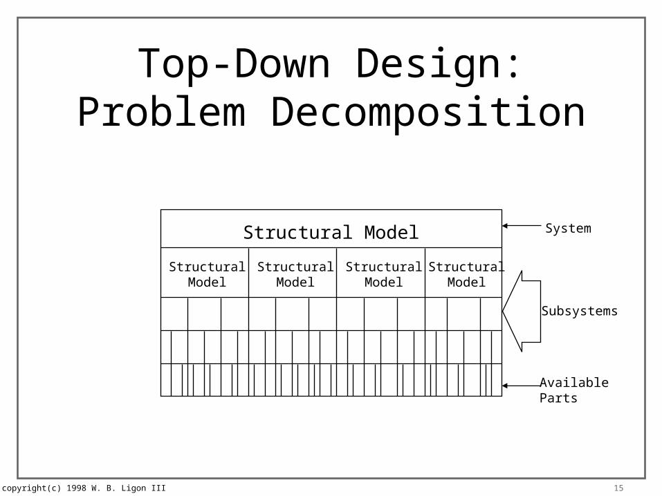
Top-Down Design:Problem Decomposition
Structural Model
StructuralModel
StructuralModel
StructuralModel
StructuralModel
AvailableParts
Subsystems
System

copyright(c) 1998 W. B. Ligon III 16
Top-Down Design:Hybrid Simulation
Structural Model
StructuralModel
StructuralModel
StructuralModel
StructuralModel
BehavioralModel
ofComponent
BehavioralModel
ofComponent
BehavioralModel
ofComponent
Behave
Behave
Unit Under Simulation
copyright(c) 1998 W. B. Ligon III 17
Simulation
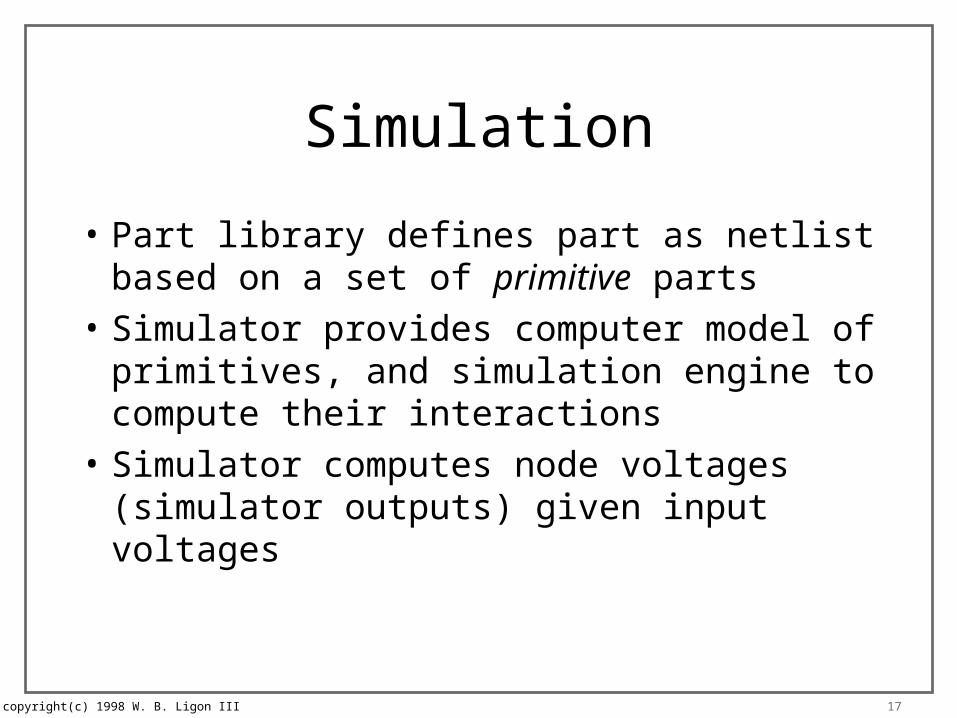
• Part library defines part as netlist based on a set of primitive parts
• Simulator provides computer model of primitives, and simulation engine to compute their interactions
• Simulator computes node voltages (simulator outputs) given input voltages
copyright(c) 1998 W. B. Ligon III 18
Time-Driven Simulation
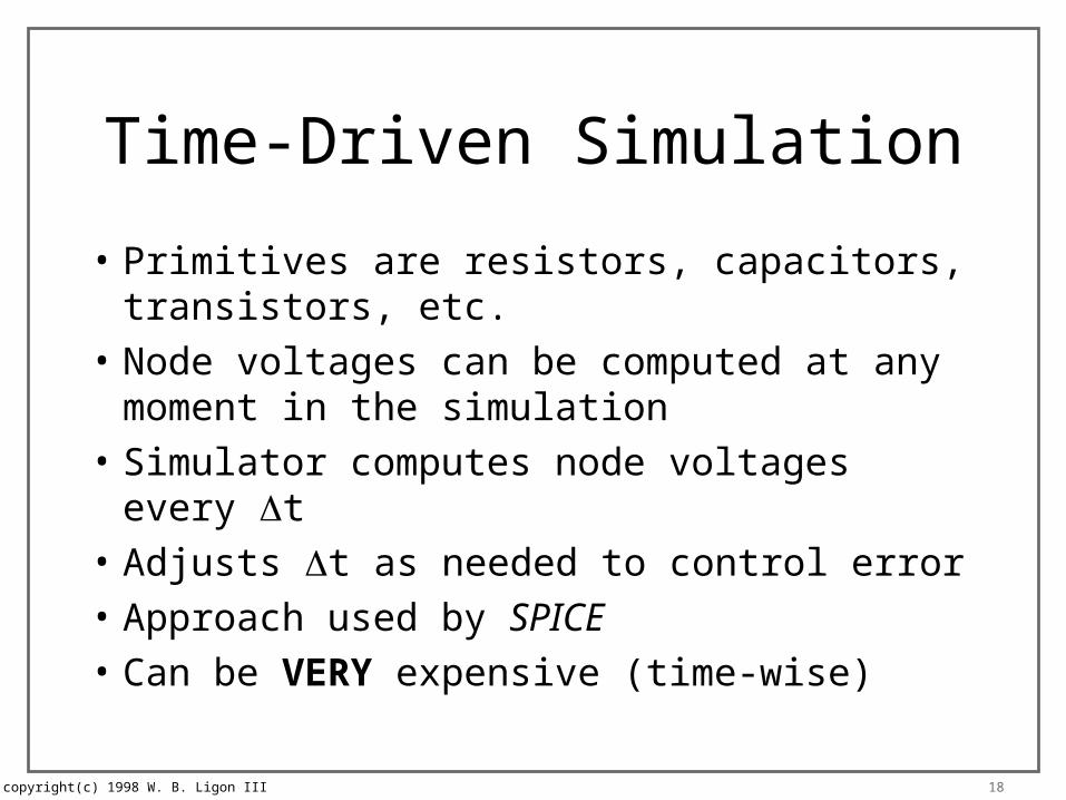
• Primitives are resistors, capacitors, transistors, etc.
• Node voltages can be computed at any moment in the simulation
• Simulator computes node voltages every t
• Adjusts t as needed to control error
• Approach used by SPICE
• Can be VERY expensive (time-wise)
copyright(c) 1998 W. B. Ligon III 19
Event-Driven Simulation
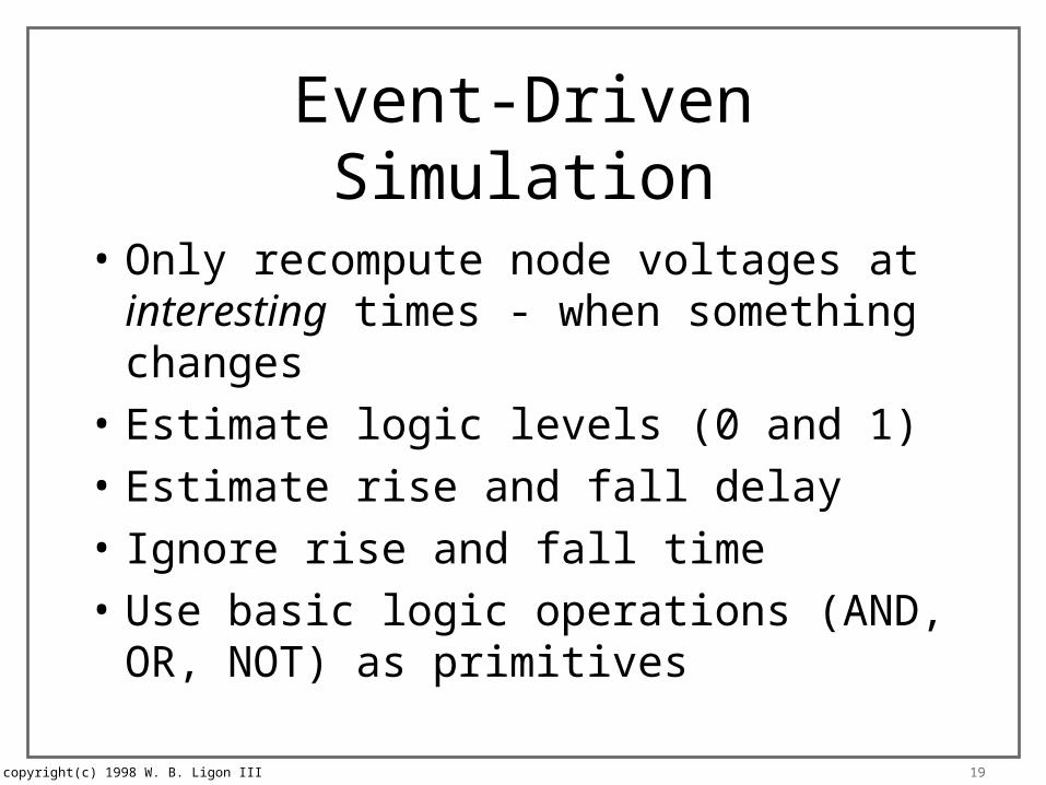
• Only recompute node voltages at interesting times - when something changes
• Estimate logic levels (0 and 1)
• Estimate rise and fall delay
• Ignore rise and fall time
• Use basic logic operations (AND, OR, NOT) as primitives
copyright(c) 1998 W. B. Ligon III 20
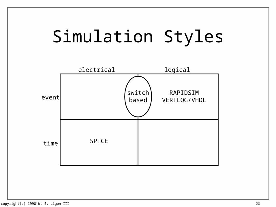
Simulation Styles
electrical logical
event
time
RAPIDSIMVERILOG/VHDL
SPICE
switchbased
copyright(c) 1998 W. B. Ligon III 21
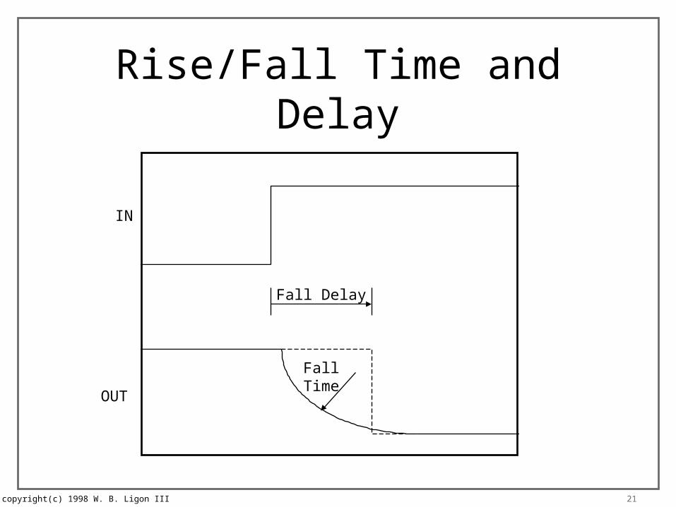
Rise/Fall Time and Delay
IN
OUT
Fall Delay
FallTime

copyright(c) 1998 W. B. Ligon III 22
Event-Driven Simulation
• Simulator keeps sorted list of future events
• Simulator execution– remove next event from list– set sim time to time of the event– simulate the event (primitives)– insert new events (caused by the current event)
into the event list– run until no more events
copyright(c) 1998 W. B. Ligon III 23
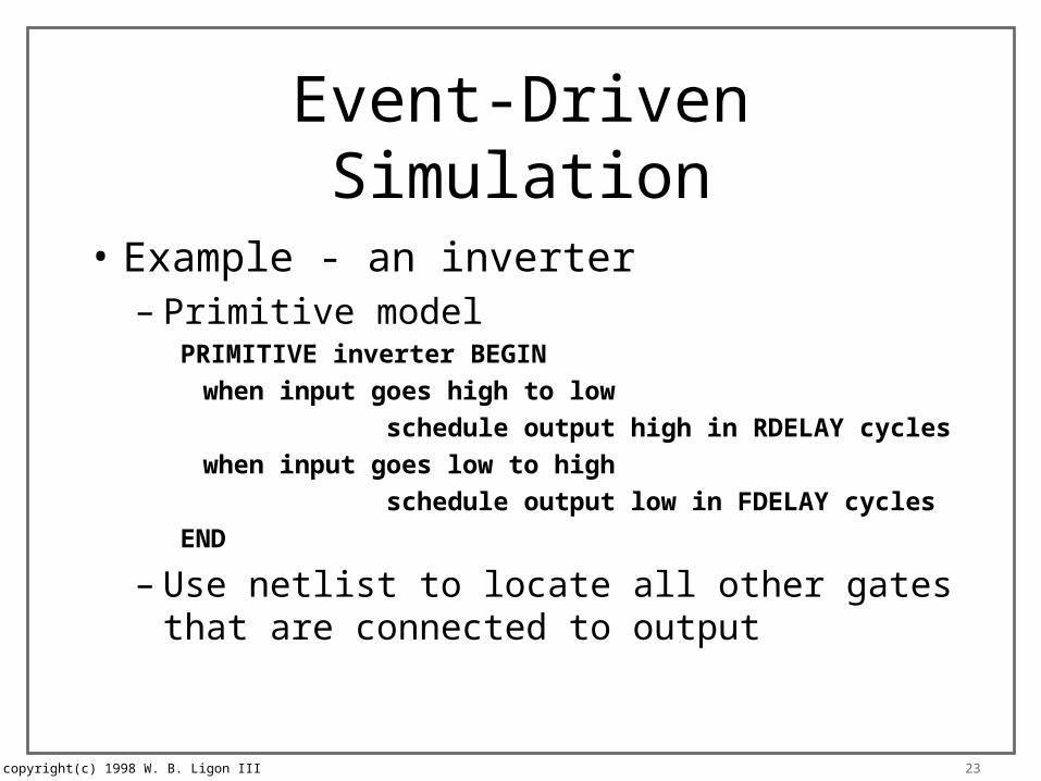
Event-Driven Simulation
• Example - an inverter– Primitive model
PRIMITIVE inverter BEGIN
when input goes high to low
schedule output high in RDELAY cycles
when input goes low to high
schedule output low in FDELAY cycles
END
– Use netlist to locate all other gates that are connected to output
copyright(c) 1998 W. B. Ligon III 24
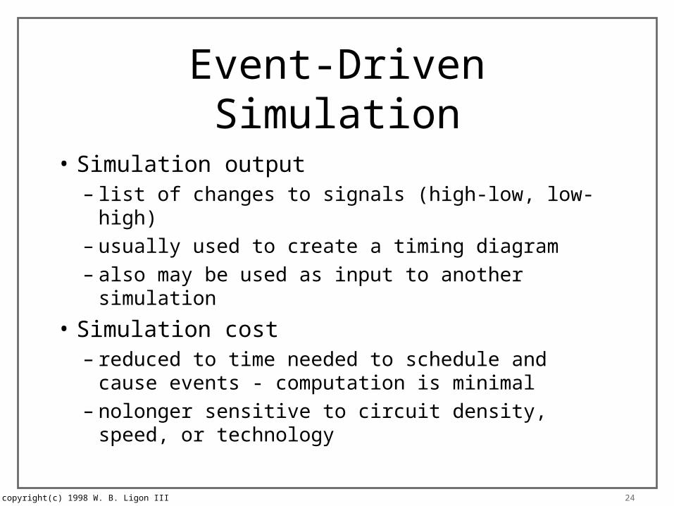
Event-Driven Simulation
• Simulation output– list of changes to signals (high-low, low-high)– usually used to create a timing diagram– also may be used as input to another simulation
• Simulation cost– reduced to time needed to schedule and cause events
- computation is minimal– nolonger sensitive to circuit density, speed, or
technology

copyright(c) 1998 W. B. Ligon III 25
Basic Logic Values
• Each node in one state– 0– 1– U (unknown or undefined)– Z (high impedance)– X (don’t care)
copyright(c) 1998 W. B. Ligon III 26
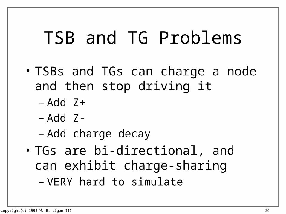
TSB and TG Problems
• TSBs and TGs can charge a node and then stop driving it– Add Z+– Add Z-– Add charge decay
• TGs are bi-directional, and can exhibit charge-sharing– VERY hard to simulate
copyright(c) 1998 W. B. Ligon III 27
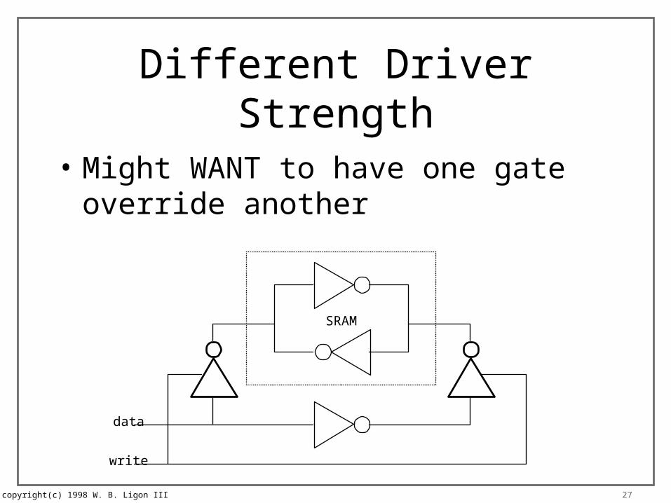
Different Driver Strength
• Might WANT to have one gate override another
data
write
SRAM

copyright(c) 1998 W. B. Ligon III 28
Dealing with OC OutputsVdd
A
B
C
F
Wire-ANDconfiguration
F = A’B’C’
copyright(c) 1998 W. B. Ligon III 29
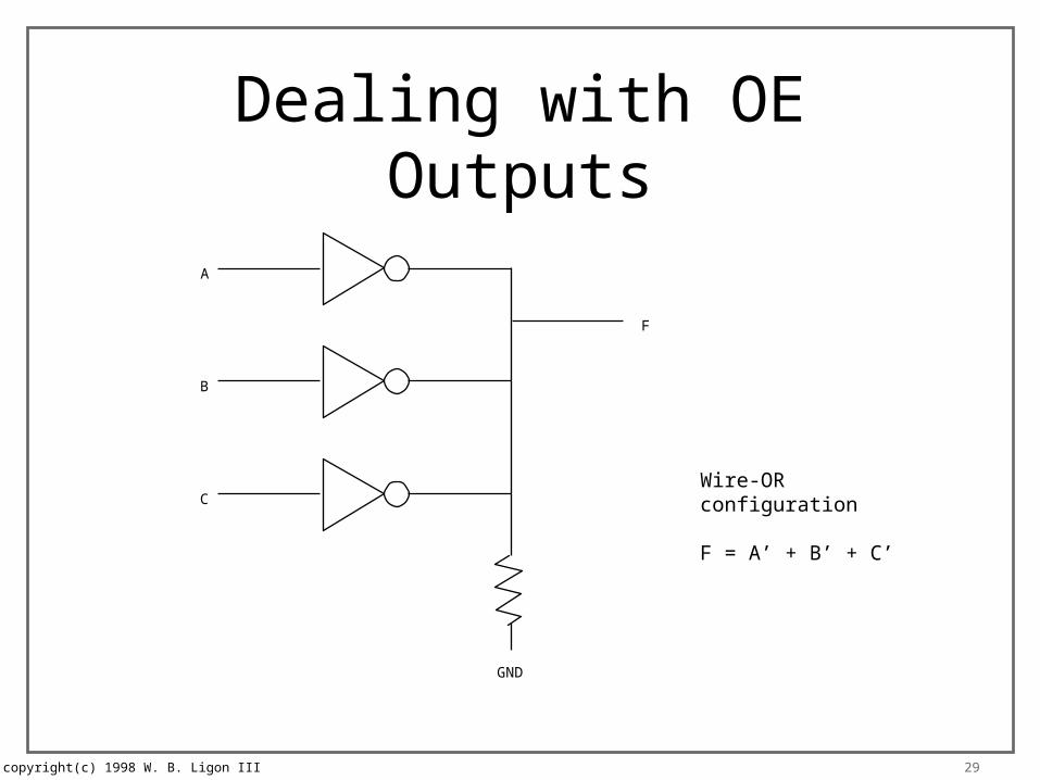
Dealing with OE Outputs
GND
A
B
C
F
Wire-ORconfiguration
F = A’ + B’ + C’
copyright(c) 1998 W. B. Ligon III 30
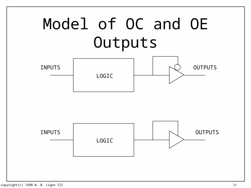
Model of OC and OE Outputs
INPUTS OUTPUTS
LOGIC
INPUTS OUTPUTS
LOGIC
copyright(c) 1998 W. B. Ligon III 31
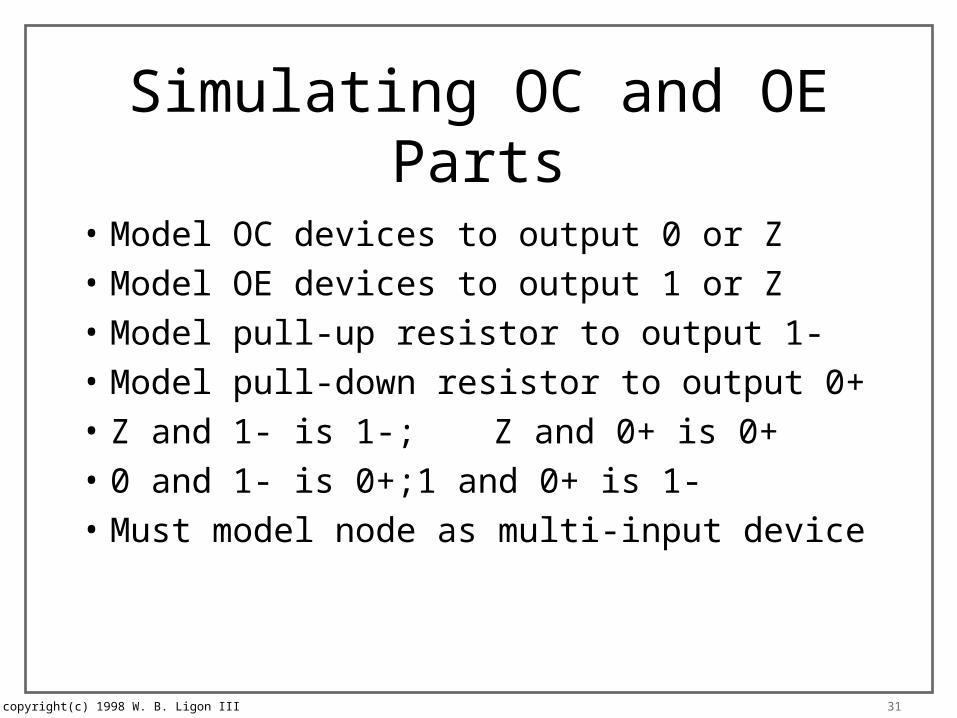
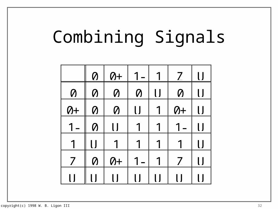
Simulating OC and OE Parts
• Model OC devices to output 0 or Z
• Model OE devices to output 1 or Z
• Model pull-up resistor to output 1-
• Model pull-down resistor to output 0+
• Z and 1- is 1-; Z and 0+ is 0+
• 0 and 1- is 0+; 1 and 0+ is 1-
• Must model node as multi-input device
copyright(c) 1998 W. B. Ligon III 32
Combining Signals
0 0+ 1- 1 Z U0 0 0 0 U 0 U
0+ 0 0 U 1 0+ U1- 0 U 1 1 1- U1 U 1 1 1 1 UZ 0 0+ 1- 1 Z UU U U U U U U
copyright(c) 1998 W. B. Ligon III 33
Advanced Logic Simulators
• Can operate at switch or gate level
• Node Model– logic level– level strength– path strength
• Switch simulations model for both 0 and 1
• Table driven engine evalutes node states
copyright(c) 1998 W. B. Ligon III 34
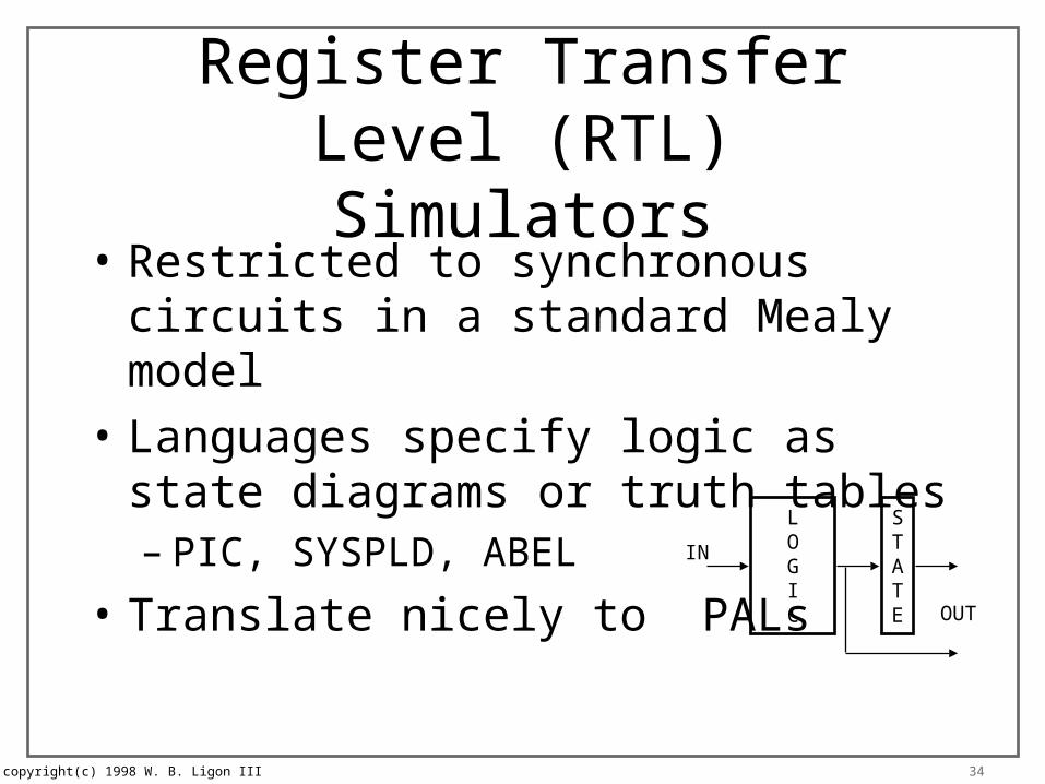
Register Transfer Level (RTL)Simulators
• Restricted to synchronous circuits in a standard Mealy model
• Languages specify logic as state diagrams or truth tables– PIC, SYSPLD, ABEL
• Translate nicely to PALsSTATE
LOGIC
IN
OUT
copyright(c) 1998 W. B. Ligon III 35
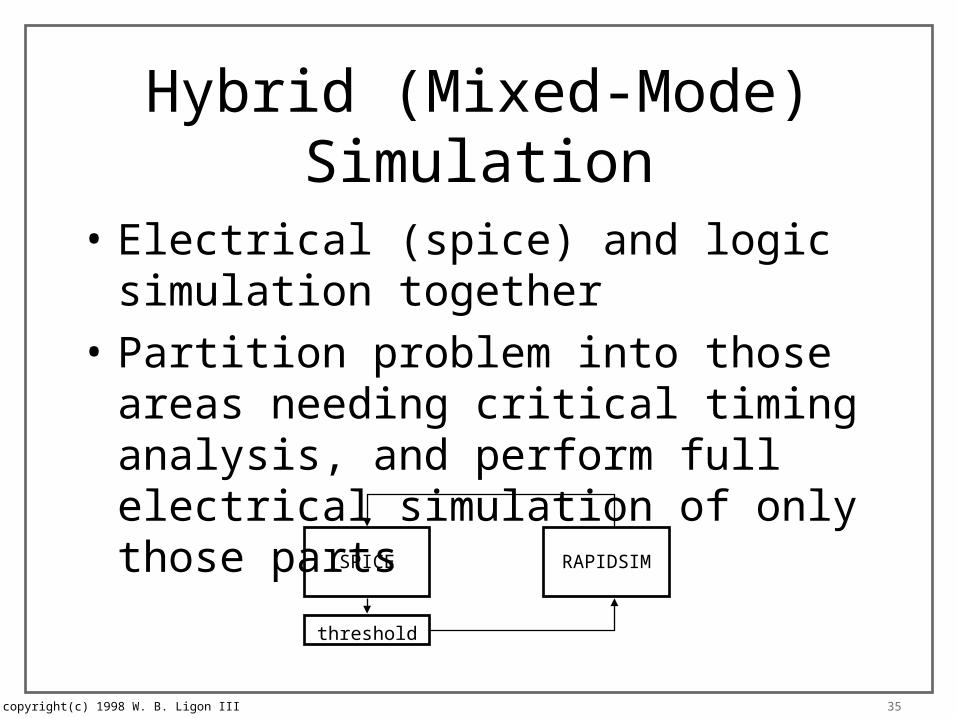
Hybrid (Mixed-Mode) Simulation
• Electrical (spice) and logic simulation together
• Partition problem into those areas needing critical timing analysis, and perform full electrical simulation of only those parts
SPICE RAPIDSIM
threshold
copyright(c) 1998 W. B. Ligon III 36
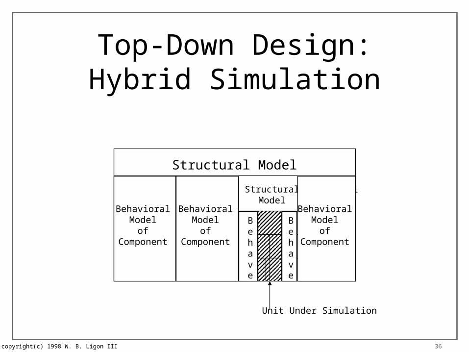
Top-Down Design:Hybrid Simulation
Structural Model
StructuralModel
StructuralModel
StructuralModel
StructuralModel
BehavioralModel
ofComponent
BehavioralModel
ofComponent
BehavioralModel
ofComponent
Behave
Behave
Unit Under Simulation
copyright(c) 1998 W. B. Ligon III 37
Simulation Models
• Inputs to simulator– netlist– stimulus– device models
• Models composed of– primitive logic functions– timing

copyright(c) 1998 W. B. Ligon III 38
Simulation Models
• Primitive logic functions– AND, OR, NOT, NAND, NOR, XOR– TSB, TG, pull-up, etc.– no-delay
• Timing– rise time: best, worst, typical– fall time: best, worst, typical– setup time, hold time, pulse width

copyright(c) 1998 W. B. Ligon III 39
Typical FF Model• Behavior
– primitive, no-delay gates, or HDL model
• Timing– rise/fall delay from clock to Q
– setup time, hold time
– clock minimum high/low pulse width
– preset/reset delay to Q
– min preset/reset pulse width
– min preset/reset to clock spacing
copyright(c) 1998 W. B. Ligon III 40
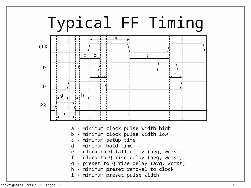
Typical FF TimingCLK
D
Q
PR
a
bc d
e f
g h
i
a - minimum clock pulse width highb - minimum clock pulse width lowc - minimum setup timed - minimum hold timee - clock to Q fall delay (avg, worst)f - clock to Q rise delay (avg, worst)g - preset to Q rise delay (avg, worst)h - minimum preset removal to clocki - minimum preset pulse width

copyright(c) 1998 W. B. Ligon III 41
Routing
• Router inputs– netlist from schematic capture– physical part data from part library
• physical dimension
• pin data– placement, size
– mount type
– electrical characteristics
– technology and user settings
copyright(c) 1998 W. B. Ligon III 42
Routing - Inputs
• Netlist– table of part numbers and type– connection list by part and pin number
• Pin data– signal name– special flags– position, size– resistance and capacitance
copyright(c) 1998 W. B. Ligon III 43
Routing - Parameters
• Router settings– dimensions of layout space– placement of connectors, some parts– routing layers, spacing, interconnects– electrical characteristics (resistance,
capacitance)– routing goals (trace length, power density, etc.)
copyright(c) 1998 W. B. Ligon III 44
Routing - Outputs
• Layout– part placement– interconnect– power distribution
• Information– errors– routing density– routing data by net in netlist - feed back to simulator
copyright(c) 1998 W. B. Ligon III 45
Back Annotation
• Output data from router added to schematic
• Simulations to estimate timing– identify critical paths– full logical simulation– full electrical simulation
• Leads to re-routing, or re-design


