93
INSTRUCTION MANUAL MAGNETIC FLOWMETERS 50SM1000 Design Levels C & D MICROPROCESSOR-BASED SIGNAL CONVERTER PN25040

INSTRUCTION MANUALMAGNETIC FLOWMETERS50SM1000 Design Levels C & D
MICROPROCESSOR-BASED SIGNAL CONVERTER
PN25040

The following are trademarks of ABB Inc:CHAMELEON®
MAG-X®
MICRO-DCISUPERVISORSUPERVISOR-PC
The following is a registered trademark of Microsoft:MS-DOS®
The following is a registered trademark of the HART Communication Foundation: HART®
WARNING notices as used in this manual apply to hazards or unsafe practices which could result in personal in-jury or death.
CAUTION notices apply to hazards or unsafe practices which could result in property damage.
NOTES highlight procedures and contain information which assist the operator in understanding the informationcontained in this manual.
All software, including design, appearance, algorithms and source codes, is owned and copyrighted byABB Inc. or its suppliers.
WARNING POSSIBLE PROCESS UPSETSMaintenance must be performed only by qualified personnel and only after securing equipmentcontrolled by this product. Adjusting or removing this product while it is in the system may upset theprocess being controlled. Some process upsets may cause injury or damage.
NOTICE
The information contained in this document is subject to change without notice. ABB Inc. reserves theright to make minor changes to this publication, such as company name & logos as well as other minorcorrections, without necessarily changing the publication number.
ABB Inc., its affiliates, employees, and agents, and the authors of and contributors to this publicationspecifically disclaim all liabilities and warranties, express and implied (including warranties ofmerchantability and fitness for a particular purpose), for the accuracy, currency, completeness, and/orreliability of the information contained herein and/or for the fitness for any particular use and/or for theperformance of any material and/or equipment selected in whole or part with the user of/or in relianceupon information contained herein. Selection of materials and/or equipment is at the sole risk of theuser of this publication.
This document contains proprietary information of ABB Inc. and is issued in strict confidence. Its use,or reproduction for use, for the reverse engineering, development or manufacture of hardware orsoftware described herein is prohibited. No part of this document may be photocopied or reproducedwithout the prior written consent of ABB Inc.
Copyright 2002 ABB Inc. [July, 2002]

Table of Contents
READ FIRST . . . . . . . . . . . . . . . . . . . . . . . . . . . . . . . . . . . . . . . . . . . . . . . . . . . . . . . . . . . I
1.0 INTRODUCTION . . . . . . . . . . . . . . . . . . . . . . . . . . . . . . . . . . . . . . . . . . . . . . . . . . 1-11.1 General Description . . . . . . . . . . . . . . . . . . . . . . . . . . . . . . . . . . . . . . . . . . . . . . . . . . . . . . . . . . . . . . 1-1
1.2 Model Number Breakdown . . . . . . . . . . . . . . . . . . . . . . . . . . . . . . . . . . . . . . . . . . . . . . . . . . . . . . . . . 1-4
1.3 Firmware Menu Sequence . . . . . . . . . . . . . . . . . . . . . . . . . . . . . . . . . . . . . . . . . . . . . . . . . . . . . . . . . 1-6
1.4 Specifications . . . . . . . . . . . . . . . . . . . . . . . . . . . . . . . . . . . . . . . . . . . . . . . . . . . . . . . . . . . . . . . . . . . 1-8
2.0 INSTALLATION . . . . . . . . . . . . . . . . . . . . . . . . . . . . . . . . . . . . . . . . . . . . . . . . . . . 2-12.1 Inspection . . . . . . . . . . . . . . . . . . . . . . . . . . . . . . . . . . . . . . . . . . . . . . . . . . . . . . . . . . . . . . . . . . . . . . 2-1
2.2 Location and Mounting . . . . . . . . . . . . . . . . . . . . . . . . . . . . . . . . . . . . . . . . . . . . . . . . . . . . . . . . . . . . 2-1
2.3 Electrical Interconnections . . . . . . . . . . . . . . . . . . . . . . . . . . . . . . . . . . . . . . . . . . . . . . . . . . . . . . . . . 2-32.3.1 Remotely Mounted Signal Converter . . . . . . . . . . . . . . . . . . . . . . . . . . . . . . . . . . . . . . . . . . . . 2-3
3.0 START-UP AND OPERATION . . . . . . . . . . . . . . . . . . . . . . . . . . . . . . . . . . . . . . . 3-13.1 Start-Up . . . . . . . . . . . . . . . . . . . . . . . . . . . . . . . . . . . . . . . . . . . . . . . . . . . . . . . . . . . . . . . . . . . . . . . 3-1
3.1.1 Calibration Data. . . . . . . . . . . . . . . . . . . . . . . . . . . . . . . . . . . . . . . . . . . . . . . . . . . . . . . . . . . . . 3-1
3.1.2 Flow Measurement . . . . . . . . . . . . . . . . . . . . . . . . . . . . . . . . . . . . . . . . . . . . . . . . . . . . . . . . . . 3-2
3.2 Configuration Procedure. . . . . . . . . . . . . . . . . . . . . . . . . . . . . . . . . . . . . . . . . . . . . . . . . . . . . . . . . . . 3-33.2.1 Keypad Functions . . . . . . . . . . . . . . . . . . . . . . . . . . . . . . . . . . . . . . . . . . . . . . . . . . . . . . . . . . . 3-4
3.2.1.1 Adjustments and Indicators . . . . . . . . . . . . . . . . . . . . . . . . . . . . . . . . . . . . . . . . . . . . . . 3-43.2.1.2 Key Descriptions . . . . . . . . . . . . . . . . . . . . . . . . . . . . . . . . . . . . . . . . . . . . . . . . . . . . . . 3-5
3.3 Changing Parameters . . . . . . . . . . . . . . . . . . . . . . . . . . . . . . . . . . . . . . . . . . . . . . . . . . . . . . . . . . . . . 3-73.3.1 Program Protection . . . . . . . . . . . . . . . . . . . . . . . . . . . . . . . . . . . . . . . . . . . . . . . . . . . . . . . . . . 3-7
3.3.2 Program Protection Code . . . . . . . . . . . . . . . . . . . . . . . . . . . . . . . . . . . . . . . . . . . . . . . . . . . . . 3-8
3.3.3 Language . . . . . . . . . . . . . . . . . . . . . . . . . . . . . . . . . . . . . . . . . . . . . . . . . . . . . . . . . . . . . . . . . 3-8
3.3.4 Submenu Primary . . . . . . . . . . . . . . . . . . . . . . . . . . . . . . . . . . . . . . . . . . . . . . . . . . . . . . . . . . . 3-8
3.3.5 Cal Factor/Meter Capacity. . . . . . . . . . . . . . . . . . . . . . . . . . . . . . . . . . . . . . . . . . . . . . . . . . . . . 3-9
3.3.6 Range . . . . . . . . . . . . . . . . . . . . . . . . . . . . . . . . . . . . . . . . . . . . . . . . . . . . . . . . . . . . . . . . . . . 3-10
3.3.7 Pulse Factor . . . . . . . . . . . . . . . . . . . . . . . . . . . . . . . . . . . . . . . . . . . . . . . . . . . . . . . . . . . . . . 3-113.3.7.1 Allowable Pulse Factors . . . . . . . . . . . . . . . . . . . . . . . . . . . . . . . . . . . . . . . . . . . . . . . 3-113.3.7.2 Pulse Factor Summary . . . . . . . . . . . . . . . . . . . . . . . . . . . . . . . . . . . . . . . . . . . . . . . . 3-12
3.3.8 Pulse Width . . . . . . . . . . . . . . . . . . . . . . . . . . . . . . . . . . . . . . . . . . . . . . . . . . . . . . . . . . . . . . . 3-13
3.3.9 Low Flow Cut-Off. . . . . . . . . . . . . . . . . . . . . . . . . . . . . . . . . . . . . . . . . . . . . . . . . . . . . . . . . . . 3-13
3.3.10 Damping . . . . . . . . . . . . . . . . . . . . . . . . . . . . . . . . . . . . . . . . . . . . . . . . . . . . . . . . . . . . . . . . 3-13
3.3.11 Filter. . . . . . . . . . . . . . . . . . . . . . . . . . . . . . . . . . . . . . . . . . . . . . . . . . . . . . . . . . . . . . . . . . . . 3-13
3.3.12 Density . . . . . . . . . . . . . . . . . . . . . . . . . . . . . . . . . . . . . . . . . . . . . . . . . . . . . . . . . . . . . . . . . 3-14
3.3.13 System Zero Adjust . . . . . . . . . . . . . . . . . . . . . . . . . . . . . . . . . . . . . . . . . . . . . . . . . . . . . . . . 3-14
3.3.14 Submenu Unit . . . . . . . . . . . . . . . . . . . . . . . . . . . . . . . . . . . . . . . . . . . . . . . . . . . . . . . . . . . . 3-153.3.14.1 Range Unit . . . . . . . . . . . . . . . . . . . . . . . . . . . . . . . . . . . . . . . . . . . . . . . . . . . . . . . . 3-153.3.14.2 Totalizer Unit . . . . . . . . . . . . . . . . . . . . . . . . . . . . . . . . . . . . . . . . . . . . . . . . . . . . . . . 3-153.3.14.3 Unit Factor. . . . . . . . . . . . . . . . . . . . . . . . . . . . . . . . . . . . . . . . . . . . . . . . . . . . . . . . . 3-173.3.14.4 Unit Name . . . . . . . . . . . . . . . . . . . . . . . . . . . . . . . . . . . . . . . . . . . . . . . . . . . . . . . . . 3-17
50SM1000 SIGNAL CONVERTER INSTRUCTION MANUAL
i

3.3.15 Submenu Alarm . . . . . . . . . . . . . . . . . . . . . . . . . . . . . . . . . . . . . . . . . . . . . . . . . . . . . . . . . . 3-173.3.15.1 Error Register . . . . . . . . . . . . . . . . . . . . . . . . . . . . . . . . . . . . . . . . . . . . . . . . . . . . . . 3-173.3.15.2 Error Messages . . . . . . . . . . . . . . . . . . . . . . . . . . . . . . . . . . . . . . . . . . . . . . . . . . . . 3-183.3.13.3 Max Alarm . . . . . . . . . . . . . . . . . . . . . . . . . . . . . . . . . . . . . . . . . . . . . . . . . . . . . . . . 3-193.3.15.4 Min Alarm . . . . . . . . . . . . . . . . . . . . . . . . . . . . . . . . . . . . . . . . . . . . . . . . . . . . . . . . . 3-19
3.3.16 Submenu-Current output . . . . . . . . . . . . . . . . . . . . . . . . . . . . . . . . . . . . . . . . . . . . . . . . . . . 3-19
3.3.17 Submenu-Data link. . . . . . . . . . . . . . . . . . . . . . . . . . . . . . . . . . . . . . . . . . . . . . . . . . . . . . . . 3-20
3.3.18 Submenu Function Test . . . . . . . . . . . . . . . . . . . . . . . . . . . . . . . . . . . . . . . . . . . . . . . . . . . . 3-21
3.3.19 Submenu-Detector e. pipe . . . . . . . . . . . . . . . . . . . . . . . . . . . . . . . . . . . . . . . . . . . . . . . . . . 3-25
3.3.20 Submenu Totalizer . . . . . . . . . . . . . . . . . . . . . . . . . . . . . . . . . . . . . . . . . . . . . . . . . . . . . . . . 3-27
3.3.21 Submenu Display . . . . . . . . . . . . . . . . . . . . . . . . . . . . . . . . . . . . . . . . . . . . . . . . . . . . . . . . . 3-28
3.3.22 Submenu Operating Mode . . . . . . . . . . . . . . . . . . . . . . . . . . . . . . . . . . . . . . . . . . . . . . . . . . 3-303.3.22.1 Operating mode . . . . . . . . . . . . . . . . . . . . . . . . . . . . . . . . . . . . . . . . . . . . . . . . . . . . 3-30
3.3.22.1.1 Standard . . . . . . . . . . . . . . . . . . . . . . . . . . . . . . . . . . . . . . . . . . . . . . . . . 3-303.3.22.1.2 Piston Pumps (Pulsating Flow) . . . . . . . . . . . . . . . . . . . . . . . . . . . . . . . . 3-30
3.3.22.2 Flow Direction . . . . . . . . . . . . . . . . . . . . . . . . . . . . . . . . . . . . . . . . . . . . . . . . . . . . . 3-303.3.22.3 Flow Direction Display . . . . . . . . . . . . . . . . . . . . . . . . . . . . . . . . . . . . . . . . . . . . . . . 3-30
3.3.23 Load and Store Configuration Data from the External EEPROM. . . . . . . . . . . . . . . . . . . . . 3-303.3.23.1 Load Data from the External EEPROM . . . . . . . . . . . . . . . . . . . . . . . . . . . . . . . . . . 3-313.3.23.2 Store Data in the External EEPROM . . . . . . . . . . . . . . . . . . . . . . . . . . . . . . . . . . . . 3-31
3.3.24 Software Level . . . . . . . . . . . . . . . . . . . . . . . . . . . . . . . . . . . . . . . . . . . . . . . . . . . . . . . . . . . 3-31
3.3.25 TAG Number. . . . . . . . . . . . . . . . . . . . . . . . . . . . . . . . . . . . . . . . . . . . . . . . . . . . . . . . . . . . . 3-31
3.3.26 Code number . . . . . . . . . . . . . . . . . . . . . . . . . . . . . . . . . . . . . . . . . . . . . . . . . . . . . . . . . . . . 3-31
4.0 FUNCTIONAL DESCRIPTION. . . . . . . . . . . . . . . . . . . . . . . . . . . . . . . . . . . . . . . . 4-14.1 Basic Functions . . . . . . . . . . . . . . . . . . . . . . . . . . . . . . . . . . . . . . . . . . . . . . . . . . . . . . . . . . . . . . . . . 4-1
4.2 Design Features. . . . . . . . . . . . . . . . . . . . . . . . . . . . . . . . . . . . . . . . . . . . . . . . . . . . . . . . . . . . . . . . . 4-14.2.1 Micro-processor Controlled . . . . . . . . . . . . . . . . . . . . . . . . . . . . . . . . . . . . . . . . . . . . . . . . . . . 4-1
4.2.2 Display . . . . . . . . . . . . . . . . . . . . . . . . . . . . . . . . . . . . . . . . . . . . . . . . . . . . . . . . . . . . . . . . . . . 4-1
4.2.3 Rangeability . . . . . . . . . . . . . . . . . . . . . . . . . . . . . . . . . . . . . . . . . . . . . . . . . . . . . . . . . . . . . . . 4-1
4.2.4 Bi-Directional Flow . . . . . . . . . . . . . . . . . . . . . . . . . . . . . . . . . . . . . . . . . . . . . . . . . . . . . . . . . . 4-1
4.2.5 Flow Direction. . . . . . . . . . . . . . . . . . . . . . . . . . . . . . . . . . . . . . . . . . . . . . . . . . . . . . . . . . . . . . 4-2
4.2.6 Output Signals . . . . . . . . . . . . . . . . . . . . . . . . . . . . . . . . . . . . . . . . . . . . . . . . . . . . . . . . . . . . . 4-24.2.6.1 Analog Output . . . . . . . . . . . . . . . . . . . . . . . . . . . . . . . . . . . . . . . . . . . . . . . . . . . . . . . 4-24.2.6.2 Optional Outputs . . . . . . . . . . . . . . . . . . . . . . . . . . . . . . . . . . . . . . . . . . . . . . . . . . . . . 4-24.2.6.3 Scaled Pulse . . . . . . . . . . . . . . . . . . . . . . . . . . . . . . . . . . . . . . . . . . . . . . . . . . . . . . . . 4-2
4.2.7 Data Link . . . . . . . . . . . . . . . . . . . . . . . . . . . . . . . . . . . . . . . . . . . . . . . . . . . . . . . . . . . . . . . . . 4-24.2.7.1 ASCII . . . . . . . . . . . . . . . . . . . . . . . . . . . . . . . . . . . . . . . . . . . . . . . . . . . . . . . . . . . . . . 4-34.2.7.2 MICRO-DCI Binary. . . . . . . . . . . . . . . . . . . . . . . . . . . . . . . . . . . . . . . . . . . . . . . . . . . . 4-3
4.2.8 HART Interface. . . . . . . . . . . . . . . . . . . . . . . . . . . . . . . . . . . . . . . . . . . . . . . . . . . . . . . . . . . . . 4-34.2.8.1 HART Firmware Menu Sequence . . . . . . . . . . . . . . . . . . . . . . . . . . . . . . . . . . . . . . . . 4-4
4.2.9 Optional Features on Base Board . . . . . . . . . . . . . . . . . . . . . . . . . . . . . . . . . . . . . . . . . . . . . . 4-4
4.2.10 Reference Voltage and Impedance . . . . . . . . . . . . . . . . . . . . . . . . . . . . . . . . . . . . . . . . . . . . 4-4
4.2.11 Power . . . . . . . . . . . . . . . . . . . . . . . . . . . . . . . . . . . . . . . . . . . . . . . . . . . . . . . . . . . . . . . . . . . 4-5
50SM1000 SIGNAL CONVERTER INSTRUCTION MANUAL
ii

5.0 CALIBRATION . . . . . . . . . . . . . . . . . . . . . . . . . . . . . . . . . . . . . . . . . . . . . . . . . . . 5-15.1 General Discussion. . . . . . . . . . . . . . . . . . . . . . . . . . . . . . . . . . . . . . . . . . . . . . . . . . . . . . . . . . . . . . . 5-1
5.2 Test Requirements . . . . . . . . . . . . . . . . . . . . . . . . . . . . . . . . . . . . . . . . . . . . . . . . . . . . . . . . . . . . . . . 5-25.2.1 Equipment . . . . . . . . . . . . . . . . . . . . . . . . . . . . . . . . . . . . . . . . . . . . . . . . . . . . . . . . . . . . . . . . . 5-25.2.2 Signal Simulator . . . . . . . . . . . . . . . . . . . . . . . . . . . . . . . . . . . . . . . . . . . . . . . . . . . . . . . . . . . . 5-2
5.2.2.1 55XC2000 Simulator . . . . . . . . . . . . . . . . . . . . . . . . . . . . . . . . . . . . . . . . . . . . . . . . . . . 5-25.2.2.2 55XC4000 Simulator . . . . . . . . . . . . . . . . . . . . . . . . . . . . . . . . . . . . . . . . . . . . . . . . . . . 5-4
5.2.3 Signal Converter Disassembly . . . . . . . . . . . . . . . . . . . . . . . . . . . . . . . . . . . . . . . . . . . . . . . . . 5-55.2.3.1 Removing the Signal Converter from the base . . . . . . . . . . . . . . . . . . . . . . . . . . . . . . . 5-55.2.3.2 Disassembly of the Signal Converter . . . . . . . . . . . . . . . . . . . . . . . . . . . . . . . . . . . . . . 5-5
5.3 Performance Verification. . . . . . . . . . . . . . . . . . . . . . . . . . . . . . . . . . . . . . . . . . . . . . . . . . . . . . . . . . . 5-6
5.4 Initialization . . . . . . . . . . . . . . . . . . . . . . . . . . . . . . . . . . . . . . . . . . . . . . . . . . . . . . . . . . . . . . . . . . . . . 5-8
5.5 Calibration Procedure . . . . . . . . . . . . . . . . . . . . . . . . . . . . . . . . . . . . . . . . . . . . . . . . . . . . . . . . . . . . . 5-85.5.1 Code Number . . . . . . . . . . . . . . . . . . . . . . . . . . . . . . . . . . . . . . . . . . . . . . . . . . . . . . . . . . . . . . 5-9
5.5.2 Options . . . . . . . . . . . . . . . . . . . . . . . . . . . . . . . . . . . . . . . . . . . . . . . . . . . . . . . . . . . . . . . . . . . 5-9
5.5.3 Submenu Instr. Adjust . . . . . . . . . . . . . . . . . . . . . . . . . . . . . . . . . . . . . . . . . . . . . . . . . . . . . . . 5-105.5.3.1 Forward Flow Instrument Adjust. . . . . . . . . . . . . . . . . . . . . . . . . . . . . . . . . . . . . . . . . 5-105.5.3.2 Reverse Flow Instrument Adjust . . . . . . . . . . . . . . . . . . . . . . . . . . . . . . . . . . . . . . . . . 5-105.5.3.3 Zero Adjust . . . . . . . . . . . . . . . . . . . . . . . . . . . . . . . . . . . . . . . . . . . . . . . . . . . . . . . . . 5-115.5.3.4 Calibration (Bailey-Fischer & Porter use only) . . . . . . . . . . . . . . . . . . . . . . . . . . . . . . 5-115.5.3.5 Adjust Iout 20mA . . . . . . . . . . . . . . . . . . . . . . . . . . . . . . . . . . . . . . . . . . . . . . . . . . . . . 5-115.5.3.6 Adjust Iout 4mA . . . . . . . . . . . . . . . . . . . . . . . . . . . . . . . . . . . . . . . . . . . . . . . . . . . . . . 5-125.5.3.7 Adjustment of Integrators . . . . . . . . . . . . . . . . . . . . . . . . . . . . . . . . . . . . . . . . . . . . . . 5-12
5.5.4 Excitation. . . . . . . . . . . . . . . . . . . . . . . . . . . . . . . . . . . . . . . . . . . . . . . . . . . . . . . . . . . . . . . . . 5-12
5.5.5 Maximum Velocity . . . . . . . . . . . . . . . . . . . . . . . . . . . . . . . . . . . . . . . . . . . . . . . . . . . . . . . . . . 5-12
5.5.6 Cal-Factor . . . . . . . . . . . . . . . . . . . . . . . . . . . . . . . . . . . . . . . . . . . . . . . . . . . . . . . . . . . . . . . . 5-13
5.5.7 Range < .05 Range DN. . . . . . . . . . . . . . . . . . . . . . . . . . . . . . . . . . . . . . . . . . . . . . . . . . . . . . 5-13
5.5.8 Keypad Old . . . . . . . . . . . . . . . . . . . . . . . . . . . . . . . . . . . . . . . . . . . . . . . . . . . . . . . . . . . . . . . 5-13
5.5.9 External Zero Adjust . . . . . . . . . . . . . . . . . . . . . . . . . . . . . . . . . . . . . . . . . . . . . . . . . . . . . . . . 5-13
5.5.10 Instrument Number . . . . . . . . . . . . . . . . . . . . . . . . . . . . . . . . . . . . . . . . . . . . . . . . . . . . . . . . 5-13
5.5.11 Reset . . . . . . . . . . . . . . . . . . . . . . . . . . . . . . . . . . . . . . . . . . . . . . . . . . . . . . . . . . . . . . . . . . . 5-14
5.5.12 Analog Range . . . . . . . . . . . . . . . . . . . . . . . . . . . . . . . . . . . . . . . . . . . . . . . . . . . . . . . . . . . . 5-14
5.5.13 Mains Interrupt . . . . . . . . . . . . . . . . . . . . . . . . . . . . . . . . . . . . . . . . . . . . . . . . . . . . . . . . . . . 5-14
5.5.14 Output Data . . . . . . . . . . . . . . . . . . . . . . . . . . . . . . . . . . . . . . . . . . . . . . . . . . . . . . . . . . . . . . 5-14
5.5.15 Initialization . . . . . . . . . . . . . . . . . . . . . . . . . . . . . . . . . . . . . . . . . . . . . . . . . . . . . . . . . . . . . . 5-14
5.5.16 Initialize External EEPROM . . . . . . . . . . . . . . . . . . . . . . . . . . . . . . . . . . . . . . . . . . . . . . . . . 5-15
5.5.17 Parameter Update . . . . . . . . . . . . . . . . . . . . . . . . . . . . . . . . . . . . . . . . . . . . . . . . . . . . . . . . . 5-15
6.0 MAINTENANCE . . . . . . . . . . . . . . . . . . . . . . . . . . . . . . . . . . . . . . . . . . . . . . . . . . 6-16.1 General Discussion. . . . . . . . . . . . . . . . . . . . . . . . . . . . . . . . . . . . . . . . . . . . . . . . . . . . . . . . . . . . . . . 6-1
6.2 Signal Converter Disassembly . . . . . . . . . . . . . . . . . . . . . . . . . . . . . . . . . . . . . . . . . . . . . . . . . . . . . . 6-36.2.1 Removing the Signal Converter from the base . . . . . . . . . . . . . . . . . . . . . . . . . . . . . . . . . . . . . 6-36.2.2 Disassembly of the Signal Converter . . . . . . . . . . . . . . . . . . . . . . . . . . . . . . . . . . . . . . . . . . . . 6-3
6.3 Troubleshooting . . . . . . . . . . . . . . . . . . . . . . . . . . . . . . . . . . . . . . . . . . . . . . . . . . . . . . . . . . . . . . . . . 6-46.3.1 Procedure . . . . . . . . . . . . . . . . . . . . . . . . . . . . . . . . . . . . . . . . . . . . . . . . . . . . . . . . . . . . . . . . . 6-46.3.2 Test Point (TP) Information . . . . . . . . . . . . . . . . . . . . . . . . . . . . . . . . . . . . . . . . . . . . . . . . . . . . 6-7
6.4 Parts List . . . . . . . . . . . . . . . . . . . . . . . . . . . . . . . . . . . . . . . . . . . . . . . . . . . . . . . . . . . . . . . . . . . . . . 6-10
50SM1000 SIGNAL CONVERTER INSTRUCTION MANUAL
iii

List of Figures
FIGURE 1-1. 50SM1000 SIGNAL CONVERTER . . . . . . . . . . . . . . . . . . . . . . . . . . . . . . . . . . . . . . . . . . 1-1
FIGURE 1-2. SIGNAL CONVERTER (COVERS REMOVED) . . . . . . . . . . . . . . . . . . . . . . . . . . . . . . . . 1-2
FIGURE 1-3. TERMINAL BOARD (SIGNAL CONVERTER REMOVED) . . . . . . . . . . . . . . . . . . . . . . . . 1-3
FIGURE 1-4. FIRMWARE MENU SEQUENCE AND CALIBRATION OVERVIEW . . . . . . . . . . . . . . . . . 1-7
FIGURE 2-1. OUTLINE DIMENSIONS, REMOTELY MOUNTED SIGNAL CONVERTER WITH SCREW-ON COVER & 1/2 INCH NPT CONNECTIONS . . . . . . . . . . . . . . . . . . . . 2-2
FIGURE 2-2. OUTLINE DIMENSIONS, REMOTELY MOUNTED SIGNAL CONVERTER WITH SCREW-ON COVER & CABLE-SEAL CONNECTIONS. . . . . . . . . . . . . . . . . . . . . 2-3
FIGURE 2-3 OUTLINE DIMENSIONS, REMOTELY MOUNTED SIGNAL CONVERTER WITH HINGED COVER & 1/2 INCH NPT CONNECTIONS . . . . . . . . . . . . . . . . . . . . . . . 2-4
FIGURE 2-4. OUTLINE DIMENSIONS, REMOTELY MOUNTED SIGNAL CONVERTER WITH HINGED COVER & CABLE-SEAL CONNECTIONS. . . . . . . . . . . . . . . . . . . . . . . . 2-5
FIGURE 2-5. INTERCONNECTION WIRING FOR MODELS 10D1472/10D1462/10D1430/10D1418 . . . . . . . . . . . . . . . . . . . . . . . . . . . . . . . . . . . . . . . 2-7
FIGURE 2-6. INTERCONNECTION WIRING FOR MODEL 10DS3111/10DS3112 . . . . . . . . . . . . . . . . 2-8
FIGURE 2-7. USER CONNECTIONS TO SIGNAL CONVERTER . . . . . . . . . . . . . . . . . . . . . . . . . . . . . 2-9
FIGURE 3-1. TYPICAL INSTRUMENT TAG . . . . . . . . . . . . . . . . . . . . . . . . . . . . . . . . . . . . . . . . . . . . . . 3-1
FIGURE 3-2. TYPICAL CALIBRATION TAG . . . . . . . . . . . . . . . . . . . . . . . . . . . . . . . . . . . . . . . . . . . . . . 3-1
FIGURE 3-3. 50SM DISPLAY AND KEYPAD . . . . . . . . . . . . . . . . . . . . . . . . . . . . . . . . . . . . . . . . . . . . . 3-4
FIGURE 5-1. TEST WIRING USING 55XC2000 SIGNAL SIMULATOR . . . . . . . . . . . . . . . . . . . . . . . . . 5-3
FIGURE 5-2. TEST WIRING USING 55XC4000 SIGNAL SIMULATOR . . . . . . . . . . . . . . . . . . . . . . . . . 5-4
FIGURE 6-1. TERMINAL BOARD LAYOUT . . . . . . . . . . . . . . . . . . . . . . . . . . . . . . . . . . . . . . . . . . . . . . 6-8
FIGURE 6-2. ANALOG BOARD LAYOUT . . . . . . . . . . . . . . . . . . . . . . . . . . . . . . . . . . . . . . . . . . . . . . . . 6-9
List of Tables
TABLE 3-1. RANGE UNITS. . . . . . . . . . . . . . . . . . . . . . . . . . . . . . . . . . . . . . . . . . . . . . . . . . . . . . . . . . 3-16
TABLE 3-2. TOTALIZER UNITS . . . . . . . . . . . . . . . . . . . . . . . . . . . . . . . . . . . . . . . . . . . . . . . . . . . . . . 3-16
50SM1000 SIGNAL CONVERTER INSTRUCTION MANUAL
iv

READ FIRST
WARNING
INSTRUCTION MANUALSDo not install, maintain, or operate this equipment without reading,
understanding and following the proper factory-supplied instructions andmanuals, otherwise injury or damage may result.
RETURN OF EQUIPMENTAll Flowmeters and/or Signal Converters being returned to the factory for repair
must be free of any hazardous materials (acids, alkalis, solvents, etc). AMaterial Safety Data Sheet (MSDS) for all process liquids must accompanyreturned equipment. Contact the factory for authorization prior to returning
equipment.
Read these instructions before starting installation; save these instructions for future reference.
Contacting the Factory . . .
Should assistance be required with any of the company’s products, contact the following:
Telephone:
Automation Services Call Center1-800-HELP-365
E-Mail:
50SM1000 SIGNAL CONVERTER INSTRUCTION MANUAL
I

The NEMA 4X rating applies to the meter body and electronics enclosure only. The following accessories (ifsupplied) may not meet NEMA 4X unless specifically ordered as NEMA 4X:
• meter flanges
• meter installation hardware: studs, nuts, bolts
• enclosure mounting hardware for pipe or wall mounting
• conduit hardware
This product is painted with a high performance epoxy paint. The corrosion protection provided by this finishis only effective if the finish is unbroken. It is the users’ responsibility to "touch-up" any damage that hasoccurred to the finish during shipping or installation of the product. Special attention must be given to: meterflange bolting, pipe mounting of electronics, conduit entries and covers that are removed to facilitateinstallation or repair. For continued corrosion protection throughout the product life, it is the users’ responsi-bility to maintain the product finish. Incidental scratches and other finish damage must be repaired andpromptly re-painted with approved touch-up paint. Provide the model number and size of your product to thenearest factory representative to obtain the correct touch-up paint.
50SM1000 SIGNAL CONVERTER INSTRUCTION MANUAL
II

1.0 INTRODUCTION
1.1 General Description
The Series 50SM1000 microprocessor-based signal converter is of modular construction and usesthe latest state-of-the-art surface mount technology. This design concept provides a compact,reliable, secondary instrument intended for use with AC excited magnetic flowmeters. The 50SM1000features firmware which has been developed especially for flow metering applications. This permitsthe respective magnetic flowmeter/ signal converter combination to be easily customized using thevarious operating parameters.
The signal converter is housed in a remote mounted enclosure. The remote enclosure may besupplied with a fixed-cover or with the newer hinged-cover (Refer to Figure 1-1 below) and isavailable with either 1/2" NPT connections or cable seal fittings. A remotely mounted signal converterwith the covers removed is shown in Figures 1-2 and 1-3 (fittings shown are for illustration purposesonly).
As signal converter operations are microprocessor-based, the signal converter has the capability tocommunicate via data link with other intelligent instruments such as the company’s Series 53SU1000SUPERVISOR, 53SU5000 SUPERVISOR-PC, or host computer. The signal converter will supporteither MICRO-DCI Binary or ASCII protocol, permitting up to 32 instruments to be addressed via thedata link. In addition, when specified at time-of-purchase, communications can be provided over the4-20 mA current output using HART protocol.
FIGURE 1-1. 50SM1000 SIGNAL CONVERTER
50SM1000CFIXED-COVER HOUSING
50SM1000DHINGED-COVER HOUSING
50SM1000 SIGNAL CONVERTER INSTRUCTION MANUAL
1-1

The signal converter can be configured manually by use of the keypad buttons located on the signalconverter (see Figure 1-1) or remotely by means of the data link. During configuration, the signalconverter remains on-line and data is updated continually. Zero is field adjustable as required.
Major features of the signal converter include:
1) All operating parameters are configurable, e.g., totalization units, flow rate range,calibration factor, etc. Parameter values can be changed via pushbuttons on the signalconverter or via serial interface.
2) Microprocessor-based with digital signal processing.
3) Communication via terminal, computer or similar smart instrument using RS 485 orRS 232-C. Compatible with the company’s MICRO-DCI instruments permits integrationinto process control or monitoring systems.
4) Direct reading data display without operator calculations. Displays forward and/orreverse flow.
5) Automatic self-monitoring with error diagnostics.
50SM1000 SIGNAL CONVERTER INSTRUCTION MANUAL
1-2

FIGURE 1-2. SIGNAL CONVERTER (COVERS REMOVED)
50SM1000 SIGNAL CONVERTER INSTRUCTION MANUAL
1-3

FIGURE 1-3. TERMINAL BOARD (SIGNAL CONVERTER REMOVED)
50SM1000 SIGNAL CONVERTER INSTRUCTION MANUAL
1-4

1.2 Model Number Breakdown
Refer to the instrument’s data sheet or the instrument tag on the converter for the model number ofthe 50SM1000 converter furnished. The details of a specific model number are defined as follows:
50SM1 _ A _ _ X _ _ _ __ _ _ 2 _ _ _
Engineering Reference
Excitation Frequency50 Hz60 Hz
13
Certificationnone
A
flowmeter Primary Model Number10DS3111, DS21 (1/2" - 12")10D1418, 10D1430 (81 ohms)10DS3111 (14"-24"), 10D1462, 10D1472 (1KΩ)Other
1239
Design LevelFixed-coverHinged-cover
CD
Software Version X
EnclosureNEMA 4X Field Housing w/ Window (Cable Seal FittingsNEMA 4X Field Housing w/ Window & 1/2" NPT Fittings
BD
Contact Output Type For AlarmsOptocouplerRelay
12
Pulse Output Data LinkNoneActive Pulse Forward & ReverseSerial Interface RS485Serial Interface RS232
0145
Contact FunctionError AlarmForward/Reverse Flow Signal (Includes Error Alarm)Forward/Reverse Flow Signal & 2 threshold alarms (Inc. Error Alarm)Threshold Alarms (2)
AAABACBA
50SM1000 SIGNAL CONVERTER INSTRUCTION MANUAL
1-5

1.2 Model Number Breakdown (continued)
50SM1 _ A _ _ X _ _ _ __ _ _ 2 _ _ _
Additional OptionsNoneExternal Totalizer ResetExternal Zero ReturnExternal Totalizer Reset & External Zero ReturnAutomatic Empty Pipe DetectionAutomatic Empty Pipe Detection & External Totalizer ResetHART ProtocolHART Protocol & Empty Pipe DetectionHART Protocol, Empty Pipe Detection & External Totalizer ResetHART Protocol & External Totalizer Reset
ABCDEFGHJT
Electrical Requirements115 VAC, 50/60 Hz230 VAC, 50/60 Hz
CA
Customer LanguageEnglish 2
Signal CableNot RequiredRequired (Pos. 17=1)Required (Pos. 17=2 or 3)
012
External Totalizer Reset SwitchNot RequiredRequired
01
Output Current4-20 mA0-20 mA2-10 mA0-10 mA
1234
50SM1000 SIGNAL CONVERTER INSTRUCTION MANUAL
1-6

1.3. Firmware Menu Sequence
Figure 1-4 represents the display menu sequence of the Series 50SM1000 signal converter whenrunning software version C.41 and using the arrow buttons to move forward through the menu items.The first message displayed the first time the "↑ " arrow button is pressed after the signal converter ispowered up is "Prog. Protection ON". Thereafter, pressing the "↑ " arrow button while the signalconverter is in monitoring mode will display the parameter on display when configuration or calibra-tion mode was last exited. There is "wraparound" between the last and the first items on the menu.
50SM1000 SIGNAL CONVERTER INSTRUCTION MANUAL
1-7

CONFIGURATIONDATA
CALIBRATION DATA
Prog. protectionon/off
SubmenuData link *
Options
Prog.prot.code SubmenuFunction test
SubmenuInstr. Adjust
LanguageEnglish
SubmenuDetector e. pipe *
Excitation60 Hz.
SubmenuPrimary
SubmenuTotalizer
QmaxDN velocity10 m/s
Cal-fact268.4
SubmenuDisplay
Cal-factfixed/programmable
Range 53.6744 gpm
SubmenuOperating mode
Range<.05 RangeDNon / off
Pulse factor1.00000/gal
Load data fromext. EEPROM
keypad oldon / off
Pulse width50.000 ms
Store data inext. EEPROM
Ext. zero adjustcontact A1 / 22+31
Low flow cut-off1.00000%
50SM1000 01/00D699B154U01 C.41
Instrument no. 52164
Damping6.00000 s
TAG Number **RESET**
Filteron/off
Code number 0 (lockout c/n (enable)
Analog range4 m automatic
Density1.00000 g/cm3
Mains interrupt0
System zero adj.0.0000 Hz
Output data
SubmenuUnit
* Appear if option is installed or when code number is entered
Initialization
SubmenuAlarm
c/n = Code Number Init. ext. EEPROM
SubmenuCurrent output
Parameter UpdateBxxxxxx--> B154C41
FIGURE 1-4. FIRMWARE MENU SEQUENCE AND CALIBRATION OVERVIEW
50SM1000 SIGNAL CONVERTER INSTRUCTION MANUAL
1-8

1.4. Specifications
Power Requirements
Voltage 115 V ac ±10% or230 V ac ±10%
Line Frequency 47 - 53 Hz or56 - 64 Hz
Power Consumption < 30 VA (applies to the signal converter only, but includes excitation current for models 10DS3111 and DS21)
Performance Characteristics
flowmeter Model Number refer to the manufacturing specification sheet or data tag onthe body of the flowmeter
Meter Size, Cal Factorand Flow Range
refer to the flowmeter instruction bulletin
Minimum Liquid Conductivity
20 µS/cm
Bidirectional Flow rate indication and totalization in both forward and reverseflow direction. Flow direction for analog output is indicatedby contact closure.
Accuracy 1% of rate from 5% to 100% of meter Cal Factor, 0.05% of Cal Factor from 0% to 5% of Cal Factor
Response Time 1 second, minimum
Damping configurable, 1 to 100 seconds
Current Output 0 to 20 mA, 4 to 20 mA: load resistance 0 to 500 ohms0 to 10 mA, 2 to 10 mA: load resistance 0 to 1000 ohms
Pulse Outputs
Scaled Pulse 24 V dc, 150 ohm min load, 0-4 kHz max, pulse width configurable from 0.032 ms to 2000 ms
Contact Outputs
Alarm Contact denotes failure condition, with high or low analog output. Signal levels operated via contacts must not exceed 3 VA,28 V or 250 mA.
Flow Direction contact transfers when flow direction changes
50SM1000 SIGNAL CONVERTER INSTRUCTION MANUAL
1-9

Alarms Threshold contact status changes when preset flow value is passed.Signal levels operated via contacts must not exceed 3 VA,28 V or 250 mA
Contact Inputs (optional)
Zero Return or TotalizerReset
as specified by Model Number, remote contact closureneeded to initiate action, as follows: Total Reset (forward and reverse), momentary closure. Zero return, maintained closure when pump or valve stopsflow through meter
Communications
Data Link I/O binary or ASCII communications: -- via RS 232-C, 110 to 9600 Baud, 45 feet (14 m) limit, 1 instrument serial communication; -- via RS 485, 110 to 28.8 kBaud, 4000 feet (1220 m) limit, up to 32 instruments in parallel
HART Interface 1200 bits/s (transmitting/receiving) using frequency shift key-ing (FSK) as defined by Bell 202 standard, 5000 feet (1525 m) limit
Empty Pipe Detection automatically drives the analog and digital output signals tozero when the meter electrodes become uncovered
Physical Characteristics
Ambient TemperatureRange (converter only)
14o F to 122o F (-10o C to 50o C)
Relative Humidity 10% to 90% (non-condensing)
Vibration Limit < .50 g (10 to 200 Hz)
Enclosure Classification NEMA 4X (IEC 529 IP65)
Housing 3-piece aluminum housing with gasketed covers, panel or wall-mounting (refer to Figure 2-1)9.7 lbs (4.4 kg)
Cable Entrance five 1/2" NPT openings for conduit fittings in base
50SM1000 SIGNAL CONVERTER INSTRUCTION MANUAL
1-10

2.0 INSTALLATION
2.1 Inspection
The Series 50SM1000 signal converter is shipped in a heavy-duty protective container that isspecially designed to provide adequate protection of the equipment during transit. The packaging iscertified for air shipment by the Container Testing Laboratory. An itemized list of all items included inthe shipment is attached to the shipping container.
The equipment should be inspected immediately upon arrival for indications of damage that mayhave occurred during shipment. In most cases a careful visual inspection is all that is required toestablish apparent damage.
All damage claims should be reported to the shipping agent. If the equipment is damaged to theextent that faulty operation may result, contact the factory before installation. Always reference thecomplete instrument serial number and model number in all correspondence concerning the equip-ment supplied.
Following inspection of the shipment contents, all items should be replaced in the shipping containerfor storage and/or transit to the installation site.
2.2 Location and Mounting
Ideally, the installation site for the remote mounted signal converter should be clean, well lighted andadequately ventilated. Also, consideration should be given to access requirements for repair andmaintenance of the equipment. The remote mounted enclosure is designed to meet NEMA 4Xstandards and is suitable for indoor or outdoor installation in an environment that is within thetemperature, humidity and vibration limits as given in the specifications in Section 1.3 . Mountingdimensions for the wall or panel mounted enclosure are provided in Figures 2-1 through 2-4.Mounting hardware is to be supplied by the user.
The installation site must be provided with a source of power that is compatible with the signalconverter power requirements. Refer to the Converter instrument tag for power requirements .
50SM1000 SIGNAL CONVERTER INSTRUCTION MANUAL
2-1

FIGURE 2-1. OUTLINE DIMENSIONS, REMOTELY MOUNTED 50SM1000C SIGNAL CONVERTERWITH FIXED-COVER & 1/2 INCH NPT CONNECTIONS
50SM
1000 SIG
NA
L C
ON
VE
RT
ER
INS
TR
UC
TIO
N M
AN
UA
L
2-2

FIGURE 2-2 OUTLINE DIMENSIONS, REMOTELY MOUNTED 50SM1000CSIGNAL CONVERTER WITH FIXED-COVER & CABLE-SEAL
CONNECTIONS
50SM1000 SIGNAL CONVERTER INSTRUCTION MANUAL
2-3

FIGURE 2-3. OUTLINE DIMENSIONS, REMOTELY MOUNTED 50SM1000D SIGNAL CONVERTERWITH HINGED-COVER & 1/2 INCH NPT CONNECTIONS
50SM
1000 SIG
NA
L C
ON
VE
RT
ER
INS
TR
UC
TIO
N M
AN
UA
L
2-4

FIGURE 2-4 OUTLINE DIMENSIONS, REMOTELY MOUNTED 50SM1000D SIGNAL CONVERTERWITH HINGED-COVER & CABLE-SEAL CONNECTIONS
50SM
1000 SIG
NA
L C
ON
VE
RT
ER
INS
TR
UC
TIO
N M
AN
UA
L
2-5

2.3 Electrical Interconnections
2.3.1 Remotely Mounted Signal Converter
WARNINGEquipment powered by an ac line service constitutes a potential lethal
electric shock hazard. Installation and servicing of the magneticflowmeter and signal converter should only be attempted by a qualified
electronics technician. Make certain that the power input leads aredisconnected from the operating circuit before attempting electrical
connections.
The remote enclosure may be supplied with a screw-on cover or with the newer hinged cover and isavailable with five openings with either 1/2" NPT for conduit fittings or cable seal fittings. Any unusedopening(s) must be sealed to maintain the NEMA 4X rating of the enclosure. All interconnectionwiring is to be enclosed within metal conduit.
The signal converter signal and power interconnection cables are to be terminated to the 36-pointterminal block located in the Converter customer connection box (refer to Figure 1-1). Certainterminal assignments vary in accordance with the model number. Terminal assignments are definedon the interconnection diagram. Note that the terminals labeled V1 through V4 are used for the activepulse output as well as the data link. Consequently, only one of these can be selected as an option.If a pulse output is required as well as the data link, the output pulse must be optocoupled, and isavailable on terminals 55 and 56 (V5 and V6). When this combination is selected, the alarm contacton terminals V5 and V6 (39 and 40) is not available.
Unless otherwise specified, fifty feet of signal and ground cable is supplied by the manufacturer forconnecting the magnetic flowmeter process signal (1, 2 and 3), reference signal (16 and 3, or 6 and7 with shield) and magnet coil drive (M1 and M3-shield) to the remote mounted signal converter. Theflowmeter housing ground terminal is connected to the signal converter housing ground terminal,which is connected to an external earth ground. Refer to the grounding procedure section of theInstruction Bulletin provided with the flowmeter.
Refer to the interconnection diagram that is applicable to the magnetic flowmeter.
• Figure 2-5. Models 10D1472/10D1462/10D1430/10D1418
• Figure 2-6. Models 10DS3111/DS21
Refer to Figure 2-7 for user connections to signal converter.
50SM1000 SIGNAL CONVERTER INSTRUCTION MANUAL
2-6

FIGURE 2-5. INTERCONNECTION WIRING FOR MODELS 10D1472/10D1462/10D1430/10D1418AND MODEL 10DS3111 (14 through 24 in.)
CSI-7393-3(ID-50-1824, Rev.3)
50SM
1000 SIG
NA
L C
ON
VE
RT
ER
INS
TR
UC
TIO
N M
AN
UA
L
2-7

FIGURE 2-6. INTERCONNECTION WIRING FOR MODEL 10DS3111/DS21 (1/2 through 12 in.)
50SM
1000 SIG
NA
L C
ON
VE
RT
ER
INS
TR
UC
TIO
N M
AN
UA
L
2-8

FIGURE 2-7. USER CONNECTIONS TO SIGNAL CONVERTER
50SM
1000 SIG
NA
L C
ON
VE
RT
ER
INS
TR
UC
TIO
N M
AN
UA
L
2-9

3.0 START-UP AND OPERATION
3.1 Start-Up
3.1.1 Calibration Data
The magnetic flowmeter and its associated Model 50SM signal converter are a discrete flow meteringsystem. Therefore the specific flowmeter/converter combination must be installed and operated as adedicated unit. Each flow metering system is precisely calibrated at the factory in accordance withcustomer specified flow parameters. The data recorded at calibration is listed on the tags attached tothe signal converter. Typical instrument and calibration tags are shown in Figures 3-1 and 3-2.
FIGURE 3-1. TYPICAL INSTRUMENT TAG(located on the converter base)
FIGURE 3-2. TYPICAL CALIBRATION TAG(located on the Analog Board)
Span Fwd ______ Span Rev ______
Zero
I @ 20mA _______ I @ 4mA _______
50SM1000 SIGNAL CONVERTER INSTRUCTION MANUAL
3-1

As the flow metering system is precalibrated, it is generally ready for on-line service as received. Toplace the flow metering system in operation, proceed as outlined in paragraph 3.1.2.
In the event that the specified system flow parameters or engineering units are to be changed, thesignal converter must be reconfigured to agree with the revised flow values. The procedure isoutlined in paragraph 3.2.
Should it be necessary to replace the signal converter assembly, the operator should record theoperating parameters because these values must be entered in the replacement converter. Thereplacement converter is factory calibrated, eliminating field calibration requirements. Enter thenoted operating parameters and the system can be returned to service. Refer to Section 3.3.27.
3.1.2 Flow Measurement
WARNINGEquipment powered by an ac line service constitutes a potential lethal
electric shock hazard. Installation and servicing of the magneticflowmeter and signal converter should only be attempted by a qualified
electronics technician. Make certain that the power input leads aredisconnected from the operating circuit before attempting electrical
connections.
To place the flow metering system on-line, proceed as follows:
1) Verify that the signal converter has been properly mounted and that system interconnec-tion wiring has been completed correctly, as discussed in the Installation Section. It will benecessary to remove the instrument housing covers temporarily to permit access for inspec-tion of system wiring and to verify normal operation.
2 ) Check that the external power source connected to the signal converter is compatible withthe power requirements of the signal converter. The converter power requirements are statedon the name tag affixed to the converter housing.
3) Replace converter covers and apply power to the signal converter and the magneticflowmeter (primary).
4) Using the keypad on the front of the signal converter, verify that system operatingparameters have been correctly entered (refer to Section 3.3). This data can be verified withthe signal converter operating in the monitor mode. Refer to the flow parameter values givenon the manufacturing specification sheet (identified by serial number).
5) Initiate a minimal flow through the process pipeline for several minutes to purge entrappedair from the piping system. Flow rate indication should be displayed on the signal converterreadout concurrent with flow start-up. Accurate measurement cannot be expected until all airhas been purged from the process pipeline. After the pipeline has been purged of air, the flowtotalizer can be reset to zero as described in Section 3.3.17.
6) When system operation appears normal, initiate a full pipe-no flow condition and performan automatic zero adjustment.
7) Replace all housing covers. Log the flow total displayed on the LCD readout or reset flowtotalizers. Process measurement will commence with the initiation of flow through the meter.
50SM1000 SIGNAL CONVERTER INSTRUCTION MANUAL
3-2

3.2 Configuration Procedure
The unit has been pre-configured at the factory per the specifications given at the time the order wasplaced. However, before or after the converter is connected to a magnetic flowmeter, any of thesespecifications can easily be changed using the procedure described in this section. Note that thesoftware version described is C.41 (used with ASCII or binary communications). Other versions mayshow slightly different displays and options.
NOTEAdditional configuration information and a typical Test Wiring Diagram are
provided in Section 5.0.
All data base interrogations and changes are made using the keypad on the front of the converter. Togain access to the data base, it is necessary to leave the normal "monitoring mode" and enter the"configuration mode". This is accomplished by pressing the enter button on the keypad. The variousparameters of the data base can then be viewed by moving up or down through the menu by pressingone of the two arrow keys. If no entries or changes are made within 20 seconds, the unit willautomatically revert to the monitoring mode.
When changing the numeric value of a parameter, select the parameter. The top line of the displaywill show the parameter name, press enter and the bottom line will show the cursor.
Enter the required value using the numeric keys, press the enter key and the value will be enteredinto memory. It will then be evaluated by the computer, and if it is not compatible with other selectedparameters, it will be rejected. An ERROR message will appear if the entry is not acceptable.
Figure 3-3 shows the converter keypad and display area.
50SM1000 SIGNAL CONVERTER INSTRUCTION MANUAL
3-3

FIGURE 3-3. 50SM DISPLAY AND KEYPAD
3.2.1 Keypad FunctionsThe keys on the keypad may have one or more functions as indicated below. The keys with theparameter codes allow direct access to that parameter without paging through the menu. It is alsoexpedient to use the parameter keys to shorten the path to another parameter, e.g., to get to theFilter parameter, press Damping and toggle up one parameter.
When selecting a parameter, press the appropriate key. When entering a numerical value, pressENTER and select the value to be entered.
3.2.1.1 Adjustments and IndicatorsContrast (Kontrast): Display contrast can be adjusted by inserting a small screwdriver in theContrast port to the left of the keypad (refer to Figure 3-3) and turning the screwdriver.
CPU: If the Central Processing Unit (CPU) fails, the LED to the left of the keypad will start flashing(refer to Figure 3-3). Contact the factory for additional information.
50SM1000 SIGNAL CONVERTER INSTRUCTION MANUAL
3-4

3.2.1.2 Key Descriptions
Primary 1
a) Direct Access Key to flowmeter Primary Submenub) number 1
Units 2
a) Direct Access Key to Units Submenub) number 2
Range 3
a) Direct Access Key to Flow Range Settingb) number 3
Output 4
a) Direct Access Key to Current Output Submenub) number 4
Sys.Zero 5
a)Direct Access Key to System Zerob) number 5
Em.Pipe 6
a) Direct Access Key to Empty Pipe Detector Submenub) number 6
Display 7
a) Direct Access Key to Display Submenub) number 7
Damp. 8
a) Direct Access Key to Damping (response time)b) number 8
F1 9
a) Direct Access Key to F1 (freely configurable) Settingb) number 9
F2 0
a) Direct Access Key to F2 (freely configurable) Settingb) number 0
F3 •
a) Direct Access Key to F3 (freely configurable) Settingb) decimal point
F4 ENTER
a) Direct Access Key to F4 (freely configurable) Settingb) "Enter Function" enabling new data to be entered
C/CE
a) Delete an incorrect data entryb) Exit a submenu levelc) Select TOT>F reset (if not in a) or b) mode)
TOT. +/-
a) Key for +/- signsb) Display totalizer information in forward and reverse
↑ a) Allows paging through menus in forward direction
↓ a) Allows paging through menus in reverse direction
50SM1000 SIGNAL CONVERTER INSTRUCTION MANUAL
3-5

Keys F1 through F4 are "freely-configurable" keys which enable any direct-access parameter to beassigned by the operator.
To program the keys, access the desired parameter using the Up or Down Arrow buttons until thedesired parameter is reached. Then depress the desired "Fn" key (where "n" is a digit 1 to 4) forapproximately 5 seconds until the display indicates the folowing:
Fn store?yes →Enter
Press the Enter key to accept the selected parameter or the C/CE key to select a different parameter.
50SM1000 SIGNAL CONVERTER INSTRUCTION MANUAL
3-6

3.3 Changing Parameters
The following section is devoted to the configuration procedure for each changeable parameter.Some items cannot be changed even though they appear in the menu. They are "locked out" and areindicated by a series of asterisks on the second line of the display. These will be pointed out in thefollowing discussion. Each parameter will be discussed briefly to promote an understanding of thatfunction as well as the procedure for its configuration. The following parameters are presented in theorder in which they appear on the converter display. It is important to make changes to theparameters in the order in which they are presented up to Section 3.3.16. Refer to Figure 5-2 for anoverview of the order in which the parameters are presented.
NOTEError code definitions are found in Section 3.4.
There are two ways to make changes to the data base. One is by entering numeric values, and theother is by making a selection from the menu. Numeric values are entered by pressing the numerickeys on the keypad.
NOTEAfter approximately 20 seconds, the display will automatically return to the
monitoring mode. Pressing the C/CE button will return the display to themonitoring mode.
3.3.1 Program ProtectionProgram protection is a feature that allows the unit to be placed in the Configuration Mode so that allthe parameters in the data base can be evaluated but cannot be changed. This protection isautomatically enabled each time power is applied to the converter. The following message willappear in the display the first time the C/CE button is pressed after power has been applied.
Prog. protectionon
To remove the PROGRAM PROTECTION press the ENTER button, and the message in the displaywill be changed to the following.
Prog. protectionoff
It is now possible to step through the data base and make changes to it. It should be noted that ifProg. Protection is "on" and an attempt is made to change a parameter listed in the menu, the displaywill indicate:
* ERROR *PROG. PROTECTION
50SM1000 SIGNAL CONVERTER INSTRUCTION MANUAL
3-7

3.3.2 Program Protection CodePressing the Up Arrow key after the Program Protection display will step to the display shown below.
Prog.prot.code
The Program Protection Code offers an enhanced level of instrument security. If the ProgramProtection Code is other than "0", it is requested when attempting to turn the Program Protection off.
The instrument is shipped with a factory-set Program Protection Code of "0". This code may bechanged by pressing the Enter key at the above display. When attempting to change a ProgramProtection Code number, the old PP-code number is requested first. The default number is "0"(factory preset).
Old PP-code ?_
Enter the old number and press the Enter key. A new code number can be entered after entering theold number using the numeric direct-entry buttons on the keypad. A number up to 255 can beentered. Pressing Enter will load the new Program Protection Code. Entry of the Program ProtectionCode is not required if the Code Number is entered (refer to Section 3.3.27).
New PP-code ?_
The new PP-code number is revealed if the service code number is entered as described in Section3.3.27.
3.3.3 Language Messages and data can be shown in the display in nine different languages (depending on software).Changing languages affects only the text that appears in the display. It does not affect any of thestored values. The languages are selected by pressing the arrow key to step through the menu.Press enter when the preferred language appears.
LanguageEnglish
3.3.4 Submenu Primary
SubmenuPrimary
Two parameters are set in this submenu:
• Meter Primary
• Meter Size
50SM1000 SIGNAL CONVERTER INSTRUCTION MANUAL
3-8

Select the Meter Primary model using the Up and Down arrow keys and the Enter key.
Primary10DS2110/3110
Possible selections are shown in the following table:
10DS2110/3110 ***10DI1425 < DN50010DI1425 > DN40010DS3111E>DN300
10D1462/1472 **
10D1422 *Khrone TIV 50
DS21...DS41...
DS41...>DN300DH
* Also used for 10D1418 and 10D1430 Models** Use this selection for the Model 10DS3111, sizes 14 through 24 inch.*** Also used for DS21.
Refer to Section 4.2.10 for further discussion of Primary models.
Note: Switch S901 on the terminal board must be set to the appropriateposition for the model number selected.
Meter Size250 mm 10 in.
Meter size is selected using the Up or Down arrow keys and the Enter key. Size display is shown inmillimeters and inches. When a new meter size is selected, the value of Qmax is automatically set to10 m/s and the pulse factor is set to 1.
3.3.5 Cal Factor/Meter CapacityIn order for the converter to produce the proper flow rate output(s), calibration information from theassociated flowmeter must be known. This information has been determined at the factory and isentered in the converter non-volatile memory as "Cal-Factor". Depending on the flowmeter modelnumber and size, the Cal-Factor is determined as the amount of flow necessary to produce aconverter velocity signal of either 10 meters/second or 33.33 feet/second. In some cases, theflowmeter is factory calibrated so that the flow rate which produces this velocity is a fixed value("constant meter factor per size") as a function of meter size. This permits the converter to be set upby the user by simply entering the size of the flowmeter. The appropriate maximum velocity is factoryset to 10 meters/second for Models DS21 and 10DS3000 Series flowmeters and 33.33 feet/secondfor all other models (e.g., 10D1400 Series). In the case of the 1DS21 and 10DS3000 flowmeters, theterm "Meter Capacity" is used to mean "Cal-Factor".
The converter is generally configured to permit entry of a programmable calibration factor. When thecalibration factor stamped on the flowmeter tag is different than the fixed value shown in the
O N L Y T H E S E S E L E C-T I O N S A R E V A L I DCHOICES FOR METERSMANUFACTURED IN THEUS.
50SM1000 SIGNAL CONVERTER INSTRUCTION MANUAL
3-9

flowmeter instruction bulletin, the value on the flowmeter tag must be entered in the "Cal-Factor"parameter.
The capacity of the meter is expressed in units such as gpm, l/m, or mgd and is called the calibrationfactor. Some meters may have a meter factor recorded instead of the calibration factor. These can beconverted to calibration factors in gpm (at 33.33 ft/s) by using the following equation:
Cal Factor = (Meter Factor)2 X 81.6
The calibration factor is the base upon which the computer establishes maximum and minimum limitsfor range settings and outputs. A typical calibration factor for a size two-inch flowmeter might be268.4 gpm. It will appear in the display as shown below.
Cal-fact268.400 gpm
If the units (gpm) are not the required units step through the menus to "Submenu Units" and enter thecorrect value under "Range Unit" (refer to Sub-Section 3.3.14). To enter a calibration factor, pressthe ENTER buttons. The number 268.400 will disappear and will be replaced by the cursor. The unit"gpm" will remain. Enter the cal factor value, as it appears on the flowmeter nameplate, and press theENTER buttons. The new calibration factor will be entered into memory. This value will also beentered into the range setting. The pulse factor (to be discussed later) will be set to one pulse perengineering unit.
3.3.6 Range Entering the cal factor automatically sets both the forward and reverse ranges equal to that value.Note that this is the flow value at 33.33 ft/s, or 10 m/s (higher than what normal flows are in practicalapplications). Consequently, the range must be set to the actual maximum flowrate for the applica-tion.
Step through the menu until Range appears in the display. For the cal factor setting of 268.4 gpm, itshould look like the following display.
Range 268.400 gpm
The actual range can now be set in the same manner as the cal factor. Any value can be set between5% and 100% of the cal factor. If a higher or lower setting is attempted an error message will appearin the display, and the new value will be rejected. For example, 12 gpm is below 5% of 268.4 gpm. Ifan attempt is made to enter 12 gpm as the range setting the following message will appear in thedisplay.
Error - 11< 0.05 Range DN
Range DN and Cal Factor are identical. The Cal Factor times 0.05 is 5% of that value. The messagesays that the value we attempted to enter is below 5% of the Cal Factor, and it will not be accepted.
There is an additional error message related to range settings. That message is FLOW> 130%, andit appears when the actual process flow exceeds the maximum range setting by 130% for any reason.This could happen because the range was set too low for the actual flow or because a valve failed orwas improperly positioned. The message would appear as shown below. Between 100% and 130%,the output signal will accurately reflect the flow rate.
50SM1000 SIGNAL CONVERTER INSTRUCTION MANUAL
3-10

Flow > 130%> F 6359284 gal
3.3.7 Pulse Factor
CAUTIONThe sequence in which the range and pulse factor are selected is
important. The range must be selected first and then the pulse factor. Ifthe pulse factor is selected first or is not reset when a range change is
made, the frequency to the totalizer could exceed the limitsdiscussed below.
The pulse factor is used to select the number of pulses per engineering unit for totalization purposes.It functions whether or not the pulse output option is selected and operates equally on the internaland the external totalizer. If the unit is set for unidirectional flow the pulse factor in the reversedirection will be locked out. As an example, note what happens as the number of pulses per gallon ischanged. Call up Pulse factor, and the display might look like the figure below.
Pulse factor 1.00000 / gal
The internal totalizer display is always direct reading so that at one pulse per gallon the totalizer willadd one count for each pulse applied to it. We can select a factor of ten pulses per gallon and therewill be ten pulses arriving at the totalizer for each gallon. Keep in mind that these units can begallons, barrels, liters or whatever is selected from the units menu. Each pulse now represents 1/10of a gallon. The totalizer will still add a count for each arriving pulse, but a decimal will be added sothat the display reads in gallons and tenths of a gallon.
If we select 100 pulses per gallon then each pulse represents 1/100 of a gallon, and the decimal willappear at the proper point to show totals in hundredths of a gallon. See below for units of 1/10 gallon.
> F 45.75%> F 34864.8 gal
NOTEThis is a seven digit counter, and as it fills up, the decimal will be continu-ally moved to the right until it is only possible to display whole numbers.
Although selecting multiple pulses per engineering unit is practical for low flows, it creates readabilityproblems at high flows. The higher flows could cause the totalizer to add counts so rapidly that thelast digit or two would be unreadable. What is needed to slow down the totalizer is for each pulsearriving at the counter to represent more than one gallon. For example, at one pulse per ten gallons(select factor 0.1) the totalizer will receive a pulse every ten gallons, and the last digit on the right willalways be a zero. The count will change every ten gallons (10,20,30, etc.). For one pulse equal to100 gallons, (select factor 0.01), the last two digits will be zeroes, and the totalizer will change every100 gallons.
3.3.7.1 Allowable Pulse FactorsPulse factors can be selected for any value between 0.001 to 1000. Which factor to select isgenerally determined by the application requirements. However, there are two restrictions that mustbe considered.
50SM1000 SIGNAL CONVERTER INSTRUCTION MANUAL
3-11

First, the maximum pulse output frequency at 100% of the converter span is 4 kHz. The internalcounter operates at this frequency independent of the pulse width selection for the external readoutdevice. The following discussion applies to the internal counter as well as to an external highfrequency counter. The suggested maximum count to these devices is limited to 4,000 pulses persecond. Consider a max flow of 240,000 gpm (4,000 gal/s). With this flow, the highest pulse factorthat could be used would be one pulse per gallon.
4,000 gal/s x 1 pulse/gal = 4,000 pulse/s
However, the converter will normally function properly up to 130% of the range setting. This meansthat for a range setting of 4,000 gal/s (and 4000 pulses/s at 100%) a proper output signal will begenerated for flows up to 5,200 gal/s (4,000 X 1.3 = 5,200). The analog value at 130% of the rangesetting will be 24.8 mA dc. Although this condition is acceptable, it is not considered good practice.
Ideally, a pulse factor should be selected to keep the pulses to the counter within the 4,000 persecond limit. For example, if we apply a pulse factor of 0.1 to the above example then each pulse willrepresent 10 gallons, and the pulses at the counter will be within 4,000 per second.
4,000 gal/s x 1.3 x 0.1 pulse/gal = 520 pulses/s
Second, electromechanical counters typically require a pulse width of 30 milliseconds or more andare limited to about 15 counts (pulses) per second. They require time between pulses to complete themechanical operation of moving a wheel to its next count position. If there is not sufficient timebetween pulses to do this the counter will jam. A high pulse factor could create a condition where anexternal electromechanical counter would jam while the internal counter would continue to operate.Because the ERROR message is based upon 4 kHz (operating frequency of internal counter), therewould be no alert signal to this condition.
A conservative approach would assume a 50 millisecond on time and 50 milliseconds betweenpulses at maximum flow. This gives us 100 milliseconds total time for each pulse or ten pulses persecond. Consider a flow of 750 gpm or 12.5 gal/s.
12.5 gal/s x 1 pulse/gal = 12.5 pulses/s
But remember the converter can operate up to 130% of range setting!
12.5 gal/s x 1.3 x 1 pulse/sec = 16.25 pulses/s
This condition would not generate an ERROR message, but it could cause the electromechanicalcounter to jam. It would operate normally up to the maximum range setting, and as the flowapproached 130% of the range setting, the counter could jam. The internal counter would continue tocount.
3.3.7.2 Pulse Factor SummaryThe important thing to remember about pulse factor selection is that the high frequency output islimited to 4,000 counts per second and the electromechanical devices are limited to about 15 countsper second. Also, remember that the internal counter operates independently of the pulse widthselection and the external counter.
To select a pulse factor, convert flowrate to units per second. Then multiply by 1.3 to determineflowrate at 130% of range setting. This cannot exceed 5200 per second for high frequency devices or15 counts per second for electromechanical counters. Select a pulse factor that will keep the countswithin these limits.
50SM1000 SIGNAL CONVERTER INSTRUCTION MANUAL
3-12

3.3.8 Pulse WidthIf the pulse output option is selected the output pulse width can be adjusted between 0.032 and 2000milliseconds. For driving an electromechanical counter, the pulse width should be about 50 millisec-onds. For high speed electronic devices, a pulse width of about 50 microseconds (0.050 millisec-onds) is typical.
Step through the menu until Pulse width appears in the display. The present pulse width will bedisplayed. Press the enter key, and the value will be replaced by the cursor which will be at the leftof the display. All values are in milliseconds. To enter a microsecond pulse width, place a decimalpoint three places to the left of the numerical value. For example, a 50 microsecond pulse widthwould be entered as 0.050 milliseconds, as follows:
Pulse width0.0500 ms
3.3.9 Low Flow Cut-OffThis feature allows for setting the low flow cut-off point in terms of percent of the full scale rangesetting. The cut-off causes the input signal to drop to a zero condition (4 mA dc for a 4-20 mA dcoutput) when the flow drops below the set value. This value can be set at 0 to 10% of the full scalerange setting. Typical values are 1 or 2%. If a value greater than 10 is attempted it will be rejected,and an error message will appear as shown below.
Error - - 16Input > 10
3.3.10 DampingDamping effectively controls the speed at which the signal converter responds to changes in flow.Without damping, it will show a 100% change in flow in about 1 second. By entering various valuesfor damping, the full scale response can be slowed to as much as 99 seconds. This is not a linearfunction. Consequently, response will be faster in the first few seconds of the damping interval thanduring the last few seconds. Damping is sometimes used to smooth out pulsating flow signals thatare caused by pumps and to reduce output oscillations that are created by process generated noise.
Damping10.0000 s
Damping is a numerical value entry, and it is changed in the same manner as the range and othernumerical units. Values greater than 99.9999 seconds will prompt an ERROR message.
3.3.11 FilterA digital filter is installed in the converter to provide a steady indication of flow and analog output forpulsating flows or noisy signals. With the filter switched on, damping settings can be reduced.Response time is not affected by activating this parameter. Damping time (Section 3.3.13) must beset greater than 2.4 seconds in order for the Filter to be activated.
Filteron/off
50SM1000 SIGNAL CONVERTER INSTRUCTION MANUAL
3-13

3.3.12 DensityIf kg, tons, or grams is selected for the range or totalizer units a density value can be entered. Thedensity can be entered between the values of 0.01 and 5 g/cm3. This is used as a factor against therange setting. For example, if the range setting is 250 kg/min a density setting of 2.00000 g/cm3 willchange the range setting to 500 kg/min. Therefore, the pulse factor must be based on 500 kg/min.
Density1.00000 g/cm3
Density is a numerical value. It is entered in the same manner as the range setting. If values enteredare not within the limits listed above an ERROR message will result.
NOTEIt is important to make changes to the parameters discussed up to this
point in the order in which they have been presented. This will simplify thetask and minimize the margin of error. From this point on, the parameters
can be set randomly.
3.3.13 System Zero AdjustTo make the adjustment, the magnetic flowmeter must be set up in a full pipe, no flow condition. Thencall up the System zero adj. feature which should appear as shown below.
System zero adj.0.0000 Hz
To access the zero adjustment, press the enter key, and the display will show the following:
Adjust ?yes-----> Enter
Press enter and the option to adjust manually or automatically will be offered.
AdjustAutomatic?
Select automatic, and press enter again. The zero will be adjusted. During the adjustment procedure,the display will show a count down from 255 to 0 (8 cycles). At the end of the count down, a frequencyvalue will appear. If the value exceeds 1500 Hz an ERROR message will appear, and an adjustmentto the magnetic flowmeter or converter may be required. Record the value. If the converter ischanged, this value can be entered into the new converter manually. It will not be necessary to set upa "full pipe no-flow" condition for this situation.
The 50SM1000 also has the capability to initiate the System Zero function upon closure of anexternal switch contact. The terminals used for this function may be either A1/31 or 22/31. Theconverter is configured at the factory so that a switch closure between terminals A1/31 will initiate aSystem Zero. This may be setup following the entry of the Service Code. If terminals 22/31 areselected for this function, they may no longer be used for the External Zero Return function.
Prior to initiating a System Zero, the flow must be totally stopped and the pipeline completely filled.Allow a few seconds for the liquid to reach equilibrium. Close the contact for a minimum of two
50SM1000 SIGNAL CONVERTER INSTRUCTION MANUAL
3-14

seconds to begin the System Zero. The converter will then examine the zero point offset and correctfor its effect. The entire procedure takes approximately 20 seconds.
3.3.14 Submenu UnitFunctions associated with selection of rate and totalizer units appear in this submenu.
SubmenuUnit
Press ENTER and the following will appear.
3.3.14.1 Range Unit
Range unitgpm
To select a range unit, enter the configuration mode by pressing the C/CE button. Next, use the Upor Down button to move through the parameters until "Range unit" appears on the top line of thedisplay and press the ENTER buttons. Use the Up or Down arrow button to move through the menuuntil the required unit appears on the bottom line of the display. Press ENTER and the selected unitis entered in memory. Selection of this submenu also allows the user to construct and enter any flowunit not available from the normal menu selection. This unit may be used for range selection inconjunction with time units of seconds, minutes or hours. The default unit is "kgal" (thousands of USgallons). The "kgal" unit may also be selected for the totalizer, and can be used in preventingfrequent totalizer overflow on large size meters. Available unit selections are shown in Table 3-1.
The units selected here are applied to the Range DN, Range and the instantaneous display when adisplay in engineering units has been selected.
Configuration of a flow unit (not in the menu) requires entry of the text of the unit description and aconversion factor indicating how many liters the unit contains.
Pressing C/CE twice will return the display to monitor mode. Press the Down button and the followingwill appear.
3.3.14.2 Totalizer unit
Totalizer unitgal
The totalizer units available are the same as those for the range units except they do not include unitsof time. Selecting the totalizer units is the same procedure as for selecting range units. Available unitselections are shown in Table 3-2.
The selected totalizer unit is checked as a function of the flow range, the pulse factor, pulse widthand the density (if a mass flow unit has been selected, i.e. lbs). When one of these parameters ischanged, the pulse width of the pulse output cannot exceed 50% of the pulse period at 100% flowrate (50% duty-cycle). If the selected pulse width is greater than 50% of the period, it is automaticallyreduced to 50% and the following notification is given:
Warning: new pulse widthOperating parameter corrections are also made (and appropriate messages displayed) if the pulseoutput frequency is excessive.
50SM1000 SIGNAL CONVERTER INSTRUCTION MANUAL
3-15

TABLE 3-1. RANGE UNITS
l/s l/min l/h hl/s ** hl/min ** hl/h ** m3/s m3/min m3/h igps igpm igph mgd gpm gph bbl/s (bbl = 31 gallons) bbl/min bbl/h bls/day ** (bls = 42 gallons) bls/min ** bls/h ** kg/s kg/min kg/h t/s ** (metric ton = 1000 kg) t/min t/h g/s g/m g/h ml/s ** ml/min ** ml/h ** Ml/h ** Ml/min ** Ml/day lb/s lb/min lb/h uton/min (US tons = 2000lbs) uton/h uton/day kgal/s * (1000 gallons) kgal/min * kgal/h *
* Freely configurable units ** Not available with HART Protocol. Refer to Section 4.2.8.1 to see the differences between HART Firmware and Standard Firmware.
TABLE 3-2. TOTALIZER UNITS
l (liters) hl ** (hectoliter) m3 (cubic meter) igal (imperial gallon) gal (US gallon) mgal ** (million US gallons) bbl (barrels = 31 gallons) bls ** (barrels = 42 gallons) kg (kilogram) t (metric ton = 1000 kg) gram (gram) ml ** (milliliter) Ml ** (million liters) lb (pounds) uton (US tons) kgal * (1000 gallons)
50SM1000 SIGNAL CONVERTER INSTRUCTION MANUAL
3-16

3.3.14.3 Unit Factor
unit factor3785.4 liter
This parameter is a freely-configurable flow unit and is used to enter the numeric value representingthe number of liters contained in the configured flow unit. Refer to the example given in Unit Name.Press the Down arrow button and the following will appear.
3.3.14.4 Unit Name
Unit namekgal /s/min/hr
This parameter is used to configure the text representative of a unit not listed in the menu. Forexample, to enter a unit for US ounces and designate it as "OZ". The conversion factor may becalculated as: 3.785 liters (1 gallon) are equal to 128 oz (1 gallon). Press the ENTER key. Use theUp and Down buttons to sequentially display the digits 0 through 9, some graphic symbols and theletters of the alphabet in upper case. To enter "OZ" , press ENTER and then use the Up button tomove to "O". Then press the +/- button or any numeric button to move the cursor one position to theright. Press the Up button until "Z" appears. Press ENTER to complete the entry. Next, press the Upbutton and Unit factor will appear. Enter the numeric value 0.02957 (3.785 ÷ 128). This unit may also use a density other than 1.00g/cm3 by selecting "with density" in the following parameter Program Unit. Press the Down buttonand the following will appear.
Prog. unitwithout density/with density
This parameter allows a density to be entered if required. To enter a density select "with density".Refer to the density submenu described in Sub-Section 3.3.15 to enter a density value.
3.3.15 Submenu Alarm
3.3.15.1 Error RegisterAlarm conditions may exist momentarily. For example, the flow may exceed 130% of the rangesetting for a short period of time and return to normal before the alarm condition is detected. TheError Log records the code number of any alarm conditions as they occur. For flows that exceed130% of range setting, the error code is the number 3 (refer to Section 3.3.15.2). This number wouldappear in the error register along with the code numbers of any other failures that have occurred.
Error Log0 . . 3 . . . . . .
Pressing the Enter key gives the following display:
Reset: ENTERHelp text: ARROW
Pressing the Enter key at this point clears the Error Register
50SM1000 SIGNAL CONVERTER INSTRUCTION MANUAL
3-17

Pressing either Arrow key displays information about the error codes. The error codes and theircauses are displayed and pressing the Arrow keys enables scrolling through the complete list of errorcodes. Error codes that are active are indicated by "(set)" on the top line of the display.
Press the C/CE key to exit the Help submenu.
3.3.15.2 Error MessagesError messages replace the flow rate indication in the display when certain failure conditions exist orwhen an attempt has been made to enter an unacceptable value. The various error messages areshown below.
Error No. Display Cause0 Empty Pipe Empty Flowmeter1 ADC saturated A/D converter overanged2 Uref too small Pos or Neg ref voltage too low3 Flow > 130% Flow is greater than 130%4 Remote cut-off Remote cut-off activated5 EEPROM Error in EEPROM data
Errors 10 - 80, below, result from attempts made to enter values which are above or belowpreset converter limits. The new entry will be rejected and replaced with the previous value.
These error messages will appear only during configuration and do not remain in theconverter’s error log.
10, 11 & 12 QmaxDN QmaxDN setting outside the limits of 5 to 150% of Cal Factor attempted.
16 & 17 low flow cutoff Low flow cutoff setting <0 or >10% of range attempted20 & 21 damping Setting of damping value <.5 sec or >99 sec attempted
22 Instrument Address Input >9924 Baud rate Input >830 Meter Size Input >4036 language Input >1
38 & 39 pulse factor Pulse factor setting of <.001 or >1000 attempted40 Maximum pulse rate Maximum totalizing pulse rate >10 KHz
42 & 43 Pulse width Pulse width setting less than .032 msec or >2000 msecattempted
44 & 45 Density Density setting of <.01 g/cm3or >5 g/cm3 attempted46 Input too large Input >2 instantaneous value48 Wrong number Incorrect number for unit Qmax50 Filter Filter input not 0 or 152 totalizer Incorrect number for flow-rate totalizer54 system zero System zero point >1500 Hz
74 & 76 alarm limits Setting the high or low flow alarms outside the limits of 0 to 130% of range has been attempted
Refer to Section 6.3 for error troubleshooting procedures.
50SM1000 SIGNAL CONVERTER INSTRUCTION MANUAL
3-18

3.3.15.3 Max AlarmMax alarm can be set between 0 - 130%. If the flow rate exceeds the alarm setting, a message willappear on the display. An optional high alarm contact is available at terminals P1 and P2. Thepercentage of range required to activate the alarm is entered in this parameter. When the flowexceeds the entered value, a flashing upward pointing arrow will appear next to the flow directionsymbol. The P1 and P2 contacts will be in the mode stated in Section 4.2.9.
Max alarm>130%
3.3.15.4 Min AlarmMin alarm can be set between 0 - 130%. If the flow rate falls below the alarm setting, a message willappear on the display. An optional low alarm contact is available at the customer terminals P3 andP4. The percentage of range required to activate the alarm is entered in this parameter. When theflow is less than the entered value, a flashing downward pointing arrow will appear next to the flowdirection symbol. The P3 and P4 contacts will be in the mode stated in Section 4.2.9.
Min alarm<130%
3.3.16 Submenu-Current outputThe current output range is selectable. In addition to the 4-20 mA dc which is the normal output, 0-20, 0-10, 2-10, 0-5, 0-10-20 and 4-12-20 mA are available and selectable from the menu. Inaddition, the current output during an alarm condition can be set to 0%, 130% or 3.6 mA. The displayfor these options appears initially as shown below. If 4-12-20 mA is selected, the 12-20 mA spanindicates forward flow and 12-4 indicates reverse flow (12 is a "live" zero). If 0-10-20 mA is selectedthe 10-20 mA span indicates forward flow and 10-0 indicates reverse flow (10 is a "live" zero). Bi-directional operating mode must be selected for 0-10 and 12-20 outputs. Press the Up button andthe following will appear.
SubmenuCurrent output
Press the ENTER buttons, and the current output menu will be accessible. Move back and forthbetween the submenu items of current output and Iout at alarm using the Up and Down buttons.Select either by pressing the ENTER buttons. Again, step through the submenu to select theappropriate current output or alarm output.
Current output4-20 mA
Manual exit from any submenu is done in two steps. Pressing the CLR button from either Iout at alarmor current output will step the menu up to Submenu. Press the Up or Down button to continue in theconfiguring mode or press the CLR button again to exit from the configuration mode. The unit willreturn to the monitoring mode in two steps taking about 2 minutes between each step.
50SM1000 SIGNAL CONVERTER INSTRUCTION MANUAL
3-19

Iout at alarm sets the analog output to a low or high value as selected. In case of an operationalfailure, the computer activates an alarm, an error message is sent to the display, and the currentoutput goes to the selected value. The selected value can be set to 0% or 130% of the range settingor 3.6 mA. Setting this parameter to 3.6 mA allows the user to distinguish an alarm condition from ano flow condition. Press the Down button to toggle through the following parameters. Press ENTERto make a selection. The Iout at alarm menus appear as shown below:
Iout at alarm0%
Iout at alarm130%
Iout at alarm3.6 mA
3.3.17 Submenu-Data linkThis menu only appears after the entry of the Code Number (Refer to Section 3.3.26).
If the Data link option has been installed it is configured by calling up the data link submenu whichappears in the display as shown below. If the Data Link option has not been installed a "NOTAVAILABLE" error will appear.
SubmenuData link
If the Data link option is available, press the enter key, and the Communications menu will appear asshown below.
CommunicationsuDCI Binary
Press the enter key again, and select ASCII, ASCII-Profibus.DP, ASCII-SM1 mode, Print 5 Charge,Print 6 cont. or uDCI Binary.
Press the arrow key, and the menu will change to the instr. address as shown below.
Instr. address______
Each converter included in the data link must be identified by a unique numeric address. These arelimited to the numbers 00 to 99. An attempt to enter a number higher than 099 will result in anERROR message.
Press an arrow key, and the menu will change to the Baudrate menu as shown below.
Baudrate2400 Bd
50SM1000 SIGNAL CONVERTER INSTRUCTION MANUAL
3-20

Press the enter key, and select one of the following baud rates: 110, 300, 600, 1200, 2400, 4800,9600, 14400, 28800.
Advancing using the Arrow key will show the following display which is only visible when a printerprotocol has been selected.
Printer typStandard / BF&P 55DE1000
Minimum requirements for the Standard printer, if selected, are:
• 40 characters per line
• 1 kByte printer buffer
• ASCII charactyer set compatible
• Handshaking (XON/XOFF) is not used
Printing is initiated using the external totalizer reset contacts at terminals G2 or U2 and 31.
The Printer time parameter is only displayed if a printer protocol and a corresponding printer havebeen selected. Entries for the company’s 55DE1000 protocol include year, month, day, hour andminute.
Printer time
3.3.18 Submenu Function TestA number of self test routines are built into the converter. Some of these are software driven checksand some are performed with a combination of software and continuity checks.
NOTEThe converter is not "on line" during Function test. This is a maintenance
procedure, and data is not updated while the converter is in this mode.
SubmenuFunction test
Press enter and the following will appear in the display.
Function testIout
50SM1000 SIGNAL CONVERTER INSTRUCTION MANUAL
3-21

Press enter again, and Iout will disappear and "mA" will appear on the right in the bottom line. Thedesired output current may now be entered, and the analog output will go to that value. For example,enter 8, and the analog output will go to 8 mA dc. To exit the Iout test and any other Function test test,press C/CE.
Iout8 mA
Press the Up arrow key and the NVRAM check will appear as shown below.
Function testNVRAM 22C12
Press enter and an NVRAM OK or an ERROR message will appear in the display.
Press the Up arrow key and the EPROM check will appear as shown below.
Function testEPROM 27C512
Press enter and an EPROM OK or an ERROR message will appear in the display.
Press the Up arrow key and the EEPROM check will appear as shown below.
Function testEEPROM 93C46
Press enter and an EEPROM OK or an ERROR message will appear in the display.
Press the Up arrow key, and the following will appear.
Function testExt. EEPROM 93C46
Press enter and an EEPROM OK or an ERROR message will appear in the display.
Press the Up arrow key, and the following will appear.
Function testAlarm contact
This test checks the alarm contact for operation. It can be tested for continuity with the alarm on inthe same manner as the flow direction contact at terminals V5 and V6 in the remote converter.
Press enter, and the display will show "Alarm contact" on the top line and either "Off" or "On" on thebottom line. Press the Up arrow key to switch from "On" to "Off". Continuity should be present whenthe menu reads "On".
50SM1000 SIGNAL CONVERTER INSTRUCTION MANUAL
3-22

Press the Up arrow key, and the following will appear.
Function testF/R- contact
This test checks the flow direction contacts for the analog signal. Place an ohmmeter acrossterminals 44, 45 and 46 in the remote connection box. Continuity should be present on terminals 44and 45 for reverse flow and terminals 45 and 46 for forward flow. Press enter, and reverse or forwardwill appear in the display. Press the Up arrow key to change from one to the other.
Press enter, and the following will appear.
Function testP1-P2 contact
Before the start of this test, disconnect field wiring to P1 and P2. To start the test press an arrow keyand the upper display line will read "P1-P2 contact" and the lower line will read off. Press an arrowkey and the lower line will read on. Re-connect field wiring after completion of test.
Press enter, and the following will appear.
Function testP3-P4 contact
Before the start of this test, disconnect field wiring to P3 and P4. To start the test press an arrow keyand the upper display line will read "P3-P4 contact" and the lower line will read off. Press an arrowkey and the lower line will read on. Re-connect field wiring after completion of test.
Press Up arrow, and the following will appear.
Function testInput A1
Before the start of this test, disconnect field wiring to A1 and 31 and install a jumper between the twoterminals. To start the test press an arrow key and the upper display line will read "Input A1" and thelower line will read off. Press an arrow key and the lower line will read on. Re-connect field wiringafter completion of test.
Press Up arrow, and the following will appear. This test is not applicable to the 50SM1000.
Function testInput A2
50SM1000 SIGNAL CONVERTER INSTRUCTION MANUAL
3-23

Press Data, and the following will appear.
Function testData link
The Data Link check requires that jumpers be installed in the wiring so that the converter can transmitand receive its own signal. For the RS 232 link, place the jumper between terminals TD and RD. Forthe RS 485 link, place a jumper between terminals T- and R- and another between T+ and R+. Theseterminals are located in the converter customer connection box.
Press enter. The computer will output 1000 characters of ASCII code 31 Hex ("1") and check thereceived characters. In the display, the output data count appears on the left, and the error datacount appears on the right. After 1000 characters are sent, the computer ends the check on thereceived data and continues to transmit the value 31 Hex until the C/CE button is pressed.
Press the Up arrow key, and the following will appear.
Function testFout
A self test of the frequency output will test the 0 to 10KHz unscaled output, and the optional scaledpulse output if it is present in the converter. If it is necessary to thoroughly test the scaled output,some anomalies must be considered.
It is assumed that the self test will be performed on the installed system and not when connected toa flow simulator. When the former is the case, the scaled pulse output will be active for that flowdirection indicated at the time the self test was invoked.
Assume a bi-directional system set to a range of 60 gpm and a pulse factor of one per gallon. If theindicated flow was reverse 10 gpm when self-test Fout was invoked, then entering 100% will produce1 pulse per second at terminals 9 and 11R and 10KHz at terminals 8D and ground (G3). No pulseswill be present at 9 and 11. Negative entries are not permitted for a test value.
In order to have the above situation produce pulses at 9 and 11, it will be necessary to short theelectrode signal (1 and 2) and use a negative manual system zero to place the converter outputpositive before invoking self-test. Record any previous system zero value so it may be re-enteredfollowing self-test.
Press the Up arrow key, and the following will appear.
Function testDisplay
Press enter, and the display will fill up with the numbers 1 through 0 and the letters A through F toshow that the display is functional.
Press the Up arrow key, and the following will appear.
Function testZero return
50SM1000 SIGNAL CONVERTER INSTRUCTION MANUAL
3-24

This test checks the external contact operated Zero Return feature. Press enter. The display shouldread "Zero return off". Place a jumper across terminals 22 and U2, and the display will change to"Zero return on".
Press the Up arrow key again, and the following will appear.
Function testTotalizer reset
This test checks the external contact operated Totalizer Reset feature. Press enter. The displayshould read "Totalizer Reset off". Place a jumper across terminals 31 and U2, and the display willchange to "Totalizer Reset on". Remove jumper after test. The totalizer value is not effected by thistest.
Press the Up arrow key, and the following will appear. The S206 Switch test is for factory use only.
Function testSwitch S206
Press Up arrow, and the following will appear. The S207 Switch test is for factory use only.
Function testSwitch S207
3.3.19 Submenu-Detector e. pipeThis submenu only appears if the option has been installed and configured or if the Code Number hasbeen entered (Refer to Section 3.3.26). The empty pipe detection feature is a factory installed option.If the Empty Pipe Detector option has been installed it is configured by calling up the Detector e.pipesubmenu which appears as shown below. There are two requirements for this feature to becomeactive:
• empty pipe detector hardware must be installed
• empty pipe must be selected in the Options menu (Refer to Section 1.3)
If the Empty Pipe Detector option has not been installed, a "NOT AVAILABLE" error will appear. It isdesigned to sense that the liquid in the magnetic flowmeter has dropped below the level of theelectrodes. When this happens, the outputs are locked at zero flow (4 mA dc and 0 Hz typically),130% of range setting or 3.6 mA depending on which of these values has been selected for the "Ioutat empty pipe" condition.
The empty pipe function is either ON or OFF. It is activated or deactivated by finding it in the menuand pressing the enter key. Next, press arrow key to change from ON to OFF or vice versa. Press theenter key again to enter the selection.
In order to use this feature, certain adjustments must be made with the magnetic flowmeter installedin the pipeline under both full pipe and empty pipe conditions. To assure reliable operation of thisfeature, the fluid conductivity should be greater than 20 µS/cm and the meter size 3/8 in ch or greater.First, scroll to the Empty Pipe detector submenu using an Arrow key. Then press Enter to enter thesubmenu.
SubmenuDetector e. Pipe
50SM1000 SIGNAL CONVERTER INSTRUCTION MANUAL
3-25

Scroll through the functions using an Arrow key. The following display allows the detector to beenabled or disabled, if the hardware is installed. Enabling the alarm gives a message on the displayand a contact closure (if enabled) if an alarm condition occurs.
Detector e.pipeon
The following function allows the alarm contact closure to be enabled (on) or disabled (off).
alarm empty pipeon
Press an arrow key until the following display appears. This selects the output current during anempty pipe alarm condition.
Iout at empty pipe0%
Possible selections are 3.6 mA, 0% and 130% of the range setting.
Press the arrow key until Threshold appears in the display as shown below:
Threshold062
Press enter and change the numerical value that appears on the second line of the display to thealignment value calculated from the Adjust procedure detailed in the next step.
Now press enter and the display will show the following menu.
AdjustDetector e. pipe
Press the enter key and a numerical value will appear in the display. With the pipe full of the processliquid, adjust potentiometer R813 on the Empty Pipe Detector Board until the value in the displayreads 100.
At this point, drain the liquid from the pipe and note the value in the display when the pipe is empty.Calculate the threshold value using the following equation:
Alignment value = 100 + pipe empty value 2
Enter the calculated value in the Threshold parameter above using the numeric entry keys.
50SM1000 SIGNAL CONVERTER INSTRUCTION MANUAL
3-26
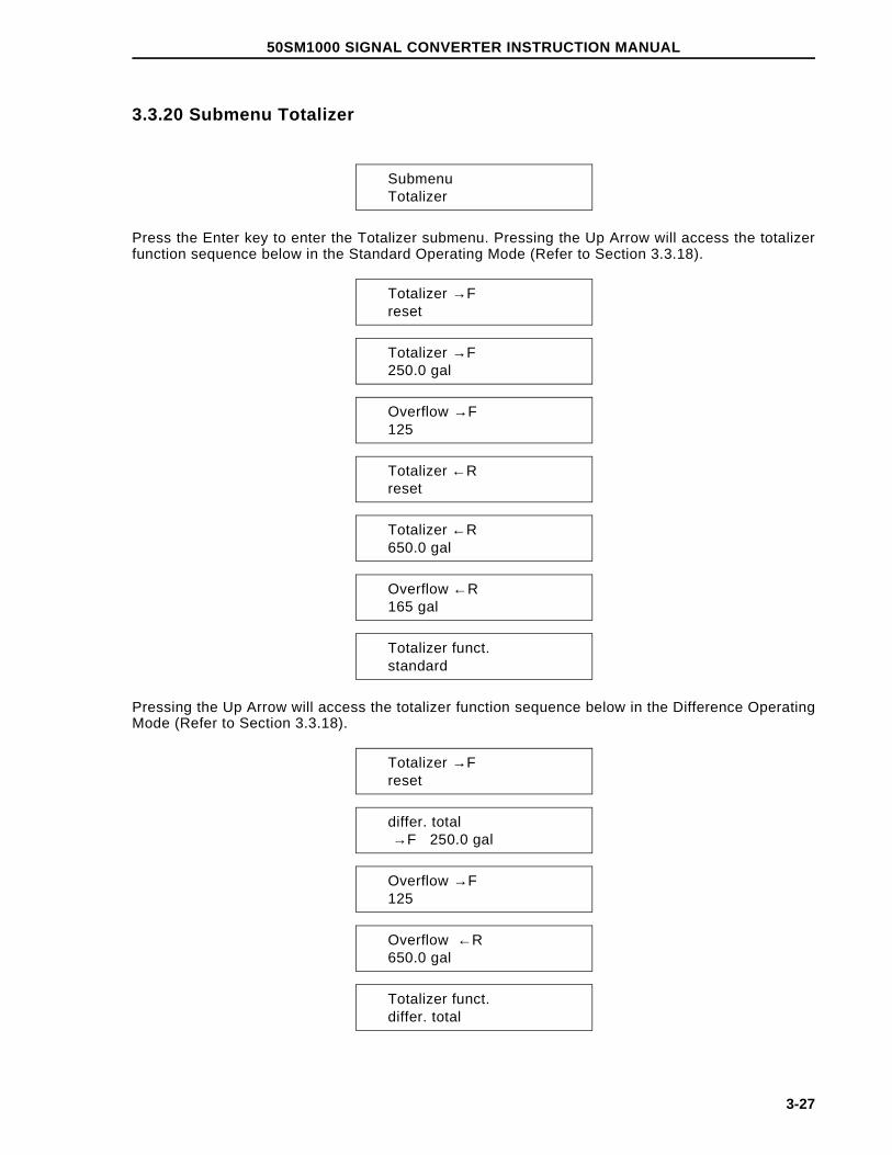
3.3.20 Submenu Totalizer
SubmenuTotalizer
Press the Enter key to enter the Totalizer submenu. Pressing the Up Arrow will access the totalizerfunction sequence below in the Standard Operating Mode (Refer to Section 3.3.18).
Totalizer →Freset
Totalizer →F250.0 gal
Overflow →F125
Totalizer ←Rreset
Totalizer ←R650.0 gal
Overflow ←R165 gal
Totalizer funct.standard
Pressing the Up Arrow will access the totalizer function sequence below in the Difference OperatingMode (Refer to Section 3.3.18).
Totalizer →Freset
differ. total →F 250.0 gal
Overflow →F125
Overflow ←R650.0 gal
Totalizer funct.differ. total
50SM1000 SIGNAL CONVERTER INSTRUCTION MANUAL
3-27

The Totalizer function is read-only and is determined by the totalizer operating mode selected in theOperating Mode Submenu (refer to Section 3.3.1.8)
The Forward and Reverse totalizers can be reset to zero individually (When in difference mode, onlythe Totalizer →F display appears and indicates the differential totalizer value). Toggle through themenu until the Totalizer → F reset message appears in the display. Forward or reverse flow will beindicated by "→ F" and "← R". Press the Enter key, and the appropriate counter will be reset to zero.
When the totalizer reaches its maximum count (9,999,999,) it "rolls over" and starts to count again atzero. When this occurs, the direction indicator (→F or ← R) at the left of the register and the units (ie.gal) at the right of the register will blink, and an overflow register will record the overflow. Maximumcount of the overflow register is 250. The cumulative total can be determined by multiplying thenumber in the overflow register times 9,999,999 and adding the value in the totals register. Theoverflow message is removed by toggling through the menu using the arrow key until "Totalizer reset"appears. At this time, pressing the enter keys will reset the totalizer, clear the overflow register, andthe blinking will stop.
Overflow Calculation Example: Overflow = 012
12 x 10,000,000 Units = 120,000,000 Units + present totalizer value 23,455 Units
120,023,455 Units
3.3.21 Submenu DisplayThe Submenu Display parameters can be configured by selecting the appropriate parameters listedbelow and entering the desired information. The display may be configured so that any availableinformation may be placed on either first or second line of the display.
In addition, a multiplex feature is available which can alternate any of two sets of parameters oneither line of the display. This feature can be activated by turning ON the line(s) of the display desiredfor multiplexing and then selecting the parameter to be shown. The display will alternate between thedisplay value and the multiplex value approximately every 15 seconds.
Scroll to the Display submenu using the Arrow keys or press the "7" direct access key. The followingdisplay will appear.
SubmenuDisplay
Press Enter again to gain access to the configuration parameters. The first display to appear isshown below.
1st line
50SM1000 SIGNAL CONVERTER INSTRUCTION MANUAL
3-28

Press Enter to change the information displayed on the top line of the display. Use the Arrow keys toscroll through the available parameters. The functions available are shown below:
Q [%] - flow rate as a percentage of range setting
Q [Bargraph] - left to right graphic of flow rate as a percentage of range, with nu-meric percentage to the right of the bar graph
TAG number - Allows assigning a meter location or identification number
Totalizer - Three totalizer modes are available:
• totalized forward and reverse difference flow (for Piston Pumpoperating mode only)
• forward flow
• reverse flow
Q [mA] - flow rate expressed as the number of mA present at the + and – analogoutput terminals
Q [unit] - flow rate in actual units selected in Section 3.3.4
Q [m/s] - Flowrate in meters per second
Reference p/n - Shows the digitized reference signal input in m/s (Only appears if the code number has been entered)
Signal p/n - Shows the digitized flow signal input and relative signal magnitude in m/s (Only appears if the code number has been entered).
Blank - Shows nothing on the display line (only for the bottom line)
Off - Only available for the multiplexed mode. Disables the multiplex feature.
When the desired parameter appears on the display, press Enter to make the selection and store it.Once the first line of the display is configured with the desired parameter, the bottom line may beconfigured in a similar fashion. Pressing the Up Arrow key will advance the submenu to the seconddisplay line as shown below.
2nd line
Select the desired parameter as discussed above for the first display line.
Press the Up Arrow key to advance to the 1st line multiplex display. This feature may be disabled(off) or enabled by pressing the Enter key and selecting a parameter to be multiplexed. If enabled,the two parameters selected for the display top line alternate every 15 seconds.
1st line multiploff
50SM1000 SIGNAL CONVERTER INSTRUCTION MANUAL
3-29

Similarly, multiplexing may be enabled for the second display line as well.
2nd line multiploff
3.3.22 Submenu Operating Mode
3.3.22.1 Operating mode
3.3.22.1.1 Standard
Standard operating mode should be selected for continuous flow measurement.
Operating modeStandard
3.3.22.1.2 Piston pumps (pulsating flow)
Piston pump mode should be selected for pulsating flows, such as with piston or diaphragm pumps).To obtain the best quality flow indication and output current, the Filter parameter (Refer to Section3.3.14) should be turned "on" when a pulsating flow condition exists. In order for the Filter to operate,Damping (Section 3.3.13) must be set greater than 2.4 seconds
Operating modePiston pumps
3.3.22.2 Flow DirectionSelects between measurement of Forward/Reverse flow direction or Forward flow only. If Forwardonly is selected, a flashing "←R" indication appears if reverse-flow occurs with an accompanying flowindication of 0%.
Flow DirectionFwd/Reverse
3.3.22.3 Flow Direction DisplayAllows reversal of the flow direction arrows on the display (equivalent to exchanging the electrodes).
Flow indicationStandard/opposite
3.3.23 Load and Store Configuration Data from the External EEPROMConfiguration data associated with a 50SM1000 and a specific flowmeter can be saved in theEEPROM located in the base of the converter enclosure. If the converter (plug-in) module is replacedor installed in another converter, the data can be retrieved without requiring re-entry.
50SM1000 SIGNAL CONVERTER INSTRUCTION MANUAL
3-30

3.3.23.1 Load Data from the External EEPROMWhen a new converter module is installed in the converter enclosure, the "load" command may beused to retrieve the data associated with the flowmeter. Calibration data for the converter module isnot saved in the external memory since it is associated with the module itself. Also, totalizer valuesare not saved in the external memory.
Load data from ext. EEPROM
3.3.23.2 Store Data in the External EEPROMData must be initially be placed in the external EEPROM using the "store" command. This will clearany erroneous data in the EEPROM. Any new configuration data will be automatically saved in theexternal memory as it is changed.
Store data in ext. EEPROM
3.3.24 Software LevelThe software level and the converter model number are shown in the display with the model numberand software release date on the top line and the EPROM identification and software level on thebottom line. Changes to the software can only be made by replacing the EPROM.
50SM1000 01/00D699B154U01 C.41
3.3.25 TAG NumberThe TAG number enables location identification of individual instruments if there are multiple instru-ments in the same installation. The TAG number is an alphanumeric entry which allows upper andlower case entries for diferentiation. A maximum of 16 alphanumeric characters may be entered.
TAG number
3.3.26 Code numberThe Code number is used to gain access to internal checks and adjustments that are not normallyperformed by operator personnel. These are reserved for factory and maintenance personnel.Instructions for these procedures are contained in Section 5.0. The Code Number display appears asshown below. Entering the Code Number automatically disables Program Protection and eliminatesthe need to enter the Program Protection Code in the event it has been changed from the "0" factorypreset value.
Code number
50SM1000 SIGNAL CONVERTER INSTRUCTION MANUAL
3-31

4.0 FUNCTIONAL DESCRIPTION
4.1 Basic Functions
The 50SM1000 Microprocessor-based signal converter is of the ac type, i.e., a power-line frequencysine wave is applied to the magnet coils of the flowmeter to establish the magnetic field. Theconverter receives the flow signal and a reference voltage from the Magnetic Flowmeter and convertsthese into analog and digital output signals.
4.2 Design Features
4.2.1 Micro-processor ControlledThe converter is microprocessor-controlled with nonvolatile memory. All operating parameters areconfigurable via the keypad on the converter and via an optional data link. During configuration, theconverter remains on line, and data is updated continually. The data base is updated at the time theENTER button is pressed to enter a parameter change.
4.2.2 DisplayThe liquid crystal display (LCD) is back lighted and contains two lines of 16 alphameric (5 X 7 dotmatrix) characters. The display is used to show flow rate on the top line in either percent of flow or indirect engineering units and totalization in direct engineering units on the bottom line (see Figure3-1). In addition, the display is used to show configuration data or error messages. Both the rateindicator and the seven digit totalizer are included in every converter as standard.
4.2.3 RangeabilityAny range from 0 to 100% can be selected provided the full scale value is between 33.33 ft/s (10 m/s)and 1.5 ft/s (0.5 m/s).
4.2.4 Bi-Directional FlowThe converter can be either unidirectional or bidirectional. Selection of the bi-directional mode ismade through software. This can easily be changed in the field. The standard mode is unidirectional.Instructions for this software change are contained in Section 5.0. In the bidirectional mode, theconverter will automatically display rate and totalization in forward and reverse directions. A pulseoutput option for each direction is available for retransmission to an external totalizer. A flow directioncontact is included in the 50SM1000 to indicate flow direction for the one analog output.
50SM1000 SIGNAL CONVERTER INSTRUCTION MANUAL
4-1

4.2.5 Flow DirectionThe flow direction is indicated at the left side of the display as ">F" for forward flow and "<R" forreverse flow. Totalization is also shown in this manner. The totalizer can be switched manually fromforward to reverse or vice versa by pressing the Tot. +/- key. The totalizer can be set to switchautomatically every 20 seconds by selecting MULTIPLEX DISPLAY "ON" from the configurationmenu.
There is one analog output available. Flow in the reverse direction is indicated by the same analogsignal as the forward. To make the distinction between forward and reverse flow, contact closures areprovided in the 50SM1000. In a two pen recorder, for example, one pen could be used to record flowwhile the second pen could rest at zero with the contact open and could be elevated to some positivevalue when the contact closes. Thus, the position of the second pen would indicate the direction offlow. If the analog signal goes to a computer or CHAMELEON type instrument the contact closurecondition is easily recognized as an indication of flow direction.
4.2.6 Output Signals
4.2.6.1 Analog OutputA 4-20 mA dc output signal into 0-500 ohms is standard and is always available regardless of whichoutput options are selected.
4.2.6.2 Optional OutputsEither a scaled pulse output or a data link can be selected.
4.2.6.3 Scaled PulseThis is a 24 V dc pulse that can operate a minimum load of 150 ohms. It can be used to drive anelectromechanical counter at 0-10 Hz with a 50 millisecond pulse width or a high speed electronicdevice at 0-4 kHz with a 50 microsecond pulse width. The pulse width can be adjusted as a part ofthe data base and does not require a hardware change.
4.2.7 Data LinkThe data link is the hardware and software by which the data base may be examined. The data baseis a collection of elements in the converter memory which may be either altered or examined throughsoftware. In addition, the data base represents the information the instrument is working with in thecourse of its normal computations. A few of the parameters included in the data base are calibrationfactor, range setting, damping value and pulse width. The data link consists of two transmitting andtwo receiving wires which pass serial data at 110 bits per second up to 28,800 bits per second (110Baud to 28.8 kBaud). It does not carry the analog output signal from the converter. The analog signalis carried over its own wires directly to the receiving device (recorder, controller, indicator, computer,etc.) in the normal manner. There are two industry standard hardware arrangements for the data linkoption. They are RS232C and RS485.
RS232C interface is probably the most common serial data link in use today. It permits communica-tion between two devices normally within fifty feet of each other at baud rates up to about 9600.Devices are available to convert from RS232C to RS485 to allow connection of more than oneconverter to a single computer and to transmit well beyond fifty feet.
RS485 interface is a high speed link used by the company’s MICRO-DCI instrument line as well asother intelligent instruments. It permits any transmitter to be shut off or "tri-stated" when not in use.For instruments such as the SUPERVISOR, it means that up to 32 instruments may ’talk’ over onedata link. This link can send data at 28.8 kBaud over lines up to 4000 feet long. Two key padselectable communication modes are available. They are MICRO-DCI Binary and ASCII.
50SM1000 SIGNAL CONVERTER INSTRUCTION MANUAL
4-2

4.2.7.1 ASCIIIn the ASCII mode, a sequence of ASCII characters is sent back and forth.
4.2.7.2 MICRO-DCI BinaryThis mode is the most powerful communications scheme available. It will be recognized by thefollowing instruments:
1) SUPERVISOR & SUPERVISOR-PC (53SU1000 & 53SU5000).2) MS-DOS Personal Computer with 53HC3300 software3) DCI SYSTEM using I-COM/X and SUPERVISOR
In the binary mode, information is compressed so that it is sent approximately twice as fast as in theASCII mode. However, this format will not be recognized by "dumb" terminals. The binary modeinterface provided permits the user to write programs which automatically extract or change data. Ineach of the above cases, these programs are written in a different notation, with the MS-DOSPersonal Computer version using BASIC with customized subroutine calls.
4.2.8 HART InterfaceThe optional HART protocol system, when supplied, permits simultaneous 4-20 mA and digital signaltransmission on the same 2-wire cable. With this protocol, process parameters such as instantane-ous flow rate and cumulative total flow, or operating conditions such as alarm values, can bemonitored or altered by an external "smart " device, e.g., a host computer. This interface allows the50SM1000 data base to be uploaded into the host computer. Operating parameters which would onlybe changeable at the 50SM converter can be scanned and remotely reconfigured.
Software and hardware are optionally available to implement a HART Protocol information exchangebetween the converter and a HART Protocol master device. This data link permits continuousmonitoring of process variable and totalized flows and provides for configuration of the following:
Values and units for range Pulse factor and units for totalizers as well as reset capabilityDamping, noise reduction, low flow cutoff valueEmpty pipe detector setupAlarm fail safe conditionConverter tag name and record informationCalibration of the analog (4 - 20 mA) output
The following parameters may be displayed but not configured:
Meter size and calibration factorInstrument type (50SM1000) and manufacturerTotalizer overflow values
Refer to the HART Model 275 Communicator instruction manual for detailed information regardingapplication of HART Protocol.
When implementing the HART protocol, the control computer is the master and the field transmitterthe slave. In addition to this primary master a second master (such as the Model 275 Hand-HeldCommunicator) can become active. Data is transmitted at 1200 baud, with the serial informationbeing encoded and detected as outlined in the Bell 202 standard.
50SM1000 SIGNAL CONVERTER INSTRUCTION MANUAL
4-3

4.2.8.1 HART Firmware Menu SequenceThe HART firmware organization differs slightly from the standard firmware organization shown inFigure 1-3 and detailed in Section 3.3. Some features are not available with HART firmware. Thefollowing is a menu sequence listing for the HART Protocol version firmware, number D699B164U01,Rev. X.10. Refer to the section number listed beside the menu item for information describing itsfunction.
Menu Item: Comments:
Program Protectionon
Section 3.3.1
LanguageEnglish
Section 3.3.3
Meter Size20 mm 3/4 in
Section 3.3.4
Range unitgpm
Section 3.3.14.1
Range DN 10 m/s268.000 gpm
Section 3.3.5
Range100.000 gpm
Section 3.3.6
Totalizer Unitgal
Section 3.3.14.2
Pulse Factor1.0000/gal
Section 3.3.7
Pulse Width30.000 ms
Section 3.3.8
Max. Alarm130%
Section 3.3.15.2
Min. Alarm20%
Section 3.3.15.3
Low Flow Cut-off1.0000%
Section 3.3.9
50SM1000 SIGNAL CONVERTER INSTRUCTION MANUAL
4-4

Menu Item: Comments:
Damping10.0000 s
Section 3.3.10
Filteron/off
Section 3.3.11
Density1.0000 g/cm3
Section 3.3.12
Flow (indication)gpm
The upper line of the display is used to indi-cate flowrate in the monitoring mode. It can beexpressed in % or in direct engineering units.Step through the menu until Flow appears onthe upper line of the display.
The selections available for this parameter areengineering units, percent ( %) and m/s (me-ters/second). Press the enter key, and the cur-sor will appear to the right of "gpm". Nowpress the arrow key , and the value will changefrom the engineering units shown to % or m/s.Press the enter key, and the change is enteredinto memory.
System Zero Adjust0.0000 Hz
Section 3.3.13
SubmenuOperating Mode
Section 3.3.22
SubmenuCurrent Output
Section 3.3.16
SubmenuData Link
Section 3.3.17
SubmenuFunction Test
Section 3.3.18
SubmenuDetector e.pPipe
Section 3.3.19
Totalizer >Freset
Section 3.3.20
50SM1000 SIGNAL CONVERTER INSTRUCTION MANUAL
4-5

Menu Item: Comments:
Overflow >F000
Section 3.3.20
Totalizer <Rreset
Section 3.3.20
Overflow <R000
Section 3.3.20
Error Log.1...5...8...
Section 3.3.15
Multiplex Displayon/off
Section 3.3.21
Load data fromExt. EEPROM
Section 3.3.23.1
Store data inthe ext. EEPROM
Section 3.3.23.2
50SM1000 09/96D699B164U01 X.10
Section 3.3.24
Code Number****
Section 3.3.26, 5.5.1
Options------------------------
Available selections are none (-------------) orDetector e.pipe
Qmax DN Velocity10 m/s
Section 5.5.5
Span Adjust >F80.000%
Section 5.5.3.1
Span Adjust <R-80.00%
Section 5.5.3.2
Zero Adjust 0.000
Section 5.5.3.3
50SM1000 SIGNAL CONVERTER INSTRUCTION MANUAL
4-6

Menu Item: Comments:
Adjust Iout 100%101.00
Section 5.5.3.5
Adjust Iout 20%19.000
Section 5.5.3.6
* Calibration *off
Section 5.5.3.4
Adjustment ofIntegrators
Section 5.5.3.7
Range DNfixed/programable
Section 5.5.6
Flow Directionforward/reverse
Section 3.3.22.2
Instrument no.0
Section 5.5.9
Priv. Distributor018
This is a read-only parameter and shows thePrivate Distributor Number assigned to thecompany.
Mains Interrupt3
Section 5.5.12
** Reset ** Section 5.5.10
Output Data Section 5.5.13
Initialization Section 5.5.14
Analog Range1 m
Section 5.5.11
Excitation60 Hz
Section 5.5.4
50SM1000 SIGNAL CONVERTER INSTRUCTION MANUAL
4-7

4.2.9 Optional Features on Base BoardThe base board used in the 50SM converter provides several functions, including the following:
Customer connections to primary and other field wiringReference voltage termination for 81 and 1000 ohm unitsConfiguration memoryRelays or optocouplers for alarm and direction optionsConnection interface to converter plug-in module
The customer connection board contains four 16 pin IC type sockets which accommodate relays oropto couplers, as specified in the model number. Direction indication is always accomplished using aform C (SPDT) relay, A903. Figure 6-1 shows the locations of the sockets for A901 through A904.Excepting A903, the operation of the relay contacts (normally open or normally closed) may beselected using the switches adjacent to them.
The following is a listing of terminals associated with the various contact outputs and their operatingmodes:
Option Terminals Operationerror alarm V5(E)*, V6(C)* closed with no errors (Pos. "1")**
direction 44,45(com),46 45 to 46 closed forward, 45 to 44 closed reverselow threshold P3(E), P4(C) open at no alarm (Pos. "1")high threshold P1(E), P2(C) open at no alarm (Pos. "1")
* (E)= emitter, (C)= collector (positive)** Pos. "1" applicable for relay option only
4.2.10 Reference Voltage and ImpedanceProper measurement of flow rate requires not only a signal from the electrodes, but also a signal fromthe primary which is related to the coil excitation current, referred to as the reference voltage. Thereference voltage is developed by one of two methods, depending on the type of primary. For ModelDS21 & 10DS3110 flowmeters, a current sensing resistor is placed directly in series with the coils,which are driven by an isolated 60 V ac transformer winding. This reference voltage, which isnominally 100 mV rms, is present at terminals 16 and 3 of the flowmeter. Flowmeters 10D1418,10D1430, 10D1462 and 10D1472 have their coils operated directly from the power line, and thereference is isolated by a current transformer requiring a precision terminating resistance of either 81ohms (10D1418/10D1430) or 1000 ohms (10D1462/10D1472). The 50SM1000 converter has theappropriate components placed on its base board to accommodate the 81 or 1000 ohm referenceloads. These are connected to terminals 6 and 7 and provide voltage division down to a nominal 100mV rms level, which can be measured at terminals 16 and 3.
Switch S901 (refer to Figure 6-1) on the base board is used to switch the 81 or 1000 ohm referencesinto terminal 16 of the converter so that their measurement will take place, and must be left openwhen using a reference that comes directly into 16, as when calibrating the converter.
The menu selection in the "operating mode" or "submenu primary" provides the proper calculation forthe divided reference voltage when in the 81 ohm, 1000 ohm, or undivided mode. In all cases, thevoltage measured at terminals 16 and 3 must be in the range of 50 to 150 mV rms or a referencevoltage error message will appear.
50SM1000 SIGNAL CONVERTER INSTRUCTION MANUAL
4-8

The following chart summarizes the above information:
MODELNUMBER
SUBMENU PRIMARYSELECTION
NOMINAL LOADRESISTANCE
S901SETTING
10D1418 10D1422 81 Ω Closed10D1430 10D1422 81 Ω Closed10D1462 10D1462 998.2 Ω Closed10D1472 10D1472 998.2 Ω Closed
10DS, DS21 10DS3110 N/R Open10D1416 N/A Cannot be used with this model
Refer to Figure 6-1 in Section 6.3 for component locations.
4.2.11 PowerRefer to the converter instrument tag for specific power requirements.
Voltage 115 V ac ±10% or230 V ac ±10%
Line Frequency 47 - 53 Hz or56 - 64 Hz
Power Consumption < 30 VA (applies to the converter only, but includesthe excitation current for models DS21, 10DS3111and 10DS3112)
50SM1000 SIGNAL CONVERTER INSTRUCTION MANUAL
4-9

5.0 CALIBRATION
5.1 General Discussion
NOTEThe 50SM1000 signal converter should never require recalibration, unless
a hardware failure has occurred. If the NVRAM proves defective, calibrationdata must be reentered. In the event of component failure, existing
calibration data may no longer be valid.
One notable feature of the type 50SM1000 converter is that it can be configured independent of anyparticular primary. The design of the microprocessor-based 50SM1000 converter permits configura-tion and calibration of the converter prior to its installation.
Each converter is configured and precisely calibrated at the factory in accordance with customerspecified flow parameters.
Since the flow metering system is precalibrated, it is generally ready for on-line service as received.In the event that the specified system flow parameters or engineering units are to be changed, thesignal converter must be reconfigured to agree with the revised flow values.
Signal converter performance can be verified periodically using the procedure described in Section5.3. If problems are experienced which may be originating with the Signal Processor, use theperformance verification procedure first. Recalibration should be done only when it has been deter-mined that it is actually required. If calibration is necessary, it can be done using the proceduredescribed in Section 5.7.
Essential calibration data is recorded and listed on a data tag that is attached to the side of atransformer in the signal converter assembly. The calibration data provided can be used to restorethe signal converter to a calibrated condition when data held in the NVRAM has been corrupted. RAMcorruption can result from a lightning strike or severe electrical disturbance near the installation site.Before recalibration, data from the external EEPROM should be uploaded. If data in the externalEEPROM is also corrupted, all of the calibration data must be re-entered. If the signal converter hasmalfunctioned and a defective component must be replaced, the calibration data is no longer valid;the unit must be recalibrated as described in this section.
50SM1000 SIGNAL CONVERTER INSTRUCTION MANUAL
5-1

5.2 Test Requirements
5.2.1 EquipmentTest equipment needed for signal converter calibration/testing includes the following:
1) Model 55XC2000 or 55XC4000 Simulator with ac adaptor
2) Electronic Totalizer/Frequency Counter (0-10 kHz)
3) Digital Voltmeter (typically, 0-10 V dc)
4) Electromechanical Counter or Electronic Totalizer (as applicable for 0-15 Hz* max, or 0-4 kHz)
5) 250 ohm +0.05%, 1/2 W, precision resistor
*assumed maximum count rate of electromechanical counter
Typical test wiring is shown in Figure 5-1. Interconnection wiring diagrams for the 50SM1000 signalconverter are included in the Installation Section and should be used to supplement this discussion.
Use of the company’s Model 53SU1000 SUPERVISOR, 53SU5000 SUPERVISOR-PC, or similarintelligent data handling equipment will be needed for interfacing with the RS 232C or RS 485 I/Osignals, when supplied. Signal wiring is shown on the applicable system interconnecting diagram.When communication is implemented via the HART Protocol, applicable interconnection diagramsare contained in the technical literature provided for the particular communicator; e.g., the Hand-HeldComputer (IB 50HC1000).
5.2.2 Signal Simulator
The Signal Simulator provides an adjustable process variable flow signal suitable for on-site perform-ance and accuracy tests of the 50SM1000 signal converter.
The simulator signal range can be preset via 3 decade type (0-9) digital switches. These presetswitches permit precise setting of the simulated flow signal over a range of 0.00 to 9.99 m/s in 0.01m/s increments. A two position switch changes flow from forward to reverse for bi-directional flow. ACMR switch for verification of common mode rejection is also provided.
The verification procedure is described in Section 5.3.
5.2.2.1 55XC2000 SimulatorAn adaptor with shielded cables is supplied for interconnecting the 55XC2000 Simulator with theconverter.
Attachment of the test cables from the 55XC2000 Signal Simulator to the signal converter isillustrated in Figure 5-1.
50SM1000 SIGNAL CONVERTER INSTRUCTION MANUAL
5-2

FIGURE 5-1. TEST WIRING USING 5XC2000 SIGNAL SIMULATOR
CBI3004-1
50SM
1000 SIG
NA
L C
ON
VE
RT
ER
INS
TR
UC
TIO
N M
AN
UA
L
5-3

5.2.2.2 55XC4000 Signal SimulatorThe signal simulator is supplied with an interface adaptor that includes test cables that mate withreceptacles provided on the signal converter assembly.Typically, when the test cables are con-nected, power for operation of the converter is supplied by the signal simulator.
Attachment of the test cables from the 55XC4000 signal simulator to the signal converter is shown inFigure 5-2.
The converter power supply should correspond to the simulator power supply. The AC line plug(mains plug) should be connected so that the "Phase" lamp is energized. If power supply is DC, takecare to observe the proper polarity as indicated in Figure 5-2.
FIGURE 5-2. TEST WIRING USING 55XC4000 SIGNAL SIMULATOR
50SM1000 SIGNAL CONVERTER INSTRUCTION MANUAL
5-4

5.2.3 Signal Converter Disassembly
Should it become necessary to disassemble the signal converter for calibration and/or testingproceed as outlined below.
5.2.3.1 Removing the Signal Converter from the base
WARNINGEquipment powered by an ac line service constitutes a potential lethal
electric shock hazard. Installation and servicing of the magneticflowmeter and signal converter should only be attempted by a qualified
electronics technician. Make certain that the power input leads aredisconnected from the operating circuit before attempting electrical
connections.
1) To remove the converter cover, unscrew the four mounting screws located in the cornersof the cover. These are captive-type screws and should not be removed from the cover.Store the cover for reassembly.
2) On top of the Digital board, unscrew the four screws that pass through the standoffs located near the corners of the converter assembly. Lift the converter assembly carefully sothat the interconnecting terminal connectors between the converter assembly and the termi-nal board in the base will not be damaged. Save all mounting hardware.
5.2.3.2 Disassembly of the Signal ConverterTo gain access to the Analog Board, it may be necessary to separate the Analog and Digital boards.If applicable, proceed as outlined below.
1) Unscrew the four hex nuts that secure the Digital Board to the standoffs. Save all hard-ware.
The Digital board can then be lifted slightly and tilted up (away) from the Analog board.
2) If it is necessary to separate the Analog and Digital boards, disconnect the interboard ca-ble.
The converter assembly can be reassembled by performing the above procedure in reverseorder.
50SM1000 SIGNAL CONVERTER INSTRUCTION MANUAL
5-5

5.3 Performance Verification
To verify calibration of the converter, use either the 55XC4000 Simulator or 55XC2000 Simulator withac adaptor. If using the 55XC2000 Simulator with ac adapter, connect the simulator as shown inFigure 5-1.
NOTEPrior to performing verification and/or calibration, the S901 switch
located on the terminal board must be set in the open (unhooked) position(refer to Figure 6-1) and the flowmeter selection (Section 3.3.4) must be
10DS2110/3110. Upon completion of the calibration verification procedure,return the S901 switch and the flowmeter selection to their previous opera-tional settings. For normal operation, the S901 switch must be set in the
closed position (hooked) for all flowmeters except the 10DS3111 and DS21(12 inch or less), in which case it must be open (unhooked).
CAUTIONWhen the dynamic test is to be made in the customer’s instrumentservice shop, especially if the total volume processed is needed for
inventory or billing purposes, the total volume should be logged beforedisrupting electrical interconnections.
Enter a range value on the 3-digit range selector and read the output on the converter assemblyliquid crystal display or metering devices connected to the Simulator output(s).
For ... Qmax DN velocity = 33.33 ft/s
The indicator reading can be calculated as follows:
% Indicator Display = m/s x Cal Factor x 100 10.159 Range > F or < R
where, m/s = Simulator velocity setting
Alternatively, if the converter is set up for max flow velocity (QmaxDN) = 10 m/s, then the % Indicator Display calculation would be as follows:
% Indicator Display = m/s x Range DN x 100 10.00 Range > F or < R
For example, assume the primary is a 2 inch meter with a Cal Factor of 268.372 gpm at 33.33 ft/s,that the Signal Simulator is set for 5.00 m/s, and Range > F is preset for 250 gpm max, then:
% = 5.00
10.159 x
268.372250
x 100
= 52.8
50SM1000 SIGNAL CONVERTER INSTRUCTION MANUAL
5-6

If the current output is preset for 0-20 mA* and the load resistor (Rx) is 250 ohm (refer to Figure 5-1Test Wiring), then the voltage reading displayed by the DVM should be:
E = Imax x Indicator % (Rx) 100
= 0.020 x 52.8100.0
(500)
= 2.64 V dc
The flow velocity in ft/s at the operating flow rate can be calculated as shown below.
ft/s = Oper(gpm) x 33.33 Calfactor(gpm)
Using values given in the above example,
ft/s = 250 x 33.33 = 31.0 268.372
To convert velocity in ft/s to m/s,
m/s = ft⁄s
3.2808
typically,
m/s = 31.0
3.2808 = 9.45
When satisfactory performance has been demonstrated, select the desired current output span (0-20/4-20/0-10/2-10 mA) before returning the converter to service. Standard output is 4-20 mA.
* HART units cannot be changed when output is set at 4-20 mA.
50SM1000 SIGNAL CONVERTER INSTRUCTION MANUAL
5-7

5.4 Initialization
The item in the calibration menu sequence called "Initialization" should be treated with caution. If thisitem is selected all parameters are set to the default values, replacing the factory-installed settings.Therefore, extreme caution should be exercised in using "Initialization". In general, "Initialization"need only be performed if there has been a loss of data in NVRAM memory which cannot berecovered from the external EEPROM. If a record of the calibration data is available from the tag, thedata should be re-entered following the initialization. Otherwise, the unit must be calibrated again toplace it back to within specified accuracy.
5.5 Calibration Procedure
NOTEThe 50SM1000 signal converter should not require recalibration in its life-time, unless a hardware failure has occurred. If the NVRAM and EEPROMprove defective, calibration data must be reentered. In the event of compo-
nent failure, existing calibration data may no longer be valid.
The 50SM1000 converter software includes some configuring routines whose use permits specialentries specific to the calibration of the device to be set. When the calibration mode has beeninvoked, it is possible to access parameters normally blocked because they are either linked tooptions not installed or because they are not compatible with other parametric settings.
For example, the software includes an automatic module identification for the RS485 and RS232serial interface modules. When configuring the 50SM1000, the parameters "Instr. address","Baudrate" and "Communication" in the "Data link" submenu are programmable only if a serialinterface module has been installed. The absence of such a module is indicated by "ERROR-NOTAVAILABLE" on the display whenever an attempt is made to call up that parameter. However, in thecalibration mode, any of these menu items may be accessed and changed even if the proper modulehas not been installed.
NOTEThis procedure has been prepared for use with software version C.41 of the50SM1000 signal converter. Other versions will be similar but not necessar-
ily identical and may have features different from those discussed in thissection.
CAUTIONOnly experienced electronic technicians should attempt to calibrate the
signal converter. Erroneous calibration will result in unsatisfactoryperformance.
50SM1000 SIGNAL CONVERTER INSTRUCTION MANUAL
5-8

CAUTIONSome of the surface mounted IC devices used in the signal converterare static sensitive and may be damaged by improper handling. When
adjusting or servicing the signal converter, use of a grounded wriststrap is recommended to preclude inadvertent damage to the integral
solid state circuitry.
NOTEPrior to performing verification and/or calibration, the S901 switch locatedon the terminal board must be set in the open (unhooked) position (refer to
Figure 6-1). For normal operation, the S901 switch must be set in theclosed position (hooked) for all flowmeters except the 10DS3111 and DS21
(12 inch or less), in which case it must be open (unhooked).
5.5.1 Code NumberAccess to special functions including calibration parameters is achieved by entering the proper codenumber. In order to enter the factory calibration mode it is necessary to enter the number 1000. Thecalibration mode is locked out with the entry of a number other than 1000 or after a power-on reset.Program protection must be "OFF" in order to make this entry.
Code number 1000
5.5.2 OptionsThis menu enables selection of optional parameters and is configured at the factory. Availableselections are:
• none
• Empty p.
• RS232
• RS232 + Empty p.
• RS485
• RS485 + Empty p.
• Pulse
• Pulse + Empty p.
Configuring the serial interface options will cause the Data Link submenu to appear in the menustructure (Refer to Figure 1-3). Configuring the Empty pipe detector option will cause the Empty PipeDetector submenu to appear in the menu structure (Refer to Figure 1-3).
50SM1000 SIGNAL CONVERTER INSTRUCTION MANUAL
5-9

5.5.3 Submenu Instr. Adjust
5.5.3.1 Forward Flow Instrument AdjustThe following procedure details the instrument adjust procedure for the forward flow direction (shownbelow as not adjusted).
NOTEThe converter range should be changed to correspond with the
"Cal Factor" value for any of the remaining steps.
span adjust → F83.28%
This parameter determines the calibration of both the display and the scaled pulse output and maybe set by two different methods. First, a value may be entered manually when the following menuappears following the "Enter" operation:
Span adjust → F manual ?
The proper value is that which will cause the display readout to indicate 99.90% of the cal factor withan input of 9.99 m/s. This number is present on the converter data tag affixed to the powertransformer on the converter assembly and will be valid unless there has been replacement of analogcircuit hardware.
In order to automatically adjust the span, a flow simulator type 55XC4000 or 55XC2000 with adaptorfor the AC converter must be available. Applicable test wiring is shown in Figure 5-1. The Simulatormust be set to 9.99 m/s and switched to the forward flow mode. After scrolling to the "automatic"menu item and pressing "Enter", the adjustment progresses and the display will show:
Adjust 000 000
The left-most digits will immediately begin counting up to a value of 256. When the 256-count isreached, the right-most digits will be incremented to read "001" and the left-most digits will roll overto "000" and begin counting to 256 again. When the right-most counter reaches a value of "008", theadjustment is complete and the converter reverts to monitoring mode; the display reading will be99.9% (+/- 0.1%). Push the "↑ " button to display the value computed such as:
Span adjust >F 83.28%
After approximately 20 seconds the converter will return to monitoring mode.
5.5.3.2 Reverse Flow Instrument Adjust
Span adjust ←R -83.5%
50SM1000 SIGNAL CONVERTER INSTRUCTION MANUAL
5-10

This adjustment is performed in the same manner as that for the forward direction except that in theautomatic mode the simulator is to be set at 9.99 m/s "Reverse". Refer to forward flow instrumentadjust (Section 5.5.3.1) for instructions.
5.5.3.3 Zero Adjust
Zero adjust 5.0
Zero may be adjusted manually or automatically. In order to manually set zero, enter an input of"0.10" m/s FWD, and note the reading obtained. Then enter an input of "0.10" m/s REV, and note thereading obtained. Enter a value into the "Code 1000" Zero adjust menu which ultimately causes thesereadings to be equal and opposite.
Example:
Enter an input of 0.10 m/s FWD = Output.98% of 10 m/s spanEnter an input of 0.10 m/s REV = Output -1.04% of 10 m/s spanEnter an input of -3 Hz as a manual zero.Outputs will then be +/- 1.01% respectively.
5.5.3.4 Calibration (Factory use only)
Calibrationoff
5.5.3.5 Adjust Iout 20mAFor HART applications, the use of a Hand-Held Communicator is recommended while performing a"DAC Adjust" function.
Adjust Iout 20mA20.000
Entering this item causes the converter to produce an uncalibrated 20mA output current (if theselection is set to 20.000mA). This current will produce a nominal 5.00 volts across a precision 250ohm resistor connected across the current output terminals. If the resulting output is inaccurate bymore than .02mA (0.1%), reset the parameter to 20.00mA and re-select it. To determine thecorrected current value to enter, measure the voltage developed across the 250 ohm resistor andcalculate the corrected current using the equation below.
Example: When the above menu was selected, the value measured across a precision 250 ohm loadresistor was 5.056 volts. This value divided by 250 ohms yields the corrected value that must beentered, which is 20.224. In equation form, this becomes:
Measured Voltage x 1000 = corrected value (in mA) 250 Ω
Enter the corrected mA value calculated above into the Adjust Iout 20mA menu to calibrate the 20mAoutput current.
50SM1000 SIGNAL CONVERTER INSTRUCTION MANUAL
5-11

5.5.3.6 Adjust Iout 4mAThe 4mA output current calibration is performed in a similar manner to the 20mA adjustment inSection 5.5.3.5.
Adjust Iout 4mA 4.000
Selecting this menu causes the converter to output an uncalibrated 4mA current which should give anominal value of 1.0 volts across a precision 250 ohm resistor. Measure the actual voltage developedacross the resistor and calculate the corrected current value using the equation below.
Measured Voltage x 1000 = corrected value (in mA) 250 Ω
Enter the corrected mA value calculated above into the Adjust Iout 4mA menu to calibrate the 4mAoutput current.
NOTEWhen all calibration steps are completed, record the respective data and
keep it with the converter for future reference.
5.5.3.7 Adjustment of Integrators
Adjustment ofintegrators
This function is preset at the factory and requires no further adjustment.
5.5.4 ExcitationExcitation 60 Hz
This is a read-only parameter that measures and displays the power line frequency (50 or 60Hz).
5.5.5 Maximum VelocityVelocity at Cal Factor
QmaxDN velocity 10 m/s
This parameter is used to select either 10 m/s or 33.33 ft/s as the velocity corresponding to Calfactor. Span calibration adjustments of both frequency and current outputs are to be made with thisparameter selected to 10 m/s and the Span Adjust display set to indicate flow in "%".
Select 10DS3110 in Submenu Primary (Section 3.3.4).
50SM1000 SIGNAL CONVERTER INSTRUCTION MANUAL
5-12

5.5.6 Cal-FactorCal-factprogramable
Two selections are available for this parameter:
• fixed
• programmable
This parameter is factory-set, usually to the "programmable" mode. For more information on Cal-Fac-tor, refer to Section 3.3.5.
5.5.7 Range < .05 Range DNAvailable selections are on/off.
Range<.05RangeDNoff
5.5.8 Keypad OldThis function is intended for a user with old hardware who desires to update to new C.41 firmware. Inmost cases it can be set to "off".
keypad oldon / off
5.5.9 External Zero Adjust
Ext. zero adjustcontact A1
Selections available are:
• contact A1
• contact 22 + 31
This menu selects the terminal board contacts to be used for the external zero adjust function.
5.5.10 Instrument Number
Instrument no. 0
All converters have a factory installed sequential number, reflecting their relative time of manufac-ture. This is a factory-set parameter and should not be altered.
50SM1000 SIGNAL CONVERTER INSTRUCTION MANUAL
5-13

5.5.11 Reset
**RESET**
This function executes a " warm " CPU hardware reset, after which switch positions, hardwareoptions, etc. are polled. This function is normally completed whenever power is applied to theconverter. The power line interrupt counter is not incremented and the code number is not clearedwhen "RESET" is invoked.
5.5.12 Analog Range1 m
Indicates relative flow velocity signal in m/s (1m, 2m, 4m, 8m)
5.5.13 Mains InterruptRecords the number of times the unit has been powered
Mains Interrupt 0
5.5.14 Output data
NOTE Before initiating this function, verify that the communication mode in thedata link submenu is set to "ASCII". If this is not done, the converter will
hang up and suspend all signal processing until the power is cycled off and on.
This function outputs all the converter’s configured data in plain ASCII text to both the converterdisplay and the data link simultaneously. This can be useful in establishing data link protocol orsaving all device parameters.
5.5.15 InitializationIf this item is selected all parameters are set to the default values, replacing the factory-installedsettings. Therefore, extreme caution should be exercised in using "Initialization". In general, "Initiali-zation" need only be performed if there has been a loss of data in NVRAM and/or EEPROM memory.If a record of the calibration data is available from the tag, the data should be re-entered following theinitialization. Otherwise, the unit must be calibrated again to place it back to within specifiedaccuracy.

5.5.16 Initialize External EEPROM
Init. ext. EEPROM
Initializes the external EEPROM, located on the connection board assembly, to its default values.Identical in operation to the corresponding function in the 50XE and M2 converters.
5.5.17 Parameter UpdateThe last item in the calibration menu sequence is "Parameter Update".
This function is performed automatically at power-up if a firmware upgrade has been performed in theinstrument. It automatically polls data locations stored in the NVRAM and moves them to newlocations if necessary.
50SM1000 SIGNAL CONVERTER INSTRUCTION MANUAL
5-15

6.0 MAINTENANCE
6.1 General Discussion
As the 50SM1000 signal converter is a microprocessor based instrument, all computations, datamanipulation and sequencing operations are software controlled. Display of flow rate and thecumulative total flow are performed automatically concurrent with flow through the associatedmagnetic flowmeter. As the magnetic flowmeter has no moving parts that are subject to mechanicalwear and the signal converter has no operating controls that require field adjustment, there are norecommended periodic tests to be performed. As a result, routine system maintenance is notrequired.
If in the course of operation the signal converter does not perform as expected, it is common for theoperator to first suspect that the software configuration is faulty. Although this may occasionally betrue, it should be emphasized that the EPROM and NVRAM memory devices used in the signalconverter are highly reliable. Should a malfunction be evident, see if the CPU light located on thekeypad is energized. When the CPU light is energized steadily (not blinking), it is probable that themicroprocessor and associated memory devices are functional. In this case, proper operation of themagnetic flowmeter should be established before troubleshooting the signal converter. Proper opera-tion of the converter can be confirmed as described in the Calibration Section.
NOTEDue to the complexity of troubleshooting micro-processor based
instruments, maintenance below the assembly level is not recommended.
If troubleshooting of the signal converter assembly is attempted, it should be noted that many of theCMOS type IC chips used in this assembly are static sensitive devices that can be internallydamaged if not handled properly. Also, caution must be used when connecting test probes, as evena momentary accidental short may damage or destroy an integrated circuit. Further, althoughprotection is provided against electro-static effects by built-in circuitry, the following precautionsshould be taken if it is necessary to handle the 50SM1000 converter pc assembly:
1) Ground all test equipment.
2) Technicians should use grounding-type wrist straps.
3) The surface of the service bench should be grounded to preclude static electricbuild-up.
4) All CMOS devices should be stored or transported in materials that are anti-static(do not use ordinary plastic wraps or bags). Typically, protection of the converterassembly can be effected by first covering the pcb assembly with aluminum foil andthen providing an outer wrap of heavy paper.
50SM1000 SIGNAL CONVERTER INSTRUCTION MANUAL
6-1

When a system malfunction is evident, the first step is to determine whether the problem is hardwareor software related. If the signal converter appears to respond normally to functional operations suchas those expected to occur during the course of parameter monitoring, self test procedures, etc., andsystem constants can be verified as correct, but the displayed process values are wrong, then properoperation of the primary meter should be verified.
When the signal converter exhibits total failure (no display can be obtained on the LCD), thenpossible loss of the external power source or an internal hardware malfunction could be the cause. Avolt-ohm analysis will quickly indicate whether the problem is external or internal. Use of a conven-tional V-O-M is considered adequate for voltage and resistance analysis. An electronic frequencycounter and oscilloscope will also be useful for verifying the output frequency rate, signal tracing, etc.
In the event of a hardware malfunction, a replacement converter assembly can be quickly substitutedfor the defective assembly, thereby minimizing system downtime. The manufacturer offers a factoryrepair/exchange program to facilitate replacement of a defective electronics module, i.e., the com-plete signal converter assembly. Under this repair/exchange program a fixed price will be charged tothe account of the customer for replacement of defective equipment, with appropriate credit issuedwhen the repairable unit is received by the factory (shipping charges prepaid).
NOTEWhen communicating with the factory regarding a replacement converter, itis important to reference the complete instrument serial number and modelnumber to assure that the correct replacement assembly will be provided.
The serial number and model number are given on the manufacturing specification sheet and on theinstrument data tag (attached to the converter base). Should the proper procedure for solving aservice problem become questionable, it is suggested that users contact their local factory servicefacility for technical assistance.
Refer to Figures 6-1 and 6-2 to complement the following discussion.
50SM1000 SIGNAL CONVERTER INSTRUCTION MANUAL
6-2

6.2 Signal Converter Disassembly
Should it be necessary to disassemble the signal converter for troubleshooting and/or replacement ofa defective assembly, proceed as outlined below.
6.2.1 Removing the Signal Converter from the base
WARNINGEquipment powered by an ac line service constitutes a potential lethal
electric shock hazard. Installation and servicing of the magneticflowmeter and signal converter should only be attempted by a qualified
electronics technician. Make certain that the power input leads aredisconnected from the operating circuit before attempting electrical
connections.
1) To remove the converter cover, unscrew the four mounting screws located in thecorners of the cover. These are captive-type screws and should not be removed fromthe cover. Store the cover for reassembly.
2) On top of the Digital board, unscrew the four screws that pass through thestandoffs located near the corners of the converter assembly. Lift the converterassembly carefully so that the interconnecting terminal connectors between theconverter assembly and the terminal board in the base will not be damaged. Save allmounting hardware.
6.2.2 Disassembly of the Signal Converter
To gain access to optional plug-in assemblies located on the Analog Board, it is necessary toseparate the Analog and Digital boards as outlined below.
1) Unscrew the four hex nuts that secure the Digital board to the standoffs. Save allhardware.
The Digital board can then be lifted slightly and tilted up (away) from the Analogboard.
2) If it is necessary to separate the Analog and Digital boards, disconnect theinterboard cable.
The converter assembly can be reassembled by performing the above procedure inreverse order.
NOTERemoval of the keypad/display assembly for service does not effect the op-eration of the converter. If necessary, the converter can be configured froma remote terminal without the keypad/display assembly being on the con-
verter.
50SM1000 SIGNAL CONVERTER INSTRUCTION MANUAL
6-3

6.3 Troubleshooting
The following series of tests may be performed on the signal converter module to determine problemareas. If proper converter operation cannot be achieved when these steps are completed, then itshould be assumed that the converter has a failed component, most of which are not field replace-able. It is assumed that persons following this procedure are thoroughly familiar with operation of thedevice and that the entire magnetic flowmeter system has previously operated correctly. Servicing ofthe signal converter should only be attempted by a qualified electronics technician.
NOTEIt is possible to place incorrect data into the converter when using the MI-CRO-DCI binary interface. If this interface has been used to change pa-
rameters, verify that all converter data is within proper limits before continuing troubleshooting.
NOTEIf the action in response to a given problem does not result in correct converter operation, it may be assumed that the converter module is
defective and should be replaced.
6.3.1 Procedure
Typical troubleshooting procedures are outlined below. The appropriate course of action is indicatedby " * ".
1. System has no output, display and CPU LED not illuminated:
* Check power fuse on converter assembly.
* Verify power input source is operational and that the applied voltage is correct.
2. No characters present on display:
* Adjust contrast by inserting a small screw driver in the Contrast port on the keypadand turning the screw driver.
3. Error messages appear on display instead of the normal flow rate and totalization information:
* Attempt to determine the source of any error message. Error code numbers aredefined in Section 3.3.15.2.
* Check system interconnection wiring for loose connections, open or shorted ca-ble(s), etc.
NoteErrors 0 through C will be "chained" together on the converter display if
more than one occurs. Thus it might be possible to have a display with er-ror "1237C", for example.
50SM1000 SIGNAL CONVERTER INSTRUCTION MANUAL
6-4

Error Indication Cause
Error 0 - empty pipe This error is present when the empty pipe detector hasbeen activated ("on") and the adjust frequency of the de-tector circuit exceeds the threshold value. In short, theconverter believes the pipe to be empty based on parame-ter settings and measurements. Refer to Section 3.3.19for Empty Pipe Detector adjustment and operation.
Error 1 - ADC satu-rated
The analog to digital converter device(A/DC) in the elec-trode signal measurement circuit has been overloaded byexcessive signal or noise. This is often the result of poorgrounding of the liquid flowing in the meter or extremeprocess noise from certain slurries. This message mayalso result when the pipe is empty and the converter ispicking up random open circuit noise. The message fre-quently occurs during system start-up and will disappearwhen normal flow conditions have been established.
Check for incorrect range, non-full pipe, excessive flownoise, incorrect reference, improper grounding, excessivedc voltage on meter electrodes.
Apply a short circuit between flowmeter primary terminals1, 2, and 3. The current output should drop to less than1% of calibration factor (Range DN).
Error 2 - U ref toolow
The converter provides pulsed constant current to thecoils of the primary, using the measured "reference volt-age" as the feedback means for setting coil current. Refer-ence voltage is present between converter terminals 16and 3 (com). Nominal voltage is 70 millivolts, and thetolerance band is +/-10%. Therefore, error 2 will result ifthe converter measures a reference voltage of less than64 millivolts. In some instances, voltages greater than 100millivolts will also result in the low ref. message. If error 2occurs after the converter has operated properly over asustained time interval, then there has been either a fail-ure of the coil drive circuit or loss of a connection to 3, 16,M1, or M3.
Check for proper reference voltage (±65 to ±75 mV). UseExcitation positive or negative to place reference voltageinto a dc condition. Always return settings to previouscondition when complete.
Check magnet coil wiring (in flowmeter) for proper circuitresistance.
Cycle converter power off and on.
50SM1000 SIGNAL CONVERTER INSTRUCTION MANUAL
6-5

Error 3 - Flow > 130% The measured flow rate is more than 30% greater than thevalue of the converter’s range. This message may alsoresult when the pipe is empty and the converter is pickingup random open circuit noise.
Error 4 - Zero return The external zero return contact has been activated, caus-ing all converter outputs to go to their zero flow state.Totalization will cease.
Error 5 - EEPROM orNVRAM Defect
All the converter’s non-volatile data is stored in either anEEPROM or NVRAM type of device. A checksum of thedata is placed in the last byte, and the error message willappear when the data and checksum are in disagreement.This is a "fatal" error and can generally only be correctedvia re-initialization of the converter data base. New entriesof all flow and calibration parameters will then be required.
Log all process parameters (range, damping, totalizer fac-tors, etc.) and enter the "code 1000" mode. Step to the"INITIALIZE" menu and press "ENTER". Manually load allcalibration parameters back into converter as they appearon the attached tags.
NOTEIf the initialize routine is invoked, the converter must be recalibrated.
Refer to Section 5.0.
If the error occurs again following a power interruption, then the memory chip is defective and theconverter requires factory repair.
4. Garbled information or missing characters appear on the display:
* Execute the display self-test. Assuming no other problems exist, the converter canoperate without a display. However, no data can be changed except via a data linkoption.
5. Converter output does not appear to be correct but display information seems OK:
* Move to the "SELF-TEST" menu and execute the Iout and Fout functions. TheFrequency self-test will also produce an active pulse output. Refer to Section 3.3.21.
6. Error message "ERROR - EXCITATION":
* Check for proper reference voltage (+/- 50 to +/- 150 mV rms at test points TP102and TP101).
* Check magnet coil wiring (in flowmeter) for proper circuit resistance.
* Cycle converter power off and on.
7. CPU LED is flashing (it should be on continuously):
* Cycle converter power off and on.
50SM1000 SIGNAL CONVERTER INSTRUCTION MANUAL
6-6

8. Converter does not appear to be in calibration:
* Using the Flow Simulator (refer to Section 5.3), apply input signals representingvarious points along the range. If the converter checks out properly, the problem maybe in the primary, or system interconnection wiring may be defective.
9. Data link communication does not take place properly:
* Invoke the data link self-test after connecting the converter receive line(s) to thetransmit line(s). This is a temporary connection for test purposes (not applicable toHART Protocol).
For the RS485 link, place a jumper between terminals T- and R-, and anotherjumper between T+ and R+. For the RS232-C link, place a jumper betweenterminals TD and RD.
6.3.2 Test Point (TP) Information
The following test points are located on the Analog board (refer to Figure 6-2).
TP101 = Signal common
TP102 = Reference voltage (50 - 150 mV rms)
TP105 = Input signal X 5
50SM1000 SIGNAL CONVERTER INSTRUCTION MANUAL
6-7

FIGURE 6-1. TERMINAL BOARD LAYOUT
CBI3006-1
50SM
1000 SIG
NA
L C
ON
VE
RT
ER
INS
TR
UC
TIO
N M
AN
UA
L
6-8

FIGURE 6-2. ANALOG BOARD LAYOUT
50SM
1000 SIG
NA
L C
ON
VE
RT
ER
INS
TR
UC
TIO
N M
AN
UA
L
6-9

6.4 Parts List
When communicating with the manufacturer regarding replacement of a signal converter, it isimportant to refer to the complete instrument model number and serial number to assure that thecorrect replacement will be supplied. The model number and serial number are provided on the instrumentdata tag.
Part Number Description
D674A326U19 Signal converter Plug-in Module 115 V ac 50/60Hz
CD674A326U51 Signal converter Plug-in Module 115 V ac 50/60Hz with Empty Pipe Detection
D674A449U13 Signal converter Plug-in Module 115 V ac 50/60Hz with HART PROTOCOL
CD674A406U51 Signal converter Plug-in Module 115 V ac 50/60Hz with HART PROTOCOL and Empty Pipe De-tection
686B742U01 Pulse Output Board
D685A299U01 RS485 Board
D685A287U01 RS232 Board
674B073U01 Reset Switch Kit
677C003U01 10DS3000 Series Signal Cable, 50 feet (15 m)
677C003U01 10D1400 Series Signal Cable, 50 feet (15 m)
D163B013U01 Relay
177B486U01 Optocoupler
161S187U02 965 ohm resistor for 1000 ohm applications
161S187U01 33.2 ohm resistor for 1000 ohm applications
161S188U01 80 ohm resistor for 81 ohm applications
161S093U01 1 ohm resistor for 81 ohm applications
151B001U01 Fuse (analog board) 0.315 A time delay, 250 V5X20 mm characteristics per IEC 127
151B001U04 Fuse (terminal board) 2 A time delay, 250 V 5X20 mm characteristics per IEC 127
50SM1000 SIGNAL CONVERTER INSTRUCTION MANUAL
6-10

The Company’s policy is one of continuous product improvement and theright is reserved to modify the information contained herein without notice.© 2002 ABB Inc. Printed in USA
ABB Automation Inc.125 East County Line RoadWarminster, PA 18974 USATel. 215-674-6000FAX: 215-674-7183
ABB Instrumentation LtdHoward Road, St. NeotsCambs. England, PE19 3EUTel. +44 (0) 1480-475-321FAX: +44 (0) 1480-217-948
ABB Instrumentation S.p.AVia Sempione 24320016 Pero (Milano) ItalyTel: +39 (02) 33928 1Fax: +39 (02) 33928 240
ABB Automation Products GmbHIndustriestr. 28D-65760 Eschborn GermanyTel: +49 (0) 6196 800 0Fax: +49 (0) 6196 800 1849
PN
2504
0


