Page 1 Corp. 0721−L7 XP14 Service Literature Revised October 8, 2010 XP14 (HFC−410A) SERIES UNITS WARNING Improper installation, adjustment, alteration, service or maintenance can cause personal injury, loss of life, or damage to property. Installation and service must be performed by a licensed professional installer (or equivalent) or a service agency. CAUTION Physical contact with metal edges and corners while applying excessive force or rapid motion can result in personal injury. Be aware of, and use caution when working near these areas during installation or while servicing this equipment. IMPORTANT The Clean Air Act of 1990 bans the intentional venting of refrigerant (CFCs, HCFCs and HFCs) as of July 1, 1992. Approved methods of recovery, recycling or reclaiming must be followed. Fines and/or incarceration may be levied for noncompliance. TABLE OF CONTENTS Model Number Identification 2 . . . . . . . . . . . . . . . . . . . . Typical Serial Number Identification 2 . . . . . . . . . . . . . . Specifications 2 . . . . . . . . . . . . . . . . . . . . . . . . . . . . . . . . . Electrical Data 4 . . . . . . . . . . . . . . . . . . . . . . . . . . . . . . . . Unit Dimensions 5 . . . . . . . . . . . . . . . . . . . . . . . . . . . . . . . Unit Parts Arrangement 6 . . . . . . . . . . . . . . . . . . . . . . . . Operating Gauge Set and Service Valves 7 . . . . . . . . . Recovering Refrigerant from System 9 . . . . . . . . . . . . . Unit Placement 10 . . . . . . . . . . . . . . . . . . . . . . . . . . . . . . . . Removing and Installing Panels 12 . . . . . . . . . . . . . . . . . New or Replacement Line Set 14 . . . . . . . . . . . . . . . . . . . Brazing Connections 16 . . . . . . . . . . . . . . . . . . . . . . . . . . . Flushing Line Set and Indoor Coil 19 . . . . . . . . . . . . . . . . Installing Indoor Metering Device 20 . . . . . . . . . . . . . . . . Leak Test Line Set and Indoor Coil 21 . . . . . . . . . . . . . . . Evacuating Line Set and Indoor Coil 22 . . . . . . . . . . . . . Electrical 23 . . . . . . . . . . . . . . . . . . . . . . . . . . . . . . . . . . . . . Servicing Units Void of Charge 24 . . . . . . . . . . . . . . . . . . Unit Start−Up 24 . . . . . . . . . . . . . . . . . . . . . . . . . . . . . . . . . . System Refrigerant 24 . . . . . . . . . . . . . . . . . . . . . . . . . . . . System Operation 29 . . . . . . . . . . . . . . . . . . . . . . . . . . . . . Defrost System 31 . . . . . . . . . . . . . . . . . . . . . . . . . . . . . . . Maintenance 34 . . . . . . . . . . . . . . . . . . . . . . . . . . . . . . . . . . Start−up and Performance Checklist 36 . . . . . . . . . . . . . . Unit Wiring Diagram and Sequence of Operations 35 . . . . . . . . . . . . . . . . . . . . . . . . . . . . . . . . . . . . The XP14 is a high efficiency residential split−system heat pump unit, which features a scroll compressor and HFC−410A refrigerant. XP14 units are available in sizes ranging from 1−1/2 through 5 tons. The series is designed for use with an indoor unit with an check expansion valve approved for HFC−410A. IMPORTANT This unit must be matched with an indoor coil as specified in Lennox XP14 Engineering Handbook. Coils previously charged with HCFC−22 must be flushed.
Transcript
Page 1
Corp. 0721−L7XP14
Service LiteratureRevised October 8, 2010
XP14 (HFC−410A) SERIES UNITS
WARNINGImproper installation, adjustment, alteration, service ormaintenance can cause personal injury, loss of life, ordamage to property.
Installation and service must be performed by a licensedprofessional installer (or equivalent) or a service agency.
CAUTIONPhysical contact with metal edges and corners whileapplying excessive force or rapid motion can result inpersonal injury. Be aware of, and use caution whenworking near these areas during installation or whileservicing this equipment.
IMPORTANTThe Clean Air Act of 1990 bans the intentional venting ofrefrigerant (CFCs, HCFCs and HFCs) as of July 1, 1992.Approved methods of recovery, recycling or reclaimingmust be followed. Fines and/or incarceration may belevied for noncompliance.
The XP14 is a high efficiency residential split−system heatpump unit, which features a scroll compressor andHFC−410A refrigerant. XP14 units are available in sizesranging from 1−1/2 through 5 tons. The series is designedfor use with an indoor unit with an check expansion valveapproved for HFC−410A.
IMPORTANTThis unit must be matched with an indoor coil asspecified in Lennox XP14 Engineering Handbook.Coils previously charged with HCFC−22 must beflushed.
CRANKCASE HEATERTHERMOSTAT (S40) (−036,−042, −048 AND 060 UNITS
ONLY) CRANKCASE HEATER (−036, −042, −048AND 060 UNITS ONLY)
REVERSING VALVESOLENOID
TRUE SUCTION PORT
MUFFLER
VAPOR LINE SERVICEVALVE
5−TON UNITEXAMPLED HERE
CHECK EXPANSION VALVESENSING BULB
COMPRESSORHARNESS CON-
NECTION
COIL TEMPERATURESENSOR (RT21) − 6TH
HAIRPIN UP ON INSIDE ROW.
AMBIENTSENSOR (RT13)
Figure 1. Typical Parts Arrangements
Page 7
XP14 SERIES
WARNINGThis product and/or the indoor unit it is matched with maycontain fiberglass wool.
Disturbing the insulation during installation,maintenance, or repair will expose you to fiberglass wooldust. Breathing this may cause lung cancer. (Fiberglasswool is known to the State of California to cause cancer.)
Fiberglass wool may also cause respiratory, skin, andeye irritation.
To reduce exposure to this substance or for furtherinformation, consult material safety data sheetsavailable from address shown below, or contact yoursupervisor.
WARNINGElectric Shock Hazard. Can cause injuryor death. Unit must be grounded inaccordance with national and localcodes.
Line voltage is present at all componentswhen unit is not in operation on units withsingle-pole contactors. Disconnect allremote electric power supplies beforeopening access panel. Unit may havemultiple power supplies.
Operating Gauge Set and Service Valves
These instructions are intended as a general guide and donot supersede local codes in any way. Consult authoritieswho have jurisdiction before installation.
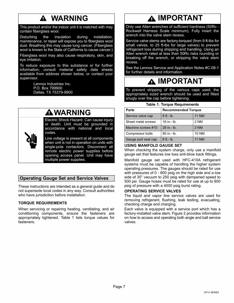
TORQUE REQUIREMENTS
When servicing or repairing heating, ventilating, and airconditioning components, ensure the fasteners areappropriately tightened. Table 1 lists torque values forfasteners.
IMPORTANTOnly use Allen wrenches of sufficient hardness (50Rc −Rockwell Harness Scale minimum). Fully insert thewrench into the valve stem recess.
Service valve stems are factory−torqued (from 9 ft−lbs forsmall valves, to 25 ft−lbs for large valves) to preventrefrigerant loss during shipping and handling. Using anAllen wrench rated at less than 50Rc risks rounding orbreaking off the wrench, or stripping the valve stemrecess.
See the Lennox Service and Application Notes #C−08−1for further details and information.
IMPORTANTTo prevent stripping of the various caps used, theappropriately sized wrench should be used and fittedsnugly over the cap before tightening.
Table 1. Torque Requirements
Parts Recommended Torque
Service valve cap 8 ft.− lb. 11 NM
Sheet metal screws 16 in.− lb. 2 NM
Machine screws #10 28 in.− lb. 3 NM
Compressor bolts 90 in.− lb. 10 NM
Gauge port seal cap 8 ft.− lb. 11 NM
USING MANIFOLD GAUGE SET
When checking the system charge, only use a manifoldgauge set that features low loss anti−blow back fittings.
Manifold gauge set used with HFC−410A refrigerantsystems must be capable of handling the higher systemoperating pressures. The gauges should be rated for usewith pressures of 0 − 800 psig on the high side and a lowside of 30" vacuum to 250 psig with dampened speed to500 psi. Gauge hoses must be rated for use at up to 800psig of pressure with a 4000 psig burst rating.
OPERATING SERVICE VALVES
The liquid and vapor line service valves are used forremoving refrigerant, flushing, leak testing, evacuating,checking charge and charging.
Each valve is equipped with a service port which has afactory−installed valve stem. Figure 2 provides informationon how to access and operating both angle and ball servicevalves.
Page 8
(VALVE STEM SHOWNCLOSED) INSERT HEXWRENCH HERE
SERVICE PORT CORE
SERVICE PORT CAP
ANGLE−TYPE SERVICE VALVE(FRONT−SEATED CLOSED)
SERVICE PORTCORE
TO OUTDOOR UNIT
STEM CAP
(VALVE STEM SHOWN OPEN)INSERT HEX WRENCH HERE
TO INDOORUNIT
ANGLE−TYPE SERVICE VALVE(BACK−SEATED OPENED)
BALL (SHOWNCLOSED)
SERVICE PORTCORE
TO INDOOR UNIT
TO OUTDOORUNIT
TO OPEN ROTATE STEMCOUNTERCLOCKWISE 90°.
TO CLOSE ROTATE STEMCLOCKWISE 90°.
SERVICE PORT
SERVICE PORTCAP
STEM CAP
VALVESTEM
SERVICE VALVES ANGLE AND BALL
Operating Angle Type Service Valve:
1. Remove stem cap with an appropriately sized wrench.
2. Use a service wrench with a hex−head extension (3/16" for liquid line valve sizes and 5/16" for vapor line valve sizes) to backthe stem out counterclockwise as far as it will go.
Operating Ball Type Service Valve:
1. Remove stem cap with an appropriately sized wrench.
2. Use an appropriately sized wrenched to open. To open valve,roate stem counterclockwise 90°. To close rotate stem clockwise90°.
123
4567
8910
11 12
1/12 TURN
To Access Service Port:
A service port cap protects the service port core from contamination andserves as the primary leak seal.
1. Remove service port cap with an appropriately sized wrench.
2. Connect gauge set to service port.
3. When testing is completed, replace service port cap and tighten asfollows:
� With torque wrench: Finger tighten and
torque cap per table 1.
� Without torque wrench: Finger tighten and
use an appropriately sized wrench to turnan additional 1/6 turn clockwise.
123
4567
89101112
1/6 TURN
WHEN SERVICE VALVE IS CLOSED, THE SERVICE PORT IS OPEN
TO THE LINE SET AND INDOOR UNIT.
When service valve is OPEN, the service port isopen to linE set, indoor and outdoor unit.
Reinstall Stem Cap:
Stem cap protects the valve stem from damage and serves as theprimary seal. Replace the stem cap and tighten as follows:
� With Torque Wrench: Finger tighten and
then torque cap per table 1.
� Without Torque Wrench: Finger tight-
en and use an appropriately sizedwrench to turn an additional 1/12 turnclockwise.
NOTE � A label with specific torque requirements may be affixed to the stem cap. If the label is present, use the specified torque.
Figure 2. Angle and Ball Service Valves
Page 9
XP14 SERIES
Recovering Refrigerant from System
MAIN FUSE BOX/BREAKER PANEL
Disconnect all power to the existing outdoor unit at the disconnectswitch or main fuse box/breaker panel.
DISCONNECT POWER CONNECT MANIFOLD GAUGE SET
MANIFOLD GAUGES
RECOVERY MACHINE
CLEAN RECOVERYCYLINDER
OUTDOOR UNIT
HIGHLOW
Connect a gauge set, clean recovery cylinder and a recoverymachine to the service ports of the existing unit. Use theinstructions provided with the recovery machine to make theconnections.
METHOD 1:Us this method if the existing outdoor unit is not equipped with shut−off valves, or if the unit is not operational and you plan to use the existingHCFC−22 to flush the system.
Remove all HCFC−22 refrigerant from the existing system. Check gauges after shutdown to confirm that the entire system is completely void ofrefrigerant.
METHOD 2:Use this method if the existing outdoor unit is equipped with manual shut−off valves, and you plan to use new HCFC−22 refrigerant to flush thesystem.
The following devices could prevent full system charge recovery into the outdoor unit:
� Outdoor unit’s high or low−pressure switches (if applicable) when tripped can cycle the compressor OFF.
� Compressor can stop pumping due to tripped internal pressure relief valve.
� Compressor has internal vacuum protection that is designed to unload the scrolls (compressor stops pumping) when the pressure ratio meets
a certain value or when the suction pressure is as high as 20 psig. (Compressor suction pressures should never be allowed to go into a vacuum.
Prolonged operation at low suction pressures will result in overheating of the scrolls and permanent damage to the scroll tips, drive bearings and
internal seals.)
Once the compressor can not pump down to a lower pressure due to one of the above system conditions, shut off the vapor valve. Turn OFF the
main power to unit and use a recovery machine to recover any refrigerant left in the indoor coil and line set.
Perform the following task:
A Start the existing HCFC−22 system in the cooling mode and close the liquid line valve.
B Use the compressor to pump as much of the existing HCFC−22 refrigerant into the outdoor unit until the outdoor system is full. Turn the outdoor unitmain power OFF and use a recovery machine to remove the remaining refrigerant from the system.
NOTE � It may be necessary to bypass the low pressure switches (if equipped) to ensure complete refrigerant evacuation.
C When the low side system pressures reach 0 psig, close the vapor line valve.
D Check gauges after shutdown to confirm that the valves are not allowing refrigerant to flow back into the low side of the system.
Remove existing HCFC−22 refrigerant using one of the following procedures:
RECOVERING REFRIGERANT
IMPORTANT � Some system configurations may contain higher than normal refrigerant charge due to either large internal coil volumes,and/or long line sets.
1 2
3
DISCONNECTSWITCH
MAIN FUSEBOX/BREAKER
PANEL
Figure 3. Refrigerant Recovery
Page 10
CONTROL PANELACCESS
LOCATION
6 (152)
36 (914)
12 (305)30 (762)
LINE SETCONNECTIONS
24 (610)
48 (1219)
MINIMUM CLEARANCE BETWEENTWO UNITS
CLEARANCE ON ALL SIDES � INCHES (MILLIMETERS)
ACCESS PANEL
MINIMUM CLEARANCEABOVE UNIT
NOTES:
� Clearance to one of the other three
sides must be 36 inches (914mm).
� Clearance to one of the remaining
two sides may be 12 inches(305mm) and the final side may be6 inches (152mm).
Figure 4. Installation Clearances
Unit Placement
CAUTIONIn order to avoid injury, take proper precaution whenlifting heavy objects.
See Unit Dimensions on page 3 for sizing mounting slab,platforms or supports. Refer to figure 4 for mandatoryinstallation clearance requirements.
POSITIONING CONSIDERATIONS
Consider the following when positioning the unit:
� Some localities are adopting sound ordinances based
on the unit’s sound level registered from the adjacent
property, not from the installation property. Install theunit as far as possible from the property line.
� When possible, do not install the unit directly outside
a window. Glass has a very high level of soundtransmission. For proper placement of unit in relationto a window see the provided illustration in figure 5,
detail A.
PLACING UNIT ON SLAB
When installing unit at grade level, the top of the slabshould be high enough above grade so that water fromhigher ground will not collect around the unit. The slabshould have a slope tolerance as described in figure 5,detail B.
NOTE � If necessary for stability, anchor unit to slab as
described in figure 5, detail D.
ELEVATING THE UNIT
Units are outfitted with elongated support feet as illustratedin figure 5, detail C.
If additional elevation is necessary, raise the unit byextending the height of the unit support feet. This may beachieved by using a 2 inch (50.8mm) Schedule 40 femalethreaded adapter.
The specified coupling will fit snuggly into the recessedportion of the feet. Use additional 2 inch (50.8mm)Schedule 40 male threaded adaptors which can bethreaded into the female threaded adaptors to makeadditional adjustments to the level of the unit.
NOTE � Keep the height of extenders short enough to
ensure a sturdy installation. If it is necessary to extend
further, consider a different type of field−fabricated
framework that is sturdy enough for greater heights.
Page 11
XP14 SERIES
LEG DETAIL
BASE
2" (50.8MM) SCH 40FEMALE THREADED
ADAPTER
Concrete slab � use two plastic anchors (holedrill 1/4")
Wood or plastic slab � no plastic anchor (holedrill 1/8")
COIL
BASE PAN
CORNER POST
STABILIZING BRACKET (18 GAUGEMETAL � 2" WIDTH; HEIGHT AS
REQUIRED)
� Slab Side Mounting
#10 1/2" LONG SELF−DRILLINGSHEET METAL SCREWS
#10 1−1/4" LONG HEX HD SCREWAND FLAT WASHER
MINIMUM ONEPER SIDE
Stabilizing bracket (18 gauge metal � 2" (50.8mm) width; height as required); bend to formright angle as exampled below.
FOR EXTRASTABILITY
� Deck Top Mounting
� Elevated Slab Mounting
using Feet Extenders
STABILIZING UNIT ON UNEVEN SURFACES
Install unit level or, if on a slope, maintain slope tolerance of two (2)degrees (or two inches per five feet [50 mm per 1.5 m]) away frombuilding structure.
MOUNTINGSLAB
BUILDINGSTRUCTURE
GROUND LEVEL
� Outside Unit Placement � Slab Mounting at Ground Level
SAME FASTENERS ASSLAB SIDE MOUNTING.
IMPORTANT � To help stabilize an outdoor unit, some installations may require strapping the unit to the pad using brackets and anchorscommonly available in the marketplace.
DETAIL A DETAIL B
DETAIL C
DETAIL D
2" (50.8MM) SCH 40MALE THREADED
ADAPTER
Use additional 2" SCH 40 male threaded adapterswhich can be threaded into the female threadedadapters to make additional adjustments to the level ofthe unit.
TWO 90° ELBOWS INSTALLED IN LINE SET WILLREDUCE LINE SET VIBRATION.
Install unit away from windows.
One bracket per side (minimum). For extra stability, two brackets per side, two inches(51mm) from each corner.
DETAIL E
Figure 5. Placement, Slab Mounting and Stabilizing Unit
Page 12
STABILIZING UNIT ON UNEVEN SURFACES
IMPORTANTUnit Stabilizer Bracket Use (field−provided):
Always use stabilizers when unit is raised above thefactory height. (Elevated units could become unstable ingusty wind conditions).
Stabilizers may be used on factory height units whenmounted on unstable an uneven surface.
With unit positioned at installation site, perform the
following:
1. Remove two side louvered panels to expose the unitbase.
2. Install the brackets as illustrated in figure 5, detail D orE using conventional practices.
3. Replace the panels after installation is complete.
ROOF MOUNTING
Install the unit a minimum of 6 inches (152 mm) above theroof surface to avoid ice build−up around the unit. Locatethe unit above a load bearing wall or area of the roof thatcan adequately support the unit. Consult local codes forrooftop applications.
If unit coil cannot be mounted away from prevailing winterwinds, a wind barrier should be constructed. Size barrier atleast the same height and width as outdoor unit. Mountbarrier 24 inches (610 mm) from the sides of the unit in thedirection of prevailing winds.
NOTICERoof Damage!
This system contains both refrigerant and oil. Somerubber roofing material may absorb oil and cause therubber to swell when it comes into contact with oil. Therubber will then bubble and could cause leaks. Protectthe roof surface to avoid exposure to refrigerant and oilduring service and installation. Failure to follow thisnotice could result in damage to roof surface.
Removing and Installing Panels
IMPORTANTDo not allow panels to hang on unit by top tab. Tab is foralignment and not designed to support weight of panel.
IMPORTANTTo help stabilize an outdoor unit, some installations mayrequire strapping the unit to the pad using brackets andanchors commonly available in the marketplace.
WARNINGTo prevent personal injury, or damage to panels, unit orstructure, be sure to observe the following:
While installing or servicing this unit, carefully stow allremoved panels out of the way, so that the panels will notcause injury to personnel, nor cause damage to objectsor structures nearby, nor will the panels be subjected todamage (e.g., being bent or scratched).
While handling or stowing the panels, consider anyweather conditions, especially windy conditions, thatmay cause panels to be blown around and battered.
Page 13
XP14 SERIES
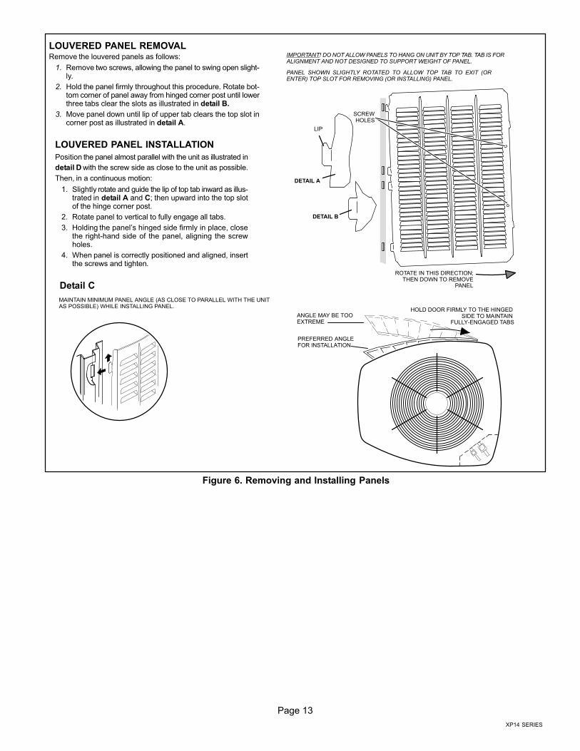
LOUVERED PANEL REMOVALRemove the louvered panels as follows:
1. Remove two screws, allowing the panel to swing open slight-ly.
2. Hold the panel firmly throughout this procedure. Rotate bot-tom corner of panel away from hinged corner post until lowerthree tabs clear the slots as illustrated in detail B.
3. Move panel down until lip of upper tab clears the top slot incorner post as illustrated in detail A.
LOUVERED PANEL INSTALLATION
Position the panel almost parallel with the unit as illustrated in
detail D with the screw side as close to the unit as possible.
Then, in a continuous motion:
1. Slightly rotate and guide the lip of top tab inward as illus-trated in detail A and C; then upward into the top slotof the hinge corner post.
2. Rotate panel to vertical to fully engage all tabs.
3. Holding the panel’s hinged side firmly in place, closethe right−hand side of the panel, aligning the screwholes.
4. When panel is correctly positioned and aligned, insertthe screws and tighten.
DETAIL A
DETAIL B
ROTATE IN THIS DIRECTION;THEN DOWN TO REMOVE
PANEL
SCREWHOLES
LIP
IMPORTANT! DO NOT ALLOW PANELS TO HANG ON UNIT BY TOP TAB. TAB IS FORALIGNMENT AND NOT DESIGNED TO SUPPORT WEIGHT OF PANEL.
PANEL SHOWN SLIGHTLY ROTATED TO ALLOW TOP TAB TO EXIT (ORENTER) TOP SLOT FOR REMOVING (OR INSTALLING) PANEL.
MAINTAIN MINIMUM PANEL ANGLE (AS CLOSE TO PARALLEL WITH THE UNITAS POSSIBLE) WHILE INSTALLING PANEL.
PREFERRED ANGLEFOR INSTALLATION
ANGLE MAY BE TOOEXTREME
HOLD DOOR FIRMLY TO THE HINGED SIDE TO MAINTAIN
FULLY−ENGAGED TABS
Detail C
Figure 6. Removing and Installing Panels
Page 14
New or Replacement Line Set
REFRIGERANT LINE SET
This section provides information on installation orreplacement of existing line set. If new or replacement lineset is not being installed then proceed to BrazingConnections on page 16.
IMPORTANTLennox highly recommends changing line set whenconverting the existing system from HCFC−22 toHFC−410A. If that is not possible and the line set is theproper size as reference in table 2, use the procedureoutlined under Flushing the System on page 13.
If refrigerant lines are routed through a wall, then seal andisolate the opening so vibration is not transmitted to thebuilding. Pay close attention to line set isolation duringinstallation of any HVAC system. When properly isolatedfrom building structures (walls, ceilings. floors), therefrigerant lines will not create unnecessary vibration andsubsequent sounds. See figure 7 for recommendedinstallation practices. Also, consider the following whenplacing and installing a high−efficiency outdoor unit.
Liquid lines that meter the refrigerant, such as RFC1 liquidlines, must not be used in this application. Existing line setof proper size as listed in table 2 may be reused. If systemwas previously charged with HCFC−22 refrigerant, thenexisting line set must be flushed (see Flushing the Systemon page 19).
Field refrigerant piping consists of liquid and vapor linesfrom the outdoor unit to the indoor unit coil (brazeconnections). Use Lennox L15 (sweat, non−flare) seriesline set, or field−fabricated refrigerant line sizes as listed intable 2.
Table 2. Refrigerant Line Set � Inches (mm)
Model
Valve FieldConnections
Recommended Line Set
LiquidLine
VaporLine
LiquidLine
VaporLine
L15Line Sets
−018−024−030
3/8 in.(10 mm)
3/4 in(19 mm)
3/8 in.(10mm)
3/4 in(19 mm)
L15−4115 ft. − 50 ft.(4.6 m − 15 m)
−036−042−048
3/8 in.(10 mm)
7/8 in(22 mm)
3/8 in.(10mm)
7/8 in(22 mm)
L15−6515 ft. − 50 ft.(4.6 m − 15 m)
−0603/8 in.(10 mm)
1−1/8 in.(29 mm)
3/8 in.(10mm)
1−1/8 in.(29 mm)
FieldFabricated
NOTE � When installing refrigerant lines longer than 50
feet, see the Lennox Refrigerant Piping Design and
Fabrication Guidelines, CORP. 9351−L9, or contact
Lennox Technical Support Product Applications for
assistance.
To obtain the correct information from Lennox, be sure tocommunicate the following information:
� Model (XP14) and size of unit (e.g. −036).
� Line set diameters for the unit being installed as listed
in table 2 and total length of installation.
� Number of elbows vertical rise or drop in the piping.
The compressor is charged with sufficient Polyol ester oilfor line set lengths up to 50 feet. Recommend adding oil tosystem based on the amount of refrigerant charge in thesystem. No need to add oil in system with 20 pounds ofrefrigerant or less. For systems over 20 pounds − add oneounce of every five pounds of refrigerant.
Recommended topping−off POE oils are Mobil EALARCTIC 22 CC or ICI EMKARATE� RL32CF.
WARNINGPolyol Ester (POE) oils used with HFC−410Arefrigerant absorb moisture very quickly. It is veryimportant that the refrigerant system be kept closedas much as possible. DO NOT remove line set capsor service valve stub caps until you are ready to makeconnections.
IMPORTANTMineral oils are not compatible with HFC−410A. If oilmust be added, it must be a Polyol Ester oil.
Page 15
XP14 SERIES
ANCHORED HEAVY NYLONWIRE TIE OR AUTOMOTIVE
MUFFLER-TYPE HANGER
STRAP LIQUID LINE TOVAPOR LINE
WALLSTUD
LIQUID LINE
NON−CORROSIVEMETAL SLEEVE
VAPOR LINE − WRAPPEDIN ARMAFLEX
AUTOMOTIVEMUFFLER-TYPE HANGER
REFRIGERANT LINE SET � TRANSITIONFROM VERTICAL TO HORIZONTAL
Line Set Isolation � The following illustrations are examples of proper refrigerant line set isolation:
STRAPPINGMATERIAL (AROUND
VAPOR LINE ONLY)
TAPE ORWIRE TIE
WIRE TIE (AROUNDVAPOR LINE ONLY)
FLOOR JOIST ORROOF RAFTER
TAPE ORWIRE TIE
To hang line set from joist or rafter, use either metal strapping materialor anchored heavy nylon wire ties.
8 FEET (2.43 METERS)
STRAP THE VAPOR LINE TO THE JOISTOR RAFTER AT 8 FEET (2.43 METERS)INTERVALS THEN STRAP THE LIQUIDLINE TO THE VAPOR LINE.
FLOOR JOIST OR
ROOF RAFTER
REFRIGERANT LINE SET � INSTALLING HORIZONTAL RUNS
NOTE � Similar installation practices should be used if line set isto be installed on exterior of outside wall.
PVCPIPE
FIBERGLASSINSULATION
CAULK
OUTSIDEWALL
VAPOR LINE WRAPPEDWITH ARMAFLEX
LIQUIDLINE
OUTSIDE WALL LIQUID LINEVAPOR LINE
WOOD BLOCKBETWEEN STUDS
STRAP
WOOD BLOCK
STRAP
SLEEVE
WIRE TIE
WIRE TIE
WIRE TIE
INSIDE WALL
REFRIGERANT LINE SET � INSTALLINGVERTICAL RUNS (NEW CONSTRUCTION SHOWN)
NOTE � Insulate liquid line when it is routed through areas where thesurrounding ambient temperature could become higher than thetemperature of the liquid line or when pressure drop is equal to or greaterthan 20 psig.
NON−CORROSIVEMETAL SLEEVE
NON−CORROSIVEMETAL SLEEVE
8 FEET (2.43 METERS)
Figure 7. Line Set Installation
Page 16
Brazing Connections
Use the procedures outline in figures 8 and 9 for brazingline set connections to service valves.
WARNINGDanger of fire. Bleeding the refrigerantcharge from only the high side may resultin pressurization of the low side shell andsuction tubing. Application of a brazingtorch to a pressurized system may resultin ignition of the refrigerant and oilmixture − Check the high and lowpressures before applying heat.
WARNINGWhen using a high pressure gas such asdry nitrogen to pressurize a refrigerationor air conditioning system, use aregulator that can control the pressuredown to 1 or 2 psig (6.9 to 13.8 kPa).
CAUTIONBrazing alloys and flux contain materials which arehazardous to your health.
Avoid breathing vapors or fumes from brazingoperations. Perform operations only in well−ventilatedareas.
Wear gloves and protective goggles or face shield toprotect against burns.
Wash hands with soap and water after handling brazingalloys and flux.
IMPORTANTConnect gauge set low pressure side to vapor lineservice valve and repeat procedure starting atparagraph 4 for brazing the liquid line to service portvalve.
IMPORTANTAllow braze joint to cool before removing the wet ragfrom the service valve. Temperatures above 250ºF candamage valve seals.
IMPORTANTUse silver alloy brazing rods with 5% minimum silveralloy for copper−to−copper brazing. Use 45% minimumalloy for copper−to−brass and copper−to−steel brazing.
WARNINGFire, Explosion and Personal SafetyHazard.
Failure to follow this warning couldresult in damage, personal injury ordeath.
Never use oxygen to pressurize orpurge refrigeration lines. Oxygen,when exposed to a spark or openflame, can cause fire and/or an ex-plosion, that could result in propertydamage, personal injury or death.
Page 17
XP14 SERIES
ATTACH THE MANIFOLD GAUGE SET FOR BRAZING LIQUID AND SUCTION / VAPOR LINE SERVICEVALVES
OUTDOORUNIT
LIQUID LINE
VAPOR LINE
LIQUID LINE SERVICEVALVE
SUCTION /VAPOR LINE
SERVICEVALVE
ATTACHGAUGES
INDOORUNIT
SUCTION / VAPOR SERVICE PORT MUST BEOPEN TO ALLOW EXIT POINT FOR NITROGEN
A Connect gauge set low pressure side toliquid line service valve (service port).
B Connect gauge set center port to bottle ofnitrogen with regulator.
C Remove core from valve in suction / vaporline service port to allow nitrogen to escape.
NITROGEN
HIGHLOWUSE REGULATOR TO FLOWNITROGEN AT 1 TO 2 PSIG.
B
A
C
WHEN BRAZING LINE SET TOSERVICE VALVES, POINT FLAME
AWAY FROM SERVICE VALVE.
Flow regulated nitrogen (at 1 to 2 psig) through the low−side refrigeration gauge set into the liquid line service port valve, and out of the suction /vapor line service port valve.
CUT AND DEBUR CAP AND CORE REMOVAL
Cut ends of the refrigerant lines square (free from nicks or dents)and debur the ends. The pipe must remain round. Do not crimp endof the line.
Remove service cap and core fromboth the suction / vapor and liquid lineservice ports.
1 2
LIQUID LINE SERVICEVALVE
SERVICEPORTCORE
SERVICE PORTCAP
SERVICEPORTCORE
SERVICEPORT CAP
CUT AND DEBUR
LINE SET SIZE MATCHESSERVICE VALVE CONNECTION
COPPER TUBESTUB
SERVICE VALVECONNECTION
REFRIGERANT LINE
DO NOT CRIMP SERVICE VALVECONNECTOR WHEN PIPE IS
SMALLER THAN CONNECTION
REDUCER
3
SUCTION / VAPOR LINESERVICE VALVE
LINE SET SIZE IS SMALLERTHAN CONNECTION
Figure 8. Brazing Procedures
Page 18
WHEN BRAZING LINE SET TOSERVICE VALVES, POINT FLAME
AWAY FROM SERVICE VALVE.
LIQUID LINE SERVICE VALVE
LIQUID LINE
BRAZE LINE SET
Wrap both service valves with water saturated cloths as illustrated here and as mentioned in step 4, before brazing to line set. Watersaturated cloths must remain water saturated throughout the brazing and cool−down process.
WATER SATURATEDCLOTH
IMPORTANT � Allow braze joint to cool. Applyadditional water saturated cloths to help cool brazedjoint. Do not remove water saturated cloths until pipinghas cooled. Temperatures above 250ºF will damagevalve seals.
6
SUCTION / VAPOR LINE
WATER SATURATEDCLOTH
SUCTION / VAPOR LINESERVICE VALVE
After all connections have been brazed, disconnect manifold gauge set from service ports. Apply additional water saturated cloths to bothservices valves to cool piping. Once piping is cool, remove all water saturated cloths. Refer to the unit installation instructions for the next stepin preparing the unit.
WHEN BRAZING LINE SET TOSERVICE VALVES, POINT FLAME
AWAY FROM SERVICE VALVE.
PREPARATION FOR NEXT STEP7
WARNING
1. FIRE, PERSONAL INJURY, OR PROPERTYDAMAGE will result if you do not wrap a watersaturated cloth around both liquid and suction lineservice valve bodies and copper tube stub whilebrazing in the line set! The braze, when complete,must be quenched with water to absorb any residualheat.
2. Do not open service valves until refrigerant lines andindoor coil have been leak−tested and evacuated.Refer to procedures provided in this supplement.
WRAP SERVICE VALVES
To help protect service valve seals during brazing, wrap water saturated cloths around service valve bodies and copper tube stubs. Useadditional water saturated cloths underneath the valve body to protect the base paint.
4FLOW NITROGEN
Flow regulated nitrogen (at 1 to 2 psig) through the refrigeration gauge set into the valve stem port connection on the liquid service valve andout of the suction / vapor valve stem port. See steps 3A, 3B and 3C on manifold gauge set connections
5
Figure 9. Brazing Procedures (continued)
Page 19
XP14 SERIES
Flushing Line Set and Indoor Coil
SENSINGLINE
TEFLON® RING
FIXED ORIFICE
BRASS NUT
LIQUID LINE ASSEMBLY(INCLUDES STRAINER)
LIQUID LINE ORIFICE HOUSING
DISTRIBUTOR TUBES
DISTRIBUTORASSEMBLY
REMOVE AND DISCARD
WHITE TEFLON® SEAL(IF PRESENT)
A On fully cased coils, remove the coil access and plumbing panels.
B Remove any shipping clamps holding the liquid line and distributor as-sembly.
C Using two wrenches, disconnect liquid line from liquid line orifice hous-ing. Take care not to twist or damage distributor tubes during this pro-cess.
D Remove and discard fixed orifice, valve stem assembly if present andTeflon® washer as illustrated above.
E Use a field−provided fitting to temporary reconnect the liquid line to theindoor unit’s liquid line orifice housing.
A On fully cased coils, remove the coil access and plumbing panels.
B Remove any shipping clamps holding the liquid line and distributorassembly.
C Disconnect the equalizer line from the check expansion valveequalizer line fitting on the vapor line.
D Remove the vapor line sensing bulb.
E Disconnect the liquid line from the check expansion valve at the liquidline assembly.
F Disconnect the check expansion valve from the liquid line orificehousing. Take care not to twist or damage distributor tubes during thisprocess.
G Remove and discard check expansion valve and the two Teflon® rings.
H Use a field−provided fitting to temporary reconnect the liquid line to theindoor unit’s liquid line orifice housing.
LOW HIGH
EXISTINGINDOOR
UNIT
GAUGEMANIFOLD
INVERTED HCFC−22CYLINDER CONTAINSCLEAN HCFC−22 TO BEUSED FOR FLUSHING.
LIQUID LINE SERVICEVALVE
INLET
DISCHARGE
TANKRETURN
CLOSEDOPENED
RECOVERYCYLINDER
RECOVERY MACHINE
NEWOUTDOOR
UNIT
VAPOR LINESERVICE VALVE
VA
PO
R
LIQ
UID
1
A Inverted HCFC−22 cylinder with clean refrigerant to the vapor servicevalve.
B HCFC−22 gauge set (low side) to the liquid line valve.
C HCFC−22 gauge set center port to inlet on the recovery machine with anempty recovery tank to the gauge set.
D Connect recovery tank to recovery machines per machine instructions.
CONNECT GAUGES AND EQUIPMENT FORFLUSHING PROCEDURE
A
B
CD
B
OR
FLUSHING LINE SET
A Set the recovery machine for liquid recovery and start therecovery machine. Open the gauge set valves to allow therecovery machine to pull a vacuum on the existing system lineset and indoor unit coil.
B Invert the cylinder of clean HCFC−22 and open its valve to allowliquid refrigerant to flow into the system through the vapor linevalve. Allow the refrigerant to pass from the cylinder and throughthe line set and the indoor unit coil before it enters the recoverymachine.
C After all of the liquid refrigerant has been recovered, switch therecovery machine to vapor recovery so that all of the HCFC−22vapor is recovered. Allow the recovery machine to pull down to 0the system.
D Close the valve on the inverted HCFC−22 drum and the gaugeset valves. Pump the remaining refrigerant out of the recoverymachine and turn the machine off.
The line set and indoor unit coil must be flushed with at least thesame amount of clean refrigerant that previously charged thesystem. Check the charge in the flushing cylinder beforeproceeding.
1A
2
3
1B
Figure 10. Installing Indoor Expansion Valve
Page 20
Installing Indoor Metering Device
This outdoor unit is designed for use in systems that usecheck expansion valve metering devices at the indoor coil.
See the Lennox XP14 Engineering Handbook forapproved expansion valve kit match−ups. The expansionvalve unit can be installed internal or external to the indoor
coil. In applications where an uncased coil is beinginstalled in a field−provided plenum, install the expansionvalve in a manner that will provide access for field servicingof the expansion valve. Refer to below illustration forreference during installation of expansion valve unit.
A Attach the vapor line sensing bulb in the properorientation as illustrated to the right using the clamp andscrews provided.
NOTE � Confirm proper thermal contact between vapor lineand expansion bulb before insulating the sensing bulb onceinstalled.
B Connect the equalizer line from the expansion valve tothe equalizer vapor port on the vapor line. Finger tightenthe flare nut plus 1/8 turn (7 ft−lbs) as illustrated below.
TWO PIECEPATCH PLATE
(UNCASEDCOIL ONLY)
VAPORLINE
LIQUID LINEORIFICE
HOUSINGDISTRIBUTOR
TUBES
LIQUID LINE
MALE EQUALIZER LINEFITTING (SEE
EQUALIZER LINEINSTALLATION FORFURTHER DETAILS)
SENSINGLINE
EQUALIZERLINE
CHECKEXPANSION
VALVE
TEFLON®
RING
(Uncased Coil Shown)
Sensing bulb insulation is required ifmounted external to the coil casing. sensingbulb installation for bulb positioning.
STUBEND
TEFLON®
RING
LIQUID LINEASSEMBLY WITH
BRASS NUT
DISTRIBUTORASSEMBLY
A Remove the field−provided fitting that temporaryreconnected the liquid line to the indoor unit’s distributorassembly.
B Install one of the provided Teflon® rings around thestubbed end of the expansion valve and lightly lubricatethe connector threads and expose surface of the Teflon®
ring with refrigerant oil.
C Attach the stubbed end of the expansion valve to theliquid line orifice housing. Finger tighten and use anappropriately sized wrench to turn an additional 1/2 turnclockwise as illustrated in the figure above, or 20 ft−lb.
D Place the remaining Teflon® washer around the otherend of the expansion valve. Lightly lubricate connectorthreads and expose surface of the Teflon® ring withrefrigerant oil.
E Attach the liquid line assembly to the expansion valve.Finger tighten and use an appropriately sized wrench toturn an additional 1/2 turn clockwise as illustrated in thefigure above or 20 ft−lb.
ON 7/8" AND LARGER LINES,MOUNT SENSING BULB ATEITHER THE 4 OR 8 O’CLOCKPOSITION. NEVER MOUNT ONBOTTOM OF LINE.
12
ON LINES SMALLER THAN7/8", MOUNT SENSINGBULB AT EITHER THE 3 OR9 O’CLOCK POSITION.
12
BULB
VAPOR LINE
VAPOR LINE
NOTE � NEVER MOUNT ON BOTTOM OF LINE.
BULB
BULBBULB
VAPOR LINE
FLARE NUT
COPPER FLARESEAL BONNET
MALE BRASS EQUALIZERLINE FITTING
FLARE SEAL CAP
OR
123
4567
8910
11 12
1/2 Turn
SENSING BULB INSTALLATION
EQUALIZER LINE INSTALLATION
123
4567
8910
11 12
1/8 Turn
A Remove and discard either the flare seal cap or flare nutwith copper flare seal bonnet from the equalizer line porton the vapor line as illustrated in the figure to the right.
B Remove and discard either the flare seal cap or flare nutwith copper flare seal bonnet from the equalizer line port onthe vapor line as illustrated in the figure to the right.
INDOOR EXPANSION VALVE INSTALLATION
Figure 11. Installing Indoor Expansion Valve
Page 21
XP14 SERIES
IMPORTANTThe Environmental Protection Agency (EPA) prohibitsthe intentional venting of HFC refrigerants duringmaintenance, service, repair and disposal of appliance.Approved methods of recovery, recycling or reclaimingmust be followed.
IMPORTANTIf this unit is being matched with an approved line setor indoor unit coil which was previously charged withmineral oil, or if it is being matched with a coil whichwas manufactured before January of 1999, the coiland line set must be flushed prior to installation. Takecare to empty all existing traps. Polyol ester (POE) oilsare used in Lennox units charged with HFC−410Arefrigerant. Residual mineral oil can act as aninsulator, preventing proper heat transfer. It can alsoclog the expansion device, and reduce the systemperformance and capacity.Failure to properly flush the system per theinstructions below will void the warranty.
Leak Test Line Set and Indoor Coil
WARNINGWhen using a high pressure gas such asdry nitrogen to pressurize a refrigerationor air conditioning system, use aregulator that can control the pressuredown to 1 or 2 psig (6.9 to 13.8 kPa).
IMPORTANTLeak detector must be capable of sensing HFCrefrigerant.
WARNINGRefrigerant can be harmful if it is inhaled. Refrigerantmust be used and recovered responsibly.
Failure to follow this warning may result in personal injuryor death.
TO VAPORSERVICE VALVE
HFC−410A
MANIFOLD GAUGE SET
OUTDOOR UNIT
HIGHLOW
NITROGEN
A With both manifold valves closed, connect the cylinder of HFC−410A refrigerant to the center port of the manifold gauge set. Open the valveon the HFC−410A cylinder (vapor only).
B Open the high pressure side of the manifold to allow HFC−410A into the line set and indoor unit. Weigh in a trace amount of HFC−410A. [Atrace amount is a maximum of two ounces (57 g) refrigerant or three pounds (31 kPa) pressure]. Close the valve on the HFC−410A cylinderand the valve on the high pressure side of the manifold gauge set. Disconnect the HFC−410A cylinder.
C Connect a cylinder of dry nitrogen with a pressure regulating valve to the center port of the manifold gauge set.
D Adjust dry nitrogen pressure to 150 psig (1034 kPa). Open the valve on the high side of the manifold gauge set in order to pressurize the line setand the indoor unit.
E After a few minutes, open one of the service valve ports and verify that the refrigerant added to the system earlier is measurable with a leakdetector.
F After leak testing disconnect gauges from service ports.
After the line set has been connected to the indoor and outdoor units, check the line set connections and indoor unit for leaks. Use thefollowing procedure to test for leaks:
A Connect an HFC−410A manifold gauge set high pressurehose to the vapor valve service port.
NOTE � Normally, the high pressure hose is connected tothe liquid line port. However, connecting it to the vapor portbetter protects the manifold gauge set from high pressuredamage.
B With both manifold valves closed, connect the cylinder ofHFC−410A refrigerant to the center port of the manifold gaugeset.
NOTE � Later in the procedure,the HFC−410A container will bereplaced by the nitrogencontainer.
1CONNECT GAUGE SET
2TEST FOR LEAKS
AB
Figure 12. Leak Test
Page 22
Evacuating Line Set and Indoor Coil
A Open both manifold valves and start the vacuum pump.
B Evacuate the line set and indoor unit to an absolute pressure of 23,000 microns (29.01 inches of mercury).
NOTE � During the early stages of evacuation, it is desirable to close the manifold gauge valve at least once. A rapid rise in pressure
indicates a relatively large leak. If this occurs, repeat the leak testing procedure.
NOTE � The term absolute pressure means the total actual pressure within a given volume or system, above the absolute zero ofpressure. Absolute pressure in a vacuum is equal to atmospheric pressure minus vacuum pressure.
C When the absolute pressure reaches 23,000 microns (29.01 inches of mercury), perform the following:
� Close manifold gauge valves
� Close valve on vacuum pump
� Turn off vacuum pump
� Disconnect manifold gauge center port hose from vacuum pump
� Attach manifold center port hose to a dry nitrogen cylinder with pressure regulator set to 150 psig (1034 kPa) and purge the hose.
� Open manifold gauge valves to break the vacuum in the line set and indoor unit.
� Close manifold gauge valves.
D Shut off the dry nitrogen cylinder and remove the manifold gauge hose from the cylinder. Open the manifold gauge valves to release thedry nitrogen from the line set and indoor unit.
E Reconnect the manifold gauge to the vacuum pump, turn the pump on, and continue to evacuate the line set and indoor unit until theabsolute pressure does not rise above 500 microns (29.9 inches of mercury) within a 20−minute period after shutting off the vacuum pumpand closing the manifold gauge valves.
F When the absolute pressure requirement above has been met, disconnect the manifold hose from the vacuum pump and connect it to anupright cylinder of HFC−410A refrigerant. Open the manifold gauge valve 1 to 2 psig in order to release the vacuum in the line set andindoor unit.
G Perform the following:
OUTDOOR
UNIT
TO VAPORSERVICE VALVE
TO LIQUID LINESERVICE VALVE
MICRONGAUGE
VACUUM PUMP
A34000 1/4 SAE TEE WITHSWIVEL COUPLER
500
MANIFOLDGAUGE SET
HFC−410A
RECOMMENDMINIMUM 3/8" HOSE
AConnect low side of manifold gauge setwith 1/4 SAE in−line tee to vapor lineservice valve
BConnect high side of manifold gaugeset to liquid line service valve
CConnect micron gauge availableconnector on the 1/4 SAE in−line tee.
DConnect the vacuum pump (withvacuum gauge) to the center port of themanifold gauge set. The center portline will be used later for both theHFC−410A and nitrogen containers.
HIGHLOW
12
34
56
78
910
11 12
1/6 TURN
NITROGEN
1CONNECT GAUGE SET
A
B
C
D
2EVACUATE THE SYSTEM
NOTE � Remove cores from service valves (if not already done).
� Close manifold gauge valves.
� Shut off HFC−410A cylinder.
� Reinstall service valve cores by removing manifold hose from service valve. Quickly install cores with core
tool while maintaining a positive system pressure.
� Replace stem caps and secure finger tight, then tighten an additional one−sixth (1/6) of a turn as illustrated.
Figure 13. Evacuating System
Page 23
XP14 SERIES
IMPORTANTUse a thermocouple or thermistor electronic vacuumgauge that is calibrated in microns. Use an instrumentcapable of accurately measuring down to 50 microns.
WARNINGDanger of Equipment Damage. Avoid deep vacuumoperation. Do not use compressors to evacuate asystem. Extremely low vacuums can cause internalarcing and compressor failure. Damage caused bydeep vacuum operation will void warranty.
Evacuating the system of non−condensables is critical forproper operation of the unit. Non−condensables aredefined as any gas that will not condense under
temperatures and pressures present during operation ofan air conditioning system. Non−condensables and watersuction combine with refrigerant to produce substancesthat corrode copper piping and compressor parts.
Electrical
In the U.S.A., wiring must conform with current local codesand the current National Electric Code (NEC). In Canada,wiring must conform with current local codes and the currentCanadian Electrical Code (CEC).
Refer to the furnace or air handler installation instructionsfor additional wiring application diagrams and refer to unitnameplate for minimum circuit ampacity and maximumovercurrent protection size.
24VAC TRANSFORMER
Use the transformer provided with the furnace or airhandler for low-voltage control power (24VAC − 40 VAminimum)
Refer to the unit nameplate for minimum circuit ampacity, andmaximum fuse or circuit breaker (HACR per NEC). Install powerwiring and properly sized disconnect switch.
NOTE � Units are approved for use only with copper conductors.Ground unit at disconnect switch or to an earth ground.
SIZE CIRCUIT AND INSTALL DISCONNECTSWITCH1
NOTE � 24VAC, Class II circuit connections are made in the controlpanel.
Install room thermostat (ordered separately) on an inside wallapproximately in the center of the conditioned area and 5 feet(1.5m) from the floor. It should not be installed on an outside wallor where it can be affected by sunlight or drafts.
THERMOSTAT
5 FEET(1.5M)
INSTALL THERMOSTAT
2
DISCONNECTSWITCH
MAIN FUSEBOX/BREAKER
PANEL
A Run 24VAC control wires through cutout with grommet.
B Run 24VAC control wires through wire tie.
C Make 24VAC control wire connections defrost control terminalstrip.
D Tighten wire tie to security 24V control wiring.
HIGH VOLTAGE FIELD WIRING
LOW VOLTAGE (24V) FIELD WIRING
FACTORY WIRING
NOTE − FOR PROPER VOLTAGES, SELECT THERMOSTAT WIRE (CONTROL WIRES)GAUGE PER TABLE ABOVE.
WIRE RUN LENGTH AWG# INSULATION TYPE
LESS THAN 100’ (30 METERS) 18 TEMPERATURE RATING
MORE THAN 100’ (30 METERS) 16 35ºC MINIMUM.
TERMINAL STRIP
UNIT LOW VOLTAGE CONNECTIONS
NOTE − DO NOT BUNDLE ANY EXCESS 24VAC CONTROL WIRES INSIDE CONTROLBOX.
NOTE − WIRE TIE PROVIDES LOW VOLTAGE WIRE STRAIN RELIEF AND TO MAINTAINSEPARATION OF FIELD INSTALLED LOW AND HIGH VOLTAGE CIRCUITS.
3
A
B
C
D
Page 24
Servicing Units Void of Charge
If the outdoor unit is void of refrigerant, clean the systemusing the procedure described below.
1. Leak check system using procedure outlined on page21.
2. Evacuate the system using procedure outlined onpage 22.
3. Use nitrogen to break the vacuum and install a newfilter drier in the system.
4. Evacuate the system again using procedure outlinedon page 22.
5. Weigh in refrigerant using procedure outlined in figure16.
6. Monitor the system to determine the amount ofmoisture remaining in the oil. It may be necessary toreplace the filter drier several times to achieve therequired dryness level. If system dryness is notverified, the compressor will fail in the future.
Unit Start−Up
IMPORTANTIf unit is equipped with a crankcase heater, it should beenergized 24 hours before unit start−up to preventcompressor damage as a result of slugging.
1. Rotate fan to check for binding.
2. Inspect all factory− and field−installed wiring for looseconnections.
3. After evacuation is complete, open both the liquid andvapor line service valves to release the refrigerantcharge contained in outdoor unit into the system.
4. Replace the stem caps and tighten to the value listedin table 1.
5. Check voltage supply at the disconnect switch. Thevoltage must be within the range listed on the unit’snameplate. If not, do not start the equipment until youhave consulted with the power company and thevoltage condition has been corrected.
6. Set the thermostat for a cooling demand. Turn onpower to the indoor indoor unit and close the outdoorunit disconnect switch to start the unit.
7. Recheck voltage while the unit is running. Power mustbe within range shown on the nameplate.
8. Check system for sufficient refrigerant by using theprocedures listed under System Charge.
System Refrigerant
This section outlines procedures for:
1. Connecting gauge set for testing and charging;
2. Checking and adjusting indoor airflow;
3. Adding or removing refrigerant.
TO LIQUIDLINE SERVICE
VALVETEMPERATURESENSOR
DIGITAL SCALE
REFRIGERANT TANK
TEMPERATURE SENSOR(LIQUID LINE)
MANIFOLD GAUGE SET
A Close manifold gauge set valves and connect the center hose to a cylinder of HFC−410A. Set for liquid phase charging.
B Connect the manifold gauge set’s low pressure side to the true suction port. See figure 1 for approximate location of the true suction port.
C Connect the manifold gauge set’s high pressure side to the liquid line service port.
D Position temperature sensor on liquid line near liquid line service port.
OUTDOOR UNIT
CHARGE INLIQUID PHASE
CONNECTIONS FOR TESTING AND CHARGING
GAUGE SET
A
CD
LOW HIGH
B
INSIDE OUTDOOR UNIT
TRUE SUCTION PORTCONNECTION
Figure 14. Gauge Set Setup and Connections
Page 25
XP14 SERIES
ADDING OR REMOVING REFRIGERANT
This system uses HFC−410A refrigerant which operates at much higher pressures than HCFC−22. The pre−installed liquidline filter drier is approved for use with HFC−410A only. Do not replace it with components designed for use with HCFC−22.This unit is NOT approved for use with coils which use capillary tubes or fixed orifices as a refrigerant metering device.
Check airflow using the Delta−T (DT) process using the illustration in figure 15.
Cº TDrop – DT = ºF ACTION
53º 19 – 15 = 4 Increase the airflow
58º 14 – 15 = −1 (within +3º range) no change
62º 10 – 15 = −5 Decrease the airflow
DT
80 24 24 24 23 23 22 22 22 20 19 18 17 16 15
78 23 23 23 22 22 21 21 20 19 18 17 16 15 14
76 22 22 22 21 21 20 19 19 18 17 16 15 14 13
74 21 21 21 20 19 19 18 17 16 16 15 14 13 12
72 20 20 19 18 17 17 16 15 15 14 13 12 11 10
70 19 19 18 18 17 17 16 15 15 14 13 12 11 10
57 58 59 60 61 62 63 64 65 66 67 68 69 70
Temperature of airentering indoorcoil ºF
INDOOR COIL
DRY BULB
DRYBULB
WET BULB
B
TDrop
19º
A
Dry
−bu
lb
Wet−bulb ºF
A
72º
B
64º
C
53º
air flowair flow
All temperatures are expressed in ºF
1. Determine the desired DT � Measure entering air temperature using dry bulb (A) and wet bulb (B). DTis the intersecting value of A and B in the table (see triangle).
2. Find temperature drop across coil � Measure the coil’s dry bulb entering and leaving air temperatures(A and C). Temperature Drop Formula: (TDrop) = A minus C.
3. Determine if fan needs adjustment � If the difference between the measured TDrop and the desiredDT (TDrop–DT) is within +3º, no adjustment is needed. See example below:
4. Adjust the fan speed � See indoor unit instructions to increase/decrease fan speed.
Assume DT = 15 and A temp. = 72º, these C temperatures would necessitate stated actions:
AIRFLOW
Use the following procedure to adjust for optimal air flow across the indoor coil:
INDOOR COIL
Changing air flow affects all temperatures; rechecktemperatures to confirm that the temperature dropand DT are within +3º.
Figure 15. Checking Indoor Airflow over Evaporator Coil using Delta−T Chart
Page 26
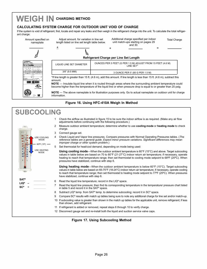
WEIGH IN
LIQUID LINE SET DIAMETEROUNCES PER 5 FEET (G PER 1.5 M) ADJUST FROM 15 FEET (4.6 M)
LINE SET*
3/8" (9.5 MM) 3 OUNCE PER 5’ (85 G PER 1.5 M)
*If line length is greater than 15 ft. (4.6 m), add this amount. If line length is less than 15 ft. (4.6 m), subtract thisamount.
Refrigerant Charge per Line Set Length
NOTE � The above nameplate is for illustration purposes only. Go to actual nameplate on outdoor unit for chargeinformation.
CHARGING METHOD
NOTE � Insulate liquid line when it is routed through areas where the surrounding ambient temperature couldbecome higher than the temperature of the liquid line or when pressure drop is equal to or greater than 20 psig.
CALCULATING SYSTEM CHARGE FOR OUTDOOR UNIT VOID OF CHARGE
If the system is void of refrigerant, first, locate and repair any leaks and then weigh in the refrigerant charge into the unit. To calculate the total refriger-ant charge:
Amount specified onnameplate
Adjust amount. for variation in line setlength listed on line set length table below.
Additional charge specified per indoorunit match−ups starting on pages 29
and 30.
Total Charge
+ + =
Figure 16. Using HFC−410A Weigh In Method
1 Check the airflow as illustrated in figure 15 to be sure the indoor airflow is as required. (Make any air flowadjustments before continuing with the following procedure.)
2 Measure outdoor ambient temperature; determine whether to use cooling mode or heating mode to checkcharge.
3 Connect gauge set.
4 Check Liquid and Vapor line pressures. Compare pressures with Normal Operating Pressures tables. (Thereference tables are a general guide. Expect minor pressure variations. Significant differences may meanimproper charge or other system problem.)
5 Set thermostat for heat/cool demand, depending on mode being used:
Using cooling mode�When the outdoor ambient temperature is 60°F (15°C) and above. Target subcoolingvalues in table below are based on 70 to 80°F (21−27°C) indoor return air temperature; if necessary, operateheating to reach that temperature range; then set thermostat to cooling mode setpoint to 68ºF (20ºC). Whenpressures have stabilized, continue with step 6.
Using heating mode�When the outdoor ambient temperature is below 60°F (15°C). Target subcoolingvalues in table below are based on 65−75°F (18−24°C) indoor return air temperature; if necessary, operate coolingto reach that temperature range; then set thermostat to heating mode setpoint to 77ºF (25ºC). When pressureshave stabilized, continue with step 6.
6 Read the liquid line temperature; record in the LIQº space.
7 Read the liquid line pressure; then find its corresponding temperature in the temperature/ pressure chart listedin table 5 and record it in the SATº space.
8 Subtract LIQº temp. from SATº temp. to determine subcooling; record it in SCº space.
9 Compare SCº results with match up tables being sure to note any additional charge for line set and/or match−up.
10 If subcooling value is greater than shown in the match up tables for the applicable unit, remove refrigerant; if lessthan shown, add refrigerant.
11 If refrigerant is added or removed, repeat steps 6 through 10 to verify charge.
12 Disconnect gauge set and re−install both the liquid and suction service valve caps.
USE COOLINGMODE
USE HEATINGMODE
60ºF (15º)
SATº
LIQº –
SCº =
SUBCOOLING
Figure 17. Using Subcooling Method
Page 27
XP14 SERIES
Table 3. Unit Indoor Matchups for Subcooling (All Models)
INDOOR MATCHUPS
TargetSubcooling
Heating�Cooling(+5ºF)���(+1ºF)
*Addcharge
INDOOR MATCHUPS
TargetSubcooling
Heating�Cooling(+5ºF)���(+1ºF)
*Addcharge
INDOOR MATCHUPS
TargetSubcooling
Heating�Cooling(+5ºF)���(+1ºF)
*Addcharge
XP14−018 lb oz XP14−030 (Continued) lb oz XP14−042 (Continued) lb oz
CBX40UHV−036 15 7 3 0 CH33−62D 12 6 0 10*Add charge = Extra matchup amount required in addi-tion to charge indicated on Heat Pump nameplate (re-member to also add any charge required for line setdifferences from 15 feet). SN indicates serial number.
C33−44C 11 6 2 3 CH33−50/60C 12 6 0 7
CH33−36C 11 3 0 0 CH33−60D 12 6 0 4
Page 28
Table 4. Normal Operating Pressures − Liquid +10 and Vapor +5 PSIG* (All Models)
*IMPORTANT�These are most popular match−up pressures. Indoor match up, indoor air quality, and indoor load cause pressures to vary.**Temperature of the air entering the outside coil.
Table 5. HFC−410A Temperature (°F) − Pressure (Psig)
The demand defrost controller measures differentialtemperatures to detect when the system is performingpoorly because of ice build−up on the outdoor coil. Thecontroller self−calibrates when the defrost system startsand after each system defrost cycle. The defrost controlboard components are shown in figure 18.
The control monitors ambient temperature, outdoor coiltemperature, and total run time to determine when adefrost cycle is required. The coil temperature probe isdesigned with a spring clip to allow mounting to the outsidecoil tubing. The location of the coil sensor is important forproper defrost operation.
NOTE − The demand defrost board accurately measures
the performance of the system as frost accumulates on the
outdoor coil. This typically will translate into longer running
time between defrost cycles as more frost accumulates on
the outdoor coil before the board initiates defrost cycles.
FILTER DRIER
The unit is equipped with a large−capacity bi−flow filter drierwhich keeps the system clean and dry. If replacement isnecessary, order another of the same design and capacity.The replacement filter drier must be suitable for use withHFC−410A refrigerant.
DEFROST CONTROL BOARD
Figure 18 provides a basic illustration of the layout of thedefrost control board. Table 6 provides informationconcerning pin−out and jumper configurations.
24V TERMINALSTRIPCONNECTIONS
DIAGNOSTICLEDS
PRESSURESWITCHCIRCUIT
CONNECTIONS
TEST PINS
Note − Component Locations Vary by Board Manufacturer.
SENSOR PLUG IN(COIL, AMBIENT,
& DISCHARGESENSORS)
Figure 18. Defrost Control Board
REVERSINGVALVE
DELAYPINS
LOWAMBIENTTHERMOSTATPINS
DEFROSTTERMINATIONPIN SETTINGS
Test: Defrost Temperature Termination Shunt(Jumper) Pins�The defrost board selections are: 50, 70,90, and 100°F (10, 21, 32 and 38°C). The shunttermination pin is factory set at 50°F (10°C). If thetemperature shunt is not installed, the default terminationtemperature is 90°F (32°C).
Note: The Y1 input must be active (ON) and the �O" room
thermostat terminal into board must be inactive.
DIAGNOSTIC LEDS
The state (Off, On, Flashing) of two LEDs on the defrostboard (DS1 [Red] and DS2 [Green]) indicate diagnosticsconditions that are described in table 9.
DELAY MODE
The defrost board has a field−selectable function to reduceoccasional sounds that may occur while the unit is cyclingin and out of the defrost mode. When a jumper is installedon the DELAY pins, the compressor will be cycled off for 30seconds going in and out of the defrost mode. Units areshipped with jumper installed on DELAY pins.
DEFROST BOARD PRESSURE SWITCHCONNECTIONS
The unit’s automatic reset pressure switches (LO PS − S87and HI PS − S4) are factory−wired into the defrost board onthe LO−PS and HI−PS terminals, respectively.
Low Pressure Switch (LO−PS)
When the low pressure switch trips, the defrost board willcycle off the compressor, and the strike counter in theboard will count one strike. Low Pressure (auto reset) −trip at 25 psig; reset at 40 psig. The low pressure switch isignored under the following conditions:
� during the defrost cycle and 90 seconds after the
termination of defrost
� when the average ambient sensor temperature is below
15° F (−9°C)
� for 90 seconds following the start up of the compressor
� during test mode
High Pressure Switch (HI−PS)
When the high pressure switch trips, the defrost board willcycle off the compressor, and the strike counter in theboard will count one strike. High Pressure (auto reset) −trip at 590 psig; reset at 418 psig.
Low Ambient Thermostat Pins − P3 provides selection ofthe Y2 compressor lock−in temperature. The XP14 seriesheat pumps do not use a Y2 compressor and thereforethese pins are not active.
FIVE−STRIKE LOCKOUT FEATURE
The internal control logic of the board counts the pressureswitch trips only while the Y1 (Input) line is active. If apressure switch opens and closes four times during a Y1(Input), the control logic will reset the pressure switch tripcounter to zero at the end of the Y1 (Input). If the pressureswitch opens for a fifth time during the current Y1 (Input),the control will enter a lockout condition.
The five−strike pressure switch lockout condition can bereset by cycling OFF the 24−volt power to the control boardor by shorting the TEST pins between 1 and 2 seconds. Alltimer functions (run times) will also be reset.
If a pressure switch opens while the Y1 Out line isengaged, a 5−minute short cycle will occur after the switchcloses.
Page 30
Table 6. Defrost Control Board Description
ID Description
O Out 24 VAC output connection for reversing valve
LO−PS Connection for low−pressure switch
Y2 24 VAC output for second stage compressor solenoid
Y1 24 VAC common output, switched for enabling compressor contactor
HI−PS Connection for high−pressure switch
P1 Seven position square pin header. P1 provides selection of the defrost terminate temperature based on the position of selection shunt, aswell as selection pins for enabling the field test mode.
P2 The following connections are provided in the seven position P2 screw terminal block:
W1 24 VAC thermostat output for auxiliary heat operation
C 24 VAC system common
L Service light thermostat connection
R 24 VAC system power input
Y2 24 VAC thermostat input for second stage compressor operation
O 24 VAC thermostat input for reversing valve operation
Y1 24 VAC thermostat input for first stage compressor operation
P3 Five position square pin header. P3 provides selection of the Y2 compressor lock−in temperature. Note: This is applicable for two stagecompressor operations only.
P4 Six position square pin header. P4 provides connections for the temperature sensors:
COIL (P4−5) Ground connection for outdoor coil temperature sensor.(P4−6) Connection for outdoor coil temperature sensor.
AMB (P4−3) Ground connection for outdoor ambient temperature sensor.(P4−4) Connection for outdoor ambient temperature sensor.
DIS (P4−1) Ground connection for discharge temperature sensor.(P4−2) Connection for discharge temperature sensor. Note: This is applicable for two stage compressor operations only.
P5 Two position square pin header. P5 provides selection of the 30−second compressor delay option.
P6 Eight position header. P6 provides connections for the factory test connections.
Actuation�When the reversing valve is de−energized,the Y1 circuit is energized, and the coil temperature isbelow 35°F (2°C), the board logs the compressor run time.If the board is not calibrated, a defrost cycle will be initiatedafter 30 minutes of heating mode compressor run time.The control will attempt to self−calibrate after this (and allother) defrost cycle(s).
Calibration success depends on stable systemtemperatures during the 20−minute calibration period. Ifthe board fails to calibrate, another defrost cycle will beinitiated after 45 minutes of heating mode compressor runtime. Once the defrost board is calibrated, it initiates ademand defrost cycle when the difference between theclear coil and frosted coil temperatures exceeds themaximum difference allowed by the control OR after 6hours of heating mode compressor run time has beenlogged since the last defrost cycle.
NOTE − If ambient or coil sensor fault is detected, the
board will not execute the TEST mode.
Termination�The defrost cycle ends when the coiltemperature exceeds the termination temperature or after14 minutes of defrost operation. If the defrost is terminatedby the 14−minute timer, another defrost cycle will beinitiated after 30 minutes of run time.
Each test pin shorting will result in one test event. Foreach TEST the shunt (jumper) must be removed for atleast one second and reapplied. Refer to flow chart asillustrated in figure 19 for TEST operation.
Test Mode�When Y1 is energized and 24V power isbeing applied to the board, a test cycle can be initiated byplacing the termination temperature jumper across theTEST pins for two to five seconds. If the jumper remainsacross the TEST pins longer than five seconds, the controlwill ignore the TEST pins and revert to normal operation.The jumper will initiate one cycle per test.
Table 7. Sensor Temperature / Resistance Range
Sensor
Temperature Range °F(°C)
ResistanceValuesRange(ohms) Pins/Wire Color
Outdoor(Ambient)
−35 to 120(−37) to (48)
280,000 to3750
3 and 4 (Black)
Coil −35 to 120(−37) to (48)
280,000 to3750
5 and 6 (Brown)
Note: Sensor resistance decreases as sensed temperature increases.
Page 31
XP14 SERIES
Enter the TEST mode by placing a shunt (jumper) acrossthe TEST pins on the board after power−up. The TESTpins are ignored and the test function is locked out if theshunt is applied on the TEST pins before power−up. Boardtimings are reduced, the low−pressure switch is ignoredand the board will clear any active lockout condition.
NOTE − The 30−second off cycle is NOT functional when
jumpering the TEST pins.
Ambient Sensor�The ambient sensor (shown in figure1) considers outdoor temperatures below −35°F (−37°C) orabove 120°F (48°C) as a fault. If the ambient sensor isdetected as being open, shorted or out of the temperaturerange of the sensor, the board will not perform demanddefrost operation. The board will revert totime/temperature defrost operation and will display theappropriate fault code. Heating and cooling operation willbe allowed in this fault condition.
Coil Sensor�The coil temperature sensor (shown infigure 1) considers outdoor temperatures below −35°F(−37°C) or above 120°F (48°C) as a fault. If the coiltemperature sensor is detected as being open, shorted orout of the temperature range of the sensor, the board willnot perform demand or time/temperature defrostoperation and will display the appropriate fault code.Heating and cooling operation will be allowed in this faultcondition.
Defrost System
The defrost control board has three basic operationalmodes: normal, calibration, and defrost.
Normal Mode�The demand defrost board monitors theO line, to determine the system operating mode(heat/cool), outdoor ambient temperature, coiltemperature (outdoor coil) and compressor run time todetermine when a defrost cycle is required.
Calibration Mode�The board is considered uncalibratedwhen power is applied to the board, after cool modeoperation, or if the coil temperature exceeds thetermination temperature when it is in heat mode.
Calibration of the board occurs after a defrost cycle toensure that there is no ice on the coil. During calibration,the temperature of both the coil and the ambient sensorare measured to establish the temperature differentialwhich is required to allow a defrost cycle.
Defrost Mode�The following paragraphs provide adetailed description of the defrost system operation.
Defrost Cycles�The demand defrost control boardinitiates a defrost cycle based on either frost detection ortime.
� Frost Detection�If the compressor runs longer than
30 minutes and the actual difference between the clearcoil and frosted coil temperatures exceeds the
maximum difference allowed by the control, a defrostcycle will be initiated.
IMPORTANT − The demand defrost control board willallow a greater accumulation of frost and will initiatefewer defrost cycles than a time/temperature defrostsystem.
� Time�If six hours of heating mode compressor run
time has elapsed since the last defrost cycle while the
coil temperature remains below 35°F (2°C), thedemand defrost control will initiate a defrost cycle.
Page 32
Table 8. Ambient (RT13) and Coil (RT21) Sensors Temperature / Resistance RangeDegrees
FahrenheitResistance
DegreesFahrenheit
ResistanceDegrees
FahrenheitResistance
DegreesFahrenheit
Resistance
136.3 2680 56.8 16657 21.6 44154 −11.3 123152
133.1 2859 56.0 16973 21.0 44851 −11.9 125787
130.1 3040 55.3 17293 20.5 45560 −12.6 128508
127.3 3223 54.6 17616 20.0 46281 −13.2 131320
124.7 3407 53.9 17942 19.4 47014 −13.9 134227
122.1 3592 53.2 18273 18.9 47759 −14.5 137234
119.7 3779 52.5 18607 18.4 48517 −15.2 140347
117.5 3968 51.9 18945 17.8 49289 −15.9 143571
115.3 4159 51.2 19287 17.3 50074 −16.5 146913
113.2 4351 50.5 19633 16.8 50873 −17.2 150378
111.2 4544 49.9 19982 16.3 51686 −17.9 153974
109.3 4740 49.2 20336 15.7 52514 −18.6 157708
107.4 4937 48.5 20695 15.2 53356 −19.3 161588
105.6 5136 47.9 21057 14.7 54215 −20.1 165624
103.9 5336 47.3 21424 14.1 55089 −20.8 169824
102.3 5539 46.6 21795 13.6 55979 −21.5 174200
100.6 5743 46.0 22171 13.1 56887 −22.3 178762
99.1 5949 45.4 22551 12.5 57811 −23.0 183522
97.6 6157 44.7 22936 12.0 58754 −23.8 188493
96.1 6367 44.1 23326 11.5 59715 −24.6 193691
94.7 6578 43.5 23720 11.0 60694 −25.4 199130
93.3 6792 42.9 24120 10.4 61693 −26.2 204829
92.0 7007 42.3 24525 9.9 62712 −27.0 210805
90.6 7225 41.7 24934 9.3 63752 −27.8 217080
89.4 7444 41.1 25349 8.8 64812 −28.7 223677
88.1 7666 40.5 25769 8.3 65895 −29.5 230621
86.9 7890 39.9 26195 7.7 67000 −30.4 237941
85.7 8115 39.3 26626 7.2 68128 −31.3 245667
84.5 8343 38.7 27063 6.7 69281 −32.2 253834
83.4 8573 38.1 27505 6.1 70458 −33.2 262482
82.3 8806 37.5 27954 5.6 71661 −34.1 271655
81.2 9040 37.0 28408 5.0 72890 −35.1 281400
80.1 9277 36.4 28868 4.5 74147 −36.1 291774
79.0 9516 35.8 29335 3.9 75431 −37.1 302840
78.0 9757 35.2 29808 3.4 76745 −38.2 314669
77.0 10001 34.7 30288 2.8 78090 −39.2 327343
76.0 10247 34.1 30774 2.3 79465
75.0 10496 33.5 31267 1.7 80873
74.1 10747 33.0 31766 1.2 82314
73.1 11000 32.4 32273 0.6 83790
72.2 11256 31.9 32787 0.0 85302
71.3 11515 31.3 33309 −0.5 86852
70.4 11776 30.7 33837 −1.1 88440
69.5 12040 30.2 34374 −1.7 90068
68.6 12306 29.6 34918 −2.2 91738
67.7 12575 29.1 35471 −2.8 93452
66.9 12847 28.6 36031 −3.4 95211
66.0 13122 28.0 36600 −4.0 97016
65.2 13400 27.5 37177 −4.6 98870
64.4 13681 26.9 37764 −5.2 100775
63.6 13964 26.4 38359 −5.7 102733
62.8 14251 25.8 38963 −6.3 104746
62.0 14540 25.3 39577 −6.9 106817
61.2 14833 24.8 40200 −7.5 108948
60.5 15129 24.2 40833 −8.2 111141
59.7 15428 23.7 41476 −8.8 113400
59.0 15730 23.2 42130 −9.4 115727
58.2 16036 22.6 42794 −10.0 118126
57.5 16345 22.1 43468 −10.6 120600
Page 33
XP14 SERIES
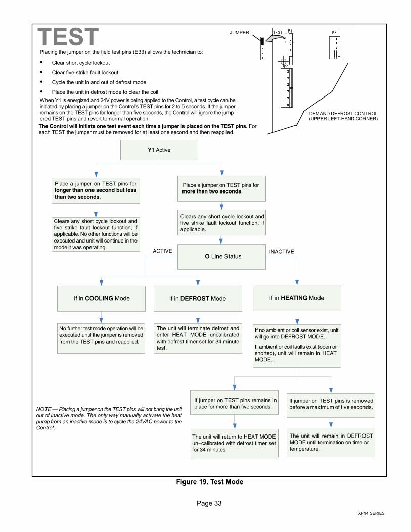
TESTPlacing the jumper on the field test pins (E33) allows the technician to:
� Clear short cycle lockout
� Clear five−strike fault lockout
� Cycle the unit in and out of defrost mode
� Place the unit in defrost mode to clear the coil
When Y1 is energized and 24V power is being applied to the Control, a test cycle can beinitiated by placing a jumper on the Control’s TEST pins for 2 to 5 seconds. If the jumperremains on the TEST pins for longer than five seconds, the Control will ignore the jump-ered TEST pins and revert to normal operation.
The Control will initiate one test event each time a jumper is placed on the TEST pins. Foreach TEST the jumper must be removed for at least one second and then reapplied.
NOTE � Placing a jumper on the TEST pins will not bring the unitout of inactive mode. The only way manually activate the heatpump from an inactive mode is to cycle the 24VAC power to theControl.
Y1 Active
Place a jumper on TEST pins forlonger than one second but lessthan two seconds.
Clears any short cycle lockout andfive strike fault lockout function, ifapplicable. No other functions will beexecuted and unit will continue in themode it was operating.
Place a jumper on TEST pins formore than two seconds.
Clears any short cycle lockout andfive strike fault lockout function, ifapplicable.
If in HEATING ModeIf in DEFROST Mode
No further test mode operation will beexecuted until the jumper is removedfrom the TEST pins and reapplied.
If no ambient or coil sensor exist, unitwill go into DEFROST MODE.
If ambient or coil faults exist (open orshorted), unit will remain in HEATMODE.
The unit will terminate defrost andenter HEAT MODE uncalibratedwith defrost timer set for 34 minutetest.
If jumper on TEST pins remains inplace for more than five seconds.
The unit will return to HEAT MODEun−calibrated with defrost timer setfor 34 minutes.
If jumper on TEST pins is removedbefore a maximum of five seconds.
The unit will remain in DEFROSTMODE until termination on time ortemperature.
O Line StatusINACTIVEACTIVE
If in COOLING Mode
DEMAND DEFROST CONTROL(UPPER LEFT−HAND CORNER)
JUMPER
Figure 19. Test Mode
Page 34
DEFROST BOARD DIAGNOSTICS
See table 9 to determine defrost board operational conditions and to diagnose cause and solution to problems.
Table 9. Defrost Control Board Diagnostic LEDs
DS2Green
DS1Red
Condition/Code Possible Cause(s) Solution
OFF OFF Power problemNo power (24V) to board terminals Rand C or board failure.
1 Check control transformer power (24V).2 If power is available to board and LED(s) do not
light, replace board.
SimultaneousSLOW Flash
Normal operationUnit operating normally or in standbymode.
None required.
Alternating SLOWFlash
5−minute anti−short cycledelay
Initial power up, safety trip, end ofroom thermostat demand.
None required (Jumper TEST pins to override)
SimultaneousFAST Flash
Ambient Sensor ProblemSensor being detected open or shorted or out of temperature range. Board will revert to time/temperature defrost operation. (System will still heat or cool).
Alternating FAST Flash
Coil Sensor ProblemSensor being detected open or shorted or out of temperature range. Board will not performdemand or time/temperature defrost operation. (System will still heat or cool).
ON ON Circuit Board FailureIndicates that board has internal component failure. Cycle 24 volt power to board. If code doesnot clear, replace board.
FAULT and LOCKOUT CODES (Each fault adds 1 strike to that code’s counter; 5 strikes per code = LOCKOUT)
OFFSLOWFlash
Low Pressure Fault 1 Restricted air flow over indoor oroutdoor coil.
2 Improper refrigerant charge insystem.
3 Improper metering device installed orincorrect operation of meteringdevice.
4 Incorrect or improper sensor locationor connection to system.
1 Remove any blockages or restrictions from coilsand/or fans. Check indoor and outdoor fan motor forproper current draws.
2 Check system charge using approach and subcool-ing temperatures.
3 Check system operating pressures and compare tounit charging charts.
4 Make sure all pressure switches and sensors havesecure connections to system to prevent refrigerantleaks or errors in pressure and temperature mea-surements.
OFF ON Low Pressure LOCKOUT
SLOWFlash
OFF High Pressure Fault
ON OFF High Pressure LOCKOUT
SLOWFlash
ONDischarge Line TemperatureFault
This model does not have a defrost line sensor, therefore this code is not applicable.FASTFlash
ONDischarge Line Temperature
LOCKOUT
OFFFastFlash
Discharge Sensor FaultThe XP14 series units does not use a defrost line sensor. However, a resistor is installedacross pins P4−1 and P4−2. If the resistor is missing or damage then this fault code will bedisplayed.
FastFlash
OFFDischarge Sensor
LOCKOUTThis model does not have a defrost line sensor, therefore this code is not applicable.
Maintenance
Maintenance and service must be performed by a qualifiedinstaller or service agency. At the beginning of eachcooling season, the system should be checked as follows:
Outdoor Unit
1. Clean and inspect the outdoor coil. The coil may beflushed with a water hose. Ensure the power is turnedoff before you clean the coil.
2. Outdoor fan motor is prelubricated and sealed. Nofurther lubrication is needed.
3. Visually inspect connecting lines and coils forevidence of oil leaks.
4. Check wiring for loose connections.
5. Check for correct voltage at the unit (with the unitoperating).
6. Check amp−draw outdoor fan motor.
UNIT NAMEPLATE: _________ ACTUAL: __________
NOTE − If owner reports insufficient cooling, the unit should
be gauged and refrigerant charge checked.
Outdoor Coil
It may be necessary to flush the outdoor coil morefrequently if it is exposed to substances which arecorrosive or which block airflow across the coil (e.g., peturine, cottonwood seeds, fertilizers, fluids that may containhigh levels of corrosive chemicals such as salts)
� Outdoor Coil � The outdoor coil may be flushed with
a water hose.
� Outdoor Coil (Sea Coast) � Moist air in ocean
locations can carry salt, which is corrosive to most
metal. Units that are located near the ocean requirefrequent inspections and maintenance. These
inspections will determine the necessary need to washthe unit including the outdoor coil. Consult your
installing contractor for proper intervals/proceduresfor your geographic area or service contract.
Page 35
XP14 SERIES
INDOOR UNIT
1. Clean or change filters.
2. Adjust blower speed for cooling. Measure the pressuredrop over the coil to determine the correct blower CFM.Refer to the unit information service manual for pressuredrop tables and procedure.
3. Check blower drive belt for wear and proper tension.
4. Check all wiring for loose connections
5. Check for correct voltage at unit (blower operating).
6. Check amp−draw on blower motor.
UNIT NAMEPLATE: _________ ACTUAL: __________
INDOOR COIL
1. Clean coil, if necessary.
2. Check connecting lines and coils for signs of oil leaks.
3. Check condensate line and clean, if necessary.
NOTE � The filter and all access panels must be in placeany time the unit is in operation.
Unit Wiring Diagram and Sequence of Operations
Figure 20. XP14 Unit Wiring Diagram (All Builds)
Page 36
SEQUENCE OF OPERATIONS
This is the sequence of operation for XP14 series units.The sequence is outlined by numbered steps whichcorrespond to circled numbers on the adjacent diagram.The steps are identical for both cooling and first stageheating demand with the exception reversing valve L1 isenergized during cooling demand and de−energized duringheating demand.
NOTE− Transformer in indoor unit supplies power (24 VAC)
to the thermostat and outdoor unit controls.
COOLING:
Internal thermostat wiring energizes terminal O by coolingmode selection, energizing the reversing valve L1.
1. Demand initiates at Y1 in the thermostat.
2. 24VAC energizes compressor contactor K1.
3. K1-1 N.O. closes, energizing compressor (B1) andoutdoor fan motor (B4).
END OF COOLING DEMAND:
1. Demand is satisfied. Terminal Y1 is de-energized.
2. Compressor contactor K1 is de-energized.
3. K1-1 opens and compressor (B1) and outdoor fanmotor (B4) are de-energized and stop immediately.
FIRST STAGE HEAT:
Internal thermostat wiring de−energizes terminal O byheating mode selection, de−energizing the reversing valveL1.
See steps 1, 2 and 3.
END OF FIRST STAGE HEAT:
See steps 4, 5 and 6.
DEFROST MODE:
When a defrost cycle is initiated, the control energizes thereversing valve solenoid and turns off the condenser fan.The control will also put 24VAC on the �W1" (auxiliary heat)line. The unit will stay in this mode until either the coilsensor temperature is above the selected terminationtemperature, the defrost time of 14 minutes has beencompleted, or the room thermostat demand cycle hasbeen satisfied. (If the temperature select shunt is notinstalled, the default termination temperature will be 90°F.)If the room thermostat demand cycle terminates the cycle,the defrost cycle will be held until the next room thermostatdemand cycle. If the coil sensor temperature is still belowthe selected termination temperature, the control willcontinue the defrost cycle until the cycle is terminated inone of the methods mentioned above. If a defrost isterminated by time and the coil temperature did not remainabove 35°F (2°C) for 4 minutes the control will go to the30−minute Time/Temperature mode.