49
2014

2014

NHP MODseries

MCCB Features & Benefits
Customer fit accessories. Saves time.
Easy to use accessories available for a wide range of applications
Flexible electronic or thermal magnetic OCR.
Ics rating is same as Icu rating. Easy application & selection of Ics
Quality product at an economical price. MODbreak is simply good value
Guaranteed and supported by NHP.
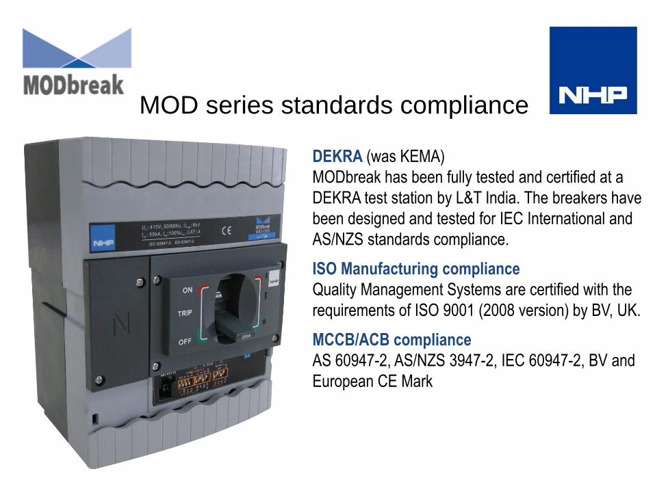
MOD series standards compliance
DEKRA (was KEMA)
MODbreak has been fully tested and certified at a
DEKRA test station by L&T India. The breakers have
been designed and tested for IEC International and
AS/NZS standards compliance.
ISO Manufacturing compliance
Quality Management Systems are certified with the
requirements of ISO 9001 (2008 version) by BV, UK.
MCCB/ACB compliance
AS 60947-2, AS/NZS 3947-2, IEC 60947-2, BV and
European CE Mark

MODbreak Isolation Insulation
Positive Isolation
The MCCB toggle indicates the true position of the main switching contacts
Touch proof insulation
• Internal accessories are housed in insulated casings to ensure IP20 protection.
• When the front cover is opened for the fixing of internal accessories, the MCCB is totally
insulated ensuring double insulation.

MODbreak Tripping & Anti Reclosing
Faster tripping The unique speed contact system accelerates
the opening of contacts during short circuit. This ensures faster
tripping an ultimate current limiting feature. The result-very low
let-through, cut-off current and fault clearing time
Mechanical Anti-reclosing
This unique feature ensures that under short circuit conditions,
the contacts open and latch even before the release gives a trip
command to the mechanism. This avoids contact re-closing and
bounce
Low Watts loss
The entire current carrying path is optimally designed to achieve
a low watts loss

MCCB’s
MB2 MB3 MB4

MODbreak Product Overview
Trip unit 415V kA MCCB type Current Catalogue
Frame Rating (A) ICU ICS Adjustment Number
250AF 63 – 250 36 36 Thermal Magnetic 80-100% MB2 - _ _ _ D3TM
250AF 63 – 250 50 50 Thermal Magnetic 80-100% MB2 - _ _ _ N3TM
250AF 40 – 250 36 36 Electronic 40-100% MB2 - _ _ _ D3SE
250AF 40 – 250 50 50 Electronic 40-100% MB2 - _ _ _ N3SE
630 AF 320- 630 36 36 Thermal Magnetic 80-100% MB3 - _ _ _ D3TM
630 AF 320 – 630 50 50 Thermal Magnetic 80-100% MB3 - _ _ _ N3TM
630AF 400 – 630 36 36 Electronic 40-100% MB3 - _ _ _ D3SE
630AF 400 – 630 50 50 Electronic 40-100% MB3 - _ _ _ N3SE
800 / 1250AF 800 - 1250 50 50 Electronic 40-100% MB4 - _ _ _ N3SE
Consists of:
• 3 or 4 pole MCCBs 14A to 1250A
• 36kA and 50kA types
• Thermal Magnetic and Electronic

MODbreak Frame Sizes / Amp Ratings
MCCB range overview
MB2
Rated current 63 (50A to 63A), 80, 100, 125, 160, 200, 250 A 40 (16A to 40A), 63, 100, 160, 250 A
Over Current Relay Thermal magnetic Electronic
MB3
Rated current 320, 400, 500, 630 A 400, 630 A
Over Current Relay Thermal magnetic Electronic
MB4
Rated current 800, 1000, 1250 A
Over Current Relay Electronic

MCCB Catalogue Numbers
MODbreak Catalogue Number System
MB 2 63 D 3 TM = which is an MB2 MCCB 63A 36KA 3P TM
MODbreak
Frame
2
3
4
kA rating
D=36
N=50
Amp rating
63
100
125
160
250
Poles
3
4
Protection
TM Thermal Magnetic
E Electronic
MTX1.0

MCCB’s OCRs
2 types of Trip Units (OCR)
Electronic
Thermal Magnetic

Thermal Magnetic MODbreak
• Adjustable overload setting 80% to 100% of ln
• Adjustable magnetic short circuit setting 6 – 10 ln
• Push to trip button
• True RMS sensing
• Infinite adjustment thermal and magnetic dials

Thermal Magnetic MODbreak
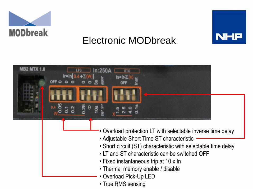
Electronic MODbreak
• Overload protection LT with selectable inverse time delay
• Adjustable Short Time ST characteristic
• Short circuit (ST) characteristic with selectable time delay
• LT and ST characteristic can be switched OFF
• Fixed instantaneous trip at 10 x In
• Thermal memory enable / disable
• Overload Pick-Up LED
• True RMS sensing

Dip Switches Examples of Settings (for each trip unit) 0.4 0.05 0.1 0.2 0.25 In 40A 100A 250A 400A 630A 800A 1000A 1250A
I I I I I 1.00 x In 40 100 250 400A 630 800 1000 1250 I O I I I 0.95 x In 38 95 238 380 599 760 950 1187 I I O I I 0.90 x In 36 90 225 360 567 720 900 1125 I O O I I 0.85 x In 34 85 213 340 536 680 850 1062 I I I O I 0.80 x In 32 80 200 320 504 640 800 1000 I I I I O 0.75 x In 30 75 188 300 473 600 750 937 I O I I O 0.70 x In 28 70 175 280 441 560 700 875 I I O I O 0.65 x In 26 65 163 260 410 520 650 812 I O O I O 0.60 x In 24 60 150 240 378 480 600 750 I I I O O 0.55 x In 22 55 138 220 347 440 550 687 I O I O O 0.50 x In 20 50 125 200 315 400 500 675 I I O O O 0.45 x In 18 45 113 180 284 360 450 562 I O O O O 0.40 x In 16 40 100 160 252 320 400 500
Electronic MODbreak Long Time (LT) Setting
EXAMPLE 250A Trip Unit
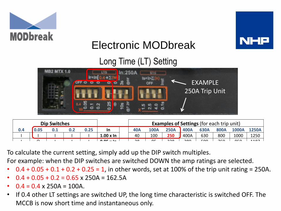
Dip Switches Examples of Settings (for each trip unit) 0.4 0.05 0.1 0.2 0.25 In 40A 100A 250A 400A 630A 800A 1000A 1250A
I I I I I 1.00 x In 40 100 250 400A 630 800 1000 1250 I O I I I 0.95 x In 38 95 238 380 599 760 950 1187 I I O I I 0.90 x In 36 90 225 360 567 720 900 1125 I O O I I 0.85 x In 34 85 213 340 536 680 850 1062 I I I O I 0.80 x In 32 80 200 320 504 640 800 1000 I I I I O 0.75 x In 30 75 188 300 473 600 750 937 I O I I O 0.70 x In 28 70 175 280 441 560 700 875 I I O I O 0.65 x In 26 65 163 260 410 520 650 812 I O O I O 0.60 x In 24 60 150 240 378 480 600 750 I I I O O 0.55 x In 22 55 138 220 347 440 550 687 I O I O O 0.50 x In 20 50 125 200 315 400 500 675 I I O O O 0.45 x In 18 45 113 180 284 360 450 562 I O O O O 0.40 x In 16 40 100 160 252 320 400 500
Long Time (LT) Setting
Electronic MODbreak
To calculate the current setting, simply add up the DIP switch multiples. For example: when the DIP switches are switched DOWN the amp ratings are selected. • 0.4 + 0.05 + 0.1 + 0.2 + 0.25 = 1, in other words, set at 100% of the trip unit rating = 250A. • 0.4 + 0.05 + 0.2 = 0.65 x 250A = 162.5A • 0.4 = 0.4 x 250A = 100A. • If 0.4 other LT settings are switched UP, the long time characteristic is switched OFF. The
MCCB is now short time and instantaneous only.
EXAMPLE 250A Trip Unit
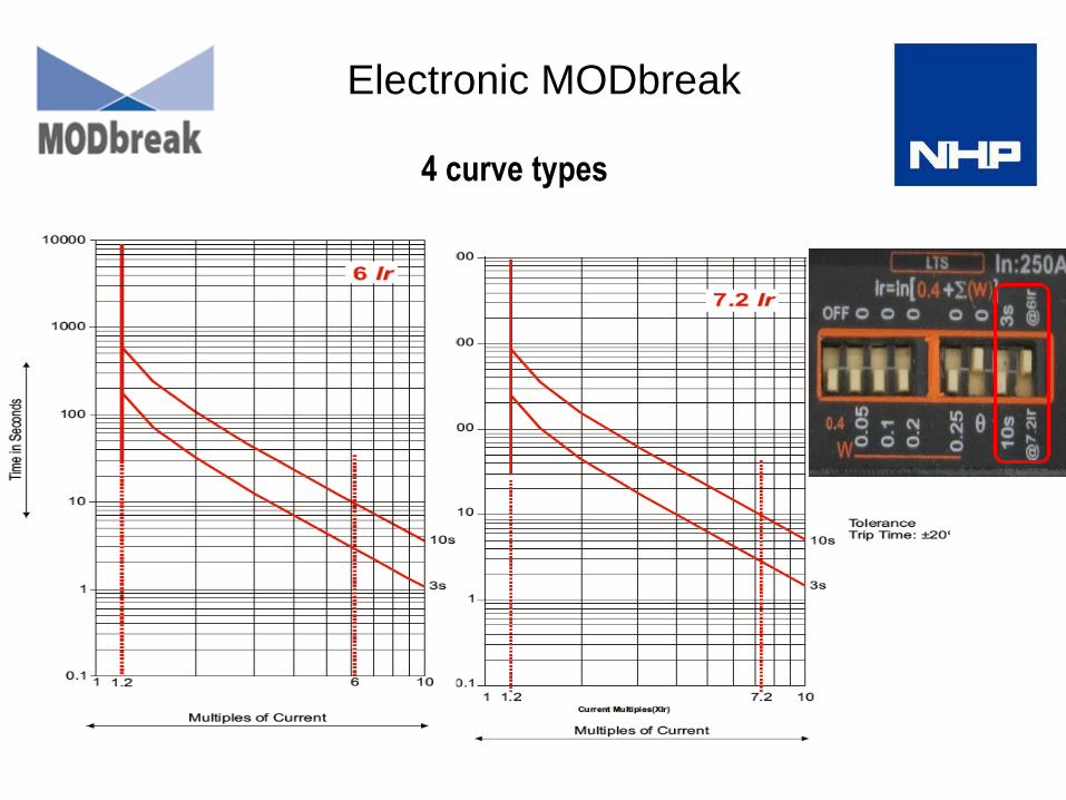
4 curve types
Electronic MODbreak

6 x Short Time Adjustments
Dip Switches
1.5 2.5 4 STS Setting
I O O 1.50 x Ir
O I O 2.50 x Ir O O I 4.00 x Ir
I O I 5.50 x Ir
O I I 6.50 x Ir
I I I 8.00 x Ir
O O O STS Off (10 x In)
Electronic MODbreak

OCR – Short Time Adjustment
1.5 2.5 4.0 5.5 6.5 8.0
Time
Current
Electronic MODbreak
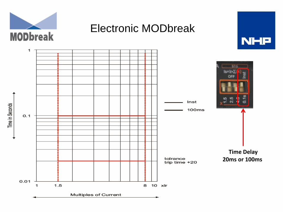
Electronic MODbreak
Time Delay 20ms or 100ms

OCR – Thermal Memory
Electronic MODbreak
Thermal Memory available on the MTX 1.0 Electronic trip unit.
The thermal memory feature is enabled or disabled by switching the DIP switch above the
symbol θ on the OCR facia: Up = OFF / Down = ON.
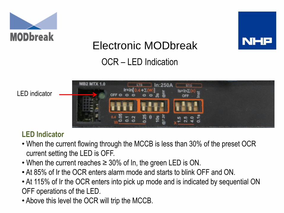
OCR – LED Indication
LED indicator
LED Indicator
• When the current flowing through the MCCB is less than 30% of the preset OCR
• current setting the LED is OFF.
• When the current reaches ≥ 30% of In, the green LED is ON.
• At 85% of Ir the OCR enters alarm mode and starts to blink OFF and ON.
• At 115% of Ir the OCR enters into pick up mode and is indicated by sequential ON
OFF operations of the LED.
• Above this level the OCR will trip the MCCB.
Electronic MODbreak
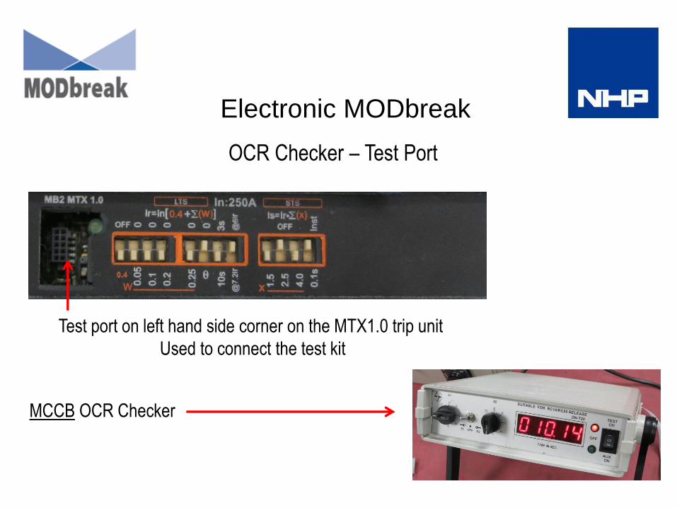
Test port on left hand side corner on the MTX1.0 trip unit
Used to connect the test kit
MCCB OCR Checker
Electronic MODbreak
OCR Checker – Test Port

Selectivity MCCB to MCCB
Upstream MB3 MCCB Electronic
50kA
MB4 MCCB Electronic
50kA
Downstream Current
Rating 400A 630A 800A 1000A 1250A
MB2 - TM
MB2 - E
36kA
or
50kA
63 20 / 50 20 / 50 36 / 50 36 / 50 36 / 50
80 20 / 50 20 / 50 36 / 50 36 / 50 36 / 50
100 20 / 50 20 / 50 36 / 50 36 / 50 36 / 50
125 20 / 50 20 / 50 36 / 50 36 / 50 36 / 50
160 20 / 50 20 / 50 36 / 50 36 / 50 36 / 50
200 20 / 50 20 / 50 36 / 50 36 / 50 36 / 50
250 20 / 50 20 / 50 36 / 50 36 / 50 36 / 50
MB3 TM or E
36kA or 50kA
400 - - 36 / 50 36 / 50 36 / 50
630 - - 36 / 50 36 / 50 36 / 50
• The upstream MCCB is an electronic type with an MTX1 trip unit.
• The downstream MCCB can be electronic or thermal magnetic types, rated 36kA or 50kA.
• For an upstream table with 36kA electronic MCCBs refer MODbreak Technical Catalogue.

Selectivity & Cascading MCB to MCCB thermal magnetic
Refer MODbreak Technical Catalogue for 36kA table

Selectivity & Cascading MCB to MCCB Electronic
Refer MODbreak Technical Catalogue for 36kA table

MODbreak accessory products
• Auxiliaries
• Alarms
• Shunts Trips
• Under Voltage Trips
• Extension handles
• Extension handle mechanism locks
• Direct mount handles
• Captive toggle locks
• Motor operators
• Interlocks
• Terminal covers
• Busbar extensions
• OCR checker
• Chassis
• Transfer switches
• Transfer switch controller
• MODcurve Selectivity software
• CAD blocks & 3D drawings
INTERNAL ACCESSORRIES
EXTERNAL ACCESSORRIES
OTHER ACCESSORRIES

Accessory fitting
• Accessories are customer fit.
• The only exceptions are motor operators which need
to be fitted in NHP manufacturing or branch workshops
so as to enable correct fitting and testing.
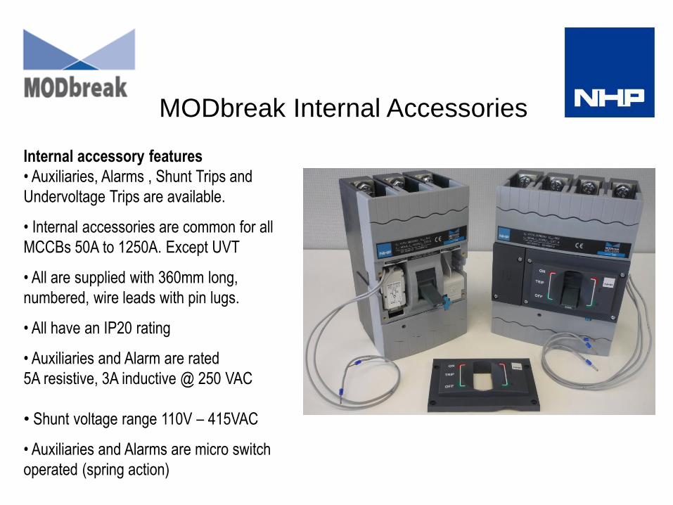
MODbreak Internal Accessories
Internal accessory features
• Auxiliaries, Alarms , Shunt Trips and
Undervoltage Trips are available.
• Internal accessories are common for all
MCCBs 50A to 1250A. Except UVT
• All are supplied with 360mm long,
numbered, wire leads with pin lugs.
• All have an IP20 rating
• Auxiliaries and Alarm are rated
5A resistive, 3A inductive @ 250 VAC
• Shunt voltage range 110V – 415VAC
• Auxiliaries and Alarms are micro switch
operated (spring action)

MODbreak Internal Accessories
Internal accessory installation
• Auxiliaries, Alarms, and shunts fit on either side of the MCCB
• UVTs fit on the left side of the MCCB only
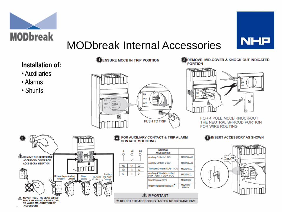
MODbreak Internal Accessories
Installation of:
• Auxiliaries
• Alarms
• Shunts
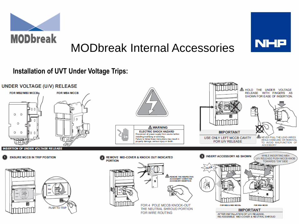
MODbreak Internal Accessories
Installation of UVT Under Voltage Trips:
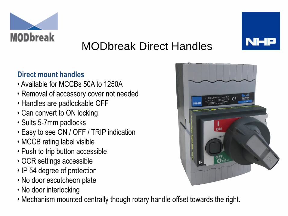
MODbreak Direct Handles
Direct mount handles
• Available for MCCBs 50A to 1250A
• Removal of accessory cover not needed
• Handles are padlockable OFF
• Can convert to ON locking
• Suits 5-7mm padlocks
• Easy to see ON / OFF / TRIP indication
• MCCB rating label visible
• Push to trip button accessible
• OCR settings accessible
• IP 54 degree of protection
• No door escutcheon plate
• No door interlocking
• Mechanism mounted centrally though rotary handle offset towards the right.
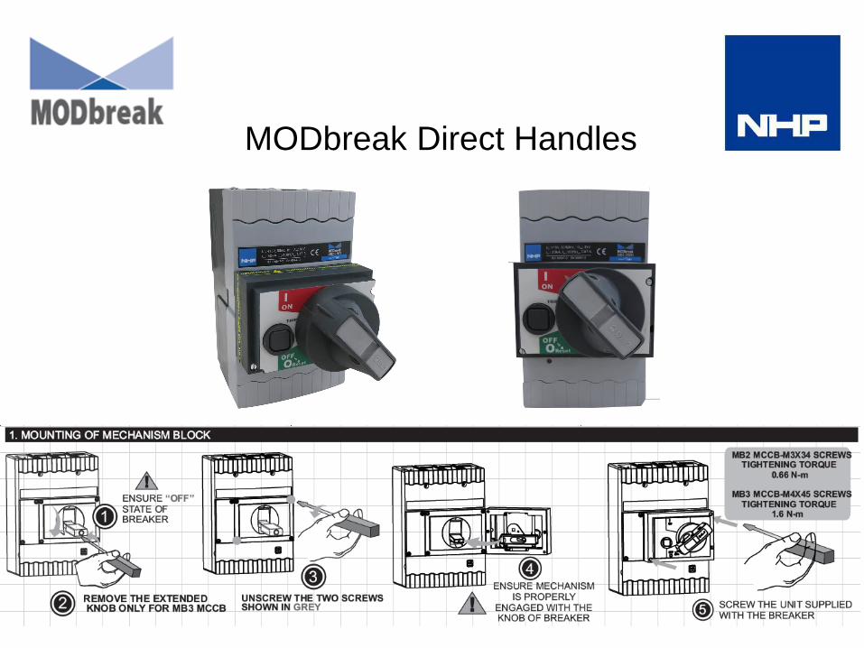
MODbreak Direct Handles
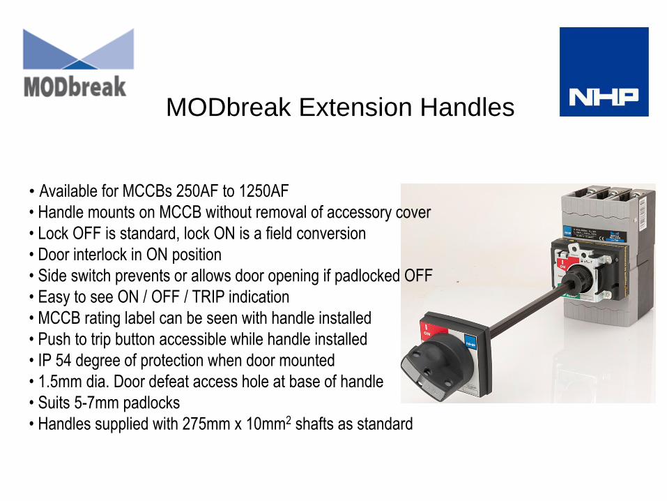
MODbreak Extension Handles
• Available for MCCBs 250AF to 1250AF
• Handle mounts on MCCB without removal of accessory cover
• Lock OFF is standard, lock ON is a field conversion
• Door interlock in ON position
• Side switch prevents or allows door opening if padlocked OFF
• Easy to see ON / OFF / TRIP indication
• MCCB rating label can be seen with handle installed
• Push to trip button accessible while handle installed
• IP 54 degree of protection when door mounted
• 1.5mm dia. Door defeat access hole at base of handle
• Suits 5-7mm padlocks
• Handles supplied with 275mm x 10mm2 shafts as standard

MODbreak Extension Handles
Unique variable depth handle locking features
• Padlock OFF without door interlock – door can be opened
• Padlock OFF with door interlock - door cannot be opened
• Padlock ON with door interlock – door cannot be opened
unless side door defeat slide switch is used, refer below.
• For padlock ON, field convert padlock OFF handles.
Door interlock padlocking
selection lever
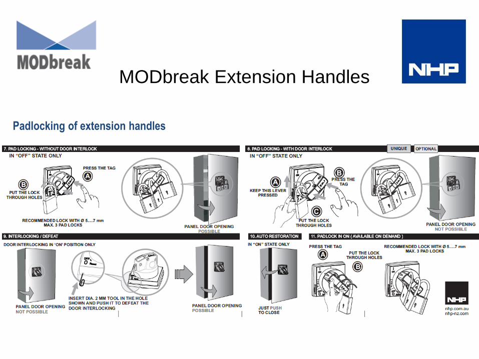
MODbreak Extension Handles
Padlocking of extension handles

MODbreak Extension Handles
Installation of extension handles

Locking MODbreak MCCBs
Handles
• Handles can be padlocked OFF as standard
• On padlocking handles are also available.
Motor operator for MCCBs
• Motors can be padlocked while the MCCB is OFF
MCCB toggles
• A screw on direct mount padlock mechanism is
available for all sizes to padlock MCCBs OFF or ON
Trapped key interlocking
• Prosafe and other types of trapped key locks can be
used with extension shaft handles.

Locking MODbreak MCCBs
Captive padlock mechanism
A Stainless Steel lock attachment can be customer fitted via 4 mounting screws
Captive lock attachment fitted Lock OFF Lock ON

MODbreak Terminal Covers
Terminal cover options
• Available for MCCBs 250AF to 1250A
• Wide and narrow terminal covers on MB2 / MB3
• Narrow cover only for MB4
• Wide covers physically longer for larger cables or busbars
• Flush terminal covers for MB2 / MB3
• 3 and 4 pole covers
• Covers come complete with IP20 end cover knock outs
• Increases IP Form for switchboard construction
• Rigid rubber interpole barriers standard supply with MCCBs
• Covers designed for chassis mounted MCCBs
• Electrical probe test access holes
• Screwdriver access points for easy cover removal

MODbreak Motor Operators
Motor operators
• For 250AF and 630AF MCCBs
• ON / OFF & Charged/Discharged indication
• Spring charge mechanism
• Selector switch for Auto/Manual operation and padlocking
• Padlock facility for locking in OFF position (up to 3 padlocks)
• High mechanical & electrical endurance
• Accessible internal 1.6A fuse for extended motor life
• Access to the MCCB OCR when motor fitted
• MCCB right side internal accessory pocket occupied when motor fitted
• The motor consists of 1 x motor and 1 x special signaling auxiliary that mounts in the MCCB. The
internal signaling auxiliary activates the ON TRIP CHARGED and DISCHARGED indication on the motor.
• For this reason at this time, motors will be a factory or branch fit only in order to enable NHP testing.
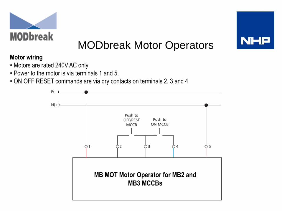
MB MOT Motor Operator for MB2 and
MB3 MCCBs
MODbreak Motor Operators Motor wiring
• Motors are rated 240V AC only
• Power to the motor is via terminals 1 and 5.
• ON OFF RESET commands are via dry contacts on terminals 2, 3 and 4

MODbreak Transfer Switches
Basic Transfer Switches
MODbreak transfer switches are available from 20A to 630A, and consist
of mechanically and electrically interlocked MCCBs, with motors fitted.
The transfer switches come pre-wired on metal panels, with 240V motors
Automatic Transfer Switches
Basic Transfer Switches can be coupled with TemLogic TL101CIP
electronic changeover controllers to enable Automatic Transfer.
Manual Transfer Switches
Manual transfer switches are assembled by the user, using interlock kits
and MCCBs that are ordered from the MCCB and accessories pages in
this catalogue. MTS can be operated either directly by the MCCB toggles
or by handle operators.
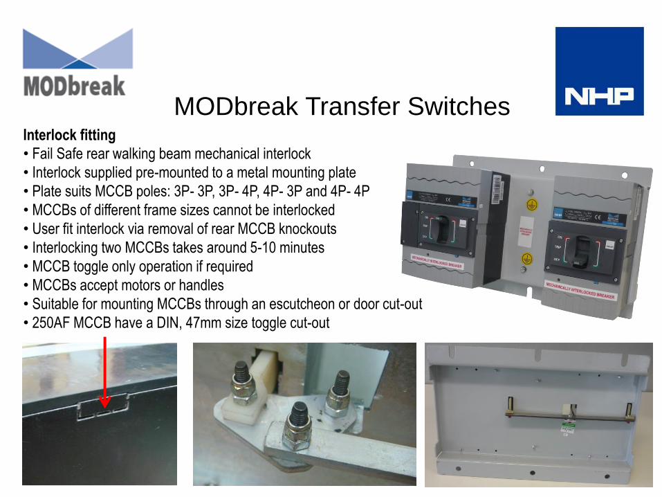
MODbreak Transfer Switches Interlock fitting
• Fail Safe rear walking beam mechanical interlock
• Interlock supplied pre-mounted to a metal mounting plate
• Plate suits MCCB poles: 3P- 3P, 3P- 4P, 4P- 3P and 4P- 4P
• MCCBs of different frame sizes cannot be interlocked
• User fit interlock via removal of rear MCCB knockouts
• Interlocking two MCCBs takes around 5-10 minutes
• MCCB toggle only operation if required
• MCCBs accept motors or handles
• Suitable for mounting MCCBs through an escutcheon or door cut-out
• 250AF MCCB have a DIN, 47mm size toggle cut-out

MODbreak MB 250A chassis
• MB Chassis
• Suits MODbreak 250 Amp Frame thermal magnetic or electronic MCCBs.
• Double sided
• Chassis rated with an Icw of 36 kA for 1 second, 40 kA for 0.5 seconds.
• Form 2 separation
• No specials

MODbreak MBC chassis
Features:
• Suits 250AF and 630AF MODbreak MCCBs 50A to 630A.
• MBC chassis suits MODbreak only (different tee offs and brackets)
• Double sided chassis types for 3 pole MCCBs
• 1250 A, 1600 A or 2200 A rated main bars.
• 11 enclosure sizes to suit application height space.
• Front connect tags supplied as standard.
• Complies with AS/NZS 3439, AS/NZS 3000 – 2007.
• Form of separation, up to 4bih. AS/NZS 3439.1: 2000 (Annex ZF).
• MCCBs reverse connected as standard.
• MCCBs front connected, not rear connected as is TemBreak 2
• Assembled to order from stocked parts by NHP

MODbreak Connection & Orientation
Forward or Reverse connection
MODbreak MCCBs can be forward or reverse connected to
allow reversal of line and load connections. This is especially
important for MB and MBH chassis where MODbreak MCCBs
are reverse connected on chassis as standard.
Mounting angle
The MODbreak mounting angle does not affect performance

Information
ACB’s
A4 selection and price catalogue
ACB manual
ACB OCR quick set up guide
Rating chart
Cad Blocks
Wiring diagram
Individual instructions of part fitting
• Shunt Coil
• Under voltage coil
• Closing coil
• Motor Operator
• Mechanical Interlock
• Prosafe key interlock
MCCB’s
A4 selection and price catalogue
MODcurve grading software
Rating Chart
Cad Blocks
Cascade/Selectivity table
Electronic OCR setting guide
Individual instructions of MCCB’s, accessory fitting
MB 800 amp chassis drawings
MBC High current chassis drawing
MBC chassis order form
BTS drawings and logic control
INTERNET Accessed Product Information


