The PDF of the article you requested follows this cover page. This is an enhanced PDF from The Journal of Bone and Joint Surgery 88:156-174, 2006. doi:10.2106/JBJS.F.00745 J. Bone Joint Surg. Am. S. Robert Rozbruch, Austin T. Fragomen and Svetlana Ilizarov Frame Correction of Tibial Deformity with Use of the Ilizarov-Taylor Spatial This information is current as of December 15, 2006 Reprints and Permissions Permissions] link. and click on the [Reprints and jbjs.org article, or locate the article citation on to use material from this order reprints or request permission Click here to Publisher Information www.jbjs.org 20 Pickering Street, Needham, MA 02492-3157 The Journal of Bone and Joint Surgery on December 15, 2006 www.ejbjs.org Downloaded from
Transcript
The PDF of the article you requested follows this cover page.
This is an enhanced PDF from The Journal of Bone and Joint Surgery
88:156-174, 2006. doi:10.2106/JBJS.F.00745 J. Bone Joint Surg. Am.S. Robert Rozbruch, Austin T. Fragomen and Svetlana Ilizarov
FrameCorrection of Tibial Deformity with Use of the Ilizarov-Taylor Spatial
This information is current as of December 15, 2006
Reprints and Permissions
Permissions] link. and click on the [Reprints andjbjs.orgarticle, or locate the article citation on
to use material from thisorder reprints or request permissionClick here to
Publisher Information
www.jbjs.org20 Pickering Street, Needham, MA 02492-3157The Journal of Bone and Joint Surgery
Ilizarov-Taylor Spatial FrameBY S. ROBERT ROZBRUCH, MD, AUSTIN T. FRAGOMEN, MD, AND SVETLANA ILIZAROV, MD
Introductionhe Ilizarov-Taylor Spatial Frame (TSF; Smith and Nephew,Memphis, Tennessee) is a powerful tool for correctingtibial deformity1-6. A specialized feature of the TSF is its
virtual hinge, which allows for the simultaneous gradual correc-tion of multiplanar deformities and limb-lengthening throughone osteotomy site. The power of the spatial frame lies in itsprecise control over the final limb length and alignment and inits ability to correct a residual deformity. The stability of thismultiplanar circular fixator permits early weight-bearing andprovides an ideal environment for both new-bone formationand soft-tissue healing. The classic principles of the Ilizarovmethod are followed to ensure proper frame application. TheTSF web-based software is user-friendly and has greatly sim-plified the planning of the correction of an oblique plane de-formity by utilizing standard anterior-posterior and lateralradiographic measurements. Computer-generated schedulesand easy-to-read struts have greatly simplified patient involve-ment, which is crucial to the success of this technique.
Surgical TechniquePreoperative Planning
atients are evaluated clinically by a history and physical ex-amination including observation of gait. Special attention is
directed toward the assessment of leg length, mechanical axisdeviation, and rotational alignment (Fig. 1). An erect bipedal51-in (130-cm) radiograph in the frontal plane is made. If thereis a leg-length discrepancy, then blocks are placed under the af-fected foot to level the pelvis, and the block height is recorded.Accurate limb lengths are measured in this way. Sagittal defor-mity about the knee is evaluated with a 36-in (91-cm) lateralradiograph made with the knee in full extension. Routine an-teroposterior and lateral radiographs of the tibia are made aswell. Ankle deformity should be evaluated with the x-ray beamcentered on the ankle. Mechanical axis deviation is determinedwith use of the malalignment test7,8 (Fig. 2). The lateral distalfemoral angle, medial proximal tibial angle, and posterior prox-imal tibial angle are measured to analyze deformities of theproximal part of the tibia. The lateral distal tibial angle and an-terior distal tibial angle are measured for distal tibial deformi-ties. The center of rotation of angulation7,8 is identified bylocating the intersection of the proximal and distal tibial me-chanical axes (Fig. 3). Often this point is chosen to be the origin
as well. (In TSF terminology, the origin, in many ways, marksthe location of the virtual hinge.) Proper placement of thathinge greatly affects the correction.
An osteotomy site is selected, typically at the apex ofthe deformity. If the bone is very sclerotic at the apex, thenan adjacent alternative site is used to maximize bone-healingpotential. When making an osteotomy at a site other thanthe center of rotation of angulation, one must translate thebone to reestablish alignment. The amount of osseous trans-
T
P
Fig. 1
This varus deformity is associated with tibial
shortening.
Rozbruch.fm Page 156 Monday, October 30, 2006 2:59 PM
THE JOU R N A L OF BO N E & JO I N T SU RG ER Y · JB JS .ORG
VO LUM E 88-A · SU P P L E M E N T 4 · 2006COR RE CT ION OF TIBIA L DEFOR M IT Y W IT H US E OF TH E IL I ZA ROV-TAY LOR SPA T I A L FR A M E
lation in the anterior-posterior and medial-lateral planes ismeasured at the proposed osteotomy site. These values areentered into the computer as deformity parameters to ensurethat the distal fragment will be well aligned at the comple-tion of the adjustment period (Figs. 4-A through 4-F, 5-A,5-B, and 6).
When a stiff tibial nonunion with a deformity is cor-rected, often no tibial osteotomy is needed1,2,5. Osteotomy ofthe fibula is required in most patients undergoing tibial os-teotomy as correction of most tibial deformities relies on amobile fibula. For patients with an infected tibial nonunion,
antibiotics are stopped two to six weeks before surgery to im-prove the accuracy of intraoperative cultures.
Fig. 2
This image shows the majority of a 51-in (130-cm) standing
bipedal radiograph of the patient in Figure 1. A 78-mm medial
mechanical axis deviation (MAD) is demonstrated.
Fig. 3
The mechanical axis of the femur is drawn (solid line), and the lateral
distal femoral angle is measured at 87°. Since this is a normal joint ori-
entation, the femoral mechanical axis is extended distally to become
the mechanical axis of the proximal part of the tibia. The mechanical
axis of the distal part of the tibia is extended proximally (dotted line)
until the two lines intersect. This point is the center of rotation of angu-
lation (yellow) of the deformity. There is a 30° varus deformity.
Rozbruch.fm Page 157 Monday, October 30, 2006 2:59 PM
THE JOU R N A L OF BO N E & JO I N T SU RG ER Y · JB JS .ORG
VO LUM E 88-A · SU P P L E M E N T 4 · 2006COR RE CT ION OF TIBIA L DEFOR M IT Y W IT H US E OF TH E IL I ZA ROV-TAY LOR SPA T I A L FR A M E
Operating-Room SetupThe patient is taken to the operating room and placed supineon a radiolucent operating table. Sheets are placed under theipsilateral hip to internally rotate the lower extremity until thepatella is pointing directly toward the ceiling (Fig. 7). Regionalepidural anesthesia is typically used to provide analgesia forthe surgery. Paralyzing medications are not used as they maymask early signs of nerve irritation from a glancing wire. Adose of prophylactic antibiotics with gram-positive coverage isadministered in the operating room prior to the skin incision.If infection is suspected, then the preoperative antibiotics arewithheld until five deep intraoperative cultures have been ob-tained. C-arm fluoroscopy is used throughout the procedureto ensure ideal positioning of the fixator and to allow for theimplementation of minimally invasive techniques. The c-armis positioned on the side of the contralateral leg.
Fibular OsteotomyA fibular osteotomy is carried out under tourniquet controland is performed at the level of the fibular deformity. In gen-eral, we try to avoid creating a fibular osteotomy at the samelevel as the tibial osteotomy for fear of compromising the localblood supply and bone-healing. A direct approach is made tothe fibula through the interval between the peroneal musclesand the soleus. Care is taken when performing the subperi-osteal dissection as the motor branch to the extensor hallucislongus lies close to the anteromedial border of the fibula. Thesoft tissue is protected with Hohmann retractors exposing thefibular diaphysis. If a lengthening is needed, then the fibula ispredrilled with an Ilizarov wire and the osteotomy is com-pleted with a narrow osteotome (Fig. 8). If an angular correc-tion with minimal lengthening is performed, then an obliquefibular osteotomy is made with an oscillating saw as this cutconfiguration allows the fibular bone ends to slide andshorten. At times, we resect a small section of the fibula if sub-stantial fibular shortening is anticipated or if early fibular con-solidation is anticipated. The fascia is left open, and the skin isclosed in layers. The tourniquet is then deflated for the re-mainder of the operation.
Proximal Ring ApplicationThe frame is then applied to the limb before creating the tibialosteotomy. The technique that we use to apply the TSF is the“rings first” method4. We favor this technique because it freesthe rings for ideal placement on the leg with regard to the softtissues. The tourniquet is not recommended for this portionof the surgery as it is thought that adequate blood flow isneeded to cool the wires and drills as they pass through thebone and soft tissues. A common location for the tibial osteot-omy used for deformity correction is in the proximal metaph-ysis just distal to the tibial tubercle. The following techniqueillustrates the method we use for proximal tibial osteotomy.The same principles for frame mounting and osteotomy canbe applied at any level of the tibia. With use of the fluoro-scopic anteroposterior projection, a smooth 1.8-mm Ilizarovwire is advanced across the proximal tibial metaphysis from
lateral to medial, perpendicular to the proximal tibial me-chanical axis. The wire should start 14 mm distal to the lateraltibial plateau in order to remain out of the joint capsule9. Oncethis wire has been placed, the proximal ring is centered on theleg and the wire is tensioned (Figs. 9 and 10). We prefer to usea 2/3 ring proximally to accommodate posterior leg swellingand allow knee flexion. The ring is held in a position orthogo-nal to the mechanical axis of the tibia in the sagittal plane (Fig.11). A second wire is placed through the fibular head, exitingthe anteromedial part of the tibia. The fibular wire is neededwhen planning a lengthening or a large rotational correction.When placing wires through the fibular head, great care is
Fig. 4-A
This image is a magnification of the image in Figure 3. The center
of rotation of angulation (yellow) is the same as the origin in this exam-
ple. The proximal bone fragment was selected as the reference
fragment. Therefore, the origin lies on the proximal (reference) mechan-
ical axis line. The frame hinges on the origin. In this example, the origin
is in the center of the deformity. A central hinge will create a neutral
wedge correction (an opening wedge correction in the concavity of the
curve and a closing wedge correction along the convexity of the curve).
Because no bone is being removed, one must prevent the bone on the
convexity from compressing, fracturing, or blocking the deformity cor-
rection. This is accomplished by lengthening the osteotomy. How much
lengthening is needed is calculated in the following figures with use of
the local analysis method. A line is drawn from the origin to the surface
of the tibial convex cortex, and its length (L) is recorded. That line rep-
resents the width of bone that would otherwise impinge.
Rozbruch.fm Page 158 Monday, October 30, 2006 2:59 PM
THE JOU R N A L OF BO N E & JO I N T SU RG ER Y · JB JS .ORG
VO LUM E 88-A · SU P P L E M E N T 4 · 2006COR RE CT ION OF TIBIA L DEFOR M IT Y W IT H US E OF TH E IL I ZA ROV-TAY LOR SPA T I A L FR A M E
The deformity parameters are entered into the computer, and anteroposterior, lateral, and axial stick images are generated. These images can be
compared with the radiographs to ensure that the correct information has been input.
taken to avoid damaging the common peroneal nerve (Fig.12). The wire is then advanced in a normal fashion, alwayswatching the foot for motion. Once the wire tip has crossedthrough the leg and has exited the skin, the drill is removedand the wire is tapped through the remainder of the way. Ahalf-pin is placed anterolateral at Gerdy’s tubercle in a pos-teromedial direction. An additional half-pin is placed froman anteromedial starting point and is inserted in a postero-lateral direction (Fig. 13). We advocate the use of hydroxy-apatite-coated half-pins for this procedure. These pins havebeen associated with a decreased rate of loosening and,subsequently, the perception of a lower rate of pin-siteinfection10.
Mounting ParametersOnce the proximal ring is secured, the mounting parametersare calculated. The mounting parameters are a set of measure-
ments that inform the computer of the location of the refer-ence ring with respect to the origin. Although any ring can beselected to be the reference ring, the ring closest to the osteot-omy site is typically selected to be the reference ring. For aproximal tibial osteotomy, the proximal ring is used as the ref-erence ring. The position of the center of the ring with respectto the origin in the coronal, sagittal, and axial planes is mea-sured in millimeters (Figs. 14-A through 14-G). These valuesare recorded for later use in the creation of a schedule for strutadjustments.
Distal Ring ApplicationAttention is then turned to the distal ring. Some thoughtshould be given to determining the optimal distance betweenthe rings. This will help to minimize the number of strutchanges, which are an inconvenience to the patient and thesurgeon. Typically, medium struts are used, and they are set in
Fig. 6
Rozbruch.fm Page 161 Tuesday, November 7, 2006 11:09 AM
THE JOU R N A L OF BO N E & JO I N T SU RG ER Y · JB JS .ORG
VO LUM E 88-A · SU P P L E M E N T 4 · 2006COR RE CT ION OF TIBIA L DEFOR M IT Y W IT H US E OF TH E IL I ZA ROV-TAY LOR SPA T I A L FR A M E
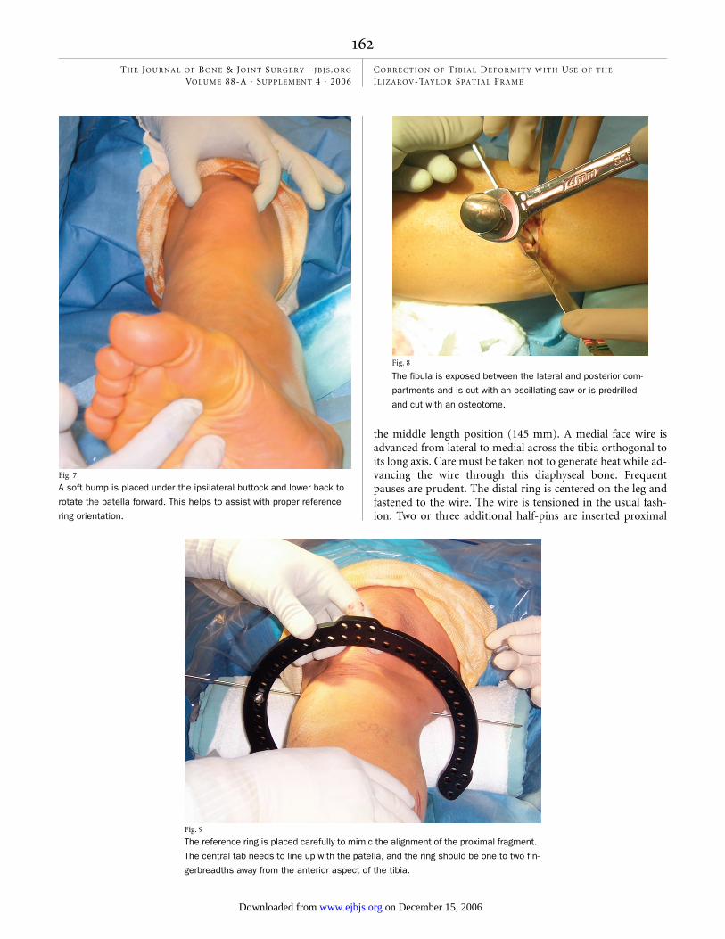
the middle length position (145 mm). A medial face wire isadvanced from lateral to medial across the tibia orthogonal toits long axis. Care must be taken not to generate heat while ad-vancing the wire through this diaphyseal bone. Frequentpauses are prudent. The distal ring is centered on the leg andfastened to the wire. The wire is tensioned in the usual fash-ion. Two or three additional half-pins are inserted proximal
Fig. 8
Fig. 7
A soft bump is placed under the ipsilateral buttock and lower back to
rotate the patella forward. This helps to assist with proper reference
ring orientation.
The fibula is exposed between the lateral and posterior com-
partments and is cut with an oscillating saw or is predrilled
and cut with an osteotome.
Fig. 9
The reference ring is placed carefully to mimic the alignment of the proximal fragment.
The central tab needs to line up with the patella, and the ring should be one to two fin-
gerbreadths away from the anterior aspect of the tibia.
Rozbruch.fm Page 162 Monday, October 30, 2006 2:59 PM
THE JOU R N A L OF BO N E & JO I N T SU RG ER Y · JB JS .ORG
VO LUM E 88-A · SU P P L E M E N T 4 · 2006COR RE CT ION OF TIBIA L DEFOR M IT Y W IT H US E OF TH E IL I ZA ROV-TAY LOR SPA T I A L FR A M E
and distal to the distal ring, preferably in different planes,yielding a total of three or four points of fixation distally. Al-ternatively, a ring block that consists of two rings and a total offour to five points of fixation can be used (Fig. 15).
The six struts are attached to the proximal ring andtightened. The struts are secured to the distal ring without in-troducing any tension or compression forces to the system.Free rotation of the struts should be possible as the shoulderbolts spin through the ring. The strut lengths are recorded(Fig. 16).
Foot Ring ApplicationAt times, the addition of a foot ring is required. The mostcommon indication to include a foot ring while correcting atibial deformity is to treat an equinus contracture of the anklejoint. Hinges placed along the oblique axis of the ankle allowfor constrained gradual restoration of a plantigrade foot whileprotecting the articular surface (Figs. 17-A through 17-D).The foot is also included in cases of very distal tibial osteoto-mies where adequate stability cannot be obtained with use ofthe distal tibial ring alone. The addition of a foot ring greatlyincreases the stability of the distal ring block. As healingprogresses, the foot ring is removed in the office to dynamizethe osteotomy. If an equinus deformity had occurred as theresult of a prior unrecognized anterior compartment syn-drome, then great caution must be exercised in placing wirefixation through an anterior compartment that contains ne-crotic muscle tissue as this can lead to severe infection. Theopen section of the foot ring is closed with a half-ring or aconnecting rod. The ring is then attached to the foot with twocrossing oblique calcaneal wires and one midfoot wire.
Fig. 10
The ring in this example was placed perpendicular to the
desired proximal tibial mechanical axis.
Fig. 11
The lateral radiograph confirms a desirable sagittal ring orientation.
Rozbruch.fm Page 163 Monday, October 30, 2006 2:59 PM
THE JOU R N A L OF BO N E & JO I N T SU RG ER Y · JB JS .ORG
VO LUM E 88-A · SU P P L E M E N T 4 · 2006COR RE CT ION OF TIBIA L DEFOR M IT Y W IT H US E OF TH E IL I ZA ROV-TAY LOR SPA T I A L FR A M E
Tibial OsteotomyTo carry out the tibial osteotomy, the struts are detachedfrom the proximal ring. The tibial osteotomy should be madedistal to the tibial tubercle to prevent involvement of the ex-tensor mechanism, but it should be proximal enough that itcourses through cancellous metaphyseal bone to ensure reli-able formation of regenerated bone. The osteotomy we use isa percutaneous drill-hole technique. With the leg well sup-ported on bumps, the c-arm is positioned for a lateral view ofthe proximal part of the tibia. A 1-cm incision is made overthe tibial crest just distal to the tibial tubercle. The incision iscarried down through the periosteum and onto the crest. A 5-mm elevator is used to gently raise a portion of the perios-teum on either side of the tibia. The cortex is predrilled inmultiple directions along the same plane with a 4.8-mm drill.Lateral fluoroscopy helps to prevent passing the drill or os-teotome into the posterior compartment as it traverses theposterior tibial cortex. A 5-mm osteotome is advancedthrough the cortical bone of the medial and lateral cortices ofthe tibia (Fig. 18). When the osteotome is fully seated throughthe width of the bone and is engaging the posterior cortex, itis twisted with a 14-mm wrench producing an audible crackas the posterior cortex fails. The distal ring is gently externallyrotated with respect to the proximal ring to ensure that theosteotomy is complete (Fig. 19). The bone ends are reducedto their preosteotomy position, relieving stress on the perios-teum and decreasing bleeding. The struts are reattached tothe rings at their previously measured lengths, stabilizing theosteotomy site in a nondisplaced position. The wound is
closed with simple sutures, and the pin sites are dressed withXeroform gauze (Tyco Healthcare, Mansfield, Massachusetts)and sterile dressings. An elastic bandage is used to pull theforefoot into a neutral position. The epidural block is discon-
Fig. 12
If one chooses to use a fibular wire, then the wire is placed by hand onto the fibular head while the
foot is observed for signs of movement indicative of nerve irritation.
Fig. 13
The half-pins are predrilled bicortically. A 6-mm tapered, hydroxyapatite-
coated half-pin is inserted by hand to reduce heat production.
Rozbruch.fm Page 164 Monday, October 30, 2006 2:59 PM
THE JOU R N A L OF BO N E & JO I N T SU RG ER Y · JB JS .ORG
VO LUM E 88-A · SU P P L E M E N T 4 · 2006COR RE CT ION OF TIBIA L DEFOR M IT Y W IT H US E OF TH E IL I ZA ROV-TAY LOR SPA T I A L FR A M E
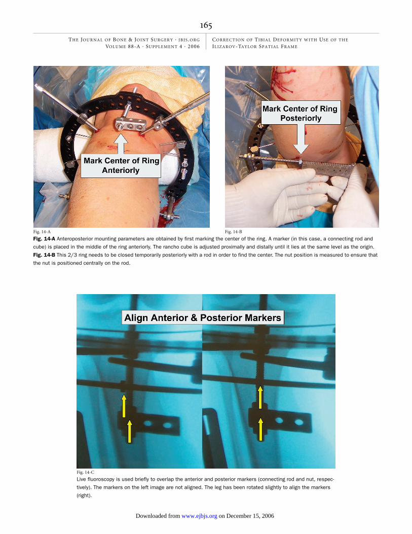
Fig. 14-A
Fig. 14-A Anteroposterior mounting parameters are obtained by first marking the center of the ring. A marker (in this case, a connecting rod and
cube) is placed in the middle of the ring anteriorly. The rancho cube is adjusted proximally and distally until it lies at the same level as the origin.
Fig. 14-B This 2/3 ring needs to be closed temporarily posteriorly with a rod in order to find the center. The nut position is measured to ensure that
the nut is positioned centrally on the rod.
Fig. 14-B
Fig. 14-C
Live fluoroscopy is used briefly to overlap the anterior and posterior markers (connecting rod and nut, respec-
tively). The markers on the left image are not aligned. The leg has been rotated slightly to align the markers
(right).
Rozbruch.fm Page 165 Monday, October 30, 2006 2:59 PM
THE JOU R N A L OF BO N E & JO I N T SU RG ER Y · JB JS .ORG
VO LUM E 88-A · SU P P L E M E N T 4 · 2006COR RE CT ION OF TIBIA L DEFOR M IT Y W IT H US E OF TH E IL I ZA ROV-TAY LOR SPA T I A L FR A M E
tinued in the immediate postoperative period to avoid mask-ing early signs of compartment syndrome, although we havenot yet had any instances of compartment syndrome with useof this technique.
Postoperative CarePatients are admitted to the hospital for two to three days.The patients receive intravenous antibiotics for twenty-fourhours and are then switched to oral antibiotics. The dress-
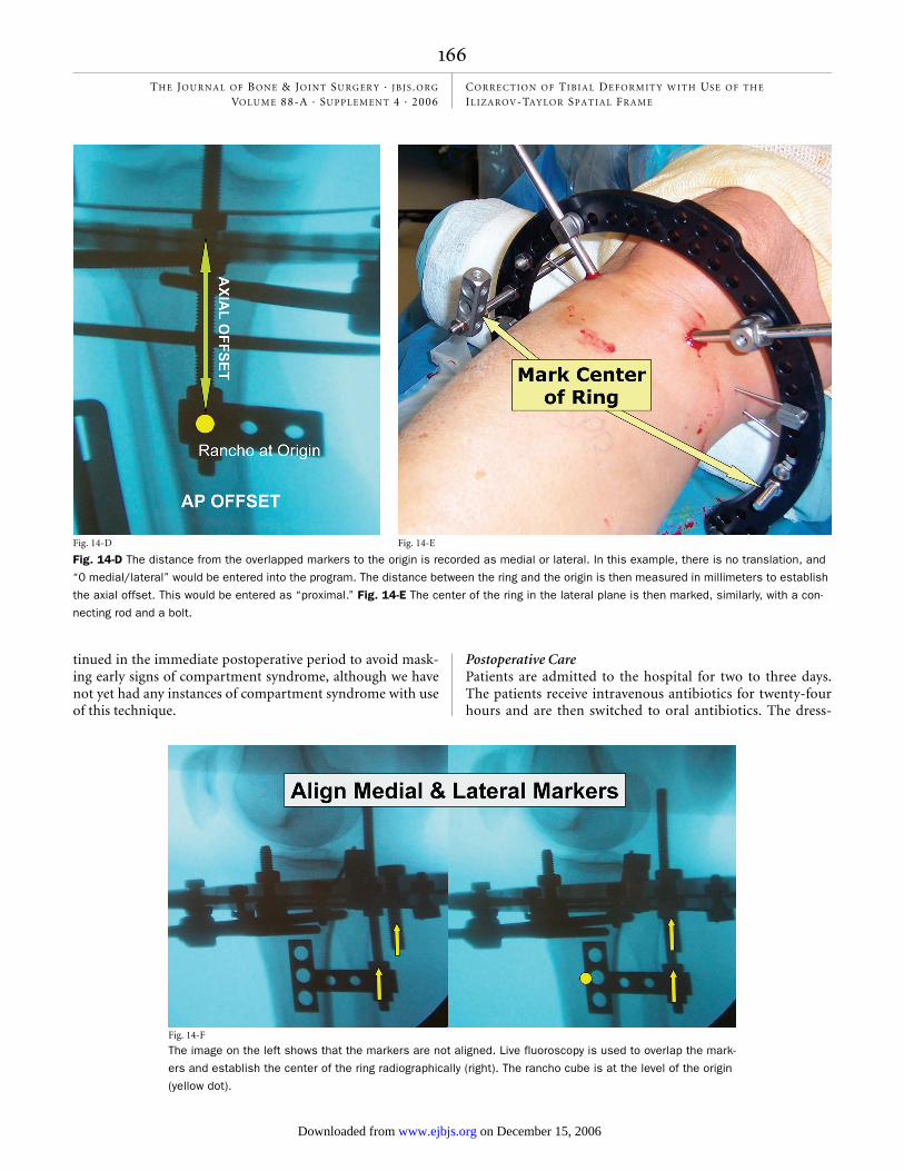
Fig. 14-D
Fig. 14-D The distance from the overlapped markers to the origin is recorded as medial or lateral. In this example, there is no translation, and
“0 medial/lateral” would be entered into the program. The distance between the ring and the origin is then measured in millimeters to establish
the axial offset. This would be entered as “proximal.” Fig. 14-E The center of the ring in the lateral plane is then marked, similarly, with a con-
necting rod and a bolt.
Fig. 14-E
Fig. 14-F
The image on the left shows that the markers are not aligned. Live fluoroscopy is used to overlap the mark-
ers and establish the center of the ring radiographically (right). The rancho cube is at the level of the origin
(yellow dot).
Rozbruch.fm Page 166 Monday, October 30, 2006 3:00 PM
THE JOU R N A L OF BO N E & JO I N T SU RG ER Y · JB JS .ORG
VO LUM E 88-A · SU P P L E M E N T 4 · 2006COR RE CT ION OF TIBIA L DEFOR M IT Y W IT H US E OF TH E IL I ZA ROV-TAY LOR SPA T I A L FR A M E
ings are removed on the second postoperative day. Nursesteach proper daily pin care with a mixture with 50% normalsaline solution and 50% hydrogen peroxide applied to thepin sites with sterile cotton swabs. Pins and wires arewrapped with Xeroform dressings at the skin level. Patientsare allowed to begin showering on the fourth postoperativeday. They are instructed to wash the frame and pin sites withantibacterial soap as an adjuvant form of pin care. Nonste-roidal anti-inflammatory medications are avoided in all osteot-omy patients for fear of adverse affects on bone formation.The patients are discharged on oral antibiotics for ten daysand oral pain medication. Recognition of early pin-tract in-fection is taught to the patient. If an infection occurs, oralantibiotics are promptly prescribed. Patients return to theoffice ten days postoperatively for suture removal, and theyare educated in how to perform strut adjustments. Patientsare seen every two weeks during this adjustment period andthen once monthly during the consolidation period. The suc-cess of any gradual correction system is founded in the abil-ity of patients to participate in their own care. Patients areresponsible for performing their own strut adjustment threetimes daily at the outset of treatment. The TSF has simplifiedthis process through color coordination and a precise num-bering system. Patients still need to be seen frequently dur-ing the adjustment period to avoid errors.
Correction of the deformity begins after a latency pe-riod of seven to ten days. The web-based Smith and Nephewprogram is used to generate a daily schedule for strut adjust-ments that the patient will perform at home. The computerrequires the input of basic information including the limblaterality, the deformity parameters (determined from pre-
Fig. 14-G
The distance from the overlapped markers to
the origin is then recorded in millimeters by
measuring the rancho cube. (An additional
rancho cube has been stacked on top to
reach the level of the origin.)
Fig. 15
This patient has one ring (a one-ring ring-block) stabilizing the proximal
bone segment and two rings (a two-ring ring-block) stabilizing the distal
segment. Proximal and distal ring-blocks are separated with TSF struts.
Rozbruch.fm Page 167 Monday, October 30, 2006 3:00 PM
THE JOU R N A L OF BO N E & JO I N T SU RG ER Y · JB JS .ORG
VO LUM E 88-A · SU P P L E M E N T 4 · 2006COR RE CT ION OF TIBIA L DEFOR M IT Y W IT H US E OF TH E IL I ZA ROV-TAY LOR SPA T I A L FR A M E
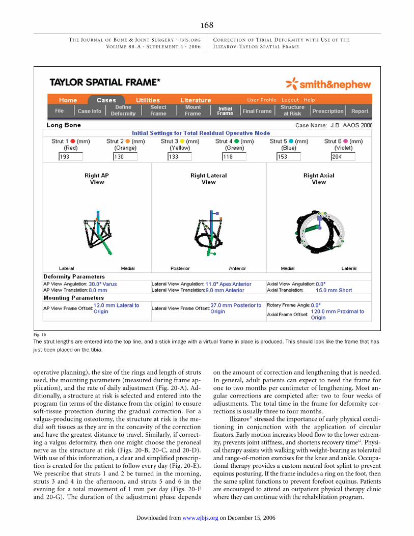
operative planning), the size of the rings and length of strutsused, the mounting parameters (measured during frame ap-plication), and the rate of daily adjustment (Fig. 20-A). Ad-ditionally, a structure at risk is selected and entered into theprogram (in terms of the distance from the origin) to ensuresoft-tissue protection during the gradual correction. For avalgus-producing osteotomy, the structure at risk is the me-dial soft tissues as they are in the concavity of the correctionand have the greatest distance to travel. Similarly, if correct-ing a valgus deformity, then one might choose the peronealnerve as the structure at risk (Figs. 20-B, 20-C, and 20-D).With use of this information, a clear and simplified prescrip-tion is created for the patient to follow every day (Fig. 20-E).We prescribe that struts 1 and 2 be turned in the morning,struts 3 and 4 in the afternoon, and struts 5 and 6 in theevening for a total movement of 1 mm per day (Figs. 20-Fand 20-G). The duration of the adjustment phase depends
on the amount of correction and lengthening that is needed.In general, adult patients can expect to need the frame forone to two months per centimeter of lengthening. Most an-gular corrections are completed after two to four weeks ofadjustments. The total time in the frame for deformity cor-rections is usually three to four months.
Ilizarov11 stressed the importance of early physical condi-tioning in conjunction with the application of circularfixators. Early motion increases blood flow to the lower extrem-ity, prevents joint stiffness, and shortens recovery time12. Physi-cal therapy assists with walking with weight-bearing as toleratedand range-of-motion exercises for the knee and ankle. Occupa-tional therapy provides a custom neutral foot splint to preventequinus posturing. If the frame includes a ring on the foot, thenthe same splint functions to prevent forefoot equinus. Patientsare encouraged to attend an outpatient physical therapy clinicwhere they can continue with the rehabilitation program.
Fig. 16
The strut lengths are entered into the top line, and a stick image with a virtual frame in place is produced. This should look like the frame that has
just been placed on the tibia.
Rozbruch.fm Page 168 Monday, October 30, 2006 3:00 PM
THE JOU R N A L OF BO N E & JO I N T SU RG ER Y · JB JS .ORG
VO LUM E 88-A · SU P P L E M E N T 4 · 2006COR RE CT ION OF TIBIA L DEFOR M IT Y W IT H US E OF TH E IL I ZA ROV-TAY LOR SPA T I A L FR A M E
Fixator RemovalFixators are removed when the patients are walking withoutpain or the use of an assistive device and when callus is seenon three cortices around the osteotomy site. The timing var-ies tremendously depending on what goals are being accom-plished. We prefer to remove the frames in the operatingroom, particularly since the removal of hydroxyapatite-coated pins can be uncomfortable and bloody. We choose tocuret all half-pin sites in an effort to keep all pin tracts cleanfor possible future use of internal implants. Transfixion wiresites are not débrided unless there is concern over a specificsite. At the time of frame removal, osseous union and matu-ration of the regenerated bone may be evaluated with a stresstest under c-arm fluoroscopy. The struts are removed and
the rings are manually compressed and distracted to look formotion at the osteotomy site. A lack of consolidation re-quires replacement of the struts and prolonging the time inthe frame. Once the fixator is removed, the patients are man-aged with a hinged knee brace with full motion or a short legcast depending on the site of the osteotomy and clinicalneeds. They are allowed partial weight-bearing for two weeksand then progress to full weight-bearing thereafter.
Fig. 17-A
This maximal dorsiflexion radiograph demonstrates a patient with a
recurvatum deformity of the distal aspect of the tibia and a con-
comitant equinus contracture of the ankle.
Fig. 17-C
Figs. 17-B and 17-C Simultaneous gradual correction of the os-
seous deformity through a distal tibial osteotomy and correction of
the equinus contracture through gradual distraction of the posterior
capsule and heel cord. Photographs made before (Fig. 17-B) and af-
ter (Fig. 17-C) correction, with the leg still in the frame. The middle
ring has essentially tilted the distal end of the tibia into normal
alignment.
Fig. 17-B
Rozbruch.fm Page 169 Tuesday, November 7, 2006 11:17 AM
THE JOU R N A L OF BO N E & JO I N T SU RG ER Y · JB JS .ORG
VO LUM E 88-A · SU P P L E M E N T 4 · 2006COR RE CT ION OF TIBIA L DEFOR M IT Y W IT H US E OF TH E IL I ZA ROV-TAY LOR SPA T I A L FR A M E
Critical ConceptsIndications:• The Ilizarov-TSF is indicated for any tibial deformity cor-
rection. Although other fixation techniques have been suc-cessful at stabilizing deformities once they have beencorrected, the TSF has the distinct advantage of providing ameans of correcting the deformity as well as stabilizing thebone after the deformity has been corrected. This allows forgradual correction of deformities, which has important ad-vantages over acute correction, including a lower risk ofneurovascular and soft-tissue compromise, preservation ofbone stock (by not having to remove a wedge of bone), andprecise control over the final alignment. Patients with largedeformities are especially well served with this treatmentapproach.
• Proximal tibial osteotomy for the unloading of unicompart-mental knee arthritis can be performed gradually with preci-sion control over the final location of the mechanical axis toachieve ideal overcorrection4.
• When deep infection is suspected, the temporary and percu-
taneous nature of the Ilizarov method without internal hard-ware is useful for the treatment of infection and deformitycorrection.
• For the patients with tibial shortening, the option of a si-multaneous lengthening is made possible with use of theIlizarov-TSF.
Fig. 19
Rotational osteoclasis is used to ensure a complete osteotomy. The
distal end of the leg is externally rotated to avoid stretching of the
common peroneal nerve.
Fig. 18
A narrow osteotome is used to create a percutaneous osteotomy.
Fig. 17-D
Final radiographs show correction of both deformities. Despite the
presence of ankle arthritis, this realignment procedure produced sub-
stantial pain relief. If needed, a simple staged ankle arthrodesis could
now be performed.
Rozbruch.fm Page 170 Monday, October 30, 2006 3:00 PM
THE JOU R N A L OF BO N E & JO I N T SU RG ER Y · JB JS .ORG
VO LUM E 88-A · SU P P L E M E N T 4 · 2006COR RE CT ION OF TIBIA L DEFOR M IT Y W IT H US E OF TH E IL I ZA ROV-TAY LOR SPA T I A L FR A M E
• When a poor soft-tissue envelope is of concern, as is oftenthe case after severe trauma with deformity from osseousmalunion, large dissections can often be avoided by imple-menting a percutaneous osteotomy and external fixation.
• When the true axis of a deformity lies in an oblique plane, cor-rection of that deformity can be very challenging with conven-tional fixation methods. The TSF computer program hasgreatly simplified the planning and execution of the correctionof these complex deformities with excellent results.
• When early mobilization is of primary concern, as is oftenthe case with large patients who need to be able to bearweight immediately for balance purposes, the TSF providesenough stability to support early weight-bearing and range-of-motion exercises of the adjacent joints.
• Multiple-level corrections can be accomplished with this ap-proach. The Ilizarov-TSF can be used in a modular fashionto simultaneously address multiple levels of deformity in-cluding contractures of adjacent joints.
Contraindications:• Older patients who have no support network and no ability
to care for themselves are not ideal candidates, although
nursing-home staff can be instructed to perform frame ad-justments and pin care successfully.
• Patients who have severe or uncontrolled psychiatric diseaseare historically not good candidates for external fixation.
• In the case of limb salvage, patients need to be strongly com-mitted and well educated as to the emotional and time com-mitment needed for Ilizarov limb reconstruction. Amputationreconstruction may be a better option for some patients evenif limb salvage is possible.
Pitfalls:• An incomplete osteotomy often leads to a premature consoli-
dation. A circumferential division of the tibial cortex may betested by rotating the proximal and distal rings in oppositedirections and witnessing translational motion through theosteotomy site. Other methods, including acute distractionand angulation at the osteotomy site, have been described,but these techniques are more disruptive to the periosteumand are not recommended.
• Proper technique for pin and wire insertion, including strictadherence to anatomic safe zones, is paramount to the suc-cess of this method. Great care must be taken to avoid ther-mal necrosis, which leads to loosening of fixation, pininfection, and patient discomfort. Predrilling all half-pins,hand insertion of pins, frequent pausing during wire inser-tion, and lowering of the tourniquet are all methods for re-ducing the chances of burning the bone.
• Choosing the osteotomy site requires careful consideration oftwo independent goals: (1) maximizing the healing potentialof the osteotomy and (2) reestablishing proper alignment, notnecessarily an anatomic reduction of the deformity. Often cor-recting a malunion deformity at its center of rotation of angu-lation would require an osteotomy through an area of scleroticbone with poor osteogenic potential. A good solution in-volves cutting the bone distal to the center of rotation of angu-lation, through metaphyseal bone, which requires osseoustranslation but offers predictable healing.
Corresponding author:S. Robert Rozbruch, MDInstitute for Limb Lengthening and Reconstruction, The Hospital for Special Surgery, 535 East 70th Street, New York, NY 10021. E-mail ad-dress: [email protected]
The authors did not receive grants or outside funding in support of their research for or preparation of this manuscript. They did not re-ceive payments or other benefits or a commitment or agreement to provide such benefits from a commercial entity. No commercial entity paid or directed, or agreed to pay or direct, any benefits to any re-search fund, foundation, educational institution, or other charitable or nonprofit organization with which the authors are affiliated or associated.
doi:10.2106/JBJS.F.00745
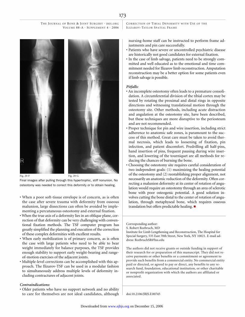
Fig. 20-F
Final images after pulling through this hypertrophic, stiff nonunion. No
osteotomy was needed to correct this deformity or to obtain healing.
Fig. 20-G
Rozbruch.fm Page 173 Tuesday, November 7, 2006 11:13 AM
THE JOU R N A L OF BO N E & JO I N T SU RG ER Y · JB JS .ORG
VO LUM E 88-A · SU P P L E M E N T 4 · 2006COR RE CT ION OF TIBIA L DEFOR M IT Y W IT H US E OF TH E IL I ZA ROV-TAY LOR SPA T I A L FR A M E
References
1. Rozbruch SR, Herzenberg JE, Tetsworth K, Tuten HR, Paley D. Distraction os-teogenesis for nonunion after high tibial osteotomy. Clin Orthop Relat Res. 2002;394:227-35.
2. Rozbruch SR, Helfet DL, Blyakher A. Distraction of hypertrophic nonunion of tibia with deformity using Ilizarov/Taylor Spatial Frame. Report of two cases. Arch Orthop Trauma Surg. 2002;122:295-8.
3. Rozbruch SR. Posttraumatic reconstruction of the ankle using the Ilizarov method. HSSJ. 2005;1:68-88.
4. Fragomen AT, Ilizarov S, Blyakher A, Rozbruch SR. Proximal tibial osteotomy for medial compartment osteoarthritis of the knee using the Ilizarov Taylor Spatial Frame. Tech Knee Surg. 2005;4:173-85.
5. Feldman DS, Shin SS, Maden S, Koval KJ. Correction of tibial malunion and nonunion with six-axis analysis deformity correction using the Taylor Spatial Frame. J Orthop Trauma. 2003;17:549-54.
6. Sen C, Kocaoglu M, Eralp L. The advantages of circular external fixation used in high tibial osteotomy (average 6 years follow-up). Knee Surg Sports Traumatol Arthrosc. 2003;11:139-44.
7. Paley D, Tetsworth K. Mechanical axis deviation of the lower limbs. Preopera-tive planning of uniapical angular deformities of the tibia or femur. Clin Orthop Relat Res. 1992;280:48-64.
8. Paley D. Principles of deformity correction. New York: Springer; 2002. p 479-507.
9. Reid JS, Van Slyke MA, Moulton MJ, Mann TA. Safe placement of proximal tib-ial transfixation wires with respect to intracapsular penetration. J Orthop Trauma. 2001;15:10-7.
10. Savarino L, Stea S, Granchi D, Donati ME, Cervellati M, Moroni A, Paganetto G, Pizzoferrato A. X-Ray diffraction of bone at the interface with hydroxyapatite-coated versus uncoated metal implants. J Mater Sci Mater Med. 1998;9:109-15.
11. Ilizarov GA. The apparatus: components and biomechanical principles of ap-plication. In: Transosseus osteosynthesis: theoretical and clinical aspects of re-generation and growth of tissue. Berlin: Springer; 1992. p 63-136.
12. Ilizarov GA. The influence of blood supply and loading upon the shape forming processes in bones and joints. In: Transosseus osteosynthesis: theoretical and clin-ical aspects of regeneration and growth of tissue. Berlin: Springer; 1992. p 257-78.
Rozbruch.fm Page 174 Monday, October 30, 2006 3:00 PM