7
www.jfc.ie CorriPipe™ Technical Specification
www.jfc.ie
CorriPipe™Technical Specification

1 www.jfc.ie
1. IntroductionCorriPipe™ is a twin wall high density polyethylenepipemanufactured from a blended black polyethyleneby a twin extrusion process.
Two high density polyethylene walls are extrudedsimultaneously, one inside the other, and heat-weldedtogether in one continuous process. The outer wall iscorrugated and the inner wall is smooth finished.
It is a combination of the corrugations, and the heat-welding of the two walls, that give CorriPipe™ itsexcellent structural strength while its smooth innerwall ensures increased flow capacity.
Its applications include surface and storm waterdrainage in civil engineering, construction, sportsamenity, agricultural and other sub-soil applications.
CorriPipe™ is fully BBA (British Board of Agrément)approved and HAPAS (Highways Agency ProductApproval Scheme) certified.
2. DimensionsCorriPipe™ comes in a complete range between 100mand 600mm and is available in either carrier of filterpipe. CorriPipe™ also has a complete range of fittingsand junctions as detailed below.
Note: CorriPipe also available in various perforationspecification. e.g. half perforated, double perforated.
Note: Larger fitting sizes fabricated on request
CorriPipe™ Technical Specification
Figure 1. – CorriPipe™
Nominal Size Inside Diameter Outside Diameter Pipe Length (mm) (mm) (mm) (m)
9494 110 6150 149 176 6225 221 265 6300 295 354 6375 370 426 6450 445 512 6600 590 680 6
Table 1. – CorriPipe™ Dimensions
Nominal Size No. of slots Nom. Slot Pefrorated Area (mm) per alternate dwell Width (mm) (mm /m)94 4 1.5 7920
150 4 2 6120225 4 2 4680300 4 2 5120375 3 3 4263450 3 3 4024600 3 3 4942
Table 2. – Perforated Pipe Detail
Nominal Size Code Fitting Type(mm)150 150TB30 30° Bend150 150TB45 45° Bend150 150TB90 90° Bend150 150TT90 Equal Tee150 150TY45 Equal Wye150 150SWSTT90 Single Wall Tee
225 225TB30 30° Bend225 225TB45 45° Bend225 225TB90 90° Bend225 225TT90 Equal Tee225 225TY45 Equal Wye225 225/150TT90 Unequal Tee 150225 225/150TY45 Unequal Wye 150225 225SWSTT90 Single Wall Tee
300 300TB30 30° Bend300 300TB45 45° Bend300 300TB90 90° Bend300 300TT90 Equal Tee300 300TY45 Equal Wye300 300/150TT90 Unequal Tee 150300 300/150TY45 Unequal Wye 150300 300/225TT90 Unequal Tee 225300 300/225TY45 Unequal Wye 225300 300SWSTT90 Single Wall Tee
Table 3. – CorriPipe™ Fittings

2www.jfc.ie
3. Hydraulic CapacityThere are two main formulas used in hydrauliccalculations of gravity flow pipelines – Manning’s andColebrook-White:
Manning’sManning’s is themost popular equation for stormwaterdesign because it is simple to apply and it generallyprovides an acceptable level of accuracy.
Colebrook-WhiteA more accurate method for calculations involvingFRC™ pipes is to utilize the Colebrook-White formula.The Colebrook-White design chart for FRC™ shouldallow quick and easy estimates without involvedcalculations.
Q =Water Discharge [m3/s]
n = Manning’s roughness factor [s/m1/3]]
A = Cross-sectional area [m2]
R = Hydraulic radius [m]
S = SurfaceWater Slope [m/m]
V = Velocity (m/s)
S = Hydraulic gradient (m/m)
k = Hydraulic roughness (m)
R = Hydraulic radius = D/4 (m)
D = Pipe internal diameter (m)
g = Gravitational acceleration (m/s2)
v = Kinematic viscosity of water (m2/s)
4. Cover DepthsMinimum Cover DepthsJFCManufacturing Limited recommends the followingminimum cover depths.
• 0.6m for non trafficked green areas
• 0.9m to finished surface for trafficked areas notsubject to Highways Agency or National RoadsAuthority requirements
• 1.2m to finished surface for trafficked areassubject to Highways Agency or National RoadsAuthority requirements.
In certain circumstances lower minimum cover levelsmay be allowed. e.g. installation with rigid pavement,concrete surround etc. Please contact JFC for moreinformation.
Maximum Cover DepthsThe maximum cover depth for CorriPipe™ is normallybetween 6-10 meters when installed in accordancewith series 500 of the MCDHWVolume 1 as detailed inthe CorriPipe™ BBA certificate.
The actual maximum allowable cover level isdependent on the following installation parametersand is often well in excess of 6-10 meters:
• The native soil stiffness
• The pipe bed and surround stiffness
• The size of the trench
• The density of the overburden
• Hydrostatic loading
• Factor of Safety
• Maximum allowable deflection limit
For specific site conditions JFC can calculate themaximum pipe deflection based on the aboveparameters. Contact JFC for more details.
CorriPipe™ Technical Specification

3 www.jfc.ie
4. InstallationJFC CorriPipe is to be installed in accordance with thefollowing national guidelines. In countries outside thatspecified contact JFC for more details.
IrelandThe Manual of Contract Documents for Road Works,Volume 1 series 500, clauses 503 and 505 as publishedby the NRA.
United KingdomThe Manual of Contract Documents for HighwayWorks, Volume 1 series 500, clauses 503, 505, 518.7 and518.8 as published by the Highways Agency
Trench PreparationThe trench width is generally between OD+300mmand OD+600mm but larger trenches are permissible.The trench should provide for a minimum of 150mmpipe bed and local soft spots must be removed andreplaced with hardcore. The pipe must sit evenly onthe bed and must be free of voids under the pipe. Thetrench should not be excavated too far in advance ofpipe installation. All trenches are to be excavated inaccordancewith national health and safety regulationsand local building regulations.
SidefillCorriPipe™ is to backfilled as described in theMCDHW,Volume 1, Series 500. Sidefill material is dependent onspecification but is normally a well graded granularmaterial or small single size aggregate. The pipesurround material must fully support the pipe.Compaction may be required depending on groundconditions and sidefill material used. If compaction isrequired the compaction equipment must not comein contact with the pipe. The sidefill material shouldextend to 100mm over the crown of the pipe.
BackfillBackfill is to continue to a minimum of 300mm abovethe crown of the pipe with suitable material as perspecification. The material should be free of any stoneparticles greater than 50mm. Compaction should notbe carried out until a minimum cover of 300mm isachieved. Compaction equipment should be sized soas not to exert any undue stress in the pipe. Furtherbackfill to the required level should be carried out inlayer no greater than 300mm.
A = Backfill
B = Sidefill
C = Bed
D = Earth
OD = Outside Diameter of Pipe
CorriPipe™ Technical Specification
Figure 2. – Typical Installation Details
4www.jfc.ie
5. JointingCorriPipe™ is manufactured in 6 meter lengths and isjoined with straight couplers or suitable fittings (e.g.tees, wyes, bends etc.)
CorriPipe™ provides a fully watertight seal wheninstalled in accordance with JFC recommendations.
Leak tightness is in accordance with BS EN 1277:1997.The maximum permitted angular deflection is 2°.
Rubber seals used in watertight applications are inaccordance with BS EN 681-1:1996
JFC recommends the following procedure for joiningCorriPipe™ and associated fittings / couplers.
• Cut the pipe to the require length with aconventional handsaw.
• Clean the end of the pipe and accompanyingcoupler / fitting.
• Install a ring seal in the first dwell of the pipe forwatertight joints.
• Ring seals are bi directional
• Lubricate the ring seal and accompanying coupler/ fitting.
• Offer the fitting / coupler up to the pipe
• Lever the fitting / coupler onto the pipe with apiece of timber ensuring not to damage the pipe.Larger pipes may require mechanical assistance.
• Ensure the fitting / coupler is butted fully againstthe pipe.
• For joining pipes to the opposite side of the fitting/ coupler follow the same steps as outlined above.
6. Pressure TestingThere are two methods of pressure testing, the air testmethod and the water test method. The mostcommon method is the air test method and the testprocedure is outlined below.
• Block the ends of the pipe / fitting with a suitableexpanding stopper, ensuring both plug and pipeare cleaned prior to fitting.
• Fill a U-Tube manometer with water to the correctlevel, ensuring there are no trapped air bubbles inthe water.
• Connect the u-tube to the fitting on theexpandable stopper.
• Increase the pressure in the pipe until a head ofwater of 100mm is reached.
• Allow the pressure to stabilise for a number ofminutes, increasing the pressure if it drops.
• Record the pressure drop over a five minuteperiod.
• To pass the test the pressure should not dropbelow a 75mm head of water.
Note: Temperature has a critical effect on the test, a 1°C changein air temperature inside the pipe is sufficient for the test to fail.
CorriPipe™ Technical Specification
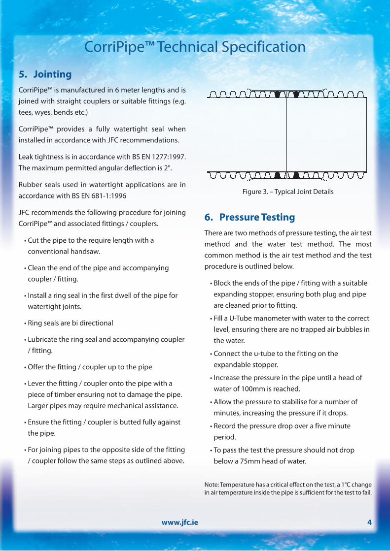
Figure 3. – Typical Joint Details

5 www.jfc.ie
6. Transportation, Handling andStorage
GeneralHandling should be done carefully and in accordancewith national health and safety guidelines. Draggingof pipes and fittingsmust be avoided. HDPE pipes andfittings become slippery in wet or in cold weather andextra precautions may be necessary.
Pipes up to 450mm in size are palletised with woodenframes and steel straps. 600mm pipes are generallysteel banded in two’s but can also be supplied loose.
StorageAll materials should be carefully inspected at the timeof delivery and any defects should be notified andreported immediately. All pipe stacks should be madeon firm, flat ground to support theweight of the pipesand lifting equipment. For safety and Pipes and fittingsshould be transported and stored in their packaging.
Delivery vehicles should be provided with a clean, flatbed, free from sharp objects. Care must be taken toprevent slippage or excessive bowing of the pipes. Tiethe loadwell to prevent rubbing. Use nylon straps, notchains or ropes.
The stacking height for pipes should be limited to notmore than 3 meters. Pipes should be not be stored inopen areas subject to high winds.
It is recommended that CorriPipe™ is not stored indirect sunlight for more than 3 months.
CorriPipe™ Technical Specification
Nominal Size Number of Pipes(mm) per Pallet100 100150 33225 14300 8375 5450 4600 2 / steel banded
Table 4. – CorriPipe™ Pallet Quantities
It is believed that the information and dimensions given in this publication are correct.The products marketed by the company are, however subject to continuous development and the company,therefore reserves the right to alter information without notice. Copyright JFC, Rev 001 Feb 2009.
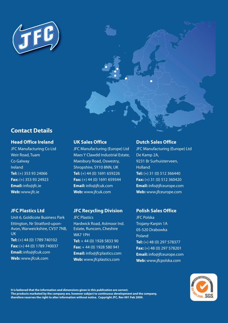
Contact Details
Head Office IrelandJFC Manufacturing Co LtdWeir Road, TuamCo GalwayIrelandTel: (+) 353 93 24066Fax: (+) 353 93 24923Email: [email protected]:www.jfc.ie
JFC Plastics LtdUnit 6, Goldicote Business ParkEttington, Nr Stratford-upon-Avon,Warweickshire, CV37 7NB,UKTel: (+) 44 (0) 1789 740102Fax: (+) 44 (0) 1789 740037Email: [email protected]:www.jfcuk.com
UK Sales OfficeJFC Manufacturing (Europe) LtdMaes Y Clawdd Industrial Estate,Maesbury Road, Oswestry,Shropshire, SY10 8NN, UKTel: (+) 44 (0) 1691 659226Fax: (+) 44 (0) 1691 659344Email: [email protected]:www.jfcuk.com
JFC Recycling DivisionJFC PlasticsHardwick Road, Astmoor Ind.Estate, Runcorn, CheshireWA7 1PHTel: + 44 (0) 1928 5833 90Fax: + 44 (0) 1928 580 941Email: [email protected]:www.jfcplastics.com
Dutch Sales OfficeJFC Manufacturing (Europe) LtdDe Kamp 2A,9231 Br Surhuisterveen,HollandTel: (+) 31 (0) 512 366440Fax: (+) 31 (0) 512 360420Email: [email protected]:www.jfceurope.com
Polish Sales OfficeJFC PolskaTrojany-Karpin 1A05-520 DrabowkaPolandTel: (+) 48 (0) 297 578377Fax: (+) 48 (0) 297 578201Email: [email protected]:www.jfcpolska.com


![Rainbow Heart - artecy.com · 7777777 777777777 7777777777777 ooooooo 77777 7777777 7777777777777 oooooo]]]]] ddd ddd ddd ddd ddd ™™™™™™™™™™™ ™™™™™™™™™™™™™™™™™](https://static.documents.pub/doc/80x56/5f4a4ec8ec2fea16bc048a6a/rainbow-heart-7777777-777777777-7777777777777-ooooooo-77777-7777777-7777777777777.jpg)


