438
CorsairHMI Manual

CorsairHMI Manual

2 | P a g e
6/27/2020
Contents Overview ..................................................................................................................................................... 16
Features ...................................................................................................................................................... 16
Alarming .................................................................................................................................................. 16
Sounds ..................................................................................................................................................... 16
Trending .................................................................................................................................................. 16
Data Logs ................................................................................................................................................. 16
Plotted Data ............................................................................................................................................ 17
TBT .......................................................................................................................................................... 17
Email ........................................................................................................................................................ 17
Event Logging .......................................................................................................................................... 17
Corrections .............................................................................................................................................. 21
Architectures ............................................................................................................................................... 21
MBHR ...................................................................................................................................................... 21
Plantwide Interface ................................................................................................................................. 23
Multiple Models ...................................................................................................................................... 24
Enterprise Interface ................................................................................................................................ 24
Web ......................................................................................................................................................... 24
Serial Terminal ........................................................................................................................................ 24
Licensing ...................................................................................................................................................... 25
Strategic Fit ................................................................................................................................................. 25
Linux ........................................................................................................................................................ 25
Education ................................................................................................................................................ 26
Future Directions ........................................................................................................................................ 27
Distributed Hosting ................................................................................................................................. 27
Streaming Serial ...................................................................................................................................... 31
Comparison of Corsair Viewing Options ..................................................................................................... 32

3 | P a g e
Operating the Corsair Interface .................................................................................................................. 39
Screens ........................................................................................................................................................ 39
Sheets .......................................................................................................................................................... 39
Operating a Setpoints Sheet ....................................................................................................................... 41
A Reasons Sheet .......................................................................................................................................... 42
Alarms ......................................................................................................................................................... 42
I/O Modules ................................................................................................................................................ 43
Listed Drawings ........................................................................................................................................... 43
Clock Set ...................................................................................................................................................... 43
Battery Low ................................................................................................................................................. 44
Quick Trends ............................................................................................................................................... 45
Trends ......................................................................................................................................................... 45
Log Plotted Data .......................................................................................................................................... 46
History ......................................................................................................................................................... 48
Turn-Back-Time ........................................................................................................................................... 49
Event Logging .............................................................................................................................................. 50
Report Forms .............................................................................................................................................. 50
Web View .................................................................................................................................................... 51
Multiple Models .......................................................................................................................................... 51
Touchscreen Cleaning ................................................................................................................................. 51
Development............................................................................................................................................... 51
Installation .................................................................................................................................................. 51
Development Basics .................................................................................................................................... 56
Databases .................................................................................................................................................... 59
Sessions ................................................................................................................................................... 59
Drivers ..................................................................................................................................................... 63
Data Sources ........................................................................................................................................... 65
Register Blocks ........................................................................................................................................ 67
Tags ......................................................................................................................................................... 68
Tag Types ............................................................................................................................................ 68
Tag Configuration ................................................................................................................................ 69
Tag Data Formats ................................................................................................................................ 72

4 | P a g e
Strings ................................................................................................................................................. 74
Alarms ..................................................................................................................................................... 76
Calls ......................................................................................................................................................... 79
Icons ........................................................................................................................................................ 80
Drawings ................................................................................................................................................. 81
Screens .................................................................................................................................................... 82
Sounds ..................................................................................................................................................... 83
Sheets ...................................................................................................................................................... 85
Trends ..................................................................................................................................................... 85
Scripts ...................................................................................................................................................... 86
Data Logs ................................................................................................................................................. 87
Ethernet Objects ..................................................................................................................................... 94
SQL Paths ................................................................................................................................................ 94
FTP Paths ................................................................................................................................................. 95
Driver Paths ............................................................................................................................................. 96
Local and Global Database Views ........................................................................................................... 96
Creating Graphics ........................................................................................................................................ 97
Placement Types ..................................................................................................................................... 99
Address ............................................................................................................................................. 100
Arc ..................................................................................................................................................... 100
Bar Graph .......................................................................................................................................... 101
Checkbox ........................................................................................................................................... 102
Corner ............................................................................................................................................... 103
Drawing ............................................................................................................................................. 103
Ellipse ................................................................................................................................................ 104
Frame ................................................................................................................................................ 104
Icon .................................................................................................................................................... 105
Key ..................................................................................................................................................... 105
Line .................................................................................................................................................... 106
Picture ............................................................................................................................................... 107
Pipe ................................................................................................................................................... 108
Point Name ....................................................................................................................................... 108

5 | P a g e
Polygon.............................................................................................................................................. 108
Rectangle........................................................................................................................................... 109
Rounded Rectangle ........................................................................................................................... 110
Spline ................................................................................................................................................. 111
Tank ................................................................................................................................................... 112
Text ................................................................................................................................................... 113
Trend ................................................................................................................................................. 113
Value ................................................................................................................................................. 114
Placement Actions ................................................................................................................................ 115
Alarm Action ..................................................................................................................................... 115
Call Action ......................................................................................................................................... 115
Display Action ................................................................................................................................... 115
Entry Action ....................................................................................................................................... 115
I/O Jump Action ................................................................................................................................ 115
Log Jump Action ................................................................................................................................ 115
Source Comms Action ....................................................................................................................... 115
Quick Trend Action ............................................................................................................................ 116
Screen Jump Action ........................................................................................................................... 116
Sheet Jump Action ............................................................................................................................ 116
Task Action ........................................................................................................................................ 116
Trend Jump Action ............................................................................................................................ 116
Door Action ....................................................................................................................................... 116
Door Command Action...................................................................................................................... 117
Developing User Sheets ............................................................................................................................ 117
Creating I/O Modules ................................................................................................................................ 120
Developing with Corsair Blocks ................................................................................................................. 120
The Corsair Select and Replace System .................................................................................................... 122
Database Record Import and Export ........................................................................................................ 126
CSV Data Import ........................................................................................................................................ 128
DXF Import ................................................................................................................................................ 131
Corsair Micro-CAPs ................................................................................................................................... 134
Computer Configuration ........................................................................................................................... 136

6 | P a g e
Model List Group .................................................................................................................................. 137
Sessions Group ...................................................................................................................................... 139
Desktop Group ...................................................................................................................................... 139
Comms Ports Group .............................................................................................................................. 140
Sounds Group ........................................................................................................................................ 141
Startup Options Group .......................................................................................................................... 141
Startup Levels Group............................................................................................................................. 141
Startup Delays Group ............................................................................................................................ 142
Reports Printing Group ......................................................................................................................... 142
Reports Fonts Group ............................................................................................................................. 143
Reports SQL Group ................................................................................................................................ 143
Web Group ............................................................................................................................................ 144
Menus Group ........................................................................................................................................ 145
Email Group .......................................................................................................................................... 145
My IP Group .......................................................................................................................................... 146
Passwords Group .................................................................................................................................. 146
Users Group .......................................................................................................................................... 146
Scramble Group .................................................................................................................................... 147
Style Group ........................................................................................................................................... 148
MBHR Group ......................................................................................................................................... 148
Serial Group .......................................................................................................................................... 149
Help Files Group .................................................................................................................................... 150
EDS Group ............................................................................................................................................. 151
Shutdown Group ................................................................................................................................... 152
Developer Preferences.............................................................................................................................. 152
Printing the Manual .................................................................................................................................. 154
The My IP System ...................................................................................................................................... 157
New Versions via Email ............................................................................................................................. 160
Using CorsairHMI with Linux ..................................................................................................................... 160
CorsairHMI System Design ........................................................................................................................ 161
PLC Addressing .......................................................................................................................................... 161
Register Monitors ................................................................................................................................. 161

7 | P a g e
Modbus Family Addressing ................................................................................................................... 162
Allen-Bradley DF1 Family Addressing ................................................................................................... 164
Reserved Addresses .............................................................................................................................. 165
Aux Databases ........................................................................................................................................... 165
Driver Types .............................................................................................................................................. 166
ABCLX – Allen-Bradley Logix ................................................................................................................. 166
ActiveX – ActiveX Control Interface ...................................................................................................... 166
ANSITERM – ANSI Terminal Text Display .............................................................................................. 166
ASCII Read – Unsolicited – Serial Port ................................................................................................... 166
ASCII Write – Triggered Output – Serial Port ........................................................................................ 183
BACnet – Building Automation and Control ......................................................................................... 183
.............................................................................................................................................................. 184
.............................................................................................................................................................. 186
Operation with only reading the present-value property .................................................................... 187
Operation with reading the present-value and secured-status properties .......................................... 188
Centurion – Response Technologies Centurion Elite ............................................................................ 189
DIGIFORT – Digifort VMS ...................................................................................................................... 189
Digifort Quick Start .......................................................................................................................... 190
Digifort Driver Documentation ...................................................................................................... 192
DXI – Harding Instruments DXI Intercom .............................................................................................. 202
DXL – Harding Instruments DXL Intercom ............................................................................................ 202
EIP Devices ............................................................................................................................................ 206
EIP ID – ID Readers ................................................................................................................................ 206
Email Command .................................................................................................................................... 206
Ewert CAN – CANbus ............................................................................................................................ 206
GESRTP – General Electric Series 90 TCP/IP.......................................................................................... 211
GPS – NMEA Compatible GPS Serial ..................................................................................................... 211
InterModel – Inter-Model Data Exchange ............................................................................................ 211
Linux GPIO ............................................................................................................................................. 212
Linux I2C ................................................................................................................................................ 213
MBAP – Modbus Ethernet Application Protocol .................................................................................. 217
MBASC – Modbus ASCII Serial .............................................................................................................. 217

8 | P a g e
MBEMD – Modbus Ethernet Multi-Drop .............................................................................................. 218
MBEMDE – Modbus Ethernet Multi-Drop Extended ............................................................................ 218
MBMM – Modbus Memory Map .......................................................................................................... 218
MBPUSH – Modbus TCP Push ............................................................................................................... 219
MBRTU – Modbus RTU Serial ................................................................................................................ 222
MBTIMING – Modbus Serial Timing ...................................................................................................... 222
NetScan – Network Scanning ................................................................................................................ 222
ODB2 – Simplified Vehicle Interface ..................................................................................................... 222
PCCC CLX – Allen-Bradley DF1 over CIP ................................................................................................ 222
PCCC SLC – Allen-Bradley DF1 over CIP ................................................................................................ 223
Pelco Video Switching ........................................................................................................................... 223
PLC5Enet – Allen-Bradley PLC-5 Ethernet ............................................................................................. 227
Honeywell Pro-Watch ........................................................................................................................... 227
S4100 – Simplex 4100 ........................................................................................................................... 235
Serial Stream – Receiving data from a port .......................................................................................... 236
Siemens S7 – S7 PLC over Ethernet ...................................................................................................... 237
SQL – Database Access .......................................................................................................................... 237
String Match – ASCII Input .................................................................................................................... 238
Telecor T3 – T3-SC Intercom ................................................................................................................. 242
VICON – Vicon Video Switching ............................................................................................................ 242
Placement Tasks ........................................................................................................................................ 243
Add Value .............................................................................................................................................. 243
Alarm List .............................................................................................................................................. 243
Block Monitor........................................................................................................................................ 243
Block Setup............................................................................................................................................ 243
Change Operator Levels ........................................................................................................................ 244
Change Password .................................................................................................................................. 244
Change PIN ............................................................................................................................................ 244
Clean Screen.......................................................................................................................................... 244
Close Window ....................................................................................................................................... 244
Code Entry Pad ...................................................................................................................................... 244
Create Note ........................................................................................................................................... 244

9 | P a g e
CSV File .................................................................................................................................................. 244
CSV File Directory .................................................................................................................................. 244
Decrement ............................................................................................................................................ 244
Do Global Report ................................................................................................................................... 245
Do Local Report ..................................................................................................................................... 245
Email Contact List .................................................................................................................................. 245
Increment .............................................................................................................................................. 245
Global Report Window.......................................................................................................................... 245
Local Report Window ............................................................................................................................ 245
Log Events ............................................................................................................................................. 245
Log Off ................................................................................................................................................... 245
Log On ................................................................................................................................................... 245
Model Selector ...................................................................................................................................... 246
Monitor Registers ................................................................................................................................. 246
Name Finder .......................................................................................................................................... 246
Open File ............................................................................................................................................... 246
Print Screen - Default Printer ................................................................................................................ 246
Print Screen – Select Printer ................................................................................................................. 246
Quick Log Off ......................................................................................................................................... 246
Save .CAP File ........................................................................................................................................ 246
Scan Network ........................................................................................................................................ 246
Screen History View .............................................................................................................................. 246
See List of Users .................................................................................................................................... 247
Set Data Source Clocks .......................................................................................................................... 247
Set Hook Codes ..................................................................................................................................... 247
Set Value ............................................................................................................................................... 247
Start Program ........................................................................................................................................ 247
Stop Program ........................................................................................................................................ 247
Subtract Value ....................................................................................................................................... 247
Text File ................................................................................................................................................. 247
Text File Directory ................................................................................................................................. 247
Toggle .................................................................................................................................................... 248

10 | P a g e
Turn Off ................................................................................................................................................. 248
Turn On ................................................................................................................................................. 248
View Aux Database ............................................................................................................................... 248
View CIP Devices ................................................................................................................................... 248
View Events ........................................................................................................................................... 248
View History .......................................................................................................................................... 248
View Global Report Events ................................................................................................................... 248
View Local Report Events ...................................................................................................................... 248
Block Reference ........................................................................................................................................ 249
Standard Blocks ..................................................................................................................................... 250
Absolute Value .................................................................................................................................. 250
Adapter Status .................................................................................................................................. 250
Addition ............................................................................................................................................. 251
Alarm 1 to 4 ....................................................................................................................................... 252
Alarm Tag Active ............................................................................................................................... 252
Array Distributor ............................................................................................................................... 253
Array Element Selector ..................................................................................................................... 253
Array Expansion ................................................................................................................................ 254
Array Fill ............................................................................................................................................ 255
Array Maximum ................................................................................................................................ 256
Array Minimum ................................................................................................................................. 256
Array Totalization .............................................................................................................................. 257
Aux DB Strings ................................................................................................................................... 258
BattState ........................................................................................................................................... 258
Bit Index Collector ............................................................................................................................. 259
Bit Split .............................................................................................................................................. 259
Bitwise AND....................................................................................................................................... 260
Bitwise NOT ....................................................................................................................................... 260
Bitwise OR ......................................................................................................................................... 261
Bitwise XOR ....................................................................................................................................... 262
Bound to Limits ................................................................................................................................. 262
Comms Status ................................................................................................................................... 264

11 | P a g e
Control Limits .................................................................................................................................... 264
Count Bits .......................................................................................................................................... 264
Counter ............................................................................................................................................. 265
Daily Average .................................................................................................................................... 265
Daily Production ................................................................................................................................ 266
Debounce .......................................................................................................................................... 266
Descending Transfer ......................................................................................................................... 267
Division .............................................................................................................................................. 267
Equal To ............................................................................................................................................. 268
Falling Trigger .................................................................................................................................... 269
Fix Strings .......................................................................................................................................... 269
GPS Areas .......................................................................................................................................... 270
GPS Destinations ............................................................................................................................... 271
GPS Markers ...................................................................................................................................... 271
Greater Than ..................................................................................................................................... 273
Greater Than or Equal To .................................................................................................................. 274
Group Calls ........................................................................................................................................ 274
High Alarm......................................................................................................................................... 275
HOA Call ............................................................................................................................................ 276
HOA Position ..................................................................................................................................... 276
HOA Status ........................................................................................................................................ 277
Horizontal Tank ................................................................................................................................. 277
Hourly Production ............................................................................................................................. 278
Ingredient in Use ............................................................................................................................... 278
Ingredient Totals ............................................................................................................................... 279
Initialize ............................................................................................................................................. 280
Integrate Pulse .................................................................................................................................. 280
Less Than ........................................................................................................................................... 281
Less Than or Equal To ........................................................................................................................ 281
Login Data ......................................................................................................................................... 282
Login ID ............................................................................................................................................. 283
Login User ......................................................................................................................................... 283

12 | P a g e
Logout ............................................................................................................................................... 283
Lookup Table ..................................................................................................................................... 284
Low Alarm ......................................................................................................................................... 284
Maximum .......................................................................................................................................... 285
Min Max Scaling ................................................................................................................................ 286
Minimum ........................................................................................................................................... 286
Moving Bit ......................................................................................................................................... 287
Multiplication .................................................................................................................................... 287
MX Plus B .......................................................................................................................................... 288
Not Equal to ...................................................................................................................................... 289
Operator Level .................................................................................................................................. 289
Peak Hold .......................................................................................................................................... 290
Production Shifts ............................................................................................................................... 291
Random Value ................................................................................................................................... 291
Read Clock ......................................................................................................................................... 292
Rising Trigger ..................................................................................................................................... 293
Sample Timer .................................................................................................................................... 293
Save Application File ......................................................................................................................... 294
Session Index ..................................................................................................................................... 294
Session Transfer ................................................................................................................................ 295
Set Bits .............................................................................................................................................. 295
Sine Wave.......................................................................................................................................... 296
Sliding Average .................................................................................................................................. 296
SPC Rules ........................................................................................................................................... 297
Square Root ....................................................................................................................................... 298
Step Type Indications ........................................................................................................................ 298
String Concatenate ............................................................................................................................ 299
String Copy ........................................................................................................................................ 300
String Match ...................................................................................................................................... 301
Subtraction ........................................................................................................................................ 301
Tank Fill ............................................................................................................................................. 302
Task Kill.............................................................................................................................................. 303

13 | P a g e
Timer ................................................................................................................................................. 305
TOD Schedule .................................................................................................................................... 305
Transfer Data .................................................................................................................................... 306
Transfer on Change ........................................................................................................................... 306
Trigger Alerts ..................................................................................................................................... 307
Unacknowledged Alarm .................................................................................................................... 308
Within Limits ..................................................................................................................................... 309
X/D Plus B .......................................................................................................................................... 310
Corsair Batching ........................................................................................................................................ 310
Standard Templates .................................................................................................................................. 311
Burner Control Templates ......................................................................................................................... 311
Script Steps ............................................................................................................................................... 312
ActiveX Get Property ............................................................................................................................. 312
ActiveX Method .................................................................................................................................... 312
ActiveX Put Property ............................................................................................................................. 312
Append to an FTP File ........................................................................................................................... 312
Delay ..................................................................................................................................................... 312
Delete a File .......................................................................................................................................... 312
End Script .............................................................................................................................................. 313
Event Test .............................................................................................................................................. 313
Execute Block ........................................................................................................................................ 313
Goto ...................................................................................................................................................... 313
Rename a File ........................................................................................................................................ 313
See if a File Exists .................................................................................................................................. 313
See if a FTP File Exists ............................................................................................................................ 313
Send Email ............................................................................................................................................. 313
Spawn Process ...................................................................................................................................... 313
System Command ................................................................................................................................. 314
Upload a File via FTP ............................................................................................................................. 314
HOA Tags ................................................................................................................................................... 314
Alarm Forms .............................................................................................................................................. 316
Battery Low Logic ...................................................................................................................................... 320
14 | P a g e
Clock Logic ................................................................................................................................................. 320
Shift Indication Logic ................................................................................................................................. 323
Email .......................................................................................................................................................... 325
CorsairHMI Menus .................................................................................................................................... 333
The Login System ...................................................................................................................................... 340
MBHR Serial Hosting ................................................................................................................................. 340
Web Hosting .............................................................................................................................................. 340
The Event Database .................................................................................................................................. 342
Report Forms ............................................................................................................................................ 344
Understanding the Modbus Drivers ......................................................................................................... 345
Custom Help Documents .......................................................................................................................... 345
Mobile Equipment Tracking ...................................................................................................................... 345
Unreliable Data Transfer ........................................................................................................................... 357
Integration of a value over time ............................................................................................................... 364
Communications Architectures ................................................................................................................ 368
CorsairHMI Experts ................................................................................................................................... 368
Corsair Experts .......................................................................................................................................... 370
The Data Source Address Tree .................................................................................................................. 370
Time Zone Monitor ................................................................................................................................... 371
Database Generation ................................................................................................................................ 371
The Application Database Error Summary ................................................................................................ 372
The MBHR Host Monitoring Window ....................................................................................................... 373
The Communications Architecture Printout ............................................................................................. 373
The Email Status Window ......................................................................................................................... 374
The Data Source Diagnostics Window ...................................................................................................... 374
The HTTP (Web) Host Window ................................................................................................................. 374
The Sound Monitor Window..................................................................................................................... 375
Communications Trace ............................................................................................................................. 375
TCP Expert ................................................................................................................................................. 377
Ping Scan ............................................................................................................................................... 378
Bootp ..................................................................................................................................................... 379
Adapter Summary ................................................................................................................................. 384

15 | P a g e
Scan Open Ports .................................................................................................................................... 384
My IP ..................................................................................................................................................... 385
ASCII Experts ............................................................................................................................................. 386
The SQL Expert .......................................................................................................................................... 386
The SQL Clocks Window ............................................................................................................................ 387
The FTP Expert .......................................................................................................................................... 387
Task Summary ........................................................................................................................................... 389
Text File Viewer ......................................................................................................................................... 389
CSV File Viewer ......................................................................................................................................... 389
Telnet ........................................................................................................................................................ 390
Network Scan ............................................................................................................................................ 394
BACnet Explorer ........................................................................................................................................ 396
The Door Pseudo-Code Printout ............................................................................................................... 396
PLC Register Monitoring ........................................................................................................................... 396
Data Exports .............................................................................................................................................. 396
Maintenance Windows ............................................................................................................................. 396
The Tag Data Monitoring Window ............................................................................................................ 397
The Door Data Monitoring Window ......................................................................................................... 397
The DXF Expert Window ........................................................................................................................... 398
The JSON Expert Window ......................................................................................................................... 398
Protocol Data ............................................................................................................................................ 400
The Services Expert ................................................................................................................................... 400
CorsairHMI Corrections ............................................................................................................................. 402
Introduction .............................................................................................................................................. 403
Scramble Code Entry ................................................................................................................................. 403
Hook Codes ............................................................................................................................................... 403
Video Switching ......................................................................................................................................... 404
Vicon ..................................................................................................................................................... 404
Intercom .................................................................................................................................................... 405
The Telecor T3 Intercom Driver ............................................................................................................ 405
Duress ....................................................................................................................................................... 411
Guard Tour ................................................................................................................................................ 411

16 | P a g e
Access Control ........................................................................................................................................... 411
Doors ......................................................................................................................................................... 412
Corsair BACnet Access Control Shims ................................................................................................... 427
The Corsair CorKey Shim ....................................................................................................................... 430
CorsairHMI Glossary ................................................................................................................................. 434
Overview
Conventional operator interface programs (Human Machine Interfaces) are used to show industrial
process information on a computer screen. They permit an operator to control that process.
CorsairHMI can act as a conventional operator interface but it is not limited to that role. It is a
comprehensive software system for factory integration projects performing tasks that would be difficult
or impossible with other interfaces.
Features
Alarming
Sounds Corsair can play back prerecorded .WAV sound files when an alarm is tripped. These sound can go
through a plant paging system.
Trending
Data Logs

17 | P a g e
Plotted Data
TBT
Email Corsair can be configured to send email messages when alarms are tripped, acknowledged, and reset. If
these messages are configured with the proper addresses, they can appear as text messages on cell
phones. The message can include a browser link back into the Corsair system. When the cell phone
user clicks on this link, he can see the interface graphics and the entire alarm summary.
Corsair includes a system for scheduling what email addresses are used at different times and days.
Event Logging The Corsair program can be used to log event records into a database. Each event record marks what
type of event occurred, the date and time, and other information. Possible events include tripping,
acknowledgement, and reset of alarms and calls, operator changing of values, and other things.
Event data is kept in a database that comes from a database program. The database program must be
purchased separately from the Corsair interface program. Free versions of some database programs are
available. Database programs that are currently supported by Corsair include:
Microsoft SQL Server
Microsoft SQL Server – Older versions
Microsoft SQL Server Express
MySQL
The Corsair program communicates with the database program using the SQL database language. Other
SQL-compliant databases may work with Corsair but they have not been tested.
Computer Configurations
Event logging systems can be configured in several different ways. The simplest system involves a single
computer running both the Corsair interface and the SQL database program.
Computer
Corsair
Database

18 | P a g e
The operator of this system can use the Corsair software to generate events for the database and to
view the contents of the database. He does not have to leave the program to view the history of events.
Another configuration separates the Corsair program and the database program into separate
computers that are connected on a network.
Computer A Computer B
This configuration works exactly like the first configuration. Computer A may be a diskless computer
with a solid-state drive that is not large enough to contain the database. Computer B can be an office-
type computer in a secure area.
Another configuration has two Corsair nodes with a single database.
Computer A Computer B
Both Corsair nodes can generate and view events using the same database.
A more complex redundant configuration of two computers uses two databases.
Computer A Computer B
Computer A writes event records to both its own database and to the database on computer B.
Computer B writes event records to both its own database and to the database on computer A.
Larger networked systems can use many Corsair computers.
Computer C Computer A
Computer D Computer B
Computer E
Corsair Database
Corsair Corsair
Database
Corsair Database
Corsair Database
Corsair
Corsair
Database
Corsair
Database
19 | P a g e
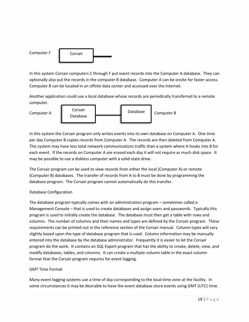
Computer F
In this system Corsair computers C through F put event records into the Computer A database. They can
optionally also put the records in the computer B database. Computer A can be onsite for faster access.
Computer B can be located in an offsite data center and accessed over the Internet.
Another application could use a local database whose records are periodically transferred to a remote
computer.
Computer A Computer B
In this system the Corsair program only writes events into its own database on Computer A. One time
per day Computer B copies records from Computer A. The records are then deleted from Computer A.
This system may have less total network communications traffic than a system where A hooks into B for
each event. If the records on Computer A are erased each day it will not require as much disk space. It
may be possible to use a diskless computer with a solid-state drive.
The Corsair program can be used to view records from either the local (Computer A) or remote
(Computer B) databases. The transfer of records from A to B must be done by programming the
database program. The Corsair program cannot automatically do this transfer.
Database Configuration
The database program typically comes with an administration program – sometimes called a
Management Console – that is used to create databases and assign users and passwords. Typically this
program is used to initially create the database. The database must then get a table with rows and
columns. The number of columns and their names and types are defined by the Corsair program. These
requirements can be printed out in the reference section of the Corsair manual. Column types will vary
slightly based upon the type of database program that is used. Column information may be manually
entered into the database by the database administrator. Frequently it is easier to let the Corsair
program do the work. It contains an SQL Expert program that has the ability to create, delete, view, and
modify databases, tables, and columns. It can create a multiple-column table in the exact column
format that the Corsair program requires for event logging.
GMT Time Format
Many event logging systems use a time of day corresponding to the local time zone at the facility. In
some circumstances it may be desirable to have the event database store events using GMT (UTC) time.
Corsair
Database Database
Corsair

20 | P a g e
This time standard does not recognize daylight savings time. The Corsair program has an option to use
GMT for its event logging. Database records are written with GMT time. When the Corsair program
displays a record, it translates from GMT to the proper local time at the Corsair computer. It properly
allows for Daylight Savings Time when it does this. The operator only sees time using his local time
zone.
Computer Clock Synchronization
Each Corsair computer can be configured to synchronize it’s time-of-day clock with the clock on the SQL
database computer. This can be done manually from the operator clicking on a button on the screen or
automatically at regular intervals. The SQL computer sends the clock value to the Corsair computer in
GMT format. The Corsair computer is set to the proper time for its local time zone.
Alarm and Call Events
Each alarm and call that is a part of the Corsair application database can generate as many as six
different events. For a standard alarm the events are:
AlarmTrip
AlarmAck (Alarm Acknowledge)
AlarmReset
AlarmTripCmd (Alarm Trip Command)
AlarmAckCmd (Alarm Acknowledge Command)
AlarmResetCmd (Alarm Reset Command)
The first three events are usually generated by a Corsair computer that is reading the 4-bit alarm status
out of a PLC. When it sees a new trip on an alarm it generates the Alarm Trip event. When it sees that
the alarm has been acknowledged it generates the Alarm Acknowledge event. When the alarm is reset
it generates the Alarm Reset event. There may be several Corsair computers on a network that are all
looking at the same PLC alarms. Only one should be configured to generate Alarm Trip, Ack, and Reset
events so that multiple records do not appear in the database for the same alarm. These events report
on changes in alarm status as read from the PLC. They do not report if a computer has caused the
change in status.
The CMD ‘Command’ versions of the event types are generated when a Corsair computer is used to
change the status of an alarm. If the operator acknowledges an alarm his computer generates an
AlarmAckCmd event at the same time that it commands the PLC to acknowledge the alarm. The
AlarmAck event will be generated as soon as the PLC shows the new acknowledged status.
Typically, only one Corsair computer of a multiple-computer system is configured to generate AlarmTrip,
Ack, and Reset events. All computers are configured to generate AlarmTripCmd, AlarmAckCmd, and

21 | P a g e
AlarmResetCmd events. These six event types are used with alarms of the ‘Standard’ category. Alarms
of other categories can generate different event type labels for these events. They might not generate
all 6 types of events. For example, and alarm of the ‘Notice’ category only has one type of event. When
the computer sees that the alarm is tripped in the PLC it sends a ‘Notice’ event instead of an ‘AlarmTrip’
event. It will not send any of the other 5 events.
A ‘Custom’ category is available that allows the developer to enter any event type label that he desires
for each of the six types of alarm and call events. If he leaves a label blank the event is not generated.
Test Events
A ‘Test’ event type is used to verify the connection between the Corsair software and the database
software. Test event may be generated by the operators clicking on a button on the event monitoring
window. They may also be generated from a Corsair script command. This can be done at a regular
time interval to verify that the connection is still working.
Corrections
Architectures Hardware architectures are methods of wiring together industrial control equipment in more complex
systems. Software architectures are methods of communicating data between machines and operators.
Corsair allows a lot of flexibility in implementing different architectures.
MBHR The MBHR ‘Modbus Host-Remote’ system is a standard feature with multiple-computer versions of the
Corsair program. It is used when a large number of computers need to access PLC data at the same time.
In small systems each Corsair computer can directly access PLCs over an Ethernet network.
PLC PLC
Corsair Corsair

22 | P a g e
Problems occur as additional Corsair computers are added to the network. Each PLC supports a fixed
maximum number of simultaneous network connections. 5 computers would require 5 connections on
each PLC. Peer-to-peer communications between PLCs will use additional connections. When the
number of Corsair computers exceeds the available connection count the system will not function
properly. Large numbers of computers will also tie up PLC processor time servicing communications
requests.
Many companies have separate networks for PLC control and for office (‘MIS’) use. The
networks should not be cross connected for security reasons and to avoid performance (and political)
problems. Running two network cables to each computer is not practical. The answer is the MBHR
system.
Two Corsair computers are hooked to both networks. They communicate with the PLCs using any of the
available Corsair communications drivers. They can both act as fully functional operator interface nodes
with the ability to read and write PLC data. They can support the specialized Corsair monitoring
PLC PLC PLC PLC PLC
Primary
Corsair MB
Host
Back up
Corsair MB
Host
Corsair MB
Remote
Corsair MB
Remote
Corsair MB
Remote
Corsair MB
Remote

23 | P a g e
functions for the PLC time of day clock, the battery status, and register values. These computers are
configured to act as MB Hosts.
Each of the office computers runs a copy of the Corsair software that has been configured to act as an
MB Remote. They interact with the Corsair Hosts instead of with the PLCs. Each Host can handle up to
100 Remote connections simultaneously.
The MB Remote computers can read data from the PLCs through the host computers. They can view
historical logs of data. They can turn-back the time on graphic screens. They cannot change PLC data and
they do not have the specialized Corsair monitoring functions.
All of the computers in the system – both Host and Remote – use the same Corsair application file.
Each Remote computer is assigned two host computers. The Remote will attempt to its primary host
first. If that attempt fails it will attempt to connect to its backup host.
Corsair Log data files can be kept on each of the Host computers. They need to run continuously.
Remote computers can access historical log information from the hosts without logging on their own
hard drives.
Plantwide Interface Plantwide Interface is a CorsairHMI development technique that is used in manufacturing or
correctional facilities where there are multiple control systems operated from several places. Each place
has a Corsair computer. Every area can see the interface data from every other area, but it can only
operate the things that it is responsible for. The A Building operator can see all the graphics from B
building but he cannot control it. He can only control the A building. The B building operator can see
the A building, but he cannot control it. The office can see both the A and B buildings but cannot control
either.
The Corsair difference is that it can use the same model file on every Corsair computer in the plantwide
interface system. This file contains information as to what can be seen and operated on each computer.
Each computer contains a small computer properties file that tells it what identity it is supposed to
assume. In emergencies when a computer is down provision can be made to easily change the
operating capabilities of another computer so that production can continue.
Plantwide interface can actually be less expensive than conventional interface architectures where
separate interface databases are used for each computer. When a system is added to the model file it is
copied to each of the computers so that they have the new capabilities. This development work only
has to be done once instead of multiple times for each separate database. MBHR remotes use the
same model database file as the operating computers do.

24 | P a g e
Multiple Models The hard drive on a Corsair interface computer holds a file that the program uses. This ‘model’ file holds
tags, interface screens and sheets, alarm information, and other things that are specific to the
customer’s installation. It is possible for a single Corsair program to use up to 100 Model files at the
same time. The operator switches between them to see different views.
Enterprise Interface Enterprise interface uses a combination of multiple models and MBHR technology. Suppose that a
company has headquarters in St. Louis and plants in Chicago, Cleveland, and Toronto. Each plant uses
pantwide interface with monitoring in its local office. Those offices are linked through the internet with
the S. Louis headquarters. Each Corsair computer in the headquarters is using 4 model files – one for
each of the plants and one for company-wide summary data. The summary model uses a special driver
to read data from the other models. It then totalizes the information and flags out of range values. One
headquarters computer provides a secure web view over the internet using a VLAN. Any employee with
the VLAN credentials can view the interface information at home or on a portable device.
Web The Corsair program can serve out dynamic web pages to any computer or mobile device with a
browser. The operator can monitor the system. It can be configured so that he can make changes from
the browser. Browsers must be HTML-5 compatible. There is no ‘app’ that has to be downloaded.
Browsers do not need Flash or Silverlight.
Serial Terminal Years before the Web computer systems used serial terminals to display text information. This was
typically in 24 or 25 rows of 80 columns each. The letters on the screen could be underlined, shown in
inverse, and flash. Many terminals were built to a software standard called VT-100 or ANSI. Some
computers have software that can emulate ANSI –compatible serial terminals.
Corsair has the capability to display text data on ANSI serial terminals. This is a one-way flow of
information. Keystrokes from the terminal’s keyboard are ignored.
A possible use for this feature in a jail is to display inmate count information for meals in the kitchen.
The Corsair computer is in a secure area but inmates have access to the kitchen. The one-way serial
connection provides a way for the inmates to see the data without compromising the security of the
control system. The Ethernet control network does not extend into inmate areas.
The CorsairHMI software can be used in a special mode where it does emulation of an ANSI terminal if
that is needed for these applications.

25 | P a g e
Licensing Every CorsairHMI program comes with a license file. The license file is used by the program to
determine what it can and cannot do. It determines the development capabilities, the maximum
number of screens, and several other options. The CorsairHMI website has a Terms of Sale document
that lists and prices various standard combinations of license features. These combinations are named
with letters.
Corsair has two options for temporary licenses. The first is a license that expires at a certain date. It can
be used until that time and then it expires. The second option is a limited run time license. It has a
maximum amount of time that the interface can run before it shuts off. It can then be restarted for
another time period. There is no limit as to the total run time with this license.
A 4-hour limited run time license may be available at no cost from CorsairHMI for evaluation,
development, training, and testing purposes. License files are not copy protected. Corsair users are
trusted to stay within the limits of their licenses.
Strategic Fit The CorsairHMI program can be an important part of a system integration firm’s business plan when
used in ways that utilize its unique capabilities. Other programs can be used to do most of what it does
but at a greatly increased cost and complexity.
Corsair has some very specific requirements for how some elements of a PLC program are configured.
If there is an existing PLC and an HMI operating a system, it is almost certain that some changes will
have to be made to the PLC program to accommodate a retrofit to CorsairHMI.
There are no annual fees for a Corsair integrator to maintain its status. Training and phone support are
available through CorsairHMI.
Linux CorsairHMI was originally developed as a Windows program. A Linux version of it is also available.
Model files developed using one operating system can be copied to the other and used with few, if any,
changes. Most Corsair features will work with either system. Corsair Linux uses GTK graphics.
Linux is not recommended for most installations because it is not compatible with many of the
computers that are found in industry. There are situations where it may be a good choice.
The first reason for Linux is to save money in a high-volume application. Linux is generally free.
The second reason for Linux is for stability over several installations with a long-term deployment. A
Linux version can be tested now and the same operating system installed 10 years from now. Windows
versions tend to be much more volatile.

26 | P a g e
The third reason for Linux may be a customer requirement. Some data centers may require Linux.
The fourth reason for Linux may be an opinion that the operating system is more stable. Stability is a
subjective matter. CorsairHMI gives integrators a choice.
Corsair is also available in a Linux version that can run on inexpensive ARM processors.
Education Traditional electronics classes were frequently focused on understanding and repairing television sets. TV repair was a common occupation, but the curriculum selection went beyond that. Television sets contained examples of most of the types of electronic systems that were used at the time. They contained oscillators, rf and audio amplifiers, high and low voltage power supplies, and so on. Understanding television provided a student with a background that would prepare him to go into a wide variety of electronic work. Curriculums that teach industrial computing need a software equivalent to the television set. They need to teach something that is practical yet covers a broad spectrum of topics. Modern operator interface software can fill this need. It provides a method for the student to learn about the following topics: 1. Computer graphics 2. Data communications using different protocols over Ethernet and serial links 3. Real-time data logging and viewing of historical information 4. Math functions including scaling, interpolation and statistics 5. Computer programming concepts including arrays, logic, program flow, data type conversion, and so on 6. Data exchange between programs using the clipboard, CSV files, and other methods Operator interface software fills a similar role to the television set in that it gives the student an introduction to a wide variety of topics in industrial computing. He can then go on in any of them as his needs and interests are further defined. CORSAIR SOFTWARE IN THE CLASSROOM Classroom software has some unique requirements that are not readily found in commercial products. Most of this is centered on the need for the student to learn the principles as much as possible and to spend as little time as possible learning the software. Software that is difficult to use wastes classroom resources and does not accomplish educational objectives. INSTALLATION ISSUES Corsair software is not copy protected. It does not make any changes to the Windows registry so there is no “install” and “remove” for the program. It is simply copied to a folder, and a shortcut is created to point to it. When the folder and shortcut are deleted the software is completely gone from the computer. The Corsair program itself is a single executable file. It includes all communications

27 | P a g e
drivers and function blocks. This is a sharp contrast to most programs that require hundreds of files and complete install and remove procedures. DEVELOPMENT AND RUN-TIME ENVIRONMENTS Corsair has its database development and run-time built into the same program. The student does not have to move from one program to another. Simple keystrokes are used to transfer instantly between development and run-time. Development error checking goes on continuously in the background during interface operation. Corsair includes historical data logging and viewing as a part of the program, not as a separate program. MODBUS PROTOCOL Corsair contains several drivers that use the industry-standard Modbus protocol. The Corsair communications trace function lets the student view the contents of data packets coming to and from the Corsair computer. This is a tremendous aid to understanding this popular protocol. TCP/IP EXPERT Corsair’s TCP expert functions enable a student to examine the network that his computer is hooked to. He can ping, resolve names to IP addresses and addresses to names, scan the network, and do other things. All this is done within the Corsair program using the Corsair database. MBHR PLC SIMULATION A computer running Corsair can act as a simulated PLC. Several other Corsair computers can read and write data from it. This prevents the instructor from having to have separate PLC hardware and programming software.
Future Directions
Distributed Hosting
The CorsairHMI program includes a Modbus Host-Remote (MBHR) system that is useful when
implementing large systems. It can use standard Modbus TCP protocol to communicate between
Corsair computers over an Ethernet network. It can also use a nonstandard extended version of the
protocol to achieve much higher performance than what is possible with tag-based communications.
MBHR is a valuable tool for Plantwide Interface systems where every computer can see what is
happening everywhere. Each computer can only control what it is allowed to control. Each computer
contains an identical copy of the Corsair application database.
Here is a simple system with no MBHR.

28 | P a g e
Each HMI talks to each of the 3 PLCs. Each PLC has to support 3 communications connections through
the Ethernet network. The Corsair Authority and Operator Log-in systems determine what each
computer can control.
HMI A
PLC A
HMI B
PLC B
HMI C
PLC C

29 | P a g e
The network can be expanded with MBHR single-point hosting.
In this case 4 office computers need to see the interface data. They could be on the same network as
the PLCs but it is usually desirable that they are on a separate network. If they all talked directly to the
PLCs each PLC would have to support 7 communications connections. As the number of office
computers increased the PLCs would be slowed down. Most PLCs have a fixed maximum number of
connections that they can support at one time. If this limit is exceeded communications failures will
occur.
HMI A
PLC A
HMI B
PLC B
HMI C
PLC C
HOST
OFFICE 1
OFFICE 2
OFFICE 3
OFFICE 4

30 | P a g e
This system uses an extra computer that has been added to act as a single-point MBHR host. It reads
data from the PLCs and the office computers read data from it. The PLCs have to service 4
communications connections instead of 7. All 8 Corsair computers in the system use the same
application database file. There could be as many as 100 computers in the office with no increase in PLC
communications.
In this system each plant computer operates as a normal interface. The host computer operates as a
normal interface with MBHR Host operation also running. Each office computer operates as an MBHR
Remote.
Single-point hosting like this works very well when there are a large number of office computers on a
separate network. The host computer is the only computer that is on both networks. If the host
computer fails the office computers cannot see the interface data but the plant computers will still run.
Systems with a large number of computers in the plant can overtax PLCs with communications from
them even before office computers are added. It would be possible to have a single Host computer
serve out data to every computer in the plant. This would make it so there is only one communications
connection to each PLC. The problem here is reliability. If the host computer fails every computer in the
plant fails. There may be speed problems with all communications running through a single host.
Many times the ideal is for HMI A to talk to PLC A directly, for B to talk to B directly, and so on. Each
area can continue to run when communications fail from other areas. Plantwide Interface requires that
HMI A sees the data from PLC B but this path may not be critical for operations. This can be
accomplished with MBHR distributed hosting. HMI A would host MBHR communications so that HMI B,
HMI C, and the office Host computer can see PLC A. HMI B would host MBHR communications so that
HMI A, HMI C, and the office Host computer can see PLC B. Now each PLC only has to support 1
communications connection and operating reliability requirements are met.

31 | P a g e
This system uses single-point hosting for the office computers and distributed hosting out in the plant.
Streaming Serial An engineer working at a nuclear power plant may desire to see interface data at home. There is a
concern over security when the plant control system is hooked to the Internet. Most security systems
are software based. They use two-way Ethernet data communication. This is true even of ‘one-way’
secure routers.
HMI A
A Host
PLC A
HMI B
B Host
PLC B
HMI C
C Host PLC C
Office
Host
OFFICE 1
OFFICE 2
OFFICE 3
OFFICE 4
32 | P a g e
Streaming serial is different. It uses two Corsair computers hooked together with RS-232 serial
communication. The key is that the communication is only connected in one direction. The plant-side
computer sends data to the Internet-side computer. There is no physical connection in the other
direction. There may be a fiber-optic link inserted between the two computers to guarantee electrical
isolation.
Someone may ‘hack’ into the browser view on the Internet-side computer but there is absolutely no way
that they can disrupt the operation of the plant through the streaming serial link. Because this is
hardware-based security there is no software that needs to be updated as new security problems are
discovered.
Comparison of Corsair Viewing Options The Corsair program offers several options for how interface and history data can be viewed. This
document is to summarize what features are available with these options. There are variations
depending on where data is stored so system architecture must be reviewed before features are
guaranteed.
A list of available options:
Option: Direct Local view of the Corsair Computer
This situation is when the operator is located at the Corsair computer. He can do anything that the
Corsair program is capable of.
Advantages: Security if the computer is locked in a secure area. Corsair password login is also available.
Disadvantages: No remote view. You have to be there.
Option: Remote operation of the Corsair Computer
This situation is when the operator is located at the Corsair computer. He can do anything that the
Corsair program is capable of.
Advantages: Security if the computer is locked in a secure area.
Disadvantages: Does not work well at the same time that someone is using the computer directly. The
two operators may want to look at different screens and do different things. There is a danger of the
remote operator accidently shutting down the Corsair software when he shuts down the remote
operation.

33 | P a g e
Option: Using the Corsair Computer as a Web host
The Corsair computer sends HTML pages to a web browser. This can be over a local area network or
over the Internet.
Advantages: Remote views anywhere with no special software or ‘app’ needed. No interference with
the local operator.
Disadvantages: Some limits in capabilities. The browser must be HTML-5 compatible.
Option: Using the Corsair Computer to host MBHR Remotes
The Corsair computer feeds data to remote computers that are running the Corsair software. This can
be over a local area network or over the Internet.
Advantages: Remote views anywhere the software is installed with almost as much capability as the
local computer. No interference with the local operator. Speed is generally excellent.
Disadvantages: Usually each remote computer has a copy of the Corsair application database.
Whenever it is updated on the Master (Host) the updates must be copied to each of the remotes.
Option: Using the Corsair Computer to drive ANSI Text Terminals
The Corsair computer sends text (not graphic) data to one or more text terminals through a serial line.
Advantages: Extremely secure as the serial line from the terminal to the Corsair computer can be left
unhooked. Secure enough for inmate areas at a corrections facility.
Disadvantages: Data is limited to up to 25 lines of 80 characters each. Update speeds are relatively
slow.
Option: Sending data to other software
The Corsair computer sends data to another program or programs in the form of .csv text files, SQL
database records, binary files, or other forms. This may involve FTP or HTTP-based data transfer.
Advantages: No interference with the local operator. Takes advantage of capabilities in the other
software that Corsair does not have.
Disadvantages: Requires special integration work with the other software. This may be extensive and
experiments may have to be done to see what works before contracting for a project.
Comparing the options:
Remote Software Requirements
Direct View: No remote software.

34 | P a g e
Remote Operation: Remote control software must be bought and installed on both the Corsair
computer and on the remote computer.
Corsair Web Host: No special remote software. The remote must use an HTML-5 compatible Web
browser.
MBHR Remotes: Each remote computer must have Corsair MBHR remote software installed on it along
with a copy of the Corsair application file.
ANSI Text Terminals: Terminals can be computers running terminal emulation software. It is
recommended that the Corsair program be used in a terminal emulation mode for this function as it has
some specialized advantages over programs like Hyperterm.
Sending data to other software: The other software must be purchased and configured.
Remote View Counts
Direct View: Zero.
Remote Operation: There can be many remote locations but only one can be used at a time.
Corsair Web Host: Limits may be set by the Corsair computers operating system. No more than 400 at
one time.
MBHR Remotes: A maximum of 100 remote nodes can hook into one host at a time. Many more
remotes are possible with MBHR cascading.
ANSI Text Terminals: Several terminals can be multidropped on a serial communication link. They will
all see the same thing.
Sending data to other software: Counts are dependent on the other software.
Operator Control Capability
Direct View: Yes.
Remote Operation: Yes.
Corsair Web Host: Some control capability if it is enabled.
MBHR Remotes: Some control capability if it is enabled.
ANSI Text Terminals: No control. View only.
Sending data to other software: Generally no control capability but there are some possibilities.
Corsair Application Development Capability

35 | P a g e
Direct View: Yes.
Remote Operation: Yes.
Corsair Web Host: Very limited but expanding.
MBHR Remotes: None and none planned.
ANSI Text Terminals: None.
Sending data to other software: None.
Trending Capability
Direct View: Yes. Shows the value at the cursor position.
Remote Operation: Yes.
Corsair Web Host: Limited trend viewing.
MBHR Remotes: Trends start to fill when the remote is started.
ANSI Text Terminals: None.
Sending data to other software: The software may have the ability to create trends.
Security
Direct View: Can be passworded. Lock the door to the control room.
Remote Operation: Determined by the remote software.
Corsair Web Host: Can be passworded but the password currently is not HTTPS. VPN security is
recommended if this is not adequate.
MBHR Remotes: No password security unless it is implemented as part of a VPN scheme. Adjustable
levels of IP or computer name matching.
ANSI Text Terminals: Perfect security. There is no connection that can do anything.
Sending data to other software: Depends on the other software.
CSV Review Capability
Direct View: Yes. Both graphing and Turn-Back Time (graphic screen history).
Remote Operation: Yes. Like the direct view
Corsair Web Host: Not yet.

36 | P a g e
MBHR Remotes: Depends on configuration.
ANSI Text Terminals: None.
Sending data to other software: The software may have the ability to review data.
SQL Event Record Review and Report Generation
Direct View: Yes. Large reports may slow down the CPU to an unacceptable amount for other tasks.
Remote Operation: Yes. Like the direct view
Corsair Web Host: Not currently planned.
MBHR Remotes: Depends on configuration. If a remote can get to the data it is a preferred way to
generate large reports.
ANSI Text Terminals: None.
Sending data to other software: The software may have the ability to review SQL data.
Diagnostics
This includes communications trace, PLC battery low monitoring, PLC clock set, PLC register monitoring,
and most of the Corsair ‘experts’.
Direct View: Everything that Corsair offers.
Remote Operation: Everything that Corsair offers.
Corsair Web Host: Very limited but features are being added.
MBHR Remotes: Generally none.
ANSI Text Terminals: None.
Sending data to other software: Generally does not apply.
System Status Windows
This includes windows that show the status of the various Corsair functions. It includes the about
window, memory summaries, and so on.
Direct View: Everything that Corsair offers.
Remote Operation: Everything that Corsair offers.
Corsair Web Host: Good support already with features being added. Should eventually be almost
complete.

37 | P a g e
MBHR Remotes: Generally none.
ANSI Text Terminals: None.
Sending data to other software: Generally does not apply.
Printing Capability
Direct View: Extensive. Many printouts have selectable color or black and white and portrait or
landscape.
Remote Operation: Depends on the remote control software.
Corsair Web Host: Defined by the web browser. Usually limited to screen dumps.
MBHR Remotes: Many of the same printouts as available from the direct view.
ANSI Text Terminals: No printing.
Sending data to other software: Determined by the other software.
Viewing Listed Drawings
Direct View: Yes. With printing.
Remote Operation: Yes, with printing depending on the remote control software.
Corsair Web Host: Soon.
MBHR Remotes: Yes. With printing.
ANSI Text Terminals: No.
Sending data to other software: No.
Remote Update Speed
Direct View: Fastest.
Remote Operation: Depends on the remote control software.
Corsair Web Host: Moderate speed, largely dependent on the Internet connection.
MBHR Remotes: Fast. With smaller systems screen update speeds can be close to those at the local
direct view.
ANSI Text Terminals: Slow.
Sending data to other software: Determined by the other software.

38 | P a g e
Future Direction
Streaming Serial will become available.
Architectures must be reviewed if the system involves IP video cameras or intercoms.
It is anticipated that the Web interface will be greatly enhanced with more and more capabilities that
are now only available on the local view. As this happens more projects will use Web clients where they
need MBHR remotes now. MBHR will never go away as some of its capabilities will never be available
on the web.

39 | P a g e
Operating the Corsair Interface CorsairHMI software is a powerful interface program that can be used in many different types of
industries. Each Corsair program must be developed to meet the needs of a user. Because of that
everyone’s Corsair program looks and operates differently. This manual is to show features of the
program that are general to most situations
Screens Some keystrokes are available to anyone viewing a graphic screen or a Corsair computer.
The ‘A’ then opens the alarm summary window. This is the same as clicking on the center sections of the
status bar on the bottom of some screens.
The ‘M’ then opens a maintenance window that shows configuration data for a placement. When it is
pressed Corsair checks to see what item is closest to the cursor to decide what to show.
The space bar is used for alarm and call screen changes. When it is pressed Corsair looks for a graphic
placement that shows a tripped alarm. It first looks on the currently displayed screen. If it cannot find
one there it looks on other screens. The screen is changed if needed and the cursor looks to the alarm
placement.
Control-P is used to start printing on the screen.
Control-Q is used to display quick trends of tag data. The operata moves the cursor near a value and
then presses the key to see the trend.
Control-T is used to operate Corsair Turn_Back_Time (TBT) feature.
Sheets Sheets are Corsair windows that show data in positions called ‘cells’. Cells are arranged in rows that go
across the computer screen and columns that go up and down. One cell is shown in a different color
than the others. This is the ‘current cell’. The current cell may be changed with the arrow keys or by
clicking on another cell. The sheet can scroll horizontally or vertically to see cells that are beyond the
edge of the window.

40 | P a g e
Some cells of a sheet are editable. If the current cell is editable the ‘F2’ key will open the window that
edits the value. The same thing can be accomplished by a second click on the current cell.
The operator can select a range of cells on a sheet. He moves to the upper left cell of the desired range
and presses the ‘.’ key. Then he arrows down and right to get the rest of the range.
Range selection is one option for printing. Control + P opens the sheet printing window.

41 | P a g e
The first option is to print the entire sheet. The second option is to print the range of selected cells.
The third option is to print all the rows of the sheet that have data. When the computer gets to a blank
row when all the other rows below it are blank it stops printing.
A similar sheet operation works with the ‘File’ ‘To Clipboard’ menu option.
This operation puts the data into the Windows clipboard in a way that is compatible with commercial
spreadsheet programs.
A similar operation is available to export sheet data to a CSV delimited test file that can be used by other
programs.
Operating a Setpoints Sheet Most PLC projects have variable setpoint data stored in the PLC. These may be high temperature alarm
thresholds in degrees or process water target flows in gallons per minute. A large system may have
hundreds of setpoint values. Conventional interfaces may have these setpoints scattered around on
various operator screens near the equipment that they are working with. CorsairHMI can do this but it
offers an additional option. All the setpoints can be collected together at one place on a sheet. This
sheet can be printed for a record of what the setpoints are at some point in time. If the values are
accidently changed the operator can go to one place in the Corsair program to type in all of them.
The PLC programmer usually is responsible to make sure that the operator does not enter setpoint
values that are out of allowable ranges. A high temperature alarm should not be set so high that it is
disabled. The PLC programmer may write logic that bounds setpoints to values that he is comfortable
with. That way the operator cannot compromise the system. A Setpoints sheet typically has a Value, a
Minimum and a Maximum column. The PLC programmer locks values into the Minimums and
Maximums. The operator enters the Value column. An entry that is out of the limits is corrected by the
PLC logic. The operator can see the allowable range.

42 | P a g e
The left-side ‘Register’ field is a PLC address. It is there to assist the programmer.
A Reasons Sheet It is common for a piece of equipment to have several interlocking conditions that must be made before
it can start. There may be downstream equipment or safety considerations or temperature alarms. It
may not be obvious to an operator what the ‘reason’ is that a motor will not start. The person that did
the PLC programming can look at the programming software on a computer screen and find the reason.
This takes time. Frequently the reason is something as simple as a disconnect that was left off or a
tripped pull cord safety.
One option with Corsair is to develop a ‘Reasons’ sheet for each motor. It shows a list of reasons on the
left side of the sheet. The right side of each row of the sheet says ‘Ready’ or is blank. If it is not ready
that reason needs to be investigated.
Frequently the way that things are wired means that one condition can change more than one reason. If
the power is shut off on a conveyor safety devices on that conveyor may not be ready. Proper design
practice is to have the most significant reasons closer to the top of the sheet. The most efficient method
is for the operator to investigate the reasons in top to bottom order.
The goal of reasons sheets is to enable the operator to rectify some situations without calling
maintenance and to have some information available if he has to call maintenance. The extra time that
is needed to implement reasons sheets is more than saved over the lifetime of a control system.
Alarms
Stuff about alarming
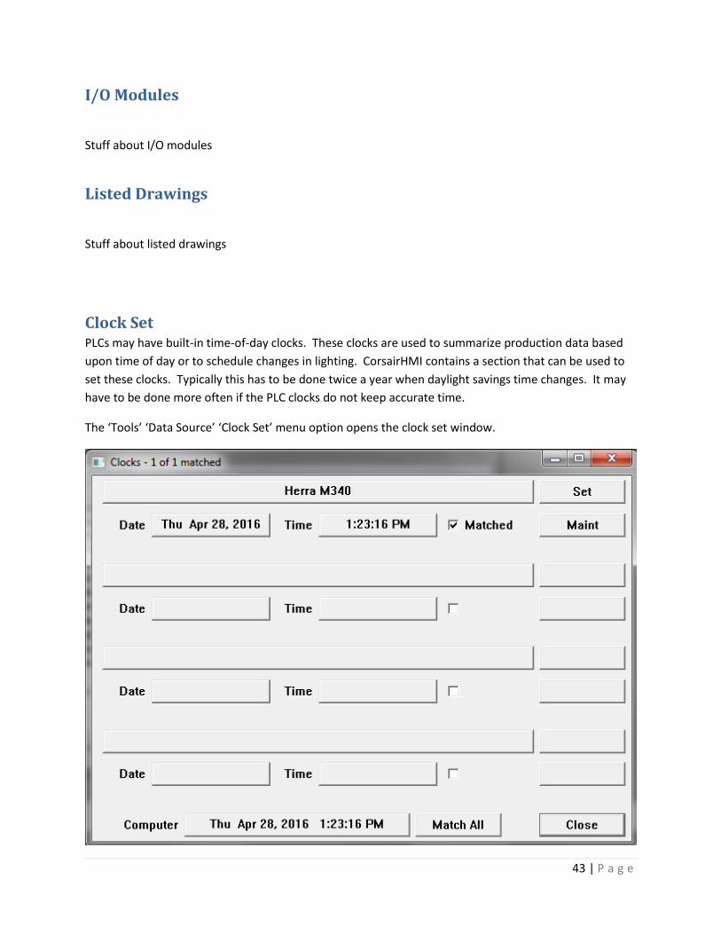
43 | P a g e
I/O Modules
Stuff about I/O modules
Listed Drawings
Stuff about listed drawings
Clock Set PLCs may have built-in time-of-day clocks. These clocks are used to summarize production data based
upon time of day or to schedule changes in lighting. CorsairHMI contains a section that can be used to
set these clocks. Typically this has to be done twice a year when daylight savings time changes. It may
have to be done more often if the PLC clocks do not keep accurate time.
The ‘Tools’ ‘Data Source’ ‘Clock Set’ menu option opens the clock set window.

44 | P a g e
This window shows all the PLCs that have clocks that are recognized by Corsair. The operator can arrow
up and down through the list. The title bar shows how many clocks there are and how many are
‘matched’. A matched clock has a time value within 5 seconds of the clock on the Corsair interface
computer.
Most computer clocks will automatically adjust when daylight savings begins and ends. The current
value of the computer clock is shown on the lower left side of the window. There is a ‘Match All’ button
on the bottom of the window. When it is activated Corsair sets the clocks on all the PLCs to match the
computer clock. Typically this is all that needs to be done twice a year.
The ‘Set’ button next to each clock opens the individual PLC clock set window.
The Source column shows the current clock values coming from the PLC. The Computer column shows
the values coming from the Corsair computer. This enables the operator to set individual clock items or
to match just that PLC without matching the others. He enters a number into the ‘Set’ column and then
clicks on the corresponding ‘Set’ button.
Battery Low

45 | P a g e
Quick Trends Quick trends are one way for the operator to view a plot of a data value versus time. An operator can
view a quick trend plot of any number on a graphic screen by placing the cursor next to it and pressing
Control-Q on the keyboard.
The quick trend plot starts out empty. Corsair starts building up the data and the plot works its way
across the window as soon as it is opened. The data is lost when the window is closed. The scale that is
used for the plot is determined automatically from the data.
The first two sections of the status bar show the minimum and maximum values since the window was
opened. The third section of the bar shows the value of the tag at the time of the cursor position. The
fourth section of the bar shows the time of the cursor position.
The ‘View’ menu item presents selection options for the time width of the quick trend window. The
‘View’ ‘Details’ menu item displays some information about the plotted data.
Trends Trends are plots of the data values of one or more tags over time. Trend data starts to build up when
the Corsair program starts running. It is lost when the program quits running or the computer loses
power.

46 | P a g e
A trend can have plotted traces from multiple tags. All of the traces use the same minimum and
maximum scaling.
The name of one tag is shown on the left side of the bottom status bar. If the mouse cursor is moved
over that plot trace the value at that time appears on the right side of the status bar. The page up and
down keys can change which tag is shown at the bottom.
The time corresponding to the cursor position appears in the center of the window under the plot
region.
Control-P can be used to start a print of the trend.
Log Plotted Data Data that is stored in a log file can be plotted versus time on the computer screen. The first step may be
to click on the ‘Data Logs’ button on the Corsair desktop window.

47 | P a g e
A window is opened for the plot display. Log data is saved in a disk file so it is not lost when the
computer power is off.
The tags whose values are saved in the data log are listed on the bottom of the window. Each tag has a
maximum and minimum scale value. The tag with highlighted data is the ‘current tag’. Its scale is the
one shown on the left side of the graph area. The current tag can be changed by arrowing up or down.
Plotted log data is different than a trend plot because each tag is plotted to its own scale.
The first step is for the operator to specify a time interval. There is a selector on the top of the window
that can select a time interval. It can range from ‘Last Hour’ to ‘Last Month’. The two radio buttons to
the left of this selector are used to pick if it is used or if custom ‘From’ and ‘To’ times are entered.
Once the desired time interval is set up the operator can click on the ‘Refresh’ button to see any
available plot data for the time interval.

48 | P a g e
The system defaults to two X time cursor lines, one red and one blue. They can be moved by putting the
mouse cursor arrow over the cursor line, pressing the left mouse button down, and moving the cursor.
Releasing the button drops the cursor line at the new position. At the top of the graph the time
corresponding to each cursor line position is shown. The red cursor’s time is shown in red text. In the
center of the window the time difference between the two cursors is shown.
The values of the current tag at each cursor line time are also shown. The difference between the
values at the cursor lines is shown in the center.
If the operator sees a disturbance at some section of a trace he can place the X cursor lines on either
side of it and pick the ‘Times’ ‘Set to X Cursors’ menu option. It changes the plots ‘From’ and ‘To’ times
to magnify the disturbance.
If a tag has been set up to integrate over time Corsair can integrate the value between the two cursor
times. This data is in the table on the bottom of the window. If the tag is a flow in gallons per minute
the integrated total is in gallons.
Y value cursor lines can be enabled. They can be adjusted up and down to see two values and their
difference.
Corsair has options for the operator that does not want to see all of the plotted lines on the log. One
option is to click on the visibility X marks on the bottom tag list. Another option is pressing ‘S’ to go to
single trace mode. With single mode only the current tag’s trace is shown. Arrowing up and down will
change between traces.
History The History View window is very similar to the log plotted data window except that it is not associated
with a particular data log. It is opened from clicking on the ‘History’ button on the Corsair desktop.
The log plotted data window opens with a list of the tags that are on that log. The history window
opens with no tags.

49 | P a g e
The operator has to select what tags he wants to see on the history window. He does this by clicking on
the ‘Tags’ button on the upper left side and selecting the Tag that he wants. He may select up to 400
tags for the window. When the refresh button is clicked the computer tries to fill in the history data any
way that it can find it – from data logs or trend samples. Operation of the window is like the plotted
data window with the same control options.
Turn-Back-Time The Turn-Back-Time feature is an alternative to plotted views of historical data. Plotted data requires
the operator to be familiar with tag names of the data items. Many times the operator may not be
interested in how a value changes over time. He may just need to know its value at a single point in
time, like last night at midnight. Turn-Back-Time is an easy to use solution to these problems. The
computer uses the information that is available to it to construct as completely as possible what a
graphic screen looked like at a point in time.
Turn-Back-Time is accessed from any screen by pressing the ‘Control’ and ‘T’ keys. A window appears
that has a time and date picker control on the upper left corner.

50 | P a g e
The operator enters the desired date and time into this control. When the time is correct he clicks on
the ‘Refresh’ button and the computer shows him the turned-back version of the screen. It looks
through trend samples and data log files to find out as much as it can.
[ the auto-refresh mode is not operational at this time ]
A window can be turned back to a time like yesterday at noon. Clicking on ‘Start’ activates the auto-
refresh mode. Every 5 seconds the computer advances the time window by 5 seconds and then updates
the screen. It ‘plays back’ what happened at that point in time. This playback rate can be sped up by a
factor of 2 or 10 times. The playback can also go in reverse.
Event Logging
Xxx
Report Forms Report forms are used to generate printed and disk reports from data that has been logged using the
Event Logging system.

51 | P a g e
Web View
Xxx
Multiple Models
Xxx
Touchscreen Cleaning Touchscreens get dirty in industrial applications. They need to be cleaned in accordance with the
manufacturer’s recommendations. Cleaning an operating interface screen can be a problem if it results
in accidental activation of touchscreen targets. Corsair includes a standard feature that enables
touchscreen cleaning without any potential problems. It is a special window that does not respond to
touches or mouse clicks. It also ignores all keys except for the Esc key. This allows it to also be used for
cleaning the keyboard.
One way to get to the cleaning screen is to use the Help/About menu option. There is a button labeled
‘Clean’ that opens the cleaning window. It remains open for 60 seconds or until the Esc key is pressed.
Development Development is the process of creating a model file for the Corsair program to use. Most Corsair
licenses support development. The developer must enter model database information, draw graphic
screens, enter scripts, and do many other activities to create a model that is complete enough for use.
Installation Corsair is a portable application that does not need to be installed into the computer’s operating
system. It can be run directly from a USB drive or it can be copied to the computer’s hard drive. It is
uninstalled by deleting the files. It is not copy protected in any way. Users can copy it to another
computer for backup purposes. They are expected to honor the limitations of the license that they have
purchased.

52 | P a g e
Typically the first step for a Windows machine is to create a folder named ‘corsair’ on the root of the C:
drive. CorsairHMI will supply a minimum of two files. The first is the Corsair program. Its file name is
‘corsair.exe’. It should be copied to the ‘c:\corsair’ folder. The second file is the license file. Its name
has the form ‘CHMI*.cky’. The name of the license file begins with ‘CHMI’ followed by some additional
letters. It ends with a ‘.cky’ extension. It must be copied into the same folder as the corsair.exe file.
The license file tells the Corsair program what features have been purchased by the customer for his
system.
An integrator may have several license files from different customers on his computer. If multiple
licenses are in the same folder it is not predictable which one will be used by the program. Common
practice is to rename unused license files by inserting a capital ‘X’ at the beginning of the file name.
The next step is typically to create a desktop shortcut to run the program. Right-click on the corsair.exe
file and pick the ‘Send to Desktop (Create Shortcut) ‘ option.
The program needs a computer properties file. It is typically named ‘corsair.cfg’ and it is kept in the
same c:\corsair folder. If the system was not supplied with a computer properties file the developer
must make one.
The program also needs a developer preferences file. It is named ‘corsair.pre’ and it is kept in the same
folder. If the system was not supplied with a developer preferences file the developer must make one.
Each system needs at least one model file. The model file is typically named ‘corsair.cap’. It can be kept
in any folder but it usually is in the same folder as the other files.
Some developers may want to place a splash icon in the blank background of the Corsair desktop. This
file must be a Windows bitmap. Its name must be ‘corsair.bmp’.
The final list of files is typically:
Corsair.exe – the Corsair application
CHMI*.cky – the license
corsair.cfg – computer properties
corsair.pre – developer preferences
corsair.cap – the model
corsair.bmp – the optional splash icon
The suggested procedure for creating the rest of the files is for the developer to start the corsair
program from the desktop shortcut. He then picks ‘Users’, and ‘Change Levels’ from the main menu.

53 | P a g e
The developer then clicks on ‘Administrator’ and enters the default password which is ‘admin’. This
enables the OK button so he can change the user level to Administrator. After clicking on OK it should
say ‘Dev: Admin’ on the status bar on the lower right side of the Corsair desktop window.
The next step is to create the ‘corsair.pre’ developer preferences file if one was not provided with your
system. From the main menu select ‘Setup’ ‘Default Fields’ and answer the prompt. Then do ‘Setup’
‘Graphic Font’ and select something like Courier New, Bold, 12 point. Then do ‘Setup’ ’Preferences’ to
open the preferences window.
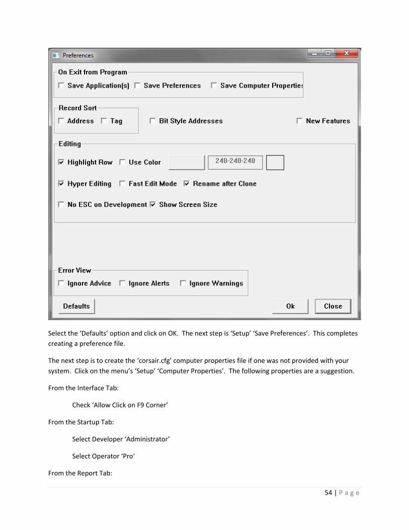
54 | P a g e
Select the ‘Defaults’ option and click on OK. The next step is ‘Setup’ ‘Save Preferences’. This completes
creating a preference file.
The next step is to create the ‘corsair.cfg’ computer properties file if one was not provided with your
system. Click on the menu’s ‘Setup’ ‘Computer Properties’. The following properties are a suggestion.
From the Interface Tab:
Check ‘Allow Click on F9 Corner’
From the Startup Tab:
Select Developer ‘Administrator’
Select Operator ‘Pro’
From the Report Tab:

55 | P a g e
Check ‘Operator Printing’
Check ‘Landscape’
For the Large font put Courier New, Bold, 14 point
For the Medium font put Courier New, Bold, 10 point
For the Small font put Courier New, Normal, 10 point
From the Security Tab:
Check ‘Allow Exit’
DO NOT check ‘Lock Access to Desktop’
Check ‘Allow Minimize’
Enter ‘corsair’ for a Base Session Name
Clicking on ‘OK’ enters the computer properties you have selected. The ‘Setup’ ‘Save Properties’ menu
option creates the file. Now when you start the program from the shortcut it initializes with
Administrator privileges.
The next step is to create an empty Model file if one was not provided with your system. Select ‘Setup’
‘Model List’ from the main menu. Press F2 to edit the first model specification. Fill it out like this and
click on ‘OK’.
The ‘Setup’ ‘Save Properties’ menu option must be used now to save the Model List part of the
computer properties. The model file has been specified. Now it must be created. From the
‘Setup’’Model List’ screen menu use first the ‘Empty’ and then the ‘Save’ option.

56 | P a g e
This completes creation of the files that are required for a CorsairHMI system. Now the development
work can begin.
Development Basics Most Corsair development activities can be performed by clicking on a menu item. There are some
keystrokes that may be used to do the same things. Some of these keystrokes have alternative keys that
do the same thing.
The ‘F1’ key is used for going to a record, selecting a record for a link, and opening entry assistants.
The ‘F2’ ‘Edit’ key is used to start editing a data item.
The ‘F3’ key is used in some places as an alternative edit key.
The ‘F4’ ‘Create’ key is used to create a data item. The alternative keystroke is the ‘Ins’ key.
The ‘F5’ ‘Clone’ key is used to create a duplicate of a data item.
The ‘F6’ key is used to change database entry modes between a development sheet and single-record
entry.
The Control+F6 key combination can be used to jump into a development mode for some windows.
The ‘F7’ ‘Zoom’ key is used to zoom on a record. The alternative keystroke is the ‘Z’ key.
The ‘Del’ key is used to delete a data item.
‘Ctrl’ plus ‘P’ can frequently be used to initiate printing.
Development capabilities can be set to different levels. Those levels are ‘None’, ‘View’, ‘Full’, and
‘Administrator’. ‘None’ means that development cannot be seen. ‘View’ means that it can be seen but
not changed. ‘Full’ means that most changes can be made. ‘Administrator’ means that anything can be
done. If the current level is greater than ‘None’ it is shown on the bottom right side of the Corsair
desktop status bar. The label ‘Dev: Admin’ means that the level is set to Administrator.
Development changes are made with the ‘File’ ‘Save File’ menu option.
Development level is changed with the ‘Users’ ‘Change Levels’ menu option.

57 | P a g e
This window opens up with the radio buttons set for the current operator and developer levels. Either
can be reduced by picking that option and clicking on ‘OK’. To increase a level a password has to be
entered. The default administrator password is ‘ADMIN’. If it hasn’t been changed typing it in, clicking
on the ‘Administrator’ radio button, and clicking on ‘OK’ will enable development. After development is
finished the ‘Users’ ‘Change Levels’ menu option is used to reopen the window. Clicking on ‘None’ and
OK will shut off development.
Many development activities involve selecting colors. Colors are specified by three numbers separated
by hyphens. Each number can range from 0 to 255. The three numbers correspond to levels of Red,
Green, and Blue. 0-0-0 is black. 255-255-255 is white. 0-255-0 is green. Any color can be specified by a
three-number combination.
Corsair uses a color selector window to aid the developer when entering color values. One version of
this window looks like this:

58 | P a g e
When the developer finds a color that he wants to reuse it can be added to the 16 custom colors that
the window allows. The next time that the color selector is opened that selection will be available.
Many development activities involve selecting a Font for the computer to use to show some text on the
screen or for a printout. The operating system has a font selection window. One version of this window
looks like this:
A font is specified by a name, by a point size, and by options for Bold, Italic, Strikeout, and Underline.
Development databases are initially viewed as sheet-style development.

59 | P a g e
Each row corresponds to a record. Each column corresponds to a field. The intersection of a row and a
column is a single position called a cell. The current cell is shown in a different color. It can be changed
with the arrow keys.
The developer uses the F4 Create key to insert a record. He uses the F5 key to clone a record. If he
wants to edit a cell he presses the F2 key. The F6 key is used to switch back and forth to single-record
editing mode.
Databases
Sessions
A Corsair model (.cap) file can include multiple data records that are known as session records. Some
systems may involve several physical computers located in different parts of a facility each running
copies of the Corsair software. They would be linked together on a network along with several data
sources. Typical data sources would be PLCs - Programmable Logic Controllers. Each computer would
have its own copy of the same Corsair application file. Session records are to create differences in how
the Corsair program acts on different computers that all use identical application files.

60 | P a g e
For example, let's assume that a project utilizes 5 computers in areas designated as 'Batching',
'Production', 'QC', 'Warehouse', and 'Office'. There would be 5 records having these labels in the
computer database. Each physical computer would have a unique Computer Properties file on it's hard
drive. That file includes a label that corresponds to one of the session records. This is known as the
'base' computer record for that location. This is a label for the Corsair program and it is not the same
name as the operating system's network ID for that computer.
The base computer record for a location can be used to determine which data sources will communicate
with that location. There may be a PLC on a molding machine. The data source record includes a list of
what computers have been selected to communicate to that data source. 'Batching', 'Production', and
'QC' may need to talk to the molding machine but not 'Warehouse' or 'Office'. The list associated with
the molding machine data source is what permits this to happen. The data source is considered to be
'Live' for the Production computer and 'Memory' or 'Not Real' for the warehouse computer. Designers
of large systems may need to review how many simultaneous network connections ('sockets') are
allowed by their data sources. This may limit how many computers can treat the data source as being
'Live'.
The 'Base' computer record is used to configure data acquisition. The 'View' computer record is used to
determine what the operator sees. For simple systems they are the same record.
Initially when the Corsair program is started the view computer record is the same as the base computer
record. Corsair offers an operator log-on system. This is not the same as the login that is used by the
computer's operating system. The administrator of the Corsair log-in system can create multiple users
each with a unique password. He may enter a computer name for each user. When a user logs in
Corsair looks to see if a computer record matches what was entered for that user. If one is found that
record becomes the new view computer record as long as that user is logged on.
Corsair can act as a web host using its dynamic HTML generation capabilities. Multiple clients can be
logged into a Corsair host at the same time with different view computer records. This is regulated by
the log-in type setting for the web host. One setting is 'Log in to operate, bypass to view'. The client can
choose to log in with a user name if he desires to be able to operate the interface. He can bypass
without a login if all he needs to do is view Corsair data.

61 | P a g e
If the client chooses the bypass option the Corsair program looks for a computer record that has the
'Bypass Web Client' type. That computer record becomes the view computer for that client. If there is
not a bypass client record the view computer defaults to the base computer record.
If the web client elects to login he must enter a user name and password. The view computer for that
client session is the computer name that was entered for the user name.
Each session record has an associated index number value. These are positive numbers that begin with
zero. These values are used with Corsair session-indexed addressing. Changing the view session would
then change what address the interface sees. For example, an integer tag on a PLC may begin with
Modbus address 40001. If the tag is session-indexed a view session with an index value of 0 would
display the value in register 400001. A view session with an index value of 1 would display the value in
register 400002.
Session-indexed tags are frequently used for authority tags. The authority system can be used to
determine which view computers can operate a tag and which ones can operate and see alarms. The
corsair computer can generate different alarm summaries for different users.
ID Field
Hook 1-4 fields
Screen (First Screen)
TCP ID
IP (PLC Network IP Address)
Host (MBHR Host?)
MIS IP
Remote (MBHR Remote?)
Host (MBHR Primary Host)

62 | P a g e
Host (MBHR Backup Host)
Write (Remote can write data?)
Extended Protocol? Y/N
TCP Port (MBHR TCP Port (0 defaults to 502)
Memory Tag MBHR ID 1
Note 1, 2, and 3
Other IP Address
Port Objects Zoom
Models Zoom (Model Specifications)
Icon
Location #
Sequence #
Logging – Do Logging Y/N
X size
Y size
There is a single-record editing window for session records.

63 | P a g e
xxxx
Drivers A driver is a portion of the CorsairHMI program that is most commonly used to communicate with a
device. A PLC driver is used to communicate with a Programmable Logic Controller. Each driver has
been written to work with a protocol. A protocol is a set of rules as to how communications between
the two devices is going to occur. Modbus is one example of a group of protocols. Corsair includes
several types of Modbus drivers to talk to different types of Modbus devices. The CorsairHMI Designer
manual includes a complete list of available driver types.
Every Corsair program contains all the available drivers. The first step to use a driver is for the
developer to create a record in the driver database. This record is given an identifying name and a type
that shows which driver it is hooked to. Multiple driver records can use the same or different drivers.
Each driver record should contain at least one data source. A PLC is an example of a data source. One
driver record of a Modbus driver may contain 20 data sources. Each of these data sources would be a
Modbus-compatible PLC.
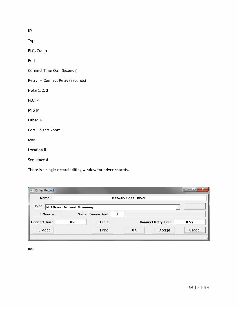
64 | P a g e
ID
Type
PLCs Zoom
Port
Connect Time Out (Seconds)
Retry - Connect Retry (Seconds)
Note 1, 2, 3
PLC IP
MIS IP
Other IP
Port Objects Zoom
Icon
Location #
Sequence #
There is a single-record editing window for driver records.
xxx

65 | P a g e
Data Sources A data source is a place that the Corsair program goes to get tag data. Data source driver records are
created under driver records. A data source under a Modbus driver may be a Modbus-compatible PLC.
A data source under a General Electric driver may be a General Electric PLC.
ID
Driver Parent
The driver field shows when driver the data source is located under. It shows two question marks for a
memory data source that is not under a driver. It is possible to move a data source from one driver to
another if the interface is not running. When the interface checkbox is not checked the driver selection
can be changed.
Register Block Zoom
Tags Zoom
Real Y/N
The ‘Real’ or ‘Live’ yes/no field is used to determine if Corsair will try to communicate with the data
source. It is set to ‘No’ for demonstration use of the software. For a source to be ‘live’ the following
must be true:
1. The field is set to ‘yes.’
2. Driver-specific parameters like IP address must be correctly entered.
3. The sessions zoom has it enabled for the session.
4. If a ‘live’ tag is used its value must be ‘on.’
IP Address
The IP address on a data source record is used in situations where the driver requires an IP address and
that address is to be entered on the data source record. Some drivers require IP entry on the driver
record instead of the source record. Drivers that use serial parts do not require only IP addresses.
The ‘MIS IP’ and ‘other IP’ fields are enterable values that can be shown on the communications
architecture printout. They are not used by drivers.
Node Number
Time-Out (seconds)
I/O Zoom
Authority Link
Sessions Zoom
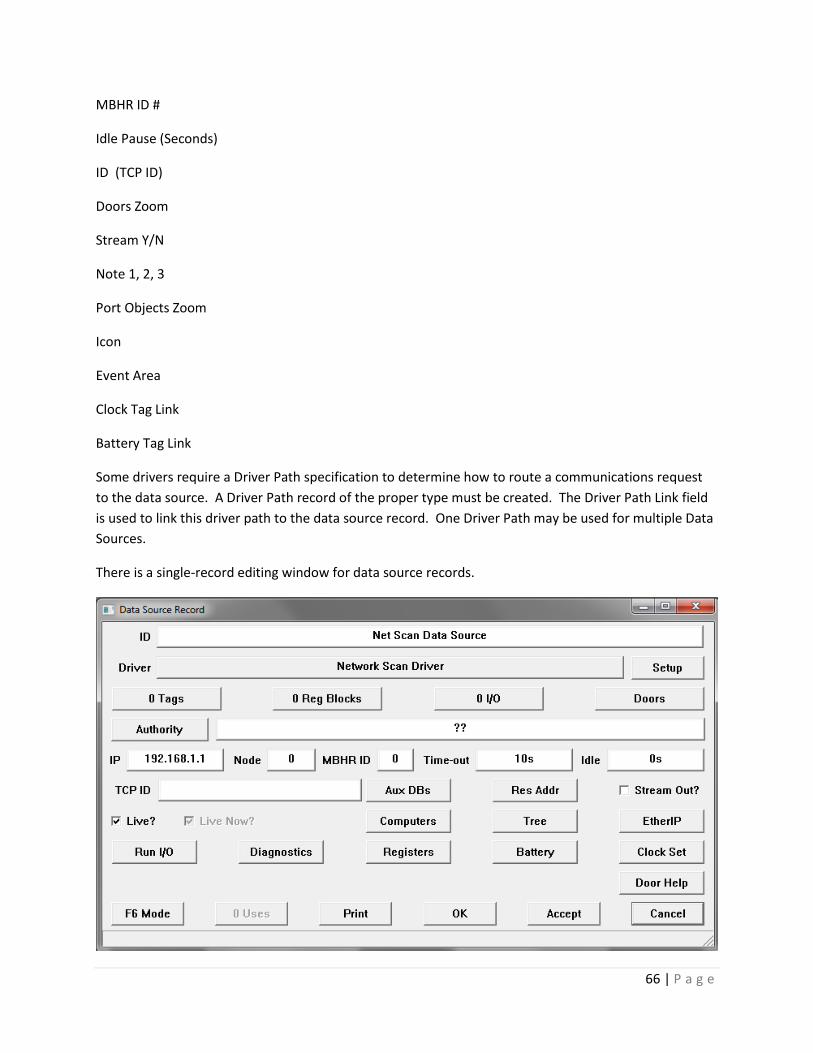
66 | P a g e
MBHR ID #
Idle Pause (Seconds)
ID (TCP ID)
Doors Zoom
Stream Y/N
Note 1, 2, 3
Port Objects Zoom
Icon
Event Area
Clock Tag Link
Battery Tag Link
Some drivers require a Driver Path specification to determine how to route a communications request
to the data source. A Driver Path record of the proper type must be created. The Driver Path Link field
is used to link this driver path to the data source record. One Driver Path may be used for multiple Data
Sources.
There is a single-record editing window for data source records.

67 | P a g e
The ‘Res Addr’ button is used with some drivers to automatically create tags on the data source. These
tags will use the special reserved addresses that are specific to that type of driver.
Register Blocks
Name
Data Source Parent
The developer must enter both the Start and End address of the block. The format used to enter these
addresses varies with the type of the driver that contains the source. The end address should be a
location that is after the start address. If the End address is left blank it is assumed that the block starts
and ends at a single address.
When the ‘Private’ flag on a block is set to Yes the developer is marking that the block is used by the PLC
and is not to be read or written by the Corsair interface. There should not be any tags or doors located
in a private register block. This feature is for documentation purposes.
The OIT or HMI changeable Yes/No field should be set to ‘Yes’ if Corsair has changeable tags or Door
data located within the block.
There is a single-record editing window for register block records.
Some drivers can show a length value for the block based upon the entered Start and End address.

68 | P a g e
Tags A tag is a storage location in computer memory that holds data while the Corsair program is running.
Tag Types
Corsair tag types describe the way that data is encoded. There are several types for many different
purposes. The exact way that each type is addressed depends on the type of driver that is used.
When a tag record is created it initially has the ?? undefined type. The developer can press ‘F2’ on the
type field and enter a type. He can also then press ‘F1’ to bring up a tag type selector listing all available
types.
The ‘indicator’ tag type is a single-bit logical flag. Indicators can be changed by the PLC and read by the
Corsair interface. They indicate on/off conditions. The corsair program cannot change the status of an
indicator. The default text description for the program cannot change the status of an indicator. The
default text description for the zero state of an indicator is ‘Off’. The description for the one state of an
indicator is ‘On’. Tag enumerations can be used to change these descriptions if desired.
The ‘switch’ tag type is also a single-bit logical flag. Switches can be changed by either the PLC or the
Corsair interface. When a human operator operates a switch tag he picks options from a switch
operating window.
The ‘button’ tag type is a single of data The Corsair program turns the bit on to signal to the PLC to do
something. The PLC then shuts the bit off. The Corsair operator does not have an option to shut off a
button.
The ‘HOA’ tag type is a specialized 3-bit data type. One of the bits is controlled by the PLC. The other
two are controlled from the PLC or from the Corsair interface. This type is commonly used in control
applications where it is desired to force a motor on or off independently of normal automatic logic.
The ‘integer’ tag type is for a 16-bit integer value. It may be changed by the PLC or by the Corsair
program. It may be signed value ranging from -32768 to +32767. It may be an unsigned value ranging
from 0 to 65535.
The ‘Double Int’ tag type is for a 32-bit integer value. It works over a much greater range than the 16-bit
integer type.
The ‘Float’ tag type is for a floating point value encoded in IEE standard 32-bit format.
The ‘4-bit alarm’ type is for alarm status data arranged in Corsair standard bit pattern. The ‘1-bit alarm’
type is for another type of alarm status data. The same bit patterns are available for calls.
String, Loose String, and Reverse String data types are for encoding of ACSII string data in PLC memory.
Each type uses a different scheme for arranging the characters in PLC memory. The choice usually
depends on the type of PLC and programming system that it uses.

69 | P a g e
The ‘Cascade’ type is used for larger-value integer data in PLCs that do not support 32-bit integers. It is
useful in cases where integer precision needs to be maintained in totalizing. The Cascade uses two 16-
bit registers. The net value is the second register multiplied by 10,000 and then added to the first. A
total of 999,999 is possible with a Cascade.
The bit-field types vary from 1 bit to 16. Data encoded in these types is always unsigned and cannot be
negative. Bit fields are frequently used to encode sequence options in recipe systems.
Tag Configuration
All tags are either ‘Memory’ or ‘Live’. A memory tag gets its value from what is stored in the Corsair
computer’s memory. This value can be changed by the operator, by a script, from a block, or written
from another computer. A ‘Live’ tag gets its value from a data source using a driver. The driver
performs a scanning function where the value from the data source is continuously read into tag
memory.
A company may have a tank that holds water. A pressure transmitter tied to the bottom of the tank is
wired to a PLC. The PLC translates the electrical signal from the transmitter into a tank elevation in feet.
This elevation is found at a memory address in the PLC. The developer sets up a driver and inserts a
data source for the PLC under it. Under the data source he inserts a tag named ‘Tank Level’. This tag is
linked to a value placement on a screen. Now the operator can see the number of feet of water that are
in the tank.
Every Corsair tag is an array. An array is a collection of values of the same type. Each of these values is
an element of the array. An integer array with a size of 4 could contain the values 12, 97, -258, and 473.
Elements of an array are distinguished by index number. Index numbers start at 0. They can be as large
as the size of the array minus one. This array would be:
Element Value
---------- - --------
Index 0 12
Index 1 97
Index 2 -258
Index 3 473
If a developer creates a tag without entering a size for it Corsair defaults to a size of 1. When the
developer wants to show the value of a tag on the screen he creates a value placement. He must link it
to a tag and specify which index of the tag is to be shown.

70 | P a g e
Tag
Type
The ‘Start’ field is where the starting address of the tag is entered. It is left blank for a memory tag. If
the tag is on a data source that is on a driver the format of the address depends upon the type of the
driver. The developer can press the F2 key to begin editing the address and then F1 to open the address
builder. The address builder will help him to enter an address that is correct for the driver type.
The ‘End’ field is a display-only field that shows the end address of the tag. The end address depends on
the size of the tag, the length if it is a string, and the type of indexing that is selected for it.
The ‘Format or Length’ field is used to enter the data format for numeric tags or the length of string
tags. The F1 key can be used while entering a format to open the format builder window. String lengths
can vary from 1 to 78 characters long.
The ‘Changeable?’ field must be set to ‘Yes’ if the tag data is to be changed from Corsair. Indicator tags
cannot be changeable. Button and Switch tags must be changeable.
The ‘Size’ field is the array element size of the tag. Even if a zero is entered Corsair will correct it to a
value of 1.
Corsair tag arrays in data source memory can be indexed in two ways. The default indexing is ‘Device
size indexing’. The other option is ‘Register indexing’. The ‘IR Indexing by Register’ flag is set to Yes to
use Register indexing.
Session indexed tags use a special type of array indexing that is used in systems that have multiple
sessions entered into the Corsair database. The ‘SI Session Indexing’ field is used to turn on this type of
indexing.
Data Source Parent
Enumerations Zoom
Trend Sample Time
Trend samples are copies of the tag data taken at regular time intervals. These samples are
used to show trend graphs of the tag data. They are also used for Turn-Back-Time history screens and
for History review. The sample time parameter represents the time between trend samples. Trend
sample times are entered with 1-second resolution.
Trend samples are used as the source of pretrigger data for logs. When multiple tags are on
the same log and the pretrigger function is selected it is essential that all of those tags have the same
trend sample time.
Trend Period Time

71 | P a g e
Trend samples are collected at a rate determined by the trend sample time. Data is collected
over the total Trend Period. The number of samples is determined by how many trend sample intervals
fit within the trend period. Corsair shows how many samples it is using. It typically adds at least one
extra sample.
Long trend periods with a large sample count do not load down the Corsair computer because a
circular buffer is used. Corsair does not have to move data through the buffer.
Authority Tag link
Alarms and Calls zoom
Block ID
Block Parameters Zoom
Block Variables Monitor Zoom
Min and Max values
When the history of a tag is displayed on a log or a history window its value is plotted versus
time. The entered minimum and maximum values are the default scale values for the this tag on the
plot.
Address 2, 3, 4
MBHR Address
Event Area
Units
The Units field is for a label describing the measurement units for the tag value. If it is a flow in
gallons per minute ‘Gpm’ would be typical for this field.
Integration (Msec)
Some tag values represent things that can be integrated over time. A common example is a tag
with a flow in gallons per minute. A time-based integration of this flow would result in totalized gallons.
A nonzero value in this time enables the integration. For a gpm flow this time should be set to ‘1m’.
The setpoint can be resolved to one millisecond.
Totals Units
When a tag has a nonzero integration period Corsair can calculate totalized values. This field is
for a label for the totalized units. If the tag is Gallons per Minute this label is typically Gallons.

72 | P a g e
There is a single-record editing window for tag records.
Tag Data Formats
Tag numeric formats are entered into the computer with a specification string. ‘-2.2’, ‘U5’, and ‘U,04.1’
are all examples of format specification strings. Each specification string has an associated sample string
that the computer can display. Examples of sample strings include ‘-##.##’ and ‘##,###’
The following options may be chosen through the specification string:
Signed versus unsigned data
Comma separation of 3 digit groups
Leading zero padding
Display digit width
Display decimal places
Implied decimal point position for integer types
Specification: -5 or 5 Sample: -#####
A number in the specification shows the number of digits that the computer is to display for the value.

73 | P a g e
The number can be as large as 31. Data is signed by default. This sample occupies 6 character spaces on
the screen to allow for a minus sign followed by 5 digits. A 16-bit integer could range in value from -
32768 to 32767. A 32-bit double integer would have a much larger range of values. If the value is
positive the minus sign in the sample is replaced by a space on the display.
Specification: U5 Sample: ####
The letter ‘U’ in a specification stands for unsigned. A 16-bit unsigned integer can range in value from 0
to 65535. No extra space is needed for display of a minus sign.
Specification: U,5 Sample: ##,###
A comma in a specification tells the computer to break digits to the left decimal point into groups of
three with commas.
Specification: U04 Sample: ####
A zero before the digit count in a specification string tells the computer to display the value with Leading
Zero Padding. A value of 5 will be displayed as ‘0005’. Zeros will be shown as needed to maintain a 4-
digit display.
Specification: -2.2 Sample: -##.##
Implied decimal points are used with integer data inside PLCs. Care must be taken to not confuse this
with floating point data. If a format shows two places to the right of an implied decimal point, an integer
value of 123 in the PLC would be displayed as ‘1.23’. A value of 5 would be displayed as ‘0.05’. Corsair
supports from 0 to 7 digits to the right of decimal points.
There are also several special purpose formats. These include:
AM/PM: The time will be displayed as ‘##:##AM’. It is encoded into the PLC register as an hour ranging
from 0 to 23 multiplied by 100 and added to a minute value ranging from 0 to 59.
Date: The date will be displayed as ‘Jan ##’. It is encoded into the PLC register as a month ranging from 1
to 12 multiplied by 100 and added to a day value ranging from 1 to 31.
MO/DA: The date will be displayed as ‘##/##’. It is encoded into the PLC register as a month ranging
from 1 to 12 multiplied by 100 and added to a day value ranging from 1 to 31.
Weekday: The weekday will be displayed as ‘Sun’. It is encoded into the PLC register as 0 to 6 with 0
displayed as ‘Sun’

74 | P a g e
Duration: This format is used to display a time that is encoded in the PLC register as a number of
seconds. It is displayed as ‘#d #h #m #s.’
Msec: This format is used to display a time that is encoded in the PLC register as a number of
milliseconds. It is displayed as ‘#d #h #m #.###s’.
TOD: This is a time of day format that is encoded in the PLC as a number of seconds past midnight. It is
displayed as ‘##:##:##AM’.
Pressing ‘F1’ while editing a tag format opens a window that helps to enter formats.
Strings
The Corsair program can work with character string data. When a tag record is given a string data type
the developer has to enter in maximum length. This can vary from 1 to 78 characters. A size greater than
1 can be entered to create an array of strings.
There are 3 different string tag types. The first is called simply ‘string.’ The second is ‘reverse string.’ The
third is ‘loose string.’ If the tag record is Corsair memory resident and not on a PLC all three types act the
same. The difference occurs when the types are assigned to a PLC address. The 8-bit characters are

75 | P a g e
arranged differently in PLC memory for each string type. An example would be the string ‘ABCD.’ The
hexadecimal ACSII code for an uppercase ‘A’ is 0x41, B is 0x42, C is 0x43 and D is 0x44. Each of these
ASCII codes occupies an 8-bit byte of memory. PLC memory is usually divided into 16-bit registers. In this
example the registers are numbered 40001, 40002 and so on.
If our ‘ABCD’ string is stored as a normal string type the values in the registers would be:
Register 40001 0x4241
Register 40002 0x4443
Each 16-bit register holds two 8-bit ASCII characters. The least significant byte of each register has the
first character and the most significant byte has the second character of the pair. This is an ‘LSB first’
byte ordering. It is the natural byte ordering for the processors in the computers that run the Corsair
program. Normal strings are the most efficient strings for the Corsair program to use.
If our ‘ABCD’ string is stored as a ‘reverse’ string type the values in the registers would be:
Register 40001 0x4142
Register 40002 0x4344
The most significant byte of each register has the first character and the least significant byte has the
second character of the pair. This is a ‘MSB first’ byte ordering. Some processors use it as a natural byte
ordering.
If our ‘ABCD’ string is stored as a ‘loose’ string, the values in the registers would be:
Register 40001 0x41
Register 40002 0x42
Register 40003 0x43
Register 40004 0x44
Each character occupies the least significant byte of a register. The most significant byte is ignored by
the Corsair computer when it reads data from the PLC. It may be set to zero when Corsair writes to the
PLC. Loose strings use twice as much PLC memory as the other string types do.
The Corsair program has experts to help the PLC programmer write code for handling ASCII strings. The
first aid is an ASCII code reference chart that may be printed out. The second aid is a window that
accepts ASCII strings and converts them to PLC register data for normal, reverse, and loose strings. The
third aid is a register value to ASCII string converter.

76 | P a g e
Alarms Alarm database records describe items that can appear on the operator’s alarm summary display.
Alarms do not show until they are tripped. After they are tripped the operator acknowledges them. The
next step is for the alarm to be reset. Resets can come from PLC logic or from the operator.
The ID name of the Alarm is used to identify the alarm and enable it to be linked to graphic placements.
The index field is a number that locates the alarm on its parent tag. The parent tag must have a 1-bit or
a 4-bit alarm type. If that tag is located on a data source Corsair can calculate and display a Start and
End address. These addresses are not changeable by the operator. He can only adjust the index value.
Common Corsair development practice is to initially develop Alarms with zero in the index field. After
the alarm list is substantially complete nonzero indexes are entered to place the alarms in their final
locations.
Tag Parent
Resettable?
Description
An alarm that is not on a parent tag is considered to be a memory alarm. Memory alarms can be
initiated from a Corsair block. The name of the block is entered on the alarm record. Block names
entered on alarms that are not memory are not used.
Block Parameter Zoom
Block Variables Monitor Zoom
Latching Y/N
Email Zoom
Sounds Zoom
Play
Repeat – Sound Repeat Time
The default behavior for a Corsair alarm is to be shown on the Alarm Summary window when the alarm
is active. This may not be a good idea for some alarms. ‘Amount’ alarms that are used to log production
totals are like that. A field named ‘Not on Summary’ can be set to ‘Yes’ to keep it from showing.
Event Area
Sessions Zoom
Ack Authority Link

77 | P a g e
Reset Authority Link
Priority #
There is a single-record editing window for alarm records.
The ‘Events’ button leads to a window that characterizes the event logging for the alarm.

78 | P a g e
The ‘Email’ button opens a window that characterizes what the Corsair email system does with the
alarm.

79 | P a g e
Corsair can send emails when an alarm is tripped, when it is acknowledged by the operator, and when it
is reset. As many as 3 email send groups can be entered for each of these actions. The ‘Review’ buttons
can be used by the developer to see what each type of email will look like.
Calls Corsair Calls are very similar to Corsair Alarms. The field options are nearly identical.
ID
Index
Start
End
Tag
Resettable?
Description
Block ID
Block Parameters Zoom

80 | P a g e
Block Variables Monitor Zoom
Email Zoom
Sounds Zoom
Play
Repeat time
Not on Summary Y/N
Event Area
Sessions Zoom
Ack Authority Link
Reset Authority Link
Priority #
There is a single-record editing window for call records.
xxxxx
Icons
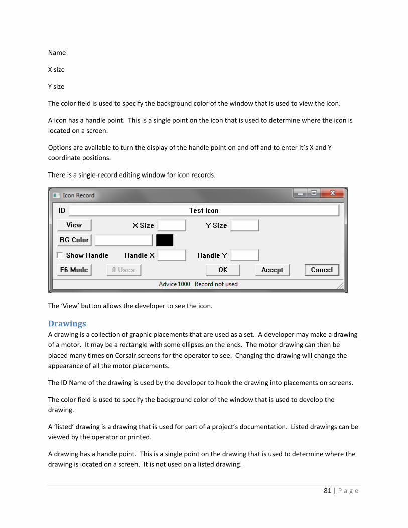
81 | P a g e
Name
X size
Y size
The color field is used to specify the background color of the window that is used to view the icon.
A icon has a handle point. This is a single point on the icon that is used to determine where the icon is
located on a screen.
Options are available to turn the display of the handle point on and off and to enter it’s X and Y
coordinate positions.
There is a single-record editing window for icon records.
The ‘View’ button allows the developer to see the icon.
Drawings A drawing is a collection of graphic placements that are used as a set. A developer may make a drawing
of a motor. It may be a rectangle with some ellipses on the ends. The motor drawing can then be
placed many times on Corsair screens for the operator to see. Changing the drawing will change the
appearance of all the motor placements.
The ID Name of the drawing is used by the developer to hook the drawing into placements on screens.
The color field is used to specify the background color of the window that is used to develop the
drawing.
A ‘listed’ drawing is a drawing that is used for part of a project’s documentation. Listed drawings can be
viewed by the operator or printed.
A drawing has a handle point. This is a single point on the drawing that is used to determine where the
drawing is located on a screen. It is not used on a listed drawing.

82 | P a g e
Options are available to turn the display of the handle point on and off and to enter it’s X and Y
coordinate positions.
There is a single-record editing window for drawing records.
The Placements button on this window opens up editing of graphic placements. This is how drawing
images are created.
Screens A screen is a collection of graphic placements that are viewed by the operator.
The ID name of a screen is used as a label to identify it.
The Escape Screen link is used to specify what screen is displayed when the operator escapes from the
screen.
Blank bottom status bar? Y/N
The color field specifies the background color for the screen.
Blank top title? Y/N
Pattern – is it a pattern?
Authority Link
Sessions List
GPS area Tag
GPS Screen Number
There is a single-record editing window for screen records.

83 | P a g e
The Placements button on this window opens up editing of graphic placements. This is how screen
images are created.
Sounds Corsair can play wave sound files when alarms or calls are tripped. This results in sound from the
computer’s speakers.
The first step is to create a folder on the computer’s hard drive to contain the sounds. A recommended
possibility is:
C:\cwaves\
This folder will contain all the wave files that the Corsair program is to use. Each of these files has a .wav
extension. Corsair has no provision for generating wave files. The sound recorder that comes with
Windows is a common way to generate them.
After the wave files are generated and placed in the proper folder the developer can start the Corsair
program. There is an option under the ‘Tools’ menu called ‘Play Sound’ that can be used to test if the
computers speakers are working properly.
Each Corsair computer must be configured to use sounds. This is done as a part of Setup/Computer
Properties. The interface tab includes an option to ‘Use Sound’ that must be checked. Below that option
is an edit box for entering the path to the folder where the wave files are. C:\cwaves\ would be a typical
entry for this option.
The next step is to create sound records in the Corsair database. This is done under
Edit/Graphic/Sounds. Each sound record gets a name. This is the identity that will be used to hook the
sounds to alarms – it is not the name of the wave file.

84 | P a g e
Zooming under each sound goes to a database of the wave files that are used for that sound. A Sound
can consist of several files that are played in consecutive order. It is possible to put a short time delay
before each file is played. Normally this timing is left at zero. It can be as short as one millisecond
(entered as 0.001s)
Wave file names can be typed into the database or found using a ‘browse’ function. The browse
function will return a full path specification to the file. The path specification in the computer properties
is put on the front of the file name that is in the database. Many times if a file name is found with the
browse the path specification will have to be removed from the file name. The computer cannot play
C:\cwaves\C:\cwaves\ding.wav.
Corsair has ‘Play’ database fields that can be used to test sounds. They are available for individual wave
file records and for sound records that include multiple wave files. The ‘Use Sound’ checkbox under
Computer Properties must be checked for these ‘Play’ files to work. The play field is activated by
arrowing to it and pressing ‘F2’ edit key. Another option is to click on the field and then click on it a
second time.
The Tools/Monitor Sounds menu option is a way to see what is happening with the sound system. It has
an option to cancel playing of the current sound.
The next step is to associate sounds with alarm and call records. Each alarm and call record has a zoom
field that allows entry of one or more sounds. A ‘Play’ field is available for testing sound.
Sound Record Fields
ID
Files Zoom
Play
RTP Tag – Request Talk Path
RTP Index #
RTP Value #
TPR Tag – Talk Path Ready Tag
TPR Index
CTP Tag – Clear Talk Path Tag
CTP Index
CTP Value

85 | P a g e
Timeout (seconds)
Sheets A user sheet is a collection of data in a row and column format for use by the operator. The developer
must specify a name for the sheet and how many rows and columns it has.
There is a single-record editing window for sheet records.
xxxx
Trends There is a single-record editing window for trend records.

86 | P a g e
The ‘Tags’ button opens a window that is used to place tags on the trend. These tags should be set up
to have trend sample data. Typically the Trend Period on the tag is set to be the same as or longer than
the width of the trend.
Scripts Scripts are programs that are created by the Corsair developer using script steps. The type of the step
determines what the step does. Different step types require different parameters. The CorsairHMI
Designer manual describes the available script step types.
There is a single-record editing window for script records.

87 | P a g e
xxxxx
Data Logs Corsair Logs are tasks that the Corsair computer can perform based upon trigger conditions. Logs can be
used to record historical data in disk files, to print, and do other tasks.

88 | P a g e
Creating a Log
Logs are created from the main menu’s Edit/ More/ Logs selection. The F4 Create key can be used to
create a log record. There are 5 zoom fields.
There is a single-record editing window for data log records.
Each of the zoom windows has a ‘trigger’ button on the bottom. These buttons are for the Corsair
developer in case he wants to manually trigger execution of the log.
The Triggers Zoom

89 | P a g e
The Triggers zoom opens a window that is used to configure the triggering of the log. Logs can be
triggered continually, upon changes in tag data, from trigger tags, or based upon the time of day.
Combinations of any or all of these triggers are possible.
The Trigger Computers button on the top of the window determines which computers in a multiple
computer system are allowed to trigger the log. A group of 4 computers may all need to look at the data
in a log file that is on a server. Each computer can view the file but only one of them is to write to it.
That computer should be the only one that is highlighted in the Trigger Computers list.
The simplest form of triggering is Always Triggering. The Always checkbox must he checked and a
nonzero time interval entered to the right of it. If it is set for ‘30s’ the log will trigger on interface
startup and every 30 seconds after that.
Data Change triggering occurs when the data in a tag changes by more than an entered value. The Tag
List button is used to enter a list of tags that are used by the log. As each tag is entered the developer
can signify if it is to be used for data change triggering. The ‘On Change’ checkbox on the Triggers zoom
window shows if any tags have been configured with data change triggering enabled.
A log can also be triggered based upon the status of up to 5 tags. Each of these tags can be entered as a
‘Corsair Triplet’ consisting of a tag, and index expression tag, and an index constant. The ‘Tag’ checkbox
on the left side of the window must be checked for this entry to happen. These tags are normally
indicators or switches as the log looks for an on-off value to determine triggering. Triggering occurs
when the tag is ‘On’ unless the ‘Invert’ checkbox is checked. Invert will cause the log to trigger when the
tag is ‘Off’.
When the tag is On (or Off if inverted) Corsair can do two possible types or triggering. Edge triggering
means that that log only triggers on the Off to On transition of the tag data. For it to trigger again the
tag must go Off and then back On. Repeat triggering happens with the Edge checkbox is not checked. It
uses a time interval. If a tag has 30 second repeat triggering the log triggers when the tag comes on and
at 30 second intervals until the tag goes off.
Post triggering is an option that can be used with tag triggering. If ‘Post’ is checked the log will trigger
one more time after all of the trigger tags go to Off.
Some logs may be set up to output pretrigger data to a log file. This is set up under the log Action zoom.
Pretrigger data is only used when the fifth of the five possible trigger tags is turned on. The find button
for this tag says ‘PTag’ instead of ‘Tag’.
There are 5 possible time of day triggers for each log. If they are checked the developer enters a start
and stop time for each one. The computers current clock time is displayed. Each time of day trigger has
an ‘Active’ checkbox that shows if it is currently active based upon the computers clock. Edge and
Repeat modes work just like with the tag triggers.
The Action Zoom

90 | P a g e
The Action zoom window for a log determines what the log does. It needs a combination of an action
and an object. The possibilities are:
Action – None
Action – Make File Object – Tag list
Action – Make File Object – Sheet
Action – Print Object – Sheet
Action – Print Object – Screen
Action – Print Object – Trend
Action – Print Object – PLC I/O
Action – Run Script Object – Script
Make File – Tag List – is one of the most common log tasks. It is used to log historical data to a CSV file.
The Tag List button is used to enter the list of tags. This is the same tag list that is used for data change
triggering. A tag list can be used for change triggering even if the Object is not Tag List.

91 | P a g e
The Run Script action can be used for time of day scheduling of a script.
A Make File action requires the specifying of a file name. The file name can be the default as shown. It
can be set to ‘Specify’ and entered. It can come from a tag triplet. It can be varied automatically based
upon month, day, or hour. The Prefix entry is typically used for a path specification. The Suffix entry is
typically used to specify an extension like ‘.csv’.
The Options group box shows other options for the log action. The ‘Timestamp’ checkbox is used with
Tag List files to place date and time fields at the start of each line of the file. This can be in the local
computer time or in GMT (UCT) time. GMT is nearly always a better option because it eliminates
confusion in the data records when changing to or from Daylight Savings Time. There are 6 date and
time fields. They are all numbers. The first is the year, the second is the month as 1 through 12, the
third is the day of the month, the fourth is the hour as 0 through 23, the fifth is the minutes from 0
through 59, and the sixth is the seconds. The seconds value may have up to three decimal places.
’23.456’ means 456 milliseconds after 23 seconds after the minute.
The normal mode for a disk file of tag data is for Corsair to create the file and then append records to it.
The ‘Renew’ option tells Corsair to create the file each time that it is triggered. Renew log files will only
have 1 record of data in them. They are designed for real-time file updates that are read by other
software.
The ‘Use Color’ option is used with print logs to tell Corsair to used color printing whenever possible
instead of Black and White.
The Data Rows option is used with Sheet File and Sheet Print actions. If Data Rows is selected Corsair
will look up from the bottom of the sheet to see how many of the bottom rows are blank. They will not
be printed.
The Other File Format radio button is not available. CSV files are the only currently supported format
for logs.
Pretrigger Data is an option with Tag List files. If it is checked and the log is triggered from the fifth of
the five possible tag triggers Corsair will attempt to insert pretrigger data into the file. This is trend data
that Corsair remembered in the form of trend samples from the time before the trigger occurred. Each
tag that is on the log must be set up with the same trend sampling period and trend interval. When the
trigger occurs Corsair ‘steps back’ into the trend data by the entered ‘Skip Interval’ time. It puts up to
the ‘Max Samples’ count of samples of pretrigger data into the log file. If Max Samples is set to zero
Corsair will insert as many pretrigger samples as it has available.
The Control Zoom

92 | P a g e
The Auto Purge Data option is currently not available for Disk File logs.
The View Zoom
The View zoom window is used to control viewing options for the log. The Operator View checkbox is
used to allow operator viewing of the log data if some form of view is available for the logs Action and
Object.
The Print Landscape checkbox is used to tell Corsair to print landscape instead of portrait if landscape
printing is available for that type of log.

93 | P a g e
The Trigger button on the bottom is used to manually trigger the log. If it is successfully triggered the
Trigger Count will increment. It then goes into a list for execution. If it executes successfully the
Execute Count will increment. The last Trigger or Execution error is shown. The Clear button clears the
error code and the counts.
The Computer Zoom
The Computer Zoom field is used to access a list of computers that can use the log. It is used in multi-
computer Corsair systems. Computers that are not selected in this list will not be able to view the logs
files.
Variable Rate Logging
CSV data files are not the most efficient way to store data. Data stored at a short time interval can
result in huge files with slow access times.
Many processes require high-speed logging while they are running but they don’t run very often. There
is no need for many data samples when the process is not running. Variable rate logging can handle
these situations.
Suppose a process employs a kiln that is used to heat material that flows through it. Logged tags
include:
Material Temperature – Ambient to 400 degrees F
Material Tons per Hour – 0 to 20.0 tph
Stack Temperature – Ambient to 600 degrees F
Draft – 0 to 10 inches water column
While the kiln is in use data is desired at a 15-second interval. It is desired to see the complete ramp-up
at the beginning of the run and the ramp down at the end. A combination of a variable logging rate
combined with pretrigger data, a posttrigger sample, and logging on change will work for this system. A
contact that shows that the combustion blower is running controls a Corsair indicator tag.
The first step is to set up a c:\clogs\ folder for storing Corsair log data. The next step is to create a log
record and go to the ‘Triggers’ zoom. Check ‘Always’ and enter ‘8h’ for the Always interval. This will
result in a minimum of 3 samples on days that the kiln does not run. Check ‘Tag’ on the fifth trigger tag.
The ‘PTag’ button can be used to select the combustion blower running indication into the Trigger Tags
column. Set the corresponding interval to ‘15s’. Check the ‘Post’ checkbox and accept the window.
Next go to the Action zoom. The Trigger Action is ‘Make File’. The file is a ‘Tag List’. The file name is
‘Monthly Auto’. The prefix is ‘C:\clogs\kiln_data_’. The suffix is ‘.CSV’. For options pick ‘CSV File’,
‘Timestamp’, ‘GMT’, and ‘Pretrigger Data’. If the pretrigger samples are at a 15-second interval a ‘Max
Samples’ value of 20 would produce 5 minutes of pretrigger data. Accept the Action window entries.

94 | P a g e
The next step is to go to the 4 tags that are going to be logged. Enter the minimum and maximum scale
for the plot of the value. Enter a sample time of ‘15s’ on each tag. Enter a trend period of ‘2h’ for 2
hours. All the tags on a log with pretrigger data need to have identical sample times.
The material Tons per Hour tag should have the units label set to ‘tph’. The integration period should be
set to ‘1h’. The Totals Units label should be set to ‘Tons’.
Next the Logs ‘Tags’ zoom is used to list the tags on the log. Each tag gets the desired pen color on the
graph. Each tag should have the ‘On Change’ set to ‘Yes’. Set the ‘Change Delta’ to 20.0 for material
temperature, 1.0 for tons per hour, 30.0 for stack temperature, and 1.0 for draft.
The ‘View’ zoom is used to check ‘Operator View’ and ‘Use for TBT and History’.
2-hour trends can be created for each tag if desired.
Now the log will always trigger every 8 hours. If the combustion blower comes on the previous 5
minutes of pretrigger data will be logged at 15 second intervals. All tags will log every 15 seconds as
long as the blower is running and for one extra sample after the blower stops. The log is also triggered
whenever a variable changes significantly.
Ethernet Objects Ethernet Objects are database records that are entered by the developer to be shown as objects on the
Communications Architecture printout.
There can be as many as three IP addresses entered for an Ethernet object. These are addresses for the
‘PLC’, ‘MIS’, and ‘Other’ networks. If they are left at 0.0.0.0 the object is not on that network. If
255.255.255.255 is entered the address is displayed as ‘Auto’. Other values are shown as normal IP
addresses.
Up to three notes can be entered on the Object to be printed on the architecture.
SQL Paths There is a single-record editing window for SQL Path records.

95 | P a g e
xxxxx
FTP Paths
There is a single-record editing window for FTP Path records.
xxxxx

96 | P a g e
Driver Paths
Xxxx
Local and Global Database Views
Corsair uses a treelike family structure for database records.
Driver 1
PLC A
Tag A1
PLC B
Tag B1
Tag B2
Driver 2
PLC C
Tag C1
Tag C2
There are two driver records. The first has two PLC records titled A and B. The second has a single PLC
record titled C.
A developer may be looking at the Driver 1 record. If he zooms on the data source zoom field he sees
PLC A and PLC B. If he goes to the Driver 2 record and does the zoom he sees the PLC C record. The
data source sheets that he sees are ‘Local’ views that are under the driver. They only show the data
sources for the driver that started the zoom.
If the developer chooses the ‘Edit’ ‘Data’ ‘Sources’ menu option he sees PLC A, B, and C. This is a
‘Global’ view of the data sources.
The same system of local and global views of data sources also applies to local and global views of tags.

97 | P a g e
When development data is being shown with a local view a menu option is available to switch the
display to a global view. Another option switches it back to local.
Creating Graphics The ‘Edit’ ’Graphics’ ’Screens’ menu option opens the development sheet that creates screens. Zooming
on a screen record opens graphic development of that screen. The same thing is true for drawings.
Objects that are shown on Corsair screens or drawings are called ‘placements’. These are the ‘graphics
primitives’ of the Corsair system. Placements are created by moving the cursor to a location on the
screen and pressing the F4 ‘Create’ key. This opens the placement type selection window. The ‘type’ of
a placement determines what the operator sees when the placement is shown on the screen.
The developer must select a placement type. This type cannot be changed after the placement is
created. If a wrong type is selected the placement must be deleted. The next step is the placement
action window.

98 | P a g e
The developer must select the action for the placement. The ‘action’ determines what happens when
the operator clicks on the placement. The available actions are different for screen and drawing
placements.
The type of a placement and its action are independent. Each type can have any allowed action.
The developer should select an action. Now he sees the placement editing window. The appearance of
this window changes based upon the placement type and action.
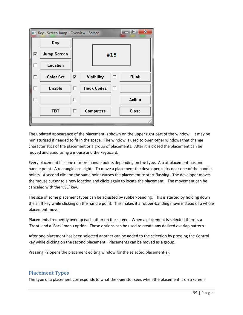
99 | P a g e
The updated appearance of the placement is shown on the upper right part of the window. It may be
miniaturized if needed to fit in the space. The window is used to open other windows that change
characteristics of the placement or a group of placements. After it is closed the placement can be
moved and sized using a mouse and the keyboard.
Every placement has one or more handle points depending on the type. A text placement has one
handle point. A rectangle has eight. To move a placement the developer clicks near one of the handle
points. A second click on the same point causes the placement to start flashing. The developer moves
the mouse cursor to a new location and clicks again to locate the placement. The movement can be
canceled with the ‘ESC’ key.
The size of some placement types can be adjusted by rubber-banding. This is started by holding down
the shift key while clicking on the handle point. This makes it a rubber-banding move instead of a whole
placement move.
Placements frequently overlap each other on the screen. When a placement is selected there is a
‘Front’ and a ‘Back’ menu option. These options can be used to create any desired overlap pattern.
After one placement has been selected another can be added to the selection by pressing the Control
key while clicking on the second placement. Placements can be moved as a group.
Pressing F2 opens the placement editing window for the selected placement(s).
Placement Types The type of a placement corresponds to what the operator sees when the placement is on a screen.

100 | P a g e
Address
Xxx
Arc
Xxx

101 | P a g e
Bar Graph
Xxx

102 | P a g e
Checkbox
Checkbox placements look like Windows checkbox controls. The check mark can appear or disappear
inside a box. Corsair checkboxes do not support text labels on the right side of the box. This is done with
separate text or value placements.

103 | P a g e
Corner
Corner placements are not implemented at this time.
Drawing
Drawing placements are used on screens to show Corsair drawings. Each placement needs to be linked
to a drawing.

104 | P a g e
If the drawing is ‘Fixed’ it is shown on the same position on the screen as it was developed in the
drawing window. In that case the handle point of the drawing and the handle point of the placement
are not used. If it is ‘moveable’ the handle point of the drawing is placed on top of the handle point of
the placement.
Ellipse
Ellipse placements can be used to draw circles if the height and width are the dame.
The primary handle point of an ellipse placement is the center.
Frame
A Frame placement is used to mark divisions of other placements into rectangular frame ‘cells’. The
number of cells is defined by the frames row and column count values. A row count of 2 and a column
count of 3 defines a 9-cell frame.

105 | P a g e
The primary handle point of a frame is the top left corner.
Icon
Xxx
Key
A Key placement is designed to look like a Windows button.

106 | P a g e
The label text can appear on multiple lines. The simplest method is comma separation. The developer
types in
First Line,Second Line
If a comma is to appear on the button the line can be marked with quotes.
“First Line, Continued”,”Second Line, Continued”
The Font button opens the font selector. The Default Colors button is used to initialize a suggested color
combination.
Line
A line placement can consist of up to 10 segments. 10 segments have 11 handle points.

107 | P a g e
The X and Y positions are the handle points of the line. They may be adjusted here but it is usually
easier to adjust them by rubber-banding with the mouse cursor.
A line with a thickness of 1 can have any of the style options from Sold to Dash Dot Dot. Thicker lines
can only have the Solid style.
Picture
Picture placements are used to show a picture corresponding to the current value of a tag. The picture
selection depends upon the type of the tag. Currently picture placements are only defined for HOA tags.

108 | P a g e
Pipe
Pipe placements are not implemented at this time.
Point Name
Xxx
Polygon
A polygon is a multi-sided placement that can be created in any position. It can have as many as 10
sides. A 10-sided polygon has 10 handle points.

109 | P a g e
Rectangle
A rectangle is a 4-sided placement that is aligned straight up and down on the computer screen.

110 | P a g e
The primary handle point of a rectangle is the top left corner.
Rounded Rectangle
Xxx

111 | P a g e
The primary handle point of a rounded rectangle is the center.
Spline
Xxx

112 | P a g e
Tank
A tank placement is a representation of a barrel-shaped liquid container. A vertical tank stands on an
end. A horizontal tank is laying on its side.

113 | P a g e
Text
A text placement shows an unchanging text label on the screen.
The nine justification radio buttons control how the text label is arranged around the handle point. If
the upper left button is selected the text is shown to the right and below the point.
Trend
A trend placement specifies a rectangular region for the computer to display a data trend.

114 | P a g e
Value
A value placement shows varying text on a screen. The text shows the value of a tag.
The nine justification radio buttons show how the value text is arranged around the handle point. If the
upper left button is selected the text is shown to the right and below the point.

115 | P a g e
Placement Actions A placement’s action determines what happens when the operator clicks on it with a mouse or touches
it on a touchscreen. The action may also determine when the placement is visible and when it blinks.
Alarm Action
The Alarm action must be linked to an alarm.
The status of the alarm controls the placement’s visibility and blink properties. If the alarm is clear the
placement is invisible. If the alarm is unacknowledged the placement blinks.
Call Action
The Call action works just like the alarm action except that is must be linked to a call.
Display Action
The display action is the simplest action. The placement is shown if the visibility conditions permit. It
cannot be clicked on by the operator.
Entry Action
xxxx
I/O Jump Action
xxxx
Log Jump Action
xxxx
Source Comms Action
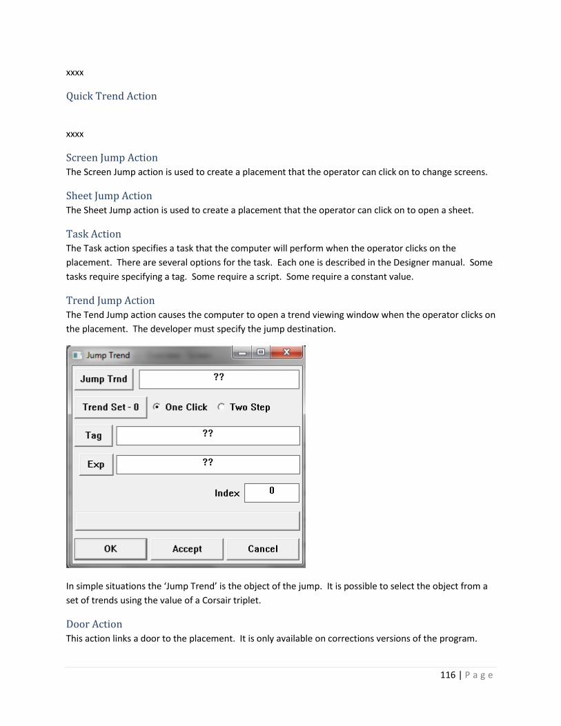
116 | P a g e
xxxx
Quick Trend Action
xxxx
Screen Jump Action
The Screen Jump action is used to create a placement that the operator can click on to change screens.
Sheet Jump Action
The Sheet Jump action is used to create a placement that the operator can click on to open a sheet.
Task Action
The Task action specifies a task that the computer will perform when the operator clicks on the
placement. There are several options for the task. Each one is described in the Designer manual. Some
tasks require specifying a tag. Some require a script. Some require a constant value.
Trend Jump Action
The Tend Jump action causes the computer to open a trend viewing window when the operator clicks on
the placement. The developer must specify the jump destination.
In simple situations the ‘Jump Trend’ is the object of the jump. It is possible to select the object from a
set of trends using the value of a Corsair triplet.
Door Action
This action links a door to the placement. It is only available on corrections versions of the program.

117 | P a g e
Clicking on the placement ‘hooks’ the window to the placement. At that time the placement’s hook
code values are transmitted. The operator can see his F1-F4 keystroke options on the status bar on the
bottom of the screen.
When this action is used for a placement like an ellipse a color list can be specified. If no tag is tied to
the list the color selection comes from the status of the door. When it is unsecure the 0 (zero) colors are
used. When it is secure the 1 (one) colors are used. The same thing is true for drawing and icon lists. In
each case if the list is indexed by a tag the value of that tag is used instead of the door status. This
makes it possible to have more than two items in the list.
Door Command Action
This action enables the operator to execute a command for a door. It is only available on corrections
versions of the program.
The developer must specify a door and which command to execute. The available commands emulate
the F1, F2, F3, F4, or ‘E’ key.
Developing User Sheets The ‘Edit’’More’’Sheets’ menu option opens the development sheet that creates user sheets. After a
sheet record is created a number of rows and columns must be entered. Zooming on the sheet record
opens an operator view of the sheet. If development is turned on the developer can start to define the
contents of the sheet’s cells.
The first set is to put a label on top of each column. Arrow to a cell on the column and press the ‘L’ key.

118 | P a g e
Labels can be static or dynamic. A static label is fixed text that does not change. A dynamic label comes
from the value of a tag.
[Note – as of this writing labels can only be static]
Sheet cells are identified with designations that use a letter for the column and a number for the row.
Starting at the top left of a sheet the cells are:
A1 B1 C1 D1
A2 B2 C2 D2
A3 B3 C3 D3
A4 B4 C4 D4
If the ‘Development’ menu option on a sheet is checked the cell designations are shown for all blank
cells.
The contents of a cell are edited by arrowing to the cell and pressing ‘F7’ or ‘Z’ to zoom.

119 | P a g e
The definition of a cell includes a type. The radio buttons on the top of the window set this type. It also
includes a place near the bottom to enter a repeat count number. If the repeat count is zero the
definition only applies to that cell. If it is nonzero the definition also applies to that many cells
immediately below it. A definition with a repeat count of 4 applies to a total of 5 cells.
A ‘blank’ cell has no contents. Blank cells cannot have a repeat count.
A ‘text’ cell requires the developer to enter a text label. This label is what will appear in the cell. If there
is a nonzero repeat count each of the repeat cells will show the same label.
A ‘constant’ cell requires the user to enter a number. That number will appear in the cell. If there is a
nonzero repeat count numbers will appear in the repeat cells. Each cell uses a number that is equal to
the cell above it with the shift value added. If the constant is 2, the repeat count is 4, and the shift is 3
the 5 cells from top to bottom will read 2, 5, 8, 11, and 14.
A ‘tag’ cell is used to show the value of a tag.

120 | P a g e
Insert more stuff here
A ‘Line’ cell contains a horizontal line. Line cells are used to divide sections of the sheet.
Creating I/O Modules
Xxxxxxx
Developing with Corsair Blocks
Note – custom program blocks are not implemented at this time!
The Corsair program uses program blocks to perform calculations on tag data. A block is defined in one
place. Each time that the block is used is an ‘instance’ of that block. A change in the definition of a block
applies to all instances of that block.
Blocks come in two types, standard and custom. A standard block comes with the Corsair program.
Standard blocks cannot be changed by the Corsair developer. Custom blocks are blocks that can be
defined and changed by the developer.
Standard blocks must be installed into Corsair application before they can be used. When the
development level is set to ‘administrator’ the Tools/Expert/Block menu options leads to a window with
two lists. The left-side list has the currently installed standard blocks. The right-side list has the currently
configured custom blocks. Standards are installed with the Standard/Install menu option. The standard
block list must be empty before this installation can occur. This can be done from the ‘Standard/clear
and Install’ menu option. The CAP Corsair application file must be saved after standard blocks are
installed.
When a new version of the Corsair program is released the database checking utility will check to see if
the installed standard blocks match the new version. If they do not match a system error will prompt the
developer to clear and install the standard blocks again. This does not require any other changes to the
users application file.
Custom blocks are created using normal sheet-style editing of the custom block database. This is done
with the Edit/More/Custom Blocks menu option. Pressing the ‘F4’ (create key) inserts a new block
record into the database. There are 5 zoom fields associated with each custom block. They are used for

121 | P a g e
block variable definition, block parameter definition, block initialization code, block forward code, and
block reverse code.
The block variable definition window allows the developer to enter a purpose for the block. Each block
can have up to 10 internal variables named ‘VA’ through ‘VJ’. These variables are local to each instance
of the block. They are not global. Each time a block instance is created it has its own copy of these
variables that no other block can access. Variable definition includes a size for variable. If it is assigned a
size of ten it is an array with ten values using indexes from 0 through 9. Each variable also has a type,
which are the same as those used by Corsair tags. A data format is used for some tags and a string
length is used for some tags.
There are a maximum number of bytes of data that can be used for block variables. It is shown on the
bottom of the block variable definition window along with how many total bytes the configuration uses.
If the total exceeds the maximum the variable configuration must be changed.
The block parameter definition window allows the developer to define parameters that are used by the
block. The ‘main’ parameter is the tag that the block is assigned to. It can get a label. The 10 parameters
that are assigned with a block instance are called ‘PA’ to ‘PJ’. A descriptive label can be put on each
parameter. Each parameter also needs a type and sometimes a format.
Sometimes a block may need more data space than what is available with internal block variables ‘VA’
through ‘VJ’. Tags can be sized as very large arrays and then assigned as block parameters to solve this
problem. A different tag may need to be created for each instance of the block. Use of the block
variables whenever possible simplifies the development task and avoids unintended data collisions.
The code for each block is divided into 3 different sections, Initialization, Forward and Reverse.
Initialization code is executed once a short time delay after the Corsair program starts interface
operation. After the initialization code has been executed for each block the computer continuously
executes the Forward code. The Reverse code is executed once each time that the operator enters a
value into a tag that has a block assigned to it.
Most standard blocks do not have any code that the developer can see. Their code is contained in the
Corsair program in a compiled form.
The window that is displayed from the Tools/Expert/Block menu option allows the developer to zoom in
on any of the 5 zoom fields for any standard or custom block. Configuration of standard blocks cannot
be changed. The Standards/Clone to New Custom menu option on this window is used to clone a
standard block to anew custom block. It can then be modified just like any other custom block.
Standard or custom blocks can be assigned to a tag, alarm, or call tags. The tag must be a memory tag –
it cannot be resident on a PLC or on a device(dave read this line). Memory tags can be displayed by
picking the Edit/Data/Alarms followed by View/Local shows alarms that can be the result of block
calculations. The same thing is true for calls.
122 | P a g e
Let’s assume that a PLC has a 5 temperature values that are in Centigrade degrees. The interface needs
to display them in Fahrenheit. The ‘MC Plus B’ standard block was designed for this purpose. The first
thing to do is install standard blocks into the database. The Tools/Expert/Blocks window should show
that the standard has been installed. The next step is to create a communication Driver record that is
the proper type for the PLC. This is done under Edit/Data/Drivers. Creating the driver gives the
developer a zoom option for PLC’s. Zooming into this allow creation of 5 tags. These tags represent the
raw vales in Centigrade degrees. Each of these tags should get a PLC address that is usable by the driver
to read in the data.
The ‘MX Plus B’ block is not installed on the PLC raw value tags. 5 more tags must be created for the
scaled Fahrenheit values. This is done by going to Edit/Data/Devices and creating the tags. These tags
are computer-memory and not PLC resident. Near the right side of the development sheet there is a
field named ‘Block ID’ The tag ‘MX Plus B’ should be typed in here. If this name exactly matches the
name of either an installed standard or custom block an instance of the block is created. The two zoom
fields to the right of the Block ID field pertain to this instance of the block. They are for block parameter
assignment and block variable monitoring.
The Block Parameter Assignment window is used to define the tags that one instance of the block uses.
Labels for the 10 parameters are shown. Each parameter can be assigned either a constant or a tag. In
this example the PA parameter corresponds to the input to the block. It gets the tag of the raw
centigrade value. The PB parameter sets a constant value of 1.8. The PC parameter gets a constant value
of 32.
The block parameter assignment window has a ‘Details’ button that lets the programmer see an
unchangeable summary of the configuration of the block parameters.
The block variables monitor window allows the developer to see current values of the variables inside a
block instance. The top of the window has 10 radio buttons for block variables VA through VJ. Variables
that have been defined to have a size of zero in the block configuration are grayed-out. Selecting a radio
button causes a listing of the values of the indexes of the variable to appear. The type, data format, and
string length of the variable are also shown.
The block variables monitor window has a ‘Details’ button that lets the programmer see an
unchangeable summary of the configuration of the block variables.
The Corsair Select and Replace System Corsair includes a system that the developer can do to speed up many of the tasks that are involved
with making a model file. The Select and Replace system is a way of manipulating the ID text on
database records. It is especially valuable when there are similar elements in the database, like a facility
with several identical buildings. If the developer understands how to use Select and Replace and does
the proper planning, he has very little work to do after he has finished the first building. The key is to
make sure that the labels used for record ID are compatible with Select and Replace.

123 | P a g e
The system usually starts with the developer entering in 3 pairs of Select and Replace entries. Each pair
is called a ‘rule’.
A Select entry describes a pattern for a label. When a label is compared to a valid Select entry the
computer can decide if the label matches that entry. A data source may have 100 tags on it. 73 of them
might match the Select entry. The remaining 27 wouldn’t match it.
A Replace entry describes a pattern to change a label. For each tag that matches the Select entry of a
rule the computer will change the tag according to the pattern of the Replace entry. A complete
operation usually involves 3 rules.
Rule 1 Rule 2 Rule 3
Select 1 Select 2 Select 3
Replace 1 Replace 2 Replace 3
For each label that is in the specified set the computer first goes to Rule 1. It checks for a valid Select 1
entry. If the Select 1 entry is invalid it goes on to Rule 2 and checks for a valid Select 2 entry.
If the Select 1 entry is valid the computer checks to see if the label is a match for Select 1. If it is not a
match it goes on to check the validity of the Select 2 entry.
If the Select 1 entry is a match the computer checks to see if the Replace 1 entry is valid. If it is not valid
that label is done and left unchanged. If the Replace 1 entry is valid the computer does the replacement
specified by the rule and that label is done.
Most of the windows that use the Select and Replace system show the developer a ‘Can’ and ‘Can’t’
count before he activates the rules. This allows him some opportunity to evaluate if the rules will do
what he wants them to do.
All Select and Replace rule entries consist of at least one section. An example Select is the string ‘abc’.
This Select has one section containing 3 characters. It is an example of a ‘literal’ section. The label must
match the literal section. Corsair uses case-insensitive selection. That means the following labels will
match this Select.
‘abc’ ‘Abc’ ‘ABC’
The system uses 6 special characters in the Select and Replace entries. They are:
Vertical Bar |
Asterisk *
Question Mark ?
Number Sign #

124 | P a g e
Caret ^
Tilde ~
It is possible to use these characters in Corsair ID labels but the practice is strongly discouraged.
The first special character is the bar. It is used as a section divider. Every entry has at least one section.
The Select ‘abc’ is equivalent to the Select ‘a|b|c’. The first select has one section with three characters.
The second select has three sections which each have one character.
If the Asterisk character is the first character in a section it serves as a ‘wild-card’ that represents a
group of characters. The group could be empty or it could be quite long. The Select ‘A|*’ matches any
label that begins with the letter ‘A’. A single ‘A’ by itself matches this Select.
Rules match up sections between the Select and Replace entries to see how the replace action is going
to work. A possible rule could be:
Select ‘A|*’ Replace ‘B|*’
This rule would select any label beginning with the letter ‘A’ whether it had anything else after it or not.
It would change the leading ‘A’ to a ‘B’.
The Question Mark is used as a single-character wildcard. It matches exactly one character. A rule could
be:
Select ‘A|?’ Replace ‘B|?’
This rule selects any label beginning with the letter ‘A’ that is exactly two characters long. It changes the
leading ‘A’ to a ‘B’.
This is another possibility:
Select ‘AB|*|?’ Replace ‘C|*|DE’
This rule selects any label that begins with ‘AB’ and has at least one more trailing letter. The leading ‘AB’
is replaced with ‘C’. Any characters in the middle are unchanged. The trailing single character is
replaced with ‘DE’.
The Asterisk and Question Mark characters only count as wild cards if they are the only item in the
section. The Select ‘AB*|?E’ has no wild cards. It will only match the string ‘AB*?E’. A special case
occurs when the developer wants to have a literal section consisting of only an Asterisk or Question
Mark. This is signified by a repeated character.
Select ‘AB|**|CD|?’
This select matches labels beginning with ‘AB*CD’ followed by exactly one more character.

125 | P a g e
The Number Sign is used to signify a section with a number. The number cannot contain plus or minus
signs or a decimal point.
Select ‘AB|#|*’
This Select will match ‘AB0’ or ‘AB2789Z’. It will not match ‘ABC29Z’.
The Number Sign must be the first character in the section to signify a number – otherwise it is part of a
literal.
There are additional options for Number sections of Replaces. These options are not available for
Number sections of Selects.
‘#04’ Leading zero pad to get a total of 4 digits
‘#+3’ Add 3 to the existing number
‘#+’ Add 1 to the existing number
‘#-2’ Subtract 2 from the existing number
‘#-‘ Subtract 1 from the existing number
‘#05-1’ Subtract 1 from the existing number and leading zero pad to get 5 digits
‘#03+’ Add 1 to the existing number and leading zero pad to get 3 digits
Leading zero padding is used to force numbers to be a fixed length. It guarantees that labels will be
alphabetically sorted in the proper order.
Empty sections can be used to remove portions of labels.
Select ‘A|?|*’ Replace ‘A||*’
This rule takes any 2-character or longer label that begins with A and removes the second character.
Empty sections are not allowed in Select entries.
The Caret character is used as a ‘Command’ indicator in a section of a Replace. The next character
determines the type of command.
^L Lower Case
^U Upper Case
^M Mixed Case
^I Insert

126 | P a g e
The L, U, M, and I can be in upper or lower case. Upper is the preferred syntax.
For the Lower, Upper, or Mixed case commands only the Caret and the letter appear in the section. The
computer does the desired case correction on that section.
An insert command section consists of the Caret, the I, and some literal text. The text is inserted
between two other sections. This is an exception to the rule that the number of sections in the Select
entry must equal the number of sections in the Replace entry. Insert sections to not have corresponding
sections in the Select entry.
Numbers may be inserted as text like in the section ‘^I2’.
The Tilde character is reserved for future use.
Database Record Import and Export A Corsair developer may need to create a large quantity of tags, alarms, calls, or doors. It may be more
efficient to create these database records outside of Corsair using a spreadsheet program. The data can
be saved in a CSV (comma separated variable) formatted file. The file data can then be imported into
Corsair. The opposite operation is also possible where data is exported from Corsair to a CSV file.
The format of the file will vary based upon the record type. A file of tags has different column types
than a file of doors. The developer can see the format for the files from the ‘Help’’Program
Information’’CSV Fields’ menu option. This opens the Import/Export Fields window.
Every field of each type of file is described by a tree view here. The tree can be printed for paper
documentation.
Corsair reserves the right to change the file formats as new features appear in the program. A data file
produced for one version of the program may be incorrect for another version. In each case the
Import/Export Fields window will show what is correct for that version of the program.

127 | P a g e
Importing a data file involves the ‘Edit’’Model Data’’Imports’ menu path.
The CSV button on the left side opens a file name picker control that can be used to put the file name in
the edit control on the center of the window. At that time the buttons for Tags, Alarms, Calls, and Doors
will appear. The developer must select the button that is correct for the data in the file. It opens the
CSV data import window.
This window allows the developer to see the data from the file before he elects to create the records.
Fields that have an error are shown in color to warn him of potential problems with the file. Ideally all
of these errors are resolved before the import happens. Often the answer is to edit the file in the
spreadsheet software and save the results. Closing and reopening the CSV Data Import window will
cause it to try the new version of the file.
Some potential import errors are avoided by changing data in the Corsair model database. The
developer may be trying to import a tag named ‘Tank Level’ when Corsair already has a tag by that
name. He cannot edit the file data from the window but he can leave it open while he changes the
name of the existing tag to ‘Old Tank Level’. The ‘View’’Recalculate Errors’ menu option will cause
Corsair to recheck for the name collision.

128 | P a g e
When the developer wants to import the record data he picks the ‘Import’’Import’ menu option. If
there is no problem the CSV Data Import window will close automatically. Problems will result in an
error message.
Corsair’s default behavior is to not do the import if any problem exists with the file data. Advanced
developers can override this and import from imperfect data. This is done by adjusting two menu
options that are under the ‘Import’ menu item.
The first option is the ‘Warnings’ option. It defaults to ‘Abort Import’ where nothing is imported if any
kind of warning exists in the data. The ‘Discard Line’ option causes Corsair to not import from any line
that has a warning on any of its fields. The ‘Ignore’ option instructs Corsair to accept every line and do
the best that it can with the imperfect data.
One type of warning is when there is an item (Tag, Alarm, Call, or Door) already in the Corsair model
database that has an ID name identical to a line of the import file. Special control options apply to these
‘Duplicate’ warnings. The ‘Abort Import’ default behavior is to not import anything if a duplicate exists
anywhere in the file. The ‘Discard Line’ option causes Corsair to not import from any line that has a
duplicate. The ‘Replace’ option causes Corsair to import the new record, change all links from the old
record to the new one, and then delete the old record. The ‘Append’ option causes Corsair to import
the new record. The developer will then have to manually resolve the name collision.
Exporting data to a file involves the ‘Edit’’Model Data’’Exports’ menu path. Exported files will contain
more fields than what are required for import.
CSV Data Import Data is frequently kept in disk text files in a CSV – comma separated variable – format. The file consists
of a number of ‘rows’ which may also be called ‘records’. Each row has one or more columns which are
also called ‘fields’. Typically each item is surrounded by double quote marks and the columns are
separated by commas. An example of the contents of a CSV file is:
“R1C1”,“R1C2”,”R1C3”,
“R2C1”,“R2C2”,”R2C3”,
“R3C1”,“R3C2”,”R3C3”,
CSV data import is a tool within the Corsair program that is used to import data from a CSV file into
Corsair tags. The tags can be memory tags in the Corsair database or they can be located on a data
source like a PLC. The tool can do import for as many as three tags at one time. The operation can be
performed multiple times on different columns of the same CSV file to load many tags.
The first step before doing CSV import is to verify that the developer has administrative privileges. The
status bar on the main Corsair windows should show ‘Dev: Admin’ on the lower right corner. If it does
not, the level can be changed through the Users/ Change Level menu option.

129 | P a g e
The next step before data import is creation of all the necessary tags and locating them on the correct
data sources with correct addresses. Most types of data sources can be used but frequently these tags
will be created on a Modbus Memory Map data source. The imported data for a memory map is packed
into a binary file where Corsair can access it far more efficiently than it can access a CSV file.
After the tags are created the developer must run the Corsair interface. This means that the interface
check box is checked so that Corsair can perform whatever communications tasks are required by the
import.
Now the developer must view the contents of the CSV file using the Corsair CSV file viewer. Pick View/
Files/ CSV File Viewer from the menu. A dialog box appears that allows selection of a file. When the file
is open the developer can see the data items that are in it and how many rows and columns are present.
One data item is shown in inverse (reverse) colors. This item is in the ‘current’ row and column position.
The arrow keys can be changed to the current position. Typically the developer will arrow to the first
item that he wants to import. He must not have the View/ Auto Refresh menu option checked.
The Edit/Import menu option is used to open the CSV data import window. This window has group
boxes containing controls for the import of data into 3 different tags. Below them on the lower left is a
button that is labeled ‘Import’ if an import is ready. If it is not ready it shows an error number that you
can click on for an explanation of the error. The current row and column number of the CSV Viewer and
the row and column totals are shown in boxes along the bottom of the CSV Import window.
Data Import Tag Controls
The first step to set up a tag for import is to check the ‘Tag’ check box. Next the ‘Find’ key is used to
select the name of a tag into the next box. This box starts out with two question marks. It changes to
the tag name as soon as one is found. The button to the right of the tag name is blank unless there is an
error in the import setup of the tag. If this is the case an error number is shown and clicking on the
button brings up an explanation of the error.
The ‘Current’ checkbox is only offered on the first tag of the three. It is checked if the data import of the
tag is to begin at the current row and column position on the CSV file viewer. The row and column
boxes for the tag cannot be entered if this option is checked. Unchecking it allows the row and column
to be entered like with the other 3 tags.
The ‘Index’ number is the index of the first element of the tag that is to receive import data. If the tag
has an array size of 20 valid index values can range from 0 to 19. Most imports will use zero values for
the Index entry.
The ‘Count’ number is how many consecutive indexes of the tag will be imported starting at the entered
row and column position and working down the column.
Assume the following entries:
Row 2 Colum 3 Index 4 Count 3

130 | P a g e
Corsair will do the following import:
Row 2 Column 3 to index 4 of the tag
Row 3 Column 3 to index 5 of the tag
Row 4 Column 3 to index 6 of the tag
Corsair will check all row, column, index, and count values for validity before an import can begin with
errors showing on the buttons on the CSV Import window.
Data Import Type Conversion
The raw data coming in from the CSV file has a data type of string. This is converted to the proper type
and format for the tag. In some cases this conversion may not yield the proper results. The ‘Input Type’
check box on each tag group allows the developer to select a tag type and format for an intermediate
result. When it is used the data is converted from the string that is in the CSV file to the type and format
of the intermediate result and then converted to the type that is required by the tag.
CSV Data Import for the GPS Markers Block
Data import is frequently needed for the GPS Markers Block. The CSV file data may be in three columns
– latitude, longitude, and a name for each marker. This data is imported into three tags that are located
on a Modbus Memory Map file. If there are 100 markers the latitude and longitude tags should have a
size of at least 100 and the name string tag should have a size of at least 101. The Latitude and
Longitude tags should be 64-bit integers with Latitude and Longitude formats. The Marker names tag
should be a string with a length greater than or equal to the longest string to be imported. Each of the
tags should have a proper Modbus address and the Memory Map data source should be set to ‘Real?
Yes’ before the import is attempted. Since imports must be performed with the Interface running
Corsair will write the data to the memory map file.
It must be noted that the GPS marker name tag uses index 0 for the marker name if no valid marker is
found. Index 1 of the name tag corresponds to the first latitude and longitude position. Because of this
the Index entry for the import of the latitude and longitude tags should be zero and one for the marker
names tag.
The latitude and longitude may be in decimal degree format in the CSV file. If this is the case the Input
Type option needs to be checked with a suggested type of Double Float and a format of -3.7. Corsair will
convert the string from the CSV file to a Double Float and then to its internal latitude and longitude
format.
CSV Data Import for the GPS Areas Block
The data import requirement for the GPS Areas block differs from the GPS Markers block since the
latitude and longitude tags are grouped into 4 indexes for each area. If there are 100 areas the latitude

131 | P a g e
and longitude tags would have a size and an import count of 400 starting at index 0. The string tag
would have a size of 101 and an import count of 100 starting at index 1.
DXF Import DXF files are generated by computer drafting programs. The Corsair program has a limited ability to
read .DXF files and translate them to drawing placements. The developer imports the DXF into a DXF
tree format. He can then isolate sections of the drawing to create drawing placements. The tree data
can be saved in a separate file to avoid having to import a second time at a later date. DXF import works
best on a computer with more than one monitor.
DXF import starts at the import window.
The DXF button is used to browse for DXF files to be put in the edit box. If a file name is entered the
‘Lite’ and ‘Full’ buttons will open the file for import. The ‘Lite’ button opens the DXF expert without
loading the tree control. The ‘Full’ button opens the DXF expert using the tree control. DXF import can
take a lot of time with several minutes possible for large files. For an initial import of a large file the Lite
option is recommended. The data can then be saved as DXF tree data.
If the developer already has a DXF tree data file he can click on ‘Lite’ or ‘Full” with no name in the edit
box. After he gets to the DXF expert window he can then load the tree file.

132 | P a g e
The DXF expert window consists of a tree control on the left side and other controls on the right side.
The tree control will be empty if the window was opened with the ‘Lite’ option.
Every DXF file consists of a number of elements called ‘Entities’. They are listed in the Entities section of
the tree control. Corsair cannot work with all the possible types of DXF entities. An entity that Corsair
cannot use is an ‘Undrawable’ entity. Each drawable entity can be ‘Enabled’ or ‘Disabled’. Enabled
entities are used to create Corsair drawing placements. Disabled entities are kept in the tree data but
are not used for placements.
The developer can preview imported DXF data using the ‘View’ menu options. If he picks ‘View’’All’ he
can see all of the drawable entities that fit onto the preview window. Four numbers are used to scale
the preview window. They are LLX (Lower Left X), LLY (Lower Left Y), URX (Upper Right X), and URY
(Upper Right Y). Based upon these 4 values entities can be On-Screen and seen in the preview window,
Off-Screen and not seen, or Partial and partially seen. The DXF expert window shows totals for each
type.
On the preview window disabled entities will show in a light gray. Other entities will show in one of the
4 import grouping colors. These are four colors that can be used by the developer to mark different

133 | P a g e
groups of entities. They are Black, Red, Green, and Orange. These colors are not used for Corsair
drawing placements that are created from the DXF expert. They are only used to segregate entities as
the developer works with the DXF tree to create drawings. The color that is normally used for created
placements is shown on the bottom right side of the expert window. The ‘C’ button is used to open a
color selector to aid the developer in finding the color that he wants.
While the developer is looking at the preview window he can use the L(eft), R(ight), U(p), and D(own)
buttons to change the scaling numbers that define what he sees on the window. The Zoom In and Out
buttons perform those functions. Wide, Thin, Tall, and Short should be used with some more caution as
they are more likely to distort the horizontal and vertical aspect ratio of the drawing entities. With most
Corsair systems the drawings are not to scale and the developer is free to adjust them for the best
appearance.
The Preview window comes in 6 different versions. The Result version shows what the proposed Corsair
drawing will look like. It does not show disabled elements. The other versions of the preview window
show disabled elements in light gray. The developer can preview all of the grouping colors or only one
of them as desired.
The Target menu item controls how the drawing placements are created. The developer can select
using all entities, or just the entities from one of the color groups. In every case undrawable and
disabled entities are not used. The expert can create a new Corsair drawing. He can also replace the
current contents of an existing drawing or append to the contents of that existing drawing. The line
color for the imported placements will be the color that is entered at the bottom of the window or
(Future) color information from the DXF file.
The Target button is used to open a Corsair selector to enter an existing drawing for a replace or append
operation. The button on the bottom below the target button is used to perform the operation. The
View/Target menu option lets the operator see the drawing before and after the placements are
created. The View/Drawings menu option opens editing of drawing records. The View/File Text menu
option opens the original PDF file to allow the operator to explore it’s contents.
The develop can select an entity from the tree control by clicking on it. He can then eliminate (delete) it,
set its grouping color, and enable or disable it from the buttons on the right side. The selected entity
will flash on the preview screen. Another option is to flash all entities on the preview screen that are on
the same DXF layer as the selected element.
Many menu options are available to set options on multiple entities at the same time. Corsair does not
allow drawing placements to be created if any of them are off-screen. The ‘Visibility’’Disable’’Off-
Screen’ menu option can take care of these situations.
The ‘Scale’ menu has options to change the scaling numbers to fit groups of entities to the Corsair
screen. When a drawing is first loaded it is scaled using the drawing extents values from the DXF file. A
menu option can return the scalings to these values. There are orientation options for the imported
drawing.

134 | P a g e
If a developer is looking at a portion of a drawing with a desired scaling and orientation he can mark that
position with the ‘Remember As’ options. The values will be returned with the ‘Go Back to’ options.
The ‘Tiny Moves’ menu item is to switch the image moving and zoom buttons to a much finer resolution
for precise positioning of the imported image.
Corsair Micro-CAPs A CAP file is a CorsairHMI application database. It may contain several inter-linked databases of drivers,
screens, tags, and so on. Most CAP files contain sufficient information that they provide a complete
database for the Corsair program to run a customer’s application. Micro-CAPS are also CorsairHMI
application database files. They use the exact same file format and file extension as any other
CorsairHMI CAP file. They may be complete runnable applications but generally they contain far less
information. A Micro-CAP may contain only a single screen and its placements, or just a drawing, or just
a PLC with a number of tags on it. The definition of a Micro-CAP is that it is a CAP that was ‘extracted’
from another CAP. Extraction is the process of removing database records to create a smaller file that
contains a sub-set of the data that was in the original file. The primary purpose of Micro-CAPS is to
provide the CorsairHMI developer with a library of database components that he can combine to serve
as a basis for his application.
Database Extraction
Database Extraction is the process of deleting records out of a CorsairHMI CAP to prepare it to be saved
as a Micro-CAP for library purposes. One way that this can be done is manually with the developer
deleting records as desired. He then saves the data using the ‘Save As’ menu option. This approach only
works well with small databases. The developer must be careful not to use the ‘Save’ menu option as
that would result in the extracted database being also stored in the original file. There is a developer
preference to enable automatic saving of the CAP file when the CorsairHMI program exits to the
operating system. This preference should be shut off when doing manual database extraction. Corsair
can be directed to do the reduction with the entry of an extraction specification. This specification tells
the program what to keep (and what to eliminate) in the database. Database Extraction is done using
the CorsairHMI application transfer window.
The Application Transfer Window
The application transfer window is used to move data between CorsairHMI applications and the
computer’s disk drive. Transfers can be across CorsairHMI memory, from memory to disk file, from disk
file to memory, or from disk file to disk file.
To get to the application transfer window CorsairHMI must be set for administrator development. The
developer clicks on Setup/Application List. He must then decide if the source application is CorsairHMI
memory or a disk file. If the source application is memory the developer must arrow up or down to
highlight the desired source memory. The then clicks on Edit/Transfer from Memory. If the source
application is a disk file the developer clicks on Edit/Transfer from Disk.

135 | P a g e
The top group box of the transfer window deals with the source application. If the source is memory the
number and nickname of the source application is shown at the top. If the source is a disk file a browse
button is shown to help the developer to find the file.
Once everything is correct on the source application the developer moves on to specify the destination
application. The three options are Same Place, Memory, and Disk. Same Place means that the result of
the transfer will end up in the same place (memory or disk file) where it started. This option is
frequently used for screen resolution changes. Memory means that the transfer results will go into
Corsair application memory. A memory number from 1 to 100 must be entered by the developer. Disk
means that the transfer results will go to a disk file. The developer can type in a file name. The browse
button is an aid to find files.
The type of transfer action must be specified. The options are Verify Blank Destination, Replace
Destination, and Merge with Destination.
Verifying a Blank Memory Destination means that the destination application memory must be empty
or the transfer will not occur. Verifying a Blank Disk Destination means that the destination file must not
exist on the disk or the transfer will not occur.
Replace Destination means that the destination memory contents will be replaced with the results of
the transfer. If it is used with a disk file the old file contents will be lost. If the disk file does not exist a
new one will be created.
Merge with Destination means that the transfer results will be merged in with what is already in the
destination. Merging with a memory destination requires a valid application in that memory. Merging
with a disk destination requires an existing valid disk destination file.
Transfer Option: Display Resolution
The developer may wish to change the display resolution of the source CorsairHMI database as part of
an application transfer. Micro-CAP library files containing graphical database records (screens or
drawings) will have been developed assuming a particular screen resolution. This resolution may have to
be changed during Micro-CAP import to match the target computer system.
Display resolution changes will always require manual adjustment of graphic items to make the images
look right at the new resolution.
Transfer Option: ID Prefix
A developer may wish to prefix all ID names in the source CorsairHMI database as part of an application
transfer.
Transfer Option: Database Extraction
Database Extraction can be done during application transfer to form a Micro-CAP.
Corsair Database Extraction Functions

136 | P a g e
The following automatic extractions are possible:
• Reduce to all screens without tags
• Reduce to all screens keeping the tags
• Reduce to a single screen with or without tags
• Reduce to just drawings
• Reduce to a single drawing
• Reduce to just the icon database
• Reduce to a single icon
• Reduce to a single driver with its PLCs and tags
• Reduce to a single PLC with its tags
• Reduce to a single tag
Other extractions must be done manually by the developer.
Micro-CAP Import
A Micro-CAP is imported into a larger application through the Corsair application transfer window.
Usually the Micro-CAP is a disk file. The source is the disk file. The destination is CorsairHMI memory.
The destination action should be set to ‘Merge with Destination’.
A Micro-CAP can be imported into an application multiple times. Usually different ID prefixes should be
done with each import to help keep the data properly sorted and prevent duplicate tag errors.
Computer Configuration Computer Configuration is a file containing a collection of information about what the Corsair program is
to do. Multiple Corsair programs on separate computers frequently use the same Model file(s). Each
computer uses a different Computer Configuration file. This enables each computer to know what it can
and cannot do with the Model data. This is why the Configuration file is an essential component of
Plantwide interface. The default name for this file is ‘Corsair.cfg’. The full name for this file is usually
‘c:\corsair\corsair.cfg’.

137 | P a g e
The computer configuration window has several buttons representing different groups of configuration
items. The edit control on the bottom of the window tells when the configuration data has been
changed and needs to be saved using the button on the lower left side of the window.
Model List Group The ’Model List’ menu option opens the window that is used to configure what model files are used by
the CorsairHMI program. A model file contains an interface database with tags, graphic screens, sheets,
alarms, and all the information needed for a complete operator view. These files typically have file
names ending with a ‘.cap’ extension. The normal default file name is:
C:\Corsair\Corsair.cap
If the license allows for Multiple-Model operation Corsair can use up to 100 model files at a time. The
Model list window has a scrollable list of these files.

138 | P a g e
Each file has a number from 1 to 100. The Edit menu option or the F2 key opens the window that
specifies a model.
Each model is specified with a file name and a nickname. The nickname is what the operator uses when
he selects which model he wants to see. If a model is ‘Not Used’ the file name and nickname are forced
to be blank. If it is ‘Disabled’ the file and nickname entries remain but the program does not use the file.
Normal operating models are ‘Enabled’. A ‘Hidden’ model is loaded and operated by the program but it
cannot be selected by the operator. Administrator-level development is required to view a hidden
model.

139 | P a g e
Sessions Group
Xxxx
Desktop Group
The Corsair program can be used on computers with multiple monitors without any special settings. The
operator can drag each window to the monitor that he wants it to appear on. Windows will tend to
appear on the operating system’s #1 ‘primary’ monitor.
More options are available when a setting is made on the Computer Properties window Interface tab.
There is a ‘Desktop Monitor’ number. This number is the number of the monitor that the Corsair
Desktop gray screen is to appear on. In single-monitor systems this number is left at zero. The Corsair

140 | P a g e
Multi-Monitor features will be activated when it is set to a nonzero value. Corsair keeps track of up to 4
monitors. If a value of 2 is entered for the Desktop Monitor and the computer properties are saved the
next time that Corsair is started it will appear on monitor #2.
Under the Edit/Data/Sessions menu option the developer can enter a screen for each of the 4 monitors
on the session record. When the operator of that session clicks on the ‘Run’ button these screens will
appear in the proper places.
The Help/About window contains a button that can be used to access a window giving information
about the monitors that are present on a system.
The ‘Show Splash Icon’ checkbox is used to display a bitmap in the center of the Corsair desktop
window. It must be a file named ‘corsair.bmp’ in the same folder as the Corsair program. After turning
on the checkbox and saving the computer configuration it may be necessary to restart the Corsair
program for the icon to appear.
Comms Ports Group
The CorsarHMI program can use a maximum of 20 serial communications ports. In the future the ‘Port
List’ button will be used to display what ports are available on the system.

141 | P a g e
The first 4 ports use fixed standard names. Ports 5 through 20 have developer enterable names. Each
port is configurable for baud rate, parity, data bits, and stop bits. Parity options are none, odd, or even.
Sounds Group
The ‘Use Sound’ checkbox must be checked for the computer to play .WAV files. The path entry specifies
where the files are stored. It should end in a slash like ‘C:\cwaves\’. The ‘Force Volume’ option is used to
adjust the computers volume controls before it plays a .WAV file. The ‘Get Volume’ button copies the
current settings to the edit entry boxes.
Startup Options Group
The ‘Run Interface’ checkbox tells Corsair to begin interface operation when the program starts. Another
checkbox tells it to display the first screen when it starts.
The ‘Quiet Exit’ option is used when the Corsair program is closed. If it is checked the computer does not
show the usual warnings about unsaved files.
Startup Levels Group
The Startup Developer level can be adjusted from ‘None’ to ‘Administrator’. Typically, it is left at
Administrator during project development and set to None for normal interface operation after that.

142 | P a g e
The Startup Operator level can be adjusted from ‘Novice’ to ‘Pro’. This group only determines the levels
when the Corsair program starts running. After that point the levels can be adjusted from the ‘Users’
‘Change Levels’ menu option.
Startup Delays Group
The Corsair program has to do several things when it begins interface operation. Systems differ as to the
best order for these things to happen. The default settings will work well for most systems.
Demonstration systems can typically have these delays set to zero for faster startup.
Reports Printing Group
When development is shut off the computer looks at the ‘Operator Printing’ checkbox to see if it should
allow printing. Default options for Landscape vs Portrait printing and Black and White versus color are
set here.
Normal margins leave some margin on each side of the page. Wide printing leaves narrow margins on
each side. Binder printing leaves some margin on the left side of the sheet and very little margin on the
right side.

143 | P a g e
Reports Fonts Group
If the three printer fonts are not selected printouts may have very tiny print that is unreadable. The
illustration shows a possible suggestion for a starting point.
Reports SQL Group
The ‘Create SQL Reports’ checkbox is checked if this computer is to be allowed to create repots. They
can optionally be saved to a local or global folder location. The folders are specified as paths. A
Windows path should end with a slash, like ‘C:\corsair\local_reports\’.
The ‘Access Event Logging . . .’ checkbox must be on for the operator to be able to view logged events.

144 | P a g e
Web Group
The ‘Host Mode’ selector is what turns on hosting. There are several options depending on how the
developer wants the web client login operation to work.
‘No Web Host Operation’ is exactly that.
‘Login to Operate and to View’ means that a login is always required. Operating capability depends
upon the authority system.
‘Login to Operate, Bypass to View’ means that anyone can get in without a password but they cannot
change anything. If someone logs in the authority system decides what they can do.
‘Login – Bypass to Operate’ means that anyone can get in without a password or by logging in. In either
case the authority system decides what they can do.
‘No Login –View Only’ means that no login is asked for and there is no operating capability.
‘No Login – Operate Only’ means that there is no login and the authority system decides what can be
done.
The ‘Show Users’ checkbox allows User names to be shown as selectable items on the Web Browser’s
login page.
The ‘Host URL’ specification is normally left blank. A sample entry for a Windows system is shown near
the entry box. It is used to apply a specific URL name to the host or to configure the host for a port
other than the default port 80.
The ‘Use Ajax’ checkbox is always checked. It is only left off for special diagnostic situations where the
browser user wants to see the HTML code that Corsair is sending.
The next selections determine what image the web browser sees on the initial login page. The first
choice is the default Corsair airplane automation. The next choice is a png file that the developer must
specify. The third choice is no image. The fourth choice of an html file is not available at this time.

145 | P a g e
The ‘Use REST’ checkbox is checked to tell Corsair to serve data to clients using its HTTP REST protocol.
This standard is described with the Help-Program Information – Protocol Data – REST option. By default
the client can read data using GET commands. The ‘REST Put’ checkbox must be checked for data to be
written with PUT commands.
Menus Group
These options are for a future capability that is not complete at this time.
Email Group
The email configuration window is used to control how Corsair sends email messages. The first thing to
set is the method that it is to use. They include:
None – Corsair does not send email.
MAPR – Used on a Windows system to interface to an email client program like Thunderbird.
DLL – Used on a Linux system.
Unencoded – Used on a Windows or Linux system where Corsair accesses a local email server
using unencoded SMTP protocol.
The Config File specification us where the Email data tree is stored. A typical entry would be
‘c:\corsair\emaildata.’

146 | P a g e
Each email method requires the entry of different parameters. The ‘Include URL in Email’ checkbox is
used to tell Corsair to put an address in alarm notification emails. The URL is entered into an edit box
next to the checkbox. Someone receiving the email could click on this address to open his browser to a
website.
The ‘trace’ checkbox is used with the Unencoded SMTP option. If it is checked the data exchange
between Corsair and the email server will be added to the communications trace window. The trace
must be set to ‘Ethernet’ and it must be started for this to happen. Viewing the trace may assist in
troubleshooting email problems.
The status button opens the email status window for testing email operation. Entries on the email
configuration should be set with the ‘Accept’ button before opening the status window.
My IP Group A Corsair computer that is connected to the Internet can determine what IP address is used for its
Internet connection. This configuration group is used to set up how this determination is done. It is
described in the ‘My IP’ section of this manual.
Passwords Group
There are passwords that are used to set operator and development levels.
Users Group
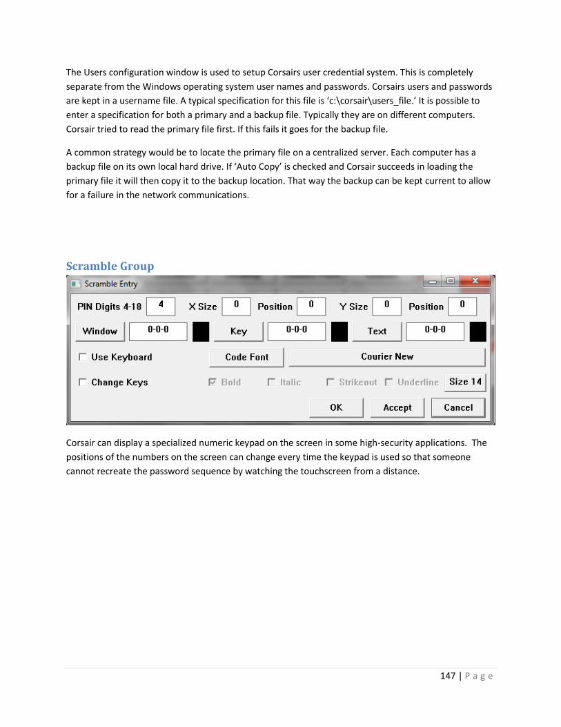
147 | P a g e
The Users configuration window is used to setup Corsairs user credential system. This is completely
separate from the Windows operating system user names and passwords. Corsairs users and passwords
are kept in a username file. A typical specification for this file is ‘c:\corsair\users_file.’ It is possible to
enter a specification for both a primary and a backup file. Typically they are on different computers.
Corsair tried to read the primary file first. If this fails it goes for the backup file.
A common strategy would be to locate the primary file on a centralized server. Each computer has a
backup file on its own local hard drive. If ‘Auto Copy’ is checked and Corsair succeeds in loading the
primary file it will then copy it to the backup location. That way the backup can be kept current to allow
for a failure in the network communications.
Scramble Group
Corsair can display a specialized numeric keypad on the screen in some high-security applications. The
positions of the numbers on the screen can change every time the keypad is used so that someone
cannot recreate the password sequence by watching the touchscreen from a distance.

148 | P a g e
Style Group
The ‘Use Small Windows’ checkbox is used when the Corsair program is running on a small monitor like
a Raspberry Pi touchscreen. Some development functions are shown differently on small monitors.
Status Height is the height in pixels of the status bar on the bottom of a Corsair graphic screen. It
normally uses a text font that comes from the operating system. The Custom Font checkbox permits the
developer to select another font. The Custom Color checkbox permits the developer to select the color
of the status bar.
The template font is the font that is used for text on I/O module templates. The illustration shows a
suggestion.
MBHR Group

149 | P a g e
The ‘Read Security’ and ‘Write Security’ options are for when the computer is operating as an MBHR
host. Write Security defaults to ‘Never Allow’. If it is enabled with ‘Allow All’ the MBHR remote
computer can write data to the host which can then write it to a PLC.
The remaining parameters are for MBHR remote operation. Read Idle Pause determines the time
between requests from the remote. Putting a time of 0.05s here helps to keep from flooding the master
with requests.
The Reply Time Out time is how long the computer allows for the host to reply. A host over the Internet
may need a longer time-out than one on a local computer. 10 seconds works well in many cases.
The Connect time is how long the computer allows for the host to respond when it initially requests a
connection. It should be as long or longer than the Reply Time Out. 20 seconds is a possibility.
Connect retry is the time after a failed connect request before another connect is tried.
The pipeline count can vary from 0 to 16. 0 or 1 are for no pipelining of communications requests.
Excessive pipeline counts can cause performance problems with the Corsair host, especially with Corsair
extended Modbus protocol.
Serial Group
This group is used to assign serial ports for some configuration options. If Corsair is using Streaming
Serial data security either transmit or receive serial ports are specified here. A maximum of 4 ports can
be operated at the same time.
Corsair can operate in a serial MBHR Host mode using the Modbus RTU protocol. It requires one serial
port.
Corsair can act as a ANSI-compatible serial terminal if it is started with a special command line
parameter. This requires a serial port.

150 | P a g e
Help Files Group
Xxx
Xxx

151 | P a g e
Xxx
EDS Group This is a future option that is not active at the present time.

152 | P a g e
Shutdown Group
Windows Corsair can shut the computer down and optionally reboot it automatically. It will run for at
least the specified minimum run time. If no additional conditions are checked it will shut down after
that time. Up to 3 additional conditions can be added as requirements after that time. Windows may
have to run Corsair ‘As an administrator’ for this option to work.
Developer Preferences The ‘Setup’ ’Preferences’ menu option opens the developer preferences entry window.

153 | P a g e
The program can be individually configured to automatically save Models, Developer Preferences, and
Computer Properties when it is closed.
The ‘Record Sort’ options enable a background sortation process for records like tags, alarms, calls, and
register blocks. Some developers may prefer to leave it shut off so that records do not ‘jump around’ as
data is entered. One option is to turn both of these items on, do a complete thinker cycle, and then turn
them both off.
The ‘Highlight Row’ checkbox is used for sheet-style Corsair database development. It causes the
computer to highlight the entire record, not just the current field. The color is adjustable. The
illustration has a suggestion.
Database error checking goes on constantly as a background process. Advice, Alerts, and Warnings can
selectively be ignored if the developer desires.

154 | P a g e
Printing the Manual The Corsair manual is a collection of printouts that are generated by the Corsair program. Each printout
is considered to be a chapter of the manual. The Corsair developer can select what chapters are to be
included when he prints the manual. He can select many options for the manual including whether or
not to include a main index of the chapters, whether to print indexes with the chapters, page numbering
options, and so on.
Manuals are printed for different purposes with different audiences. Engineers need to review the
design of a project as a part of submittal review. The operators that use the Corsair interface are one
audience. The electricians that maintain the control system are another. The PLC programmer has other
needs. The Corsair developer needs other chapters. Usually different versions of the manual are printed
for different people.
Printing the Manual
The manual is printed from the Corsair program’s main window by picking File/Print/Manuals from the
menu. A window appears that allows the developer to select a printer and a number of copies. Clicking
on the ‘Print’ button on this window causes the computer to go on to the ‘Print Manual’ window. This
window allows the selection of manual printing options. Clicking on its ‘Print’ button starts the printing
process.
Engineer’s Review Chapters
Specifying engineers on large projects sometimes require submittal documentation to verify that the
contractor understands the plans and specifications. Some chapters of the Corsair manual can be used
as a portion of the submittal.
The Computer List chapter tells the engineer what interface computers will be provided by the
contractor.
The Alarms and Calls chapters tell the engineer information about the projects scope of work.
The engineer may also be interested in the Listed Drawings and PLC I/O chapters.
The interlock schemes chapter is used with corrections versions of the Corsair program. The engineer
can use it to verify that the Corsair developer has the same understanding of door interlock logic that he
has.
Operators Chapters
The Computer List chapter tells the operators what computers are running the Corsair program.
The Alarms and Calls chapters give a listing of alarms and calls that have been programmed into the
system. The printout can be of all the alarms and calls in the database or only those that are seen on a
particular computer.

155 | P a g e
The Listed Drawings chapter may include information that is of interest to the operators.
Electrician’s Chapters
Electricians are sometimes interested in the TCP addresses chapter. They may be called in when a
Corsair computer cannot communicate to a PLC. One thing that they can do is use the operating system
‘Ping’ utility to verify that the network cable and hardware going to the PLC are working. This chapter
tells the electrician what address to use to ping a PLC on the network
The Computer List chapter gives a list of what computers are on the system using the Corsair database.
In a large installation it may be a help to tell the electricians where the interfaces are.
Listed Drawings can be used to include wiring diagrams and other documentation about a system.
The PLC I/O chapter tells the electrician where PLC inputs and outputs are located and information
about their addresses, module types, and signal ranges.
PLC Programmers Chapters
The PLC programmer is typically interested in the TCP addresses chapter. It documents the IP address of
each PLC on the network that the Corsair program communicates with. The PLC programmer must set
up the address into each piece of equipment using his programming software. The chapter helps to
verify that each IP address on the network is different.
The Driver and PLC Configuration chapter documents how the communications configuration of the
Corsair program is set-up. The PLC programmer may need this information to help configure his
equipment.
The Door Bits chapter is only available with the corrections version of the Corsair program. It is used to
co-ordinate PLC data addresses between the PLC program and the Corsair database.
The interlock schemes chapter is used on corrections projects to aid the PLC programmer with writing
door interlock logic.
The Tree chapter is by far the most important chapter for the PLC programmer. It is the document of the
data interface between him and the Corsair developer. He should keep an updated copy of the tree with
him at all times when writing his PLC program and during start-up.
The CI Device Addressing chapter is used with Corsair computer-indexed device tags. It correlates PLC
addresses with Corsair computers in systems where multiple computers are used. This speeds up the
writing of the PLC program and helps avoid errors in it.
The ASCII table chapter is useful for the PLC programmer in when he needs to do some ASCII work in the
PLC code. The Corsair programs ASCII expert windows are designed to give him more help in these
cases.
Corsair Developers Chapters

156 | P a g e
The Corsair developer is interested in the TCP addresses chapter since it documents the IP address of
each of the Corsair computers on the network. These addresses must be set into the computer through
the Windows control panel network set-up features.
The device use counts chapter can be an aid to the Corsair developer. It shows how many times each
device tag in the database is linked to something else in the database. Normally each device should be
used at least once. This chapter is extremely valuable when a project has multiple PLCs with identical
programs on identical pieces of equipment. The developer can check this chapter to see if the use
counts of the devices on each PLC match. If they do not match there is a development error.
The Alarms and Calls chapters can be used by the developer to check what he is doing against project
specifications.
The Blocks chapter is used to document the calculation blocks that are available for the developer to
use.
The Computer Properties chapter provides documentation as to how the properties on the Corsair
computer are configured. This record shows what the computer is allowed to do, how it is configured for
printing, and other items.
The Driver and PLC Configuration chapter documents how the communications configuration of the
Corsair program is set-up.
The tree chapter can provide a visual way for the developer to check that PLC addresses in the database
are in the correct place.
The password rules chapter helps the developer to understand the relationship between authority
device values and password levels. This can be difficult to understand without the help of the chapter.
The Templates chapter provides information to the Corsair developer about how to use each of the
standard templates that are within the Corsair program. This includes the required point names,
devices, device sizes, and sometimes suggested addresses.
Reference Chapters
Some chapters are for reference purposes. They serve as an addition to other documentation for the
Corsair program.
The Help chapter is used as a quick keystroke reference for the Corsair developer.
The Error Codes chapter is a printout of the error code numbers that are used by the Corsair program. It
is helpful for the developer when he sees an error code number on the screen.
The ASCII Table chapter prints out a detailed chart of the ASCII codes ranging from 0 to 127.
The Templates chapter tells how the Corsair program uses its standard data templates.

157 | P a g e
The My IP System
All versions of CorsairHMI contain a built-in system for the Corsair computer to determine its address on
the Internet. This is generally not the same as any of the IP addresses of the computers Ethernet ports.
The system is not needed for installations that have a fixed known IP address. It may be important
when a fixed IP is too expensive, when it is not available, or for temporary installations.
Corsair must access a web service that provides reporting of IP addresses. The developer must
determine what URL address he is going to use for a service. Two possibilities are:
checkip.amazonaws.com
whatismyip.akamai.com

158 | P a g e
These and other URLs can be verified for proper My IP operation using the TCP Expert’s My IP Expert.
When proper operation of a URL has been verified with this window it must be entered into the My IP
group on computer configuration.
The Hours entry is set to a nonzero value to activate the automatic My IP system. The first check will be
5 minutes after the CorsairHMI program is started. Additional checks will occur at intervals of the
number of hours that is entered here. The service’s URL is entered into the edit box on the right.
The Send Group number is the key number for an email send group for IP address notifications. It must
be nonzero for messages to be sent. The normal action is to send one message when the address is
checked the first time. After that the address is rechecked at the IP Hours interval but messages are not
sent unless it changes. The ‘Always’ check box is used to make Corsair send messages with every check
of the IP address. If the hours are set to 24 and Always is checked Corsair will send an IP address
notification at daily intervals.
The next step may be to embed the My IP address in alarm email messages. This is done from the
computer properties email tab.

159 | P a g e
The option to ‘Include URL in Email’ must be checked. Normally Corsair uses the URL that is entered
into the edit box. If ‘Embed IP’ is also checked it will put its current My IP into each email. It will send
‘http://’ followed by the IP followed by whatever is entered into the edit box. This may be something
like ‘:83’ if Corsair is acting as a web host on nonstandard port 83.
If the following things are true:
Corsair is configured to act as a web host.
The My IP system is properly configured.
The local router is properly set up with port forwarding.
The Internet Service Provider is cooperative.
then when Corsair sends an alarm message by texting to a cell phone the cell phone user can click on the
URL in the message to open his browser and view Corsair.
The Help/About window has a button to open the My IP system monitor window.

160 | P a g e
This window shows a summary of what is happening with the automatic My IP system. The Go button
can be used to start a read of the IP. The Email button provides a review of the IP Address reporting
email message.
New Versions via Email CorsairHMI may wish to email a new version of the corsair.exe program to a customer. Many email
systems will not permit receiving a .exe executable program. The customary way to handle this is to
email the program disguised as a Microsoft Word document. The file name that is used is ‘Mike.doc’.
When you receive this file do not open it. It must be renamed to ‘corsair32w.exe’. The operating
system may issue a warning about changing the extension of a file name. This warning can be ignored.
Using CorsairHMI with Linux Versions of the CorsairHMI software can be purchased for use with computers that are running the
Linux operating system.

161 | P a g e
CorsairHMI System Design
Integration work with the CorsairHMI program involves more than development of the interface
graphics. It includes
Defining the communications architecture
Selecting network hardware
Determining Corsair license requirements
Selecting other required software
Coordinating the efforts of the developer and the PLC programmer
Defining network addresses
Determining what hardware and software tools are needed to configure equipment
Getting Register Maps for connected equipment
Collecting email requirements and addresses
This manual contains information that is required for these and other tasks.
PLC Addressing A tag that is located on a data source requires some sort of address to tell where the data is found on
the source. Frequently this source is a PLC – a Programmable Logic Controller. The PLC manufacturer
defines what sort of addresses it uses.
Corsair Address Builder windows are windows that are defined for each driver. They assist the
developer with entering addresses that are correct for that driver. The developer presses the F2 key to
begin entry of the address, then F1 to open the address builder.
A memory tag that is not on a data source does not require any entry in the address field.
Register Monitors Operator interface programs like Corsair monitor and control processes through tagged data. A
developer typically sets up the program to communicate with a data source before creating any tags.
Register Monitors are windows that are used with data sources without using tags. They can be used to
investigate the information coming from the data source before the tags are created.
Register Monitors will be different for different types of drivers. Some register monitors are view-only.
Some have control capabilities. Some have features to simplify the tag creation process. All register
monitors can only be viewed while the interface is running and only if the data source is ‘Live’.

162 | P a g e
Modbus Family Addressing Drivers that are based upon some version of the Modbus protocol have 4 different types of data
addresses. Addresses that begin with the number ‘0’ are memory bits or ‘coils’. Addresses that begin
with ‘1’ are input bits. ‘3’ is the leading character for a 16-bit input register and ‘4’ for a 16-bit holding
register. The prefix data type number is followed by the offset number of the data within that block of
memory. These offsets start at 1. The first holding register is 400001. The second is 400002.
Corsair does not depend on a fixed number of numbers in the address. It only looks at the first digit to
determine the type. ‘40001’, ‘400001’, ‘401’, and ‘41’ all refer to the same register. When Corsair
generates a Modbus address it generally will use the ‘six-digit’ format. It can use more digits for the
specialized addresses with extremely large offsets that are possible with nonstandard protocols.
Corsair’s proprietary extended modbus can use holding register 4998736. Standard modbus systems can
only go to 49999 or 465536.
There is an address builder window for use with these drivers.
Data that is changeable by the Corsair HMI program must be of the 0x or 4x type. 1x and 3x data is not
writable.
All Modbus compatible drivers use a similar register monitor.

163 | P a g e
The monitor data is displayed in a sheet-style format. The first address is entered into the edit control
on the top of the window. The ‘Address’ button can be used to open the Modbus address builder to
assist in entering the address. The ‘Count’ edit control is used to enter how many data items are going
to be read by Corsair. When the ‘Enable’ checkbox is checked Corsair will start reading the data from
the data source and displaying it with a variety of data formats. The status bar on the bottom of the
window will report any errors.
The operator can arrow around the rows and fields of the sheet data or click on a field to select it. For
some fields the operator can enter data that is to be written to the data source. After putting the value
into the ‘Entry’ edit control the ‘Set’,’Entry’ menu option is used to send the data. Some fields permit
the ‘Turn On’ and ‘Turn Off’ menu options.
The ‘Set’,’Create Tag’ menu option is used to create a Corsair tag at the address on the current line. The
type of the tag depends upon which data format is selected. This tag creation option is only available
for certain fields.
The second line of controls on the screen includes an edit box that may show a name of a corsair
database record. It may be a tag, a register block, an alarm, or a call. This is a record that includes the
address that is shown on the selected line. The ‘View’,’Adjust for Tag’ menu option may be used to
change the entered address to match the starting address of the tag.

164 | P a g e
Possible fields for the Modbus Register Monitor include:
Address – the Modbus address of the data for that line
Signed – the value as a signed 16-bit integer ranging from -32768 to +32767
ASCII – the 16-bit value is represented as two ASCII characters
Binary – the value as 16 binary bits, each of which is 1 or 0
Bit 15 to Bit 0 – the binary value of an individual bit of the 16-bit data
Unsigned – the value as an unsigned 16-bit integer ranging from 0 to 65535
Hex Value – the value as a 16-bit integer in hexadecimal
Flagged Int – an unusual signed 16-bit data type. The most-significant bit is used for the sign and the
other 15 bits represent the value. This is not the same thing as normal twos-complement data.
Hex Offset – the Modbus communications offset of the address, expressed in hexadecimal. This can be
used to verify addresses with many manufacturers published register maps.
Both the DINT and Float types are 32-bit data. Each element takes up 2 consecutive 16-bit Modbus
registers. Equipment venders differ in the order of how the data is arranged. Most Corsair Modbus
drivers give the developer separate options to ‘reverse’ the order of the registers for DINTs and Floats.
The DINT and Float fields show the values using the current setting of the reversing options. The
Reversed DINT and Float fields show the values using the opposite settings. The developer is to change
the settings if needed so that he sees the correct data in the DINT and Float fields. After that he can
create DINT and Float tags on the data source.
Allen-Bradley DF1 Family Addressing There are some drivers that use addresses compatible with the Allen-Bradley DF1 protocol. These
addresses begin with a data file type designation. It can be B for a binary data, F for floating point, N for
integer, ST for string, and L for double (32-bit) integers. The next part is a file number, followed by a
colon, and then the array element number within the file. The B and N data types can have an optional
bit number ranging from 0 to 15.
There is an address builder window for use with these drivers.

165 | P a g e
The Allen-Bradley register monitor is very similar to the Modbus monitor described in the previous
section. It has less fields because the formats for AB data are more strictly defined than they are for
Modbus.
Reserved Addresses Some drivers must connect to devices that do not have defined addressing. In these cases Corsair uses
special addresses that it has reserved for different types of data. The About printout for the driver
contains a list of these reserved addresses.
Aux Databases Some drivers require additional setup configuration data. They use a system of Auxiliary databases.
Aux database data is shown in a sheet-style row and column format. The developer enters this data and
then saves it into the Model file with the ‘File’ ‘Save File’ menu option. It is important to note that he
will not be warned if he closes the Corsair program without saving this data.
The About printout for a driver contains a list of what aux databases are used by the driver.

166 | P a g e
Driver Types Each driver record in the CorsairHMI database has the ‘??’ undefined type when it is initially created.
The developer must determine what type to use for the record. Press F2 to edit the type field and then
F1 to open the type selector.
ABCLX – Allen-Bradley Logix Xx
ActiveX – ActiveX Control Interface The ActiveX driver can be used to interact with some types of ActiveX Controls that come from
companies. This driver cannot be used with Linux versions of the Corsair program.
ANSITERM – ANSI Terminal Text Display The ANSITERM driver is used to drive a standard VT-100 compatible text terminal from a serial port. The
terminal is a display-only device. The computer ignores any keystrokes that come from the terminal.
The connecting wire that transmits data from the terminal to the Corsair computer can be left
unhooked. This makes it impossible to ‘hack’ into the computer system from the text terminal. The
system is similar to what Corsair does with streaming serial data security. Because of that it may be
usable in some corrections systems where text display is desired in an area accessible to inmates.
With proper RS-422 or RS-485 connections multiple terminals can be multi-dropped on the same serial
line. These terminals are not addressable so each one will display the same thing as all the others.
ASCII Read – Unsolicited – Serial Port Background
The Corsair ASCII Read driver is designed so that the Corsair program can accept unsolicited ASCII data
from an instrument over a serial communications line. The term ‘unsolicited’ means that the Corsair
program does not initiate communication by sending data requests to the instrument. Usually the
instrument only transmits and does not receive. Corsair usually only receives and does not transmit. The
serial line may be RS- 232, RS-422, or RS-485. It is generally not possible to multi-drop several
instruments on the serial line with this driver.
A bar code scanner is an example of an instrument that may send data to Corsair using this driver. It
would only send data when a bar code is scanned. Another possibility would be a temperature
monitoring instrument that sends the temperature value at a regular timed interval. In each case the
data that is send by the instrument must be in a format that the driver can accept. The driver has been
designed to accept a wide variety of input data but it cannot be guaranteed to accept any data stream.

167 | P a g e
Applications that use this driver should test it using a free demonstration version of Corsair before a
license is purchased.
The driver is typically used only with ASCII data with character values ranging from 1 through 128. It
cannot be used with raw binary data. Received data packets must be marked by one or more definite
trailing delimiter characters. Packets that are only marked by a leading character may not be usable with
this driver.
To be discussed – fixed character count after header with no trailer???
The Driver Record
The developer must first create a driver record in the Corsair database. After creating the record he can
press F6 to jump to single-record editing of the driver record. This window has an ‘About’ button that
will print a document explaining the options that are available with the driver. It is highly recommended
that the developer print this out to see what options his version of Corsair will support. It is also
recommended that the developer prints out the ASCII character table that is available as part of his
Corsair application manual. This lists all the available ASCII characters with their decimal equivalents.
The developer must specify a serial port number as a part of the driver database record. This number
can range from 1 to 10. It must be a serial port that is not in use by another driver. The developer must
enter the transmission properties of the port. These include baud rate, stop bits, and parity. The
developer must create one or more PLC records under the driver. When the program starts interface
operation the driver will send incoming serial line characters to each of the PLC records. Most systems
will use only one PLC record with each ASCII Read driver although an unlimited number is possible.
Driver Transmit Options
The driver can be set up to periodically transmit up to 3 fixed data packets to the remote instrument.
These packets can only be changed by the Corsair developer. They cannot change dynamically as Corsair
is running. These are not true ‘polling’ packets as Corsair does not wait for a response after sending
them. Packets are sent at regular timed intervals whether the remote instrument replies or not. The
developer specifies the transmit data packets in 3 parts. The first part is 0 to 3 leading characters that
the developer specifies as raw ASCII values. The second part is three different character strings that the
developer types in. The third part is 0 to 3 trailing characters. They are also specified as raw ASCII values.
This approach allows the developer to specify non-printable control characters like carriage returns or
line feeds in the lead or trail part of the packet. The developer also enters the time interval for
retransmitting the packet. If this interval is set to zero Corsair will not do the transmission.
Received Packet Format Discovery
In most cases the Corsair developer should know the format of the data that is coming into the serial
port. This is essential for him to set up the Received ASCII Processing. If he does not know the format he
may be able to reverse-engineer it with the help of the Corsair Comms Trace window. This window is
accessed as Tools/Expert/ASCII Expert/Comms Trace. The driver must be set up and the interface turned

168 | P a g e
on before this window will show the incoming character stream. The separation of the incoming receive
characters into groups by the Comms Trace window is not significant. The developer can accumulate
several characters in the Comms Trace. He can then pause it and print the contents of the trace buffer.
The printout can then be used to determine the trailing packet termination character or characters, if
the packet has leading header characters, and other information. The rest of the reverse-engineering
can probably be done with the PLC Register Monitoring window.
Received ASCII Processing
Corsair can perform several operations on the received data before it is ready to assign to a tag. These
operations are divided into levels. The processing is competed on each level before Corsair starts the
processing on the next level. There are a total of 9 levels. Corsair can perform more than one type of
processing at most of the levels.
The type of processing is specified as driver-specific setup data items on both the driver and PLC
records. This can be done by zooming on the records or by buttons on the PLC Register Monitoring
window.
The PLC Register Monitoring Window
The PLC Register monitoring window is used with most drivers to monitor and change values in PLC
registers. This menu option creates a different window when the PLC is attached to an ASCII read driver.
The window is a dynamic display of incoming serial port data showing the different levels of receive
processing. Each level shows a check box on the left side of the window. There may be an error code
number showing on a button on the bottom of the window. The developer’s intention is to get all of the
boxes checked and no error on the button. When this is complete he can create tags under the PLC
using reserved addresses that are specific to the ASCII Read driver.
The strings that are shown on the PLC Register Monitoring Window are modified to make non-printing
characters viewable. This is done with slash sequences that are marked with the back-slash ‘\’ character.
A space is shown as \SP\. Control characters are shown with their ASCII names. Carriage return is \CR\.
Line feed is \LF\. Characters with values over 127 are shown as a decimal number between the slash
marks. A literal backslash is shown as two consecutive backslashes. Typically the developer applies the
parsing rules in several levels until he sees a result that is free of backslashes. That result is the data that
is applied to a tag.
The PLC Register Monitoring Window may not be able to show the entire packet from each level since it
is limited in the number of characters that it can show.
Driver Level 1 Received Character Processing
Level 1 processing is done at the driver level before the characters are passed to each of the PLCs.
Corsair has no concept of separate data packets at this level – it just sees a stream of characters. The
same processing that is done by the driver is done on the data going to each of the PLC records. The
Level 1 data that is shown on the top of the PLC Register Monitoring window is the result after Level 1

169 | P a g e
Driver processing. The only way that the developer can see data before this processing is applied is by
using the Comms Trace.
Since the Driver has no knowledge of packet boundaries at level 1 there is only a limited amount of
simple processing that it can do. This includes character replacement, skipping characters, high bit
processing, and case correction. They are defined using Driver setup items. The processing is always
done in the same order that the setup items are shown on the developer’s window or listed on the
‘About’ printout.
The first thing that the driver can do is a series of character substitutions. The developer enters a
replaced character and a corresponding replacement. These entered characters can have values as high
as 255 and can include the 0 NULL character. If a replaced character is entered as 46 and the
replacement is 44 all periods are replaced with commas.
The next thing that a driver can do is skipping different types of characters. The developer enters a
character value ranging from 1 to 255. It is not possible to skip zero Null characters with this type of
processing. If the developer enters a value of 65 the driver will eliminate all characters whose value is an
Upper-Case ‘A’.
The next thing that the driver can do concerns characters whose high-order bits are on. These
characters would have values ranging from 128 through 255. The drive can take no action and pass the
characters through unchanged. It can shut the high bit off which effective subtracts 128 from the
character value. It can skip all characters whose high bit is on.
An incoming data stream may have some high-bit-on characters that are needed for defining packets
and some that are to be ignored. One approach may be to change the desired characters to a seldom
used character like the 126 ‘tilde’. This changes them to a high-bit-off character. Then the remaining
high-bit-on characters can be skipped.
The next driver action is to strip out ASCII Null (zero) characters. Corsair does this by default but he
developer can set the driver to pass Nulls.
The next driver action is to skip all Space (decimal 32) characters. This has the same effect as the earlier
Skip actions except that it is limited to a fixed character value of 32.
The next driver action is to deal with received carriage returns and line feeds. Both can be left in, the
driver can skip either one, or the drive can skip both.
The next driver action concerns control characters with values less than 32. The driver can pass them
through, it can skip all of them, or it can skip all of them while still passing carriage returns and line
feeds.
The next drive action concerns the case of letters from ‘A’ to ‘Z’. They can be left as they are, changed to
upper-case, or changed to lower-case.

170 | P a g e
After the developer sees what he wants in the Level 1 Register Monitoring Window he needs to define
how the incoming data stream is to be divided into packets.
PLC Level 2 Packet Definition
Packet definition is to be done at the PLC level. An ASCII Read driver may feed data to
multiple PLC records. Each PLC record can use different definitions for a packet. Data packets are always
defined with at least 1 trailing character. As an option they may also have 1 or more leading characters.
Frequently there is only a single trailing character which is as ASCII carriage return (decimal 13). This
character shows as \CR\ in the level 1 Register Monitoring Window. In this case characters are read in
until a carriage return is encountered. The return marks the end of the packet. Corsair copies the data
from the Level 1 to the Level 2 buffer and then takes the data out of Level 1.
The developer can specify from 1 to 3 trailing characters. If more than one is specified they must arrive
in exact order in order to be considered as a valid packet end. Packets can also be defined with 0 to 3
lead characters in addition to the minimum of 1 trail characters.
It is important to note that the specified leading and trailing characters are required to define the
boundaries of a packet but they are not a part of the Level 2 packet. The packet that Corsair works with
is after the last lead character and before the first trail character.
The developer can specify a Level 2 Post-Trailer skip count. This is a fixed number of characters that are
skipped after the packet trailer. It can be used in unusual situations where a checksum appears after the
trailer.
PLC Level 6 Field Parsing
The Corsair driver works on the data stream with level 1. The PLC rules modify the data stream with
levels 2 through 5. Each of these levels results in a single string with a length that is shown on the
Register Monitoring Window. Level 6 offers the ability to split the Level 5 data into up to 10 fields. This is
done with different types of field parsing.
The simplest field parsing is to pass the level 5 string to level 6 as one field. A common type of filed
parsing is to use commas as a separator. Corsair will divide the Level 5 packet into fields based upon the
positions of the comma character. Commas will not appear in the resulting fields. A space character can
also be used as a field parsing delimiter. If a comma or a space cannot be used to separate fields a
custom parsing delimiter character can be entered. The ASCII Null (zero) character can be used as a
custom parsing delimiter.
The Register Monitoring Window shows how many fields are present at Level 6. The developer can enter
a minimum number of Level 6 fields ranging from 0 through 10. If the data does not produce the
minimum number of fields the packet is rejected.
PLC Level 3-5 and 7-9 String Parsing

171 | P a g e
The developer can enter up to 12 string parsing actions. Each of these actions is specified with 4
parameters.
The first parameter is the parsing action. If it is set to ‘Do Nothing’ no further action is done. There are
several available string parsing actions. Different actions use different combinations of the second
through fourth parameters.
The Second parameter is the Parse Character. It is may range in value from 0 to 255.
The third parameter is the Second Character. It also ranges from 0 to 255. Some parse actions may view
this parameter as a number or count and not as a character.
The fourth parameter is the Label. It is a text field that may be up to 6 characters long.
Six string parsing actions apply before the data is separated into fields at Level 6. These actions are
called Level 3A, Level 3B, Level 4A, Level 4B, Level 5A, and Level 5B. The Level 4 data that is shown on
the Register Monitoring Window is the result when the Level 3B data is modified first by the Level 4A
action and then by the Level 4B action.
Six more string parsing actions are applied after Level 6. These actions are called Level 7A, Level 7B,
Level 8A, Level 8B, Level 9A, and Level 9B. Each action is applied to each of the fields at that level. The
Level 8A type is applied to all of the Level 7B fields before the Level 8B action starts.
Minimum Result String Length
The developer specifies a minimum result length with the PLC record. A packet may show as valid with
all levels checked on the Register Monitoring Window and still not meet the requirement for a Minimum
Result Length. This Length is taken into account when passing data from the packet to a Corsair Tag.
PLC Reserved Tag Addresses
Corsair tags created under PLCs with the ASCII Read driver can have anything for a TAG ID name but
they can only have certain pre-defined addresses. The driver type ‘About’ printout lists all the available
reserved tag addresses. Most of the addresses show a specific Level and some show a field number.
The address “Level5” means that the tag gets its data from the results after Corsair has done all the
parsing up to and including the Level 5 actions. If the data has less than the minimum result string length
in level 5 the data is rejected. The address “Field910” means that the tag gets it data from the results
after Corsair has done all the parsing up to and including the Level 9 actions. The data comes from the
number 10 field.
The “Timed Out” address is for an indicator. The PLC turns this tag on when a valid packet has not been
received for a time longer than the PLC timeout value. The tag is turned off when a valid packet has
been received.

172 | P a g e
The “Complete” address is for a special indicator. The PLC turns this tag on when an acceptable packet
has been received. It does not turn the tag off. The tag can then be used in other parts of the Corsair
program to perform functions like tripping a data log. The data log should then turn the tag off.
Match Characters and Fields
Systems that are set up with multiple PLCs using this driver typically are set up so that each PLC rejects
packets that are not meant for it. This is done through ‘Match Characters’ or ‘Match Fields’. A Match
Character is a character at a predefined position in the input stream. If a PLC looks for a Match Character
at a position and that character is not found the packet is rejected. A Match Field is specified with a label
and a field number ranging from 1 to 10. If the contents of the field do not begin with the Label the
packet is rejected.
Frequently Match Field Checks are applied at Level 8. Level 9 processing removes labels so that the
desired value appears as a Level 9 field. For example, at Level 8 Field 3 might show “TEMP=53.6”. A
match field check might look for the label “TEMP=”. If it does not match the packet is rejected. A Level
9A parsing action would move ahead to a Numeric Character. This would leave “53.6” as data for a Level
9 Tag. Another PLC record may be match checking for “HUMIDITY=”. Since parsing labels are limited to 6
characters it could check for “HUMIDI”.
PLC String Parsing Action Reference
The term ‘Numeric’ refers to the digits 0 through 9, the minus sign, and the period (point). A comma or a
plus sign are not considered to be a numeric by Corsair.
The term ‘Alpha’ refers to letters. It includes upper case ‘A’ (65) through ‘Z’ (90) and lower case ‘a’ (97)
through ‘z’ (122).
‘Alpha-Numeric’ characters are characters that are either Numeric or Alpha. A ‘Control’ character is a character with an ASCII code value less than 32. A ‘Space’ has an ASCII value of 32. A ‘Comma’ has an ASCII value of 44. A ‘Carriage Return’ (CR) has an ASCIII value of 13. A ‘Line Feed’ (LF) has an ASCII value of 10. A ‘Mixed Case’ string begins with a capital (upper case) letter with the rest of the letters in lower case.
The term ‘Skip’ means eliminate a character from the string.
The term ‘Move Ahead To’ means eliminate all the characters before an item but leave the item.
The term ‘Move Ahead Past’ means eliminate all the characters before an item and also eliminate the
item itself.
‘High Bit’ characters are characters whose most-significant bit is turned on. They have ASCII values
ranging from 128 to 255.

173 | P a g e
The term ‘Compress’ means to change two or more consecutive occurrences of a character to a single
occurrence.
PLC String Parsing Action Categories
The many different parsing actions can be divided into several broad categories.
One category is character modification actions. They may change a character but they do not change the
length of a string.
Force upper case – Limit to Non-Zero Maximum Count Force Lower case – Limit to Non-Zero Maximum Count Force Mixed case – Limit to Non-Zero Maximum Count Force upper case on parse character – Limit to Non-Zero Maximum Count Force lower case on parse character – Limit to Non-Zero Maximum Count Force upper case on characters - counted from start Force upper case on characters - counted from end Force lower case on characters - counted from start Force lower case on characters - counted from end Mask all high bits off – Limit to Non-Zero Maximum Count Another category is Skip Actions. A skip action takes one or more portions of the stringand eliminates
(skips) characters. The skip actions include:
Skip spaces between +- and a number
Skip All Control Characters except parse character Skip all non-printable except parse character Skip Leading non-printable except parse character Skip Trailing non-printable except parse character Skip All Occurrences of Parse Character Skip Leading Group of Parse Character Skip Trailing Group of Parse Character Skip Occurrences of Parse Character - counted from start Skip Occurrences of Parse Character - counted from end Skip All Occurrences of Label Skip Occurrences of Label – counted from start Skip Occurrences of Label – counted from end Skip all non-numeric except parse character Skip all non-hex except parse character Skip all non-alpha except parse character Skip all non-alphanumeric except parse character Skip all Upper-Case except parse character Skip all Lower-Case except parse character Skip all high-bit characters except parse character

174 | P a g e
Compress all groups of Parse Character Compress groups of Parse Character – counted from start Compress groups of Parse Character – counted from end Another category is Replace actions. One or more portions of the string are replaced with one of the
characters.
Replace all of the parsing character with the second character
Replace all occurrences of the label with the parsing character Replace occurrences of the label with the parse character - counted from start Replace occurrences of the label with the parse character – counted from end Replace all high-bit characters with parse character
Another category is Move Ahead To actions. Each of these actions has a marker. The computer skips all
characters before the marker but leaves the marker.
Move Ahead To Occurrence of Parse Character – numbered from start Move Ahead To Occurrence of Parse Character – numbered from end Move Ahead To Group of Parse Character – numbered from start
Move Ahead To Upper Case – numbered from start Move Ahead To Upper Case – numbered from end Move Ahead To Lower Case – numbered from start Move Ahead To Lower Case – numbered from end Move Ahead to Occurrence of Label – numbered from start Move Ahead to Occurrence of Label – numbered from end Move Ahead To Numeric Group – numbered from start Move Ahead to Hex Group – numbered from start Move Ahead To Alpha Group – numbered from start Move Ahead To Alpha-Numeric Group – numbered from start Move Ahead to High-Bit Character – counted from start Another category is Move Ahead Through actions. Each of these actions has a marker. The computer
skips all characters up to and including the marker.
Move Ahead Through Leading Characters – counted from start Move Ahead Through Occurrence of Parse Character – numbered from start Move Ahead Through Occurrence of Parse Character – numbered from end Move Ahead Through Group of Parse Character – numbered from start Move Ahead Past Upper Case – numbered from start Move Ahead Past Upper Case – numbered from end

175 | P a g e
Move Ahead Past Lower Case – numbered from start Move Ahead Past Lower Case – numbered from end
Move Ahead Past Occurrence of Label – numbered from start Move Ahead Past Occurrence of Label – numbered from end Move Ahead Past Numeric Group – numbered from start Move Ahead Past Hex Group – numbered from start Move Ahead Past Alpha Group – numbered from start Move Ahead Past Alpha-Numeric Group – numbered from start Move Ahead Past High-Bit Character – counted from start Another category is Truncate actions.
Truncate to a maximum number of characters Truncate trailing non-numeric Truncate trailing numeric Truncate trailing alpha Truncate trailing alpha-numeric Truncate trailing high-bit characters Truncate trailing non-printable Truncate trailing group of parse character Truncate trailing characters – counted from end
Another category is the Truncate From actions. Each of these actions has a marker. The computer
truncates the marker and all characters after it.
Truncate from first non-numeric after numeric Truncate from first non-printable Truncate a maximum count of trailing hex characters Truncate from occurrence of Parse Character – numbered from start Truncate from occurrence of Parse Character - numbered from the end Truncate from group of Parse Character – numbered from start Truncate from group of Parse Character - numbered from the end
Truncate from occurrence of Label - numbered from start Truncate from occurrence of Label - numbered from the end Another category is the Truncate After actions. Each of these actions has a marker. The computer leaves
the marker but truncates all characters after it.
Truncate after last numeric Truncate after last alpha

176 | P a g e
Truncate after occurrence of Parse Character – numbered from start Truncate after occurrence of Parse Character - numbered from end Truncate after occurrence of Label - numbered from start Truncate after occurrence of Label - numbered from end
Another category is the verify actions
Verify Parse Character in position - numbered from start Verify Parse Character in position - numbered from end Verify Parse Character in any position
Verify Label in Position numbered from start Verify Label in Position numbered from end Verify Label in any position Verify Label at Start of Numbered Field Verify Label at End of Numbered Field Verify Label in any position of Numbered Field Verify a minimum number of characters Verify an exact count of characters Verify a maximum number of characters Verify a minimum count of numeric data items Another category is combination actions.
Lead, trail, compress parse character Mixed Case, skip all lower Another category is special actions
Limit maximum field count Delimit from occurrence of Parse Character – numbered from start Delimit from occurrence of Parse Character – numbered from end Delimit between Parse and Second Character PLC String Parsing Action Descriptions
String parsing actions are distinguished by a number and a description.
Action 0: Do Nothing
This action does nothing.
Action 1: Force upper case – Limit to Non-Zero Maximum Count

177 | P a g e
aBcDeF is changed to ABCDEF If the count is zero all lower-case characters are changed. If the count is not-zero Corsair stops after
counting out that many letters. Assume that the count is 3
2a4BcDeF is changed to 2A4BCDeF Action 2: Force Lower case – Limit to Non-Zero Maximum Count
aBcDeF is changed to abcdef Action 3: Force Mixed case – Limit to Non-Zero Maximum Count
sAm/SP/daVE/SP/CHARLIE is changed to Sam/SP/Dave/SP/Charlie Action 4: Force upper case on parse character – Limit to Non-Zero Maximum Count
Action 5: Force lower case on parse character – Limit to Non-Zero Maximum Count
Action 6: Force upper case on characters - counted from start
The count must be at least one or there will be an error. The count is of all characters from the start.
Assume a count of 4
2aBcdEF is changed to 2ABCdEF Action 7: Force upper case on characters - counted from end
Action 8: Force lower case on characters - counted from start
Action 9: Force lower case on characters - counted from end
Action 10: Mask all high bits off – Limit to Non-Zero Maximum Count
Action 11: Skip spaces between +- and a number
Action 12: Skip All Control Characters except parse character
Action 13: Skip all non-printable except parse character

178 | P a g e
Action 14: Skip Leading non-printable except parse character
Action 15: Skip Trailing non-printable except parse character
Action 16: Skip All Occurrences of Parse Character
Assume that the parse character is 32 for an ASCII space
/SP//SP/Temp/SP//SP/53.6/SP//SP/
is changed to
Temp53.6
Action 17: Skip Leading Group of Parse Character
Assume that the parse character is 32 for an ASCII space
/SP//SP/Temp/SP//SP/53.6/SP//SP/ is changed to Temp/SP//SP/53.6/SP//SP/ Action 18: Skip Trailing Group of Parse Character
Assume that the parse character is 32 for an ASCII space
/SP//SP/Temp/SP//SP/53.6/SP//SP/ is changed to /SP//SP/Temp/SP//SP/53.6 Action 19: Skip Occurrences of Parse Character - counted from start
Action 20: Skip Occurrences of Parse Character - counted from end
Action 21: Skip All Occurrences of Label
Action 22: Skip Occurrences of Label – counted from start
Action 23: Skip Occurrences of Label – counted from end
Action 24: Skip all non-numeric except parse character
Action 25: Skip all non-hex except parse character
Action 26: Skip all non-alpha except parse character
Action 27: Skip all non-alphanumeric except parse character
Action 28: Skip all Upper-Case except parse character

179 | P a g e
Action 29: Skip all Lower-Case except parse character
Action 30: Skip all high-bit characters except parse character
Action 31: Compress all groups of Parse Character
Compression eliminates consecutive occurrences of the parse character. Assume that the parse
character is 32 for an ASCII space
/SP//SP/Temp/SP//SP/53.6/SP//SP/ is changed to /SP/Temp/SP/53.6/SP/ Action 32: Compress groups of Parse Character – counted from start
Action 33: Compress groups of Parse Character – counted from end
Action 34: Replace all of the parsing character with the second character
Action 35: Replace all occurrences of the label with the parsing character
Action 36: Replace occurrences of the label with the parse character - counted from start
Action 37: Replace occurrences of the label with the parse character – counted from end
Action 38: Replace all high-bit characters with parse character
Action 39: Move Ahead To Occurrence of Parse Character – numbered from start
Action 40: Move Ahead To Occurrence of Parse Character – numbered from end
Action 41: Move Ahead To Group of Parse Character – numbered from start
Action 42: Move Ahead To Upper Case – numbered from start
Action 43: Move Ahead To Upper Case – numbered from end
Action 44: Move Ahead To Lower Case – numbered from start
Action 45: Move Ahead To Lower Case – numbered from end
Action 46: Move Ahead to Occurrence of Label – numbered from start
Assume that the label is “ABC” The string is “DEFGABCHIJABCKLMABCNOP” If the number is 0 the action returns an error. If the number is 1 the result is “ABCHIJABCKLMABCNOP” If the number is 2 the result is “ABCKLMABCNOP” If the number is 3 the result is “ABCNOP” If the number is greater than 3 the result is “ABCNOP”.

180 | P a g e
Action 47: Move Ahead to Occurrence of Label – numbered from end
Action 49: Move Ahead To Numeric Group – numbered from start
Action 50: Move Ahead to Hex Group – numbered from start
Action 50: Move Ahead To Alpha Group – numbered from start
Action 51: Move Ahead To Alpha-Numeric Group – numbered from start
Action 52: Move Ahead to High-Bit Character – counted from start
Action 53: Move Ahead Through Leading Characters – counted from start
Action 54: Move Ahead Through Occurrence of Parse Character – numbered from start
Action 55: Move Ahead Through Occurrence of Parse Character – numbered from end
Action 56: Move Ahead Through Group of Parse Character – numbered from start
Action 57: Move Ahead Past Upper Case – numbered from start
Action 58: Move Ahead Past Upper Case – numbered from end
Action 59: Move Ahead Past Lower Case – numbered from start
Action 60: Move Ahead Past Lower Case – numbered from end
Action 61: Move Ahead Past Occurrence of Label – numbered from start
Assume that the label is “ABC” The string is “DEFGABCHIJABCKLMABCNOP” If the number is 0 the action returns an error. If the number is 1 the result is “HIJABCKLMABCNOP” If the number is 2 the result is “KLMABCNOP” If the number is 3 the result is “NOP” If the number is greater than 3 the result is “NOP”. Action 62: Move Ahead Past Occurrence of Label – numbered from end
Action 63: Move Ahead Past Numeric Group – numbered from start
Action 64: Move Ahead Past Hex Group – numbered from start
Action 65: Move Ahead Past Alpha Group – numbered from start
Action 66: Move Ahead Past Alpha-Numeric Group – numbered from start
Action 67: Move Ahead Past High-Bit Character – counted from start

181 | P a g e
Action 68: Truncate to a maximum number of characters
Corsair shortens the packet if the length is greater than the count parameter.
Action 69: Truncate trailing non-numeric
Action 70: Truncate trailing numeric
Action 71: Truncate trailing alpha
Action 72: Truncate trailing alpha-numeric
Action 73: Truncate trailing high-bit characters
Action 74: Truncate trailing non-printable
Action 75: Truncate trailing group of parse character
Action 76: Truncate trailing characters – counted from end
Action 77: Truncate from first non-numeric after numeric
Action 78: Truncate from first non-printable
Action 79: Truncate a maximum count of trailing hex characters
Action 80: Truncate from occurrence of Parse Character – numbered from start
Action 81: Truncate from occurrence of Parse Character - numbered from end
Action 82: Truncate from group of Parse Character – numbered from start
Action 83: Truncate from group of Parse Character - numbered from end
Action 84: Truncate from occurrence of Label - numbered from start
Action 85: Truncate from occurrence of Label - numbered from end
Action 86: Truncate after last numeric
Action 87: Truncate after last alpha
Action 88: Truncate after occurrence of Parse Character – numbered from start
Action 89: Truncate after occurrence of Parse Character - numbered from end
Action 90: Truncate after occurrence of Label - numbered from start
Action 91: Truncate after occurrence of Label - numbered from the end

182 | P a g e
Action 92: Verify Parse Character in position - numbered from start
Action 93: Verify Parse Character in position - numbered from end
Action 94: Verify Parse Character in any position
Action 95: Verify Label in Position numbered from start
Action 96: Verify Label in Position numbered from end
Action 97: Verify Label in any position
Action 98: Verify Label at Start of Numbered Field
Action 99: Verify Label at End of Numbered Field
Action 100: Verify Label in any position of Numbered Field
Action 101: Verify a minimum number of characters
Corsair rejects the packet if the length is less that the count parameter.
Action 102: Verify an exact count of characters
Action 103: Verify a maximum number of characters
Action 104: Verify a minimum count of numeric data items
Action 105: Lead, trail, compress parse character
This is a combination of actions 17,18, and 31. It skips leading occurrences of the parse character, then
trailing occurrences of the character, and then it compresses all other groups of the character. Assume
that the parse character is 32 for an ASCII space.
/SP//SP/Temp/SP//SP/53.6/SP//SP/ is changed to Temp/SP/53.6 This is a common action to be used before space-delimited field parsing
Action 106: Mixed Case, skip all lower
sAm42/SP/daVE/SP/CHARLIE58 is changed to S42/SP/D/SP/C58 Action 107: Limit maximum field count
Action 108: Delimit from occurrence of Parse Character – numbered from start

183 | P a g e
Assume that the parse character is an ASCII comma.
AAA,BBB,CCC,DDD, If the number is 0 – there is an error If the number is 1 – The result is AAA If the number is 2 – The result is BBB If the number is 3 – The result is CCC If the number is 4 or greater – The result is DDD Action 109: Delimit from occurrence of Parse Character – numbered from end
Assume that the parse character is an ASCII comma.
AAA,BBB,CCC,DDD, If the number is 0 – there is an error If the number is 1 – The result is DDD If the number is 2 – The result is CCC If the number is 3 – The result is BBB If the number is 4 or greater – The result is AAA Action 110: Delimit between Parse and Second Character
Assume that the parse character is 65 for an upper case ‘A’.
The second character is 66 for an upper case ‘B’.
QZAMONKEYBQ Is changed to MONKEY
ASCII Write – Triggered Output – Serial Port Xx
BACnet – Building Automation and Control BACnet is a protocol that is used for building automation equipment. This includes power meters,
HVAC, and lighting equipment. CorsairHMI talks BACnet/IP over Ethernet. Many field devices use a
multi-drop serial communications standard like BACnet MS/TP. Some sort of BACnet router hardware is
required to make the translation from Ethernet to serial.

184 | P a g e
The IP address of a BACnet device is specified on the driver record and not on the data source records. If
multiple BACnet MS/TP devices are on the same router each one requires a separate data source record.
Network routing information is entered under the data source.
There are several special setup data parameters under the data source record.
If no UDP Port number is entered the value will be zero. In that case Corsair will default to using decimal
47808 which corresponds to hexadecimal OxBACO.
The Use Routing Yes/No option allows Corsair to communicate through BACnet routers. If it is set to
‘Yes’ the destination network number and the destination MAC bytes must be properly set. These bytes
are for routing on the BACnet networks. They are not the 6-byte Ethernet MAC address of the router.
BACnet Doors
Corrections versions of Corsair that have door records in their model database must use objects with the
‘ACD access-door’ object type. The developer will enter the type with an instance number for the start
UDP Port Number
Write Priority 1-16
Use Routing? Yes/No
Destination Network
Destination MAC Length 1-6
MAC Byte
MAC Byte
MAC Byte
MAC Byte
MAC Byte
MAC Byte
1
2
3
4
5
6
Scan Door Status of ACD? Yes/No
Scan Lock Status of ACD? Yes/No
Scan Secure Status of ACD Yes/No
Read Present Value of ACD? Yes/No

185 | P a g e
address of the door. An example would be ‘ACD.47.’ Tag addresses for this driver must specify a BACnet
property but door addresses do not.
BACnet Door Status
Corsair reads door status information from a device using up to four properties. They are ‘door-status’,
‘lock status’, ‘secure status’, and ‘present value.’ The developer uses the data source setup parameters
to tell Corsair which properties are present on the device he is using. If all four status properties are
available, the developer will usually choose to not read the present value of the ACD object to minimize
communications. Present value is a required property of the BACnet object. The status properties are
optional so they may not be available with every system.
With most systems the preferred combination is ‘lock-status’ and ‘secure-status.’
BACnet Door Commands
Corsair writes to the present-value property of the door to operate it. 3 standard BACnet enumerations
of the integer are used – 0 to lock, 1 to unlock, and 2 to pulse-unlock. Corsair uses the proprietary
enumeration of 1024 to stop a slider. Corsair does not use the BACnet standard 3 Extended Pulse Unlock
enumeration of any of its standard F1-F4 door control keystrokes. A developer could program something
to write this value as a separate option.
Keystroke options depend upon the type of the door. They include:
Monitored Door No Keystrokes
Half-Cycle Lock F1 – Unlock BACnet enumeration 1
F2 – Lock BACnet enumeration 0
Full-Cycle Lock F1 – Pulse Unlock BACnet enumeration 2
Slider F1 – Open BACnet enumeration 1
F2 – Close BACnet enumeration 0
F3 – Stop Enumeration 1024
Dual-Cycle Lock F1 – Pulse Unlock BACnet enumeration 2
F2 – Lock BACnet enumeration 0
F4 – Unlock BACnet enumeration 1
Corsair reads door status information from a device using up to three properties. They are ‘door-status,’
‘lock-status,’ and ‘secure-status.’ The developer uses the data source setup parameters to tell Corsair
which properties are present on the device he is using. If all three status properties are available, the

186 | P a g e
developer will usually choose to not read the present value of the ACD object to minimize
communications. Present value is a required property of the object. The status properties are optional
so they may not be available with every system. The following sections explain how the driver handles
BACnet communications for door records.
Operation with no property reads
If none of the 3 status properties are available and the present value is not readable Corsair cannot
make good choices about how to display the door status. This is the least desirable operating mode. One
interface cannot tell when another interface has opened a door. It will leave the Secure and DPSI bits
untouched until the interface is used to operate the door.
Type – Slider
Type – Monitored
Operation – Any
Turn on Secure and DPSI
Type – Half Cycle
Operation – Unlock
Turn off Secure and DPSI
Turn on Hold_Open
Operation – Lock
Turn on Secure and DPSI
Turn off Hold_Open
Type - Full Cycle
Operation – Pulse Unlock
Turn on Secure and DPSI
Turn off Hold_Open
Operation – Lock
Turn on Secure and DPSI
Turn off Hold_Open

187 | P a g e
Operation – Unlock
Turn off Secure, DPSI, and Closing
Turn on Opening
Operation – Lock
Turn on Secure, DPSI, and Closing
Turn off Opening
Operation – Stop
Turn on Secure and DPSI
Turn off Opening and Closing
Type – Dual Cycle
Operation – Pulse Unlock
Turn on Secure and DPSI
Turn off Hold_Open
Operation – Lock
Turn on Secure and DPSI
Turn off Hold_Open
Operation – Unlock
Turn off Secure and DPSI
Turn on Hold_Open
Operation with only reading the present-value property This mode is not ideal, but it may permit the system to function when none of the three status
properties are available. Operation should be tested. It may enable one interface to see when another
interface has opened a door.
Operation with only reading the secure-status property
This mode may work well for larger systems since it only requires one property read. It gives an accurate
display of door secure status but no other information. The values are processed in the same way for all
door types.
Value 0 – Secured – Turn on Secure and DPSI
Value 1 – Unsecure – Turn off Secure and DPSI
Value 2 – Unknown – Turn off Secure

188 | P a g e
Type – Dual Cycle – Always turn off Hold_Open
Type – Monitored
Type – Half Cycle
Type – Full Cycle
Type – Slider
Type – Dual Cycle
Operation with reading the present-value and secured-status properties Type – Monitored
Type – Half Cycle
Type – Full Cycle
Type – Slider
Type – Dual Cycle
Alarms
BACnet devices can trigger alarms on Corsair by Corsair reading in single Boolean bits using a tag whose
type is ‘1-bit alarm’ with a size of one. These alarms require one tag of each alarm. Acknowledge status
is kept within the Corsair interface so acknowledging the alarm on one interface will not acknowledge it
on another.
Type – Half Cycle – Always turn off Hold_Open
Type – Slider – Always turn off Opening and Closing

189 | P a g e
The Corsair BACnet driver has some options using BSV ‘bitstring value’ object type. A bitstring value can
represent an array of Corsair alarms if the BACnet server device is properly programmed. If the
Present_Value property of the object is 10 bits long it can be assigned to a Corsair tag whose type is ‘1-
bit Alarm’ with a size of 10. Zooming on the Alarms field of the tag record allows the developer to enter
10 alarms with indexes 0 through 9. When the BACnet device turns a bit on the corresponding alarm is
tripped. When the BACnet device turns the bit off the alarm may or may not clear on Corsair based upon
the setting of the Latching option and the alarms Acknowledge status.
If Corsair needs to reset the alarm the Present_Value property of the bitstring must be writable. If the
object has an Out_of_Service property it must be set to TRUE. Note that Corsair will always write all of
the bits in the string. It will write the reset bit with a zero. All other bits will be written with their status
as of the last time that Corsair read the Present_Value. Programmers of BACnet devices that use Corsair
like this need to allow for it in a way that does not lose a new alarm when an existing alarm is reset.
Corsair can also manually trip an alarm from the Control window which his accessible from the alarm
summary page.
BACnet specifies an optional Bit_Text property for the bitstring value object. This can be used to store a
description for each alarm bit. Corsair cannot use these strings to form the description of the alarm.
They can be read and possible written as a normal BACnet character string array using a Corsair tag
whose type is ‘String.’
It is possible for Corsair to put alarm acknowledge status into the BACnet device. This is a technique that
is proprietary to Corsair so it may not be compatible with other software. It is only recommended for
situations like specialized BACnet shim software that is specifically written to be compatible with the
Corsair interface. It uses bit in the Bit_Mask property of the bitstring value object to hold acknowledge
status. The tag type is changed to a ‘4-bit alarm.’ It’s address is set to the Present_Value property.
Corsair knows by the type that it is to also scan the Bit_Mask property. If the BVS object has an
Out_of_Service property it must be set to TRUE. When Corsair resets an alarm it writes a zero to the
Present_Value bit. The BACnet device must then also zero the corresponding bit in the Bit_Mask
property.
Centurion – Response Technologies Centurion Elite The Centurion driver is used to communicate with a Response Technologies Centurion Elite Duress
system. This uses a serial connection. This driver is present in all versions of the Corsair program. A
corrections license is not required.
The ‘??’ tag address on a Centurion driver can be used as the parameter C ‘Trigger Switches’ input to a
‘Trigger Alerts’ block. The Active Switches Result of this block can be used it trigger Alerts on other
drivers. This tag should only be used on one instance of the block. The ‘??’ .. addresses perform the
same function. They may be used for other instances of the Trigger Alerts block.
DIGIFORT – Digifort VMS

190 | P a g e
Digifort Quick Start
This procedure allows a developer to complete initial testing of the communication between the
CorsairHMI program and a Digifort VMS server.
Install the Corsair program on your computer
Create a c:\corsair folder on your computer.
Copy the corsair.exe program into it.
Right-click on the program and send it to the desktop as a created shortcut.
The Corsair icon should now show on your desktop.
Right-click on the Corsair icon and pick properties.
Set the icon to ‘run as administrator’. This may be under the ‘Advanced’ options.
Go to the www.corsairhmi.com website.
Under the Public Downloads find the ‘free 4-hour corsair runtime license’
Download the ‘CHMI_Demo4.cky’ license file.
Place the license file in your C:\corsair folder. This license will allow the Corsair interface to run for 4
hours. After that the interface will shut off. It can then be restarted for another 4 hours. There is no
limit to the total runtime with this license in 4-hour segments.
Run the Corsair program.
Click on ‘Users/Change Levels’. Type ‘admin’ into the password.
Select the Developer – Administrator option. Click on OK.
The lower-right status bar should now include ‘Dev: Admin’.
Pick the ‘Setup/Computer Properties’ menu option.
On the Startup Tab pick Development-Administrator.
On the Security Tab enter a base session name of ‘Corsair’.
On the Security Tab check ‘Allow Exit’, ‘Allow Minimize’, and ‘Prevent Running a Second Copy’.
Click on OK to accept the Computer Properties.
Click on the ‘Setup/Save Properties’ menu option.
Initialize an Empty Corsair Model

191 | P a g e
Pick the ‘Setup/Model List’ menu option. Pick ‘Edit/Empty’ to create an empty model.
From the main menu pick ‘File/Save File’ and OK to save the model data.
Determine the IP address of your Digifort Server
Corsair requires a 4-byte IP address for the server. If you are accessing a server over the Internet and
you only have a domain name an address will have to be determined. Pick the ‘Tools/TCP Expert’ menu
option. Click on ‘Get IP from Name’. Type the domain name in the ‘Entered Name’ field. Click on the
‘Get’ button. Write down any discovered 4-part IP address. A 6-part address will not work with Corsair.
If the address is not a static IP it may change at some time based upon the server’s Internet Service
Provider. The address on the Corsair data source will have to be changed whenever this happens.
Permanent installations must have static IPs.
Determine the required Digifort information
You will need the Digifort User name and password that you will use. This information will come from
the administrator of your Digifort server.
You will need to have a Surveillance Client running on a computer. It does not have to be the same
computer that is running the Corsair software. You will need to know the name of the client’s monitor
on the Digifort virtual matrix.
Generate an initial Database
Click on the ‘Edit/Database/Generation’ menu option.
Do not use the ‘Empty’ button. Use the ‘Clear’ button to clear out any generator data.
Click on ‘Sessions’. Click on ‘1’. Enter ‘Corsair’ for the ID of the first session (or computer). OK twice to
get back to the main database generator window. A check should appear next to the Sessions button
showing that it will generate a session.
Click on ‘Screens’. Click on ‘1 Ovr’ to specify an overview screen. Enter ‘Digifort Screen’ for the ID of the
screen. OK twice to get back to the main database generator window. A check should appear next to
the Screens button showing that it will generate a screen.
Click on ‘Drivers’. Click on ‘D1’. Enter ‘Digifort Driver’ for the ID of the driver. Pick ‘DIGIFORT – Digifort
VMS’ for the type. Click on ‘Accept’ and not on OK.
Click on ‘S1’ for Source 1. Enter ‘Digifort Monitor’ for the ID of the data source.
Check the ‘Create Reserved Addresses’ checkbox. Enter the IP address of the Digifort server.
Click on Oks and Close until you get to the main database generator window. A check should now
appear by the ‘Drivers’ button to show that it will generate a driver.

192 | P a g e
Click on the ‘Generate’ key and answer the ‘OK’ prompt to do the generation.
Close the Generation window. Corsair will warn you that you are about to lose unsaved generation
data. Click on OK to go ahead and lose the data.
From the main menu pick ‘File/Save File’ and OK to save the model data.
Additional Special Setup data entry
Pick the ‘Edit/Data/Drivers’ option on the main menu. Arrow up until the ‘Digifort Driver’ cell is
highlighted. Press ‘Z’ to zoom.
Enter the master user name and password. Arrow to the desired selection and press F2 to edit.
Escape from the Special Setup window. Escape from the driver database.
Pick the ‘Edit/Data/Sources’ option on the main menu. Arrow up and to the right until the ‘Node’ field is
highlighted. Press F2 to edit it. Type in a value of ‘1’ and press enter for Node 1.
Arrow left until the ‘Digifort Monitor’ cell is highlighted. Press ‘Z’ to zoom.
Arrow through the fields and press F2 to edit each one. The port number can be left at zero. The
Monitor ID needs to be set to the Surveillance client’s monitor name on the virtual matrix The same
user name and password need to be entered here.
Escape from the Special Setup window. Escape from the Source database.
From the main menu pick ‘File/Save File’ and OK to save the model data.
Use the Register Monitor
Click on the ‘Interface’ checkbox to start run-mode operation.
Click on ‘Tools/Data Source/Registers’ to open the Digifort Monitor window.
Use the ‘Get’ buttons to get cameras, monitors, styles, views, users, and Global Events.
Use the ‘Number’ button to number the cameras with a first value of 1.
If there are Global Events click on the ‘G Events’ button to view them. Use the F2 key to enter nonzero
Corsair numbers on each global event.
From the main menu pick ‘File/Save File’ and OK to save the model data.
The following documentation gives more detail as to how to operate the Monitor window.
Digifort Driver Documentation
The Digifort driver enables the Corsair program to switch IP camera images on a monitor that is acting as
a Digifort surveillance client.

193 | P a g e
An example prison system would have 3 Digifort server computers each recording up to 200 cameras.
These servers are known as East, West, and Central. Their IP addresses on the Corsair network are
1.1.1.1, 1.1.1.2, and 1.1.1.3. The system is designed with no more than 200 cameras per server. Each
camera needs a unique Corsair ID number. The developer has decided to use the numbers 1 through
200 for cameras on the East server, 201 through 400 for cameras on the West server, and 401 through
600 for cameras on the Central server.
Besides the 600 cameras and 3 servers the network includes 6 operator workstations. Each workstation
consists of two computers. One computer is running Digifort’s surveillance client. The other computer
of each pair is running the CorsairHMI program. These 12 computers use IP addresses from 1.1.1.4 to
1.1.1.15. The six workstations are identified by their user. They are known as Bob, Carol, Ted, Alice,
Sally, and Roger.
The Digifort developer must enter 200 cameras into each of the 3 servers. He assigns them 600 unique
names. He sets up user names and passwords for each of the 6 users. He sets up permissions for each
user. Bob, Ted, and Alice can view the east sallyport camera but Carol, Sally, and Roger cannot. Sally is
the only one that can see the booking camera.
The Digifort developer must create a seventh user name and password for a ‘master’ user. This user
must be able to see any camera that can be viewed by any of the six users. The Master user login is
used by the Corsair program to get the list of cameras from each server.
The Corsair developer intends for each of the 6 workstations to be using identical Corsair model files.
The Corsair authority system will be used to determine the capabilities of each computer. He creates 6
session records named Bob through Roger. Each session name must have an index value entered for
use with session-indexed tags. Index numbers from 0 to 5 are entered.
The developer then creates a driver record with the Digifort driver type.
There are no IP addresses on the driver record. Zooming on this record allows him to enter the Master
user name and password.

194 | P a g e
The next step is to create Data Source records under the driver. A data source record can represent a
Digifort server, or a surveillance client monitor, or both. This system with 3 servers and 6 monitors will
require 6 data source records. It could also be done with 9 data sources – 3 that represent servers and 6
that represent monitors.
Each data source is set to be ‘Real’ or ‘Live’. A data source record that represents a server needs the IP
address of that server. A data source that represents a monitor but not a server gets a zero IP address.
Each record has a node value that matches the index of the corresponding session. Other drivers do not
use the node number in this way. When a tag on this driver is ‘Session-indexed’ the index number on
the session record corresponds to the node number on a data source. That data source describes a
monitor on the virtual matrix that is used by that session.
This configuration assumes only 1 Digifort ‘Monitor’ per Surveillance client workstation. If more
monitors are created on the virtual matrix additional data source records will have to be developed.
There will still be only three sources for the servers.
The next step for the developer is to zoom on each data source record.

195 | P a g e
The port number is the port that Corsair will use to connect to the server. If it is left at zero the default
value of 8601 will be used. The name of the monitor must be entered. Monitor names must be unique
throughout the whole virtual matrix system. There cannot be a ‘Monitor 1’ on Bob’s client and also on
Carol’s client. The monitor’s Viewing user name and password are entered here. If a workstation
surveillance client has 2 Digifort monitors they will have different ID names but the same user name and
password.
The Replace options are normally set to ‘No’. This will cause Corsair to use the
‘DoNotReloadSameStyle=TRUE’ and ‘DoNotReplaceSameObj=TRUE’ parameters when loading a screen
style and showing an object. Setting them to ‘Yes’ eliminates these parameters. Consult the Digifort
documentation for information about how they work. These parameters are used on data sources that
are servers. They have no effect on data sources that only represent monitors.
The next step is to load the camera list for each of the 3 server data sources. These are the 3 records
that have nonzero IP addresses. It is done from the Digifort driver’s register monitor window.

196 | P a g e
The Camera ‘Get’ key loads the camera database from the server using the Master User name and
password. This list is opened with the ‘cameras’ button.
The database contains the Corsair number for the camera, a camera name and a description. The type
of the camera record is shown along with a Model designation. Some Master users are allowed to see
an address for the camera.
The type field show which records represent IP cameras. The developer may wish to delete other types
of records by blanking out their fields. The remaining cameras need to be numbered. This can be done
automatically using the register monitor windows ‘number’ button or it can be done manually by

197 | P a g e
entering a nonzero number into each record. Corsair cannot switch to a camera that has a zero number.
The developer may wish to use the database ‘sort’ option when he is done numbering the cameras.
Cameras are only listed under server data sources with nonzero IP addresses. The camera databases
under data sources with zero IPs are not used. Each camera that is listed under a driver must have a
unique nonzero Corsair number. This is enforced by the decision to use the numbers 1 through 200 for
cameras on the East server, 201 through 400 for cameras on the West server, and 401 through 600 for
cameras on the Central server.
The Monitor ‘Get’ key loads the active monitors database from the server using the Master User name
and password. This list is opened with the ‘Monitors’ button.
This database shows the active virtual matrix monitors at the time the ‘Get’ button is pressed. This data
can be constantly changing. The developer must clear and then get the database again to get a current
value. The Active Monitors database is meant as a diagnostic aid for developers.
The developer must be sure to save the Corsair model file anytime changes are made to the cameras
and monitors databases.
The ‘Display’ buttons on the Digifort Monitor are used to test camera switching to different spots on the
monitor.
The ‘Styles’ button is used to view a list of screenstyle numbers. The ‘Get’ button reads style numbers
from a server. Each nonzero number represents a different pattern of monitor spots on a screen. The
‘Set’ button can be used to send an empty style to a monitor.
The ‘Views’ database lists public screen views that are available to all surveillance clients. It does not list
screen views that are limited to a user. Each view has a name and a screen style number. Corsair can
send a view to a monitor if the developer gives it a nonzero Corsair number. Corsair numbers must be
unique across servers. The same number cannot be used for a view on more than one server.
The ‘Users’ database lists user names that have been entered into the Digifort server. The Master and
Viewer user names that are entered under the driver and data source record must match entries from
this list.
The ‘Global Events’ database lists global events that have been configured in the server. These are not
manual events. They are global events that the Master user has the right to access. Each event has a

198 | P a g e
name and a description. Corsair can trigger an event if the developer gives it a nonzero Corsair number.
These numbers must be unique across servers.
The ‘Manual Events’ database lists manual events that have been assigned to cameras in the server.
Each event has a Corsair camera number, a name, and a description. Corsair can trigger the event if the
developer gives it a nonzero Corsair number. These numbers must be unique across servers and not
collide with any of the numbers that have been assigned to global events.
Corsair numbers can be repeated across Cameras, Views, and Events. There can be a number twelve on
each. There cannot be two Cameras that both have the number twelve.
The Event Tigger button is next to a number entry box. The developer can enter a Corsair number that
matches either a Global or Manual event. When the Trigger Button is pressed the event is triggered.
There are several Reserved Tag addresses for use with the Digifort driver. They can be created using the
‘Res Addr’ button when doing single-record editing of the data source record.
Some of the reserved addresses for tags with the Digifort driver are designed to not use session-indexed
(‘SI’) addressing. These tags may be indexed as conventional arrays with a size that is greater than 1.

199 | P a g e
Each index of these tags corresponds to a monitor. If a value is written to index 3 of the tag it applies to
the monitor on the data source with a node number that is set to 3.
Some of the reserved addresses for tags with the Digifort driver are designed to use session-indexed
(‘SI’) addressing. These addresses have a ‘ SI’ suffix. The array size field is left at 1. When a value is
written to one of these tags Corsair looks at the address index value of the computer’s session record. It
finds the data source whose node address matches that value. The value is used for that monitor.
Typically the session-indexed version of the address is what is used for hook codes.
User Login IP Security
The Digifort administrator may want to use User Login IP security to guarantee that users only use the
correct surveillance clients. In our example system there must be two IP addresses entered for each
server – the address of the user’s surveillance client and the address of the user’s Corsair computer.
Surveillance Client Configuration
The Surveillance client will need to have at least one monitor configured for use on the Virtual Matrix.
This monitor gets a name that will be used for the ‘Monitor ID’ entry under the data source record.
There are two check boxes in the Virtual Matrix settings:
Show object origin information
Blink border when an object is loaded on the monitor
Both of these checkboxes should not be checked.
Screen Style Tags
The Digifort system comes with some standard screenstyle layouts. These divide a computer monitor
into a number of sections called ‘Spots’. Spots are numbered starting at one. The Digifort administrator
can create custom screenstyles. Each standard or custom screenstyle has a unique nonzero
identification number. It is shown on the right side of the monitor when the administrator is modifying
the style.
There are two tags that are used to set screenstyles into a monitor. They are ‘Set Screenstyle’ and ‘Set
Screenstyle SI’. Both are double integers. They are written with nonzero screenstyle identification
numbers.
The ‘Set Screenstyle’ address can be an indexed address. If it has a size of 1 the style is applied to the
monitor corresponding to the data source that the tag is on. If the address has a size of more than one
which index is written determines what monitor is used. If a style identification number is written to
index 3 of the tag it applies to the monitor on the data source with a node number that is set to 3.
The ‘Set Screenstyle SI’ address is session-indexed with a size of 1. When a value is written to this tag
Corsair looks at the address index value of the computer’s session record. It finds the data source
whose node address matches that value. The style is sent to that monitor.

200 | P a g e
View Tags
The Digifort system can save public screen views. Corsair can display these screen views on a monitor.
This is done with two tags. They are ‘Set View’ and ‘Set View SI’. Both are integers. They are written
with nonzero Corsair numbers that match entries in the Views database.
The ‘Set View’ address can be an indexed address. If it has a size of 1 the view is applied to the monitor
corresponding to the data source that the tag is on. If the address has a size of more than on which
index is written determines what monitor is used. If a number is written to index 4 of the tag it applies
to the monitor on the data source with a node number that is set to 4.
The ‘Set View SI’ address is session-indexed with a size of 1. When a value is written to this tag Corsair
looks at the address index value of the computer’s session record. It finds the data source whose node
address matches that value. The view is sent to that monitor.
Corsair uses the ?? user name and password to set screen views.
Spot Camera Tags
The ‘Spot # Camera’ tags are integer tags that can be used to control what camera appears in each spot
of a screenstyle. Spot 00 is used for a full-screen view. Spots 01 through 16 are for individual spots on a
screen style (layout). The addresses are available in both normal and SI ‘Session-Indexed’ versions.
Writing these tags with zero has no effect. If Corsair writes the value 6 into an index of the ‘Spot 02
Camera’ tag it will look through each server’s camera database. It will search for a record with a number
of 6 and a name that is not blank. Once it finds a camera it must find a monitor. This is determined
differently for a normal tag versus a session-indexed tag. If it is a normal tag the index number that is
written with the value is used to determine the monitor. If it is session-indexed the addressing index of
the computers base session is used to determine the monitor. If a monitor is available the computer
issues an HTTP ShowObject command to the Digifort server that contains the camera. This command
uses the spot number that is indicated by the tag address.
Corsair uses the View user name and password to set a camera on a spot.
Compound-Indexed Spot Camera Tag
The regular Spot # Camera tags do not allow dynamic indexing across spot numbers. There is a special
address that allows this capability. This ‘Any Spot Camera’ address has unique operating rules. It is
session-indexed with an array size that is greater than 1.
To be continued . . .
Starting and Stopping Recording
Corsair can start and stop recording on individual cameras. This requires some changes in the Recording
Settings on the server. Instead of ‘Continuous Recording’ the ‘Recording by Schedule’ option needs to

201 | P a g e
be selected. The Recording Scheduling button leads to the Scheduling window. The ‘Record by Event’
action is used when Corsair is to start and stop the recording.
The ’Start Camera Recording’ tag address is a double integer that is written with a nonzero camera
number to start recording of that camera. It is not indexed so it has a size of 1.
The ‘End Camera Recording’ tag address is a double integer that is written with a nonzero camera
number to stop recording of that camera. It is not indexed so it has a size of 1.
The ‘Camera Recording Switches’ tag is an array of switches with one index for each camera. When
index 6 is turned on recording starts on camera number 6. When index 12 is turned off recording stops
on camera number 12. The tag should have an array size one higher than the highest camera number.
Corsair uses the Master user name and password to start and stop camera recording.
Camera Privacy
The ‘Set Camera Privacy’ tag address is a double integer that is written with a nonzero camera number
to activate privacy on that camera. It is not indexed so it has a size of 1.
The ‘Reset Camera Privacy’ tag address is a double integer that is written with a nonzero camera
number to release privacy on that camera. It is not indexed so it has a size of 1.
The ‘Camera Privacy Switches’ tag is an array of switches with one index for each camera. When index 6
is turned on privacy is activated on camera number 6. When index 12 is turned off privacy is
deactivated on camera number 12. The tag should have an array size one higher than the highest
camera number.
Corsair uses the Master user name and password to switch camera privacy on and off.
Camera Privacy Groups
Corsair supports the development of privacy groups. A privacy group is a list of cameras whose privacy
can be activated or released from a single tag. Each privacy group gets a nonzero number to identify
the group. Each group can contain a large number of cameras.
The ‘Set Group Privacy’ tag address is an integer that is written with a privacy group number to activate
privacy for the cameras on that group. It is not indexed so it has a size of 1.
The ‘Reset Group Privacy’ tag address is an integer that is written with a privacy group number to
release privacy for the cameras on that group. It is not indexed so it has a size of 1.
The ‘Group Privacy Switches’ tag is an array of switches with one index for each group. When index 6 is
turned on privacy is activated for the cameras of group number 6. When index 12 is turned off privacy is
deactivated for the cameras of group number 12. The tag should have an array size one higher than the
highest privacy group number.

202 | P a g e
Corsair uses the Master user name and password to switch camera privacy groups on and off.
Alerts
Corsair can trigger global or manual events on a Digifort server. One way to do this is by writing a
nonzero Corsair number value to the ‘Trigger Event’ tag. The program first looks at the Global Events
database for a matching number. If it does not find it then it goes to the Manual Events database.
When it finds the number if the Master User has the right the event is triggered.
A common way to trigger Digifort events is using the Corsair ‘Trigger Alerts’ block. The block is
documented in the Corsair Designer manual. The driver includes two addresses that are used as
parameters on the block and a third that it uses for itself.
The ‘Alert Active Switches’ tag is used for the Result parameter of the ‘Trigger Alerts’ block.
The ‘Alert Done Switches’ tag is used for Parameter F of the ‘Trigger Alerts’ block.
The block’s Parameter C gets a memory tag or a tag from another driver.
The developer enters in Corsair numbers for the events associated with each element of these tags. This
is done from the ‘Alerts’ button on the register monitor.
Corsair uses the Master user name and password to trigger Digifort events.
Multiple Camera Switches
Corsair can be used to simultaneously switch camera views on multiple spots of multiple monitors from
a single trigger source. This may be called ‘salvo switching. A database can be set up to describe
thousands of Camera/Monitor/Spot combinations from hundreds of triggers.
To be continued . . .
DXI – Harding Instruments DXI Intercom Corsair can control a Harding MicroComm DXI intercom using an Ethernet connection.
DXL – Harding Instruments DXL Intercom Corsair can control a Harding MicroComm DXL intercom using an Ethernet connection.
Harding DXL Configuration
The Harding programmer must define a Host Port on an Exchange in a DXL system. The Host Port must
be set to be Ethernet and not Serial. It needs an IP address that is compatible with the network that the
Corsair computer is on. The TCP/UDP port number should be left at the default value of 10000 for the
first host port on the Exchange. If there are multiple Exchanges each one gets a unique IP address but

203 | P a g e
each one can use the same port number of 10000. If more than 20 computers talk to a single exchange
more host ports will have to be created. The next host port should get an address of 10001, then 10002,
and so on.
The next step is to define the host port protocol. The protocol to use is ‘ASCII Messages’, not ‘Register
Based Messages’.
The Messages tab of the Harding software has some checkboxes for options for the messages. On
option is for status messages to ‘Use Response Message Format’. It should not be checked. Response
messages should have the ‘Respond to All Host Commands’ option checked. The ‘Use Status Message
Format’ option should be checked. Under Acknowledgments the ‘Wait for Acknowledge Messages’
option should not be checked. These settings are different that the Harding software’s default settings.
The Monitor tab of the Harding software has a ‘Monitor Connection for Faults’ checkbox. It should be
checked. The Timeout should be set for the default 10 seconds.
Corsair Development for the DXL
The Corsair program needs to have the development level set to ‘Admin’ so that development work can
start. A driver record must be created. It gets the ‘DXL - Harding Instruments DXL Intercom’ type. The
ID can be any desired name. The PLC network IP address on the driver must be set to match the DXL
intercom Exchange.
The next step is to zoom on the drivers Data Source (‘PLC’) zoom field to enter one or more data source
records.
Each data source corresponds to a master. Anything can be entered for the ID name. The Node number
of the data source must be used to enter the master’s nonzero dial number. Master dial numbers
greater that 65535 will not work here. The Real flag must be set to ‘Yes’.
Most systems will require session-indexed tagging to be used for some Harding tags. With these
systems it is not necessary to create a separate data source for each master station. Create just one
source and give it the dial number of the first master in the system.
At this point Register Monitoring for the data source may be used to check communications to the
intercom.

204 | P a g e
If no tags have been created the master number on the title bar is the dial number of the master that
the window is controlling. It can be used to originate calls to a station, to another master, or to initiate a
page.
The next step is to create tags on the data source record. Select ‘Edit’ ‘Data’ ‘Sources’ and select the
intercom data source. Pressing F6 opens data source single-record editing. The ‘Res Addr’ button is
used to create tags on the data source with addresses that will work for the driver. The sizes of some of
these tags will have to be adjusted as explained later.
After tags have been created the ‘List’ and ‘Groups’ buttons on the Register Monitor are used to open
the auxiliary databases that are used by the driver. Remember that any changes to an aux database are
saved as part of the .cap Model file. There will be no warning prompt if the developer exists without
saving aux database data.
The developer must define a unique index number for each master station, intercom station, station
group, and paging zone that is used in the system. Master stations get the first index numbers starting
at 1. They correspond to session index values in the Sessions database.
The first database to work with is the master list.

205 | P a g e
The master list corresponds Corsair sessions to master station dial numbers. Any computer that uses
the DXL driver has a base session name. This is the name that is set using the Security tab of the
Computer Properties window. The index of that session in the sessions database must be a nonzero
value. The first column of the master list is the call (dial) number of the master. The second column is
the corresponding Corsair session index number. Both columns must be nonzero for the row to be valid.
A name for the master should be entered. The optional comments are for the architecture printout.
Assume that the sessions database has three records:
Central Control - session index 1
North Control - session index 2
South Control – session index 3
Assume that the master list has three records:
Call #101 - Session Index 1 – Name ‘Central Control Intercom Master’
Call #201 – Session Index 2 – Name ‘North Control Intercom Master’
Call #301 – Session Index 3 – Name ‘South Control Intercom Master’
The Central Control computer will be using the intercom master with dial number 101. The North
Control computer will be using the intercom master with dial number 201. The South Control computer
will be using the intercom master with dial number 301.
The next aux database to work with is the Intercom Station List.
The Call # is the dial number for each station. The Tag Index is a nonzero number that locates the
intercom station in an array of tag data. These tag indexes normally start after the range of values that
is used for the indexes in the Master list. They can be entered into the database in any order. The same
tag index should not be used for more than one intercom station. The same tag index should not be

206 | P a g e
used for both a station and a master. Both the Call # and Index columns must be nonzero for the row to
be valid. A name for the station should be entered. The optional comments are for the architecture
printout.
The ‘Master Names’,’Master Index’, ‘Master Numbers, ‘Master Comment A, and ‘Master Comment B’
arrays should all be sized slightly larger than the maximum count of masters in the system. These tags
are never session-indexed.
The ‘Station Names’, ‘Station Index’, ‘Station Numbers’, ‘Station Comment A’, and ‘Station Comment B’
arrays should all be sized slightly larger than the maximum count of stations in the system. These tags
are never session indexed.
The ‘Enable Switch’, ‘End Call’, and ‘Next’ tags should all be left with a size of 1. Usually session indexing
will be set to ‘Yes’ for these tags. If the interface turns on the button with the ‘Next’ address Corsair
looks to see if the tag is session indexed. If it is not session indexed Corsair uses the dial number that is
stored in as the node address of the data source. If it is session indexed Corsair finds the dial number
for its session in the Master List aux database. In either case, if the dial number is zero the ‘Next’
command is not sent to the DXL.
EIP Devices Xx
EIP ID – ID Readers Xx
Email Command The Email Command driver is used to control the email system from Corsair tag data. Different reserved
tag addresses are used for different parts of the email data tree.
Ewert CAN – CANbus The Ewert driver is designed for CorsairHMI to read data from a CANbus system using the CANdaptor
module from Ewert Energy Systems (www.ewertenergy.com). This adaptor hooks to the Corsair
computer using a USB connection. With the proper driver it emulates a serial port. The first step is to
get the driver from Ewert, install it on the computer, and plug in the adaptor. The operating system will
determine what COM port is used by the adaptor. A possible path to see what selection it has made
from Windows would be Control Panel, System, Device Manager. Most of the time the port will be

207 | P a g e
within the range of COM1 to COM4 although it could be a higher number. It is recommended to always
plug the adaptor into the same USB port on the computer to hope that the serial port number does not
change.
The Setup,Comms Port Properties menu selection is used to specify parameters for serial ports. The
baud rate that is entered here is not the baud rate of the CAN network. A nonzero value must be
entered for all serial ports including USB. 9600 baud, 8 data, no parity, and 1 stop bit is a recommended
setting. Port numbers above 4 may require entry of a port name.
A driver record must be created in the Corsair database for the CANdaptor. Each driver record
corresponds to only one adaptor so multiple records will be needed if there are multiple adaptors. The
proper Port number must be entered into that field of the driver record.
After the driver is created one or more Data Sources need to be created under it. They are made by
zooming on the driver’s Zoom field. Each data source needs a name and it needs its ‘Real’ field set to
‘Yes’.
Zooming on the driver record opens the special setup data for the CANdaptor.
It is here that the Baud rate of the CANbus must be entered. Corsair defaults to 500 K baud but other
standard rates are available. There are places to specify up to 2 masks and 7 filters. For now they
should not be used.
The next step is to hook the equipment to the CANdaptor and run the Corsair interface. The View,
Source Diagnostics menu option can be used to verify that the driver is online and ready and to see if
CAN frame data is arriving at the computer. Each CAN frame shows as a good read on the Source
Diagnostics window.

208 | P a g e
A next step may be to go to the Corsair Comms Trace window to see the data packets that Corsair is
receiving from the CANdaptor. The format of these packets is explained by the Ewert documentation.
One thing to observe is if they begin with the letter ‘T’ or with ‘X’. A ‘T’ packet has an 11-bit standard ID
value. A ‘X’ packet has a 29-bit extended ID value.
The documentation for the CANbus equipment should show if it uses 11 or 29 bit IDs and how it formats
its data packets. If there are multiple pieces of equipment on the bus it must be verified that there are
no duplications in frame IDs.
Filtering is the process of eliminating unneeded CAN frames from the data stream so that only the
desired ones are used. The first possibility for filtering is to do all or some of it in the CANdaptor
module. It supports up to 2 mask values that work in conjunction with up to 7 filter values. Frames that
are filtered out in the module do not have to be processed by Corsair which is a key to reducing the
programs CPU utilization.
The first step in applying CANdaptor filtering is to turn on one or both masks by setting the ‘Use Mask’
option to ‘Yes’. The mask must be set to match an 11-bit standard or 29-bit extended frame ID. The
mask hex value sets what bits of the incoming frame ID are checked by the filter. The mask can be a
maximum of hexadecimal 7FF for an 11-bit ID or hexadecimal 1FFFFFFF for a 29-bit ID. Mask bits that
are set to 1 are checked by the filter. Mask bits that are set to 0 are ignored by the filter. A mask value
of 1 (one) would mean that only the least-significant bit of the id is the only one checked.
After one or both mask values are setup at least one filter value must be set. The ‘Use Filter’ option
must be set to ‘Yes’. It must be connected to the correct mask, either mask 0 or mask 1. The filter
values frame ID must be set to 11 or 29 bit to match the mask. The filter value tells the CANdaptor what
values to accept in the ID. It can be as high as hex 7FF for an 11-bit ID or hex 1FFFFFFF for a 29-bit ID.
If all bits are on(1) in the mask the incoming ID must exactly match the filter value for a frame to be
accepted. If the mask is hex 7FF for an 11-bit system and the filter value is hex 3CB then only frames
with an ID value exactly equal to hex 3CB will be accepted.
A mask value of hex 70 would correspond to a binary value of 01110000. A filter value of hex 50 would
correspond to a binary value of 01010000. Only three bits of the ID of each incoming frame are
checked. The following possibilities exist:
Frame ID Hex Frame ID Binary Status
D3 11010011 Accepted
70 01110000 Rejected
DC 11011100 Accepted
63 01100011 Rejected

209 | P a g e
One mask can be used with as many as 7 different filter values. If any of the mask-value combinations
allow it the packet is accepted. If a mask is hex 7FF for an 11-bit system and filter values of hex 3CB and
3CC are used then frames with ID values equal to hex 3CB or hex 3CC are accepted. Any other incoming
ID will be rejected.
The next level of filtering is done by zooming to special setup data on the data source records. This
filtering is done by the Corsair program so it requires more work by the computer than filtering done by
the CANdaptor.
Each data source can receive 11-bit or 29-bit identifier frames but not both. One data source can be set
for 11 and another for 29.
Filtering of the incoming ID value can be done at the data source level. If this filter is enabled 3
hexidecimal values must be entered – a mask, a minimum, and a maximum. Corsair ANDs the incoming
ID value with the mask. If the result is less than the minimum or greater than the maximum that frame
is rejected on this data source. All three values must be entered in hex without a leading ‘0x’. They can
be as great as 7FF for 11-bit IDs and 1FFFFFFF for 29-bit IDs.
To use the Corsair data source ID filter the ‘Use’ field must be set to ‘Yes’. If the Mask value is set to hex
7FF with an 11-bit ID system the minimum and maximum values are checked against all of the bits of the
incoming ID. If the minimum is hex 12 and the maximum is hex 1FF then IDs outside of that range are
rejected.
If the Filter mask is set to hex 0F (binary 00001111), the minimum is set to 3, and the maximum is set to
5 then the following possibilities exist:
Frame ID Hex Frame ID Binary Status
D3 11010011 Accepted
72 01110010 Rejected
D5 11010101 Accepted

210 | P a g e
66 01100110 Rejected
Corsair tag addresses for the CANdaptor driver consist of a series of one or more instructions. Corsair
requires these instructions to understand what it is to do with the CAN data packet. Each instruction
begins with a 4-letter instruction name. The name is followed by 0, 1, or 2 numeric parameter values.
Parameter values are separated by commas. Instructions are separated by semicolons. A possible
address would be:
BYTM 0,FE; BYTP 3,2
This address consists of two instructions. Instructions are separated by semicolons. No semicolon is
needed at the end of the last one. There can be as many as 16 put together to form a complete address.
The possible instructions are shown under Tools, TCP Expert, Protocol Data, CANbus Instructs.
This address starts with a BYTM instruction. It has two parameters, a decimal 0 and a hexadecimal FE. It
is followed by a BYTP instruction. It also has two parameters, a decimal 3 and a decimal 2.
Spaces may be inserted between parts of the address to improve readability. Instruction names are
always 4 characters. Upper case is preferred but lower case is allowed.
The number and type of parameter values varies with the instruction. Some parameters are signed
integers that can be positive or negative. Negative values are preceded with a minus sign. Positive
values should not have a plus sign. Some parameters are unsigned integers that cannot be negative.
Some parameters are hexadecimal numbers. They use the digits from 0 to 9 and letters from A to F.
The letters can be upper or lower case but upper is preferred.
After a starting address for a tag is entered the developer can zoom to the tag data monitor. The
address that is shown on that window is Corsairs understanding of that address. It should look like what
the developer expects.
Instructions are divided into 3 different categories, ‘Matching’, ‘Positioning’, and ‘Scaling’. They should
be entered in that order. There should be only 1 positioning instruction which is the minimum
requirement for a usable address. There can be multiple matching and scaling instructions. The order
of Matching first, followed by Positioning, and then followed by Scaling should be observed.
Matching instructions are used to determine if a CANbus frame applies to a tag. It specifies a data value
that must be matched for the rest of the instruction to be considered. If the match is not true that
frame is not used for that tag.
Positioning instructions are used to locate data within the CANbus frame. A frame consists of an 11 or
29 bit ID value followed by 0 to 8 bytes of data. The positioning instructions specify where the needed
data starts within the frame, its size, and sometimes its type.
Scaling instructions are used to specify mathematical operations that Corsair is to perform on the data
before it is set into the tag.

211 | P a g e
The BITP ‘Bit Position’ instruction is a Positioning instruction with two parameters. The first is an
unsigned offset to tell where the bit data starts. It can vary from 0 to 3. The second value is an unsigned
bit count. It cannot be 0. It can never be more than 64. The sum of the offset and the count cannot
exceed 64.
The BYTM ‘Byte Match’ instruction is a Matching instruction with two parameters. The first is an
unsigned offset to tell which data byte is to be matched. Since there are up to 8 data bytes in a CANbus
frame the offset parameter can be 0 through 7. The second parameter is a hexadecimal byte value that
the frame must match. It can range from 00 to FF. The decimal equivalents are 0 to 255 but the data
must be entered in hex.
The BYTP ‘Byte Position’ instruction is a Positioning instruction with two parameters. The first is an
unsigned offset to tell where the byte data starts. It can vary from 0 to 7. The second value is an
unsigned byte count. It cannot be zero. It can never be more than 8. The sum of the offset and the
count cannot exceed 8.
GESRTP – General Electric Series 90 TCP/IP The GESRTP driver is used by the Corsair program to communicate with General Electric PLCs over an
Ethernet network.
GPS – NMEA Compatible GPS Serial The GPS driver is used by the Corsair program to communicate with a GPS receiver over a serial port. It
requires the standard NMEA protocol.
The NMEA standard calls for serial transmission at 4800 baud, 8 data bits, no parity bit, and 1 stop bit.
GPS equipment is not required to conform to this. If a system is not working the manufacturer of the
equipment should be consulted for the data format that they use.
InterModel – Inter-Model Data Exchange The Corsair program can operate with as many as 100 data models at one time. The InterModel driver is
used to move data between data models that are running on the same computer. A computer may be
running 3 models that correspond to production facilities at 3 different locations. A fourth model could
be used for production summary data. The InterModel driver would be used to copy data from each
facility to the summary model. Corsair then totalizes this data for display.
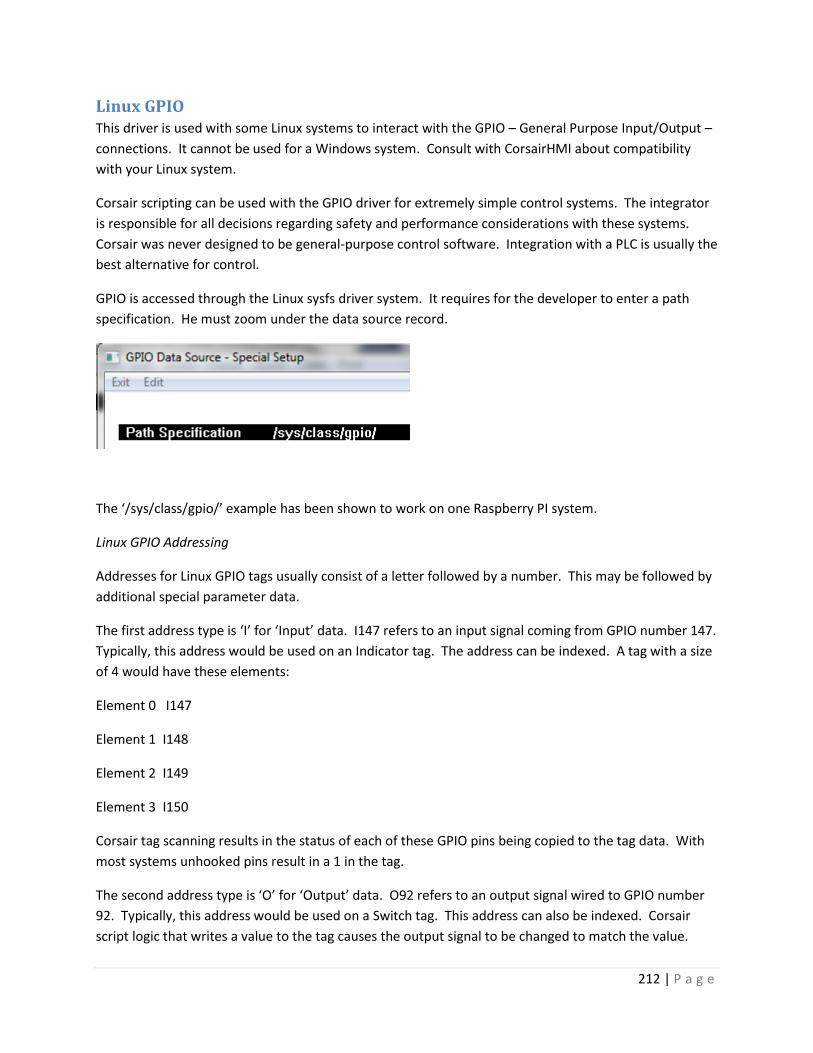
212 | P a g e
Linux GPIO This driver is used with some Linux systems to interact with the GPIO – General Purpose Input/Output –
connections. It cannot be used for a Windows system. Consult with CorsairHMI about compatibility
with your Linux system.
Corsair scripting can be used with the GPIO driver for extremely simple control systems. The integrator
is responsible for all decisions regarding safety and performance considerations with these systems.
Corsair was never designed to be general-purpose control software. Integration with a PLC is usually the
best alternative for control.
GPIO is accessed through the Linux sysfs driver system. It requires for the developer to enter a path
specification. He must zoom under the data source record.
The ‘/sys/class/gpio/’ example has been shown to work on one Raspberry PI system.
Linux GPIO Addressing
Addresses for Linux GPIO tags usually consist of a letter followed by a number. This may be followed by
additional special parameter data.
The first address type is ‘I’ for ‘Input’ data. I147 refers to an input signal coming from GPIO number 147.
Typically, this address would be used on an Indicator tag. The address can be indexed. A tag with a size
of 4 would have these elements:
Element 0 I147
Element 1 I148
Element 2 I149
Element 3 I150
Corsair tag scanning results in the status of each of these GPIO pins being copied to the tag data. With
most systems unhooked pins result in a 1 in the tag.
The second address type is ‘O’ for ‘Output’ data. O92 refers to an output signal wired to GPIO number
92. Typically, this address would be used on a Switch tag. This address can also be indexed. Corsair
script logic that writes a value to the tag causes the output signal to be changed to match the value.

213 | P a g e
The third address type is ‘C’ for ‘Count’ data. These addresses are used for 32-bit Double Integer tags
that count how many times an interrupt has been tripped. Other tag types including Integer are invalid
with C addresses. C addresses cannot be indexed. Tag sizes must be 1. U,6.0 is the recommended data
format. The number following the ‘C’ is a GPIO number.
Count data addresses can be followed by the suffix ‘R’, ‘F’, or ‘B’ for ‘Rising’, ‘Falling’, or ‘Both’. It should
be noted that ‘Both’ operations will result in count numbers that are twice what ‘Rising’ or ‘Falling’
would yield. If no suffix is present Corsair defaults to ‘Rising’.
Each interrupt has a counted value that increments whenever the interrupt is tripped. This is a modulo
100,000 value that resets to 0 for the next count after 99,999. Corsair copies this counted value to the
tag with the ‘C’ address. Counts may be accumulating at a higher rate than the copy to the tag. This
means that the tag will appear to ‘skip’ values as the count increased.
The system can use no more than 10 ‘C’ count tags. Two count tags cannot use the same interrupt
number. There can be a C19 and a C20 but never two C20s.
Corsair includes program blocks that are designed especially for totalization and rate calculations based
upon a modulo 100,000 value.
Considerations for systems that use Interrupts
When a system uses ‘C’ addresses CorsairHMI must set up interrupt processing. The interrupts are
triggered by the status of a GPIO input. The program cannot guarantee correct operation during all
possible program changes on an interrupt system. Tags should not be added or deleted and their
addresses should not be changed with the interface running this driver. Shut off the interface checkbox,
make the changes, and then turn on the checkbox. Failure to heed this may result in crashing the
Corsair program or shutting down the computer.
Linux I2C The Linux I2C driver is currently an input-only driver that is used to read data into Corsair from
integrated circuits connected to a Raspberry PI over the I2C bus.
A few things typically have to be done to the PI to get I2C system to work. This manual is not a
comprehensive reference as to how these things are done on a particular PI. These are some
suggestions that should be investigated. Do not type the single-quotes.
The first thing is to make sure that I2C is not blacklisted in the ‘/etc/modprobe.d/raspi-blacklist.conf’
file. Type ‘sudo nano /etc/modprobe.d/raspi-blacklist.conf’.
If a line like this appears
‘blacklist i2c-bcm2708’
put a hash mark in front of it to change it to

214 | P a g e
‘#blacklist i2c-bcm2708’
and Ctrl-X and Y to save the file.
Next open the ‘/etc/modules’ file by typing
‘sudo nano /etc/modules’
and see if there is a line by itself that says
‘i2c-dev’.
If there isn’t it needs to be added.
An i2c-tools package may need to be added with ‘sudo apt-get install i2c-tools’.
The first step is wiring the device to the PI. Usually a supply plus, a supply minus, an SCL data line, and
an SDA data line are all that is needed. Verify for sure if you want to power the device from a 3.3 or
from a 5 volt connection on the PI.
Determine what I2C address the device should be using. Corsair I2C addresses are always expressed in
hexadecimal with an ‘0x’ prefix. 0x48 is a common I2C address. The device should not conflict with any
addresses that are already in use on the PI. Some devices can use jumpers to switch to different
addresses.
Use the ‘i2cdetect’ tool to see if your device can be seen by the PI. The syntax may be:
‘sudo i2cdetect -y 1’
It is essential that the device is detected at the correct address before any Corsair development is done.
Each I2C device should use a separate driver record. The driver gets the ‘Linux I2C’ type. There is driver-
specific data that must be entered by zooming on the driver record. The first item is the file path and
name. It is typically set to:
‘/dev/i2c-1’
The next two entries are the buss read and write address. This is a 7-bit address expressed as a
hexadecimal number. The same value needs to be entered into both the buss read and write addresses.
This is the same number that was returned by the i2cdetect tool.
Each driver record corresponds to a different chip on the i2c bus. Each data source record corresponds
to a different reading of data coming from the chip. An A to D converter chip may have 4 input
channels. There may be 4 different data sources on the driver record for this chip.
Each data source has a zoom to enter driver-specific data. The first two items are the Bus Write and
Read addresses. They should be set to match the value that was used for the driver record.

215 | P a g e
The next step for the Corsair developer is to enter the sequence of instructions that Corsair needs to
setup the chip and read data from it. Instructions can be entered under the driver record and under the
data source records. The instructions under the driver record are executed one time when Corsair starts
interface operation. They are typically used to configure options on the chip. The instructions under the
data source record are executed each time Corsair wants to read data from the chip. The interval
between executions of these instructions can be set by the ‘Idle Pause’ setting on the Data Source
record.
Both driver and data source records offer the same 5 instruction options:
??
Read Bytes
Write Byte
Finish Write
Delay
These instructions are entered in ‘Command-Value’ pairs. The values can be entered in decimal or in
hex if the developer types the ‘0x’ prefix.
Corsair starts execution at the first command of the list and always finishes the list in a single pass. The
end of the list is found at the first ‘??’ undefined instruction.
The ‘Read Bytes’ instruction tells Corsair to read a number of bytes of data from the I2C bus. The value
is the desired number of bytes. ‘Read Bytes’ instructions can be entered under driver records but there
is no way for Corsair to use these bytes. A ‘Read Bytes’ instruction is frequently the last instruction of
the sequence under a data source record.
The ‘Write Byte’ instruction tells Corsair to write a byte of data to the bus. The value is the byte that is
sent. Corsair will execute multiple ‘Write Byte’ instructions at one time on the bus. It packs data
together until it sees an instruction that is not the ‘Write Byte’ type. It then sends the entire packet at
one time.
The ‘Finish Write’ instruction is one option to separate sequences of ‘Write Byte’ instructions. The value
of this instruction is not used.
The ‘Delay’ instruction is used to insert a short time delay in the middle of a sequence of instructions.
The value is a time in milliseconds.
A typical sequence for a data source may be to:
Write bytes to set up the configuration for a data conversion and trigger it.
Do a very short delay.
216 | P a g e
Read in data bytes for the result.
The sequence of instructions can contain multiple ‘Read Bytes’ commands but only the last one can
provide data to Corsair tags. After Corsair successfully executes all the instructions it sends the read
bytes to the tags on that data source. The address that is entered for the tag determines what it does
with the data.
The Linux I2C driver uses a unique format for tag addresses. Each address consists of a number of parts.
Each part is an instruction name possibly followed by one or two decimal parameters. These parts form
a set of rules for how Corsair processes the data.
There is a window that shows the instruction names that are available for Corsair I2C tag addresses.
From the main menu select ‘Tools’’TCP Expert’’Protocol Data’ and ‘I2C Instructs’.
The instructions are divided into groups. The first group is for locating data.
BYTP - Byte Position and Count
This instruction specifies a group of bytes from the received data. The first parameter is the offset and
the second is the count. If the read specified 3 bytes ‘BYPT 1,2’ specifies using the second and third.
The sum of the parameters cannot exceed the size of the read.
RBYTP – Reversed Byte Position and Count
This instruction works like the BYTP instruction except that it reverses the order of the bytes in the
specified group. It is used when the data is sent with the most-significant byte first.
BITP – Bit Position and Count (Future)
The second group is for filtering data.
BYTM – Byte Match
This instruction looks at a byte value at a defined position in the read. If it does not match the match
value the read data is not applied to that tag. The first parameter is a byte offset starting at zero. The
second is the match value.
BITM – Bit Field Match (Future)
The third group is for extracting data.
SHR – Shift Bits Right
INT – Signed Integer Type
This instruction defines a field of bits as representing a signed integer value. The parameter is a bit
count ranging from 1 to 64.

217 | P a g e
UNS – Unsigned Integer Type
This instruction defines a field of bits as representing an unsigned integer value. The parameter is a bit
count ranging from 1 to 64.
The fourth group is used for scaling data.
ADD – Add Integer
DIV – Divide Integer
MUL – Multiply Integer
SUB – Subtract Integer
The fifth group is used for indicators.
OFFLINE – Offline Flag (Future)
ONLINE – Online Flag (Future)
Usually the instructions are arranged in this group order. Here is an example address for a Float tag:
RBYTP 0,2;SHR 4;INT 12;MUL 9;DIV 80;ADD 32
The RBYTP picks the first two bytes of the data in reverse order. The SHR 4 shifts out the 4 least-
significant bits of the result. This leaves 12 bits. The INT 12 instruction sign-extends the 12 bits to get a
signed value. It is then multiplied by 9, divided by 80, and 32 is added to it.
MBAP – Modbus Ethernet Application Protocol The MBAP driver is the standard driver for communications using Modbus Ethernet.
MBASC – Modbus ASCII Serial Xx

218 | P a g e
MBEMD – Modbus Ethernet Multi-Drop Xx
MBEMDE – Modbus Ethernet Multi-Drop Extended Xx
MBMM – Modbus Memory Map The Modbus Memory Map driver is used to store data in binary disk files on a computer’s hard drive.
Corsair tags are used to access data in the file just like they are used to access data from a Modbus-
compatible PLC. The data is retained through a power failure. The driver takes care of all necessary
load and save commands to that the developer does not have to be concerned with them.
The driver only emulates Modbus 4X holding registers. It does not do 3X input registers, 0X coils, or 1X
inputs.
The first step to set up a Modbus Memory Map data source is to go to Edit/ Data/ Drivers and press F4
to create a driver record. Arrow to the ‘Type’ field and press F2, F1, to get the driver type selector. Pick
‘MBMM- Modbus Memory Map’ for the type. Arrow to the drivers name field and press F2 to enter a
descriptive name. ‘Memory Map Driver’ is a possibility for this name.
One or more data sources must be created under the driver. Arrow to the data source Zoom field on
the driver and press ‘Z’ to go to the local view of the driver’s data sources. Each data source
corresponds to a different disk file. Press F4 to create as many data sources as desired and enter a
descriptive ID for each one.
The Modbus Memory Map driver requires special setup information for each data source. Press Z from
the data source record to get to the setup screen.
The first setup item is the name of the file. A complete path and file name specification can be used.
The file can be located on a different computer if the proper path is entered. Wild card characters like
‘*’ are not permitted in this file name.
The second setup item is the 4X register count for the file. This determines the file size. 2 bytes of file
space are required for each register. A register count of 20 generates a 40 byte file with register
addresses from 400001 to 400020. The driver allows for a file size that is much larger than the normal
Modbus limit of 65535 registers. Tags may be developed with addresses that are greater than 465535.

219 | P a g e
The ‘Create File if not existing’ Yes/No option must be set to Yes initially so that the Corsair program
creates the disk file. It may be set to No after that if desired.
The ‘File is Shared’ Yes/No option tells the Corsair program if something else may write data to the disk
file. This could be another computer, another program on the same computer, or another application
running under the same Corsair program. If the file is shared the driver will observe different rules
when writing data to the file. If it is possible to set the Shared option to No there will be a slight
improvement in performance.
The ‘Periodic Refresh Time’ setting determines how often Corsair reads the file from the disk into
memory. If it is set to zero Corsair only reads the file at startup. If it is set to 1 minute Corsair reads the
file at startup and then at 1 minute intervals. Corsair always writes the file immediately when a tag
value is changed. If a tag value is changed on a shared file Corsair will open the file with a lock, read it
in, change the data, and then write the file and close it in one operation.
After the data source is created and the setup data is entered tags must be created on the data source.
Zoom on the data source’s ‘Tags’ zoom field. Each tag that is created needs a 4X register starting
address. Corsair will consider the type and size of each tag to calculate and display the end address.
These must be checked against the files 4X register count. If the drivers register count is 100 tag ending
addresses must not be greater than 400100.
Bit addresses for tag types like Switch and Indicator are entered by placing a slash after the register
address followed by a bit number that ranges from 0 to 15. 0 is the least significant bit and 15 is the
most significant. ‘400023/5’ is an example of a valid bit address.
Modbus addresses beginning with 0, 1, or 3 are not valid for tags created under this driver.
MBPUSH – Modbus TCP Push The MBPUSH driver is a special-purpose driver used to ‘push’ data from a Corsair computer to another
device. The Corsair computer that contains the driver is called the ‘Local’ computer. The other device is
the ‘Host’ device. It may be a PLC that uses the Modbus TCP protocol or it may be another computer
running Corsair. They are interconnected through Ethernet and may be across the Internet.
Most applications use this driver for applications where the Local computer does not have a fixed static
IP address on the Internet. Its address may change at the discretion of the Internet Service Provider.
The Host device must have a known fixed IP address on the Internet. It will be accessed through the IP
address and not through a domain name.
The driver uses the Modbus TCP protocol with the Local computer acting as a ‘client’ and the Host
device acting as a ‘server’. It defaults to the normal Modbus port 502 but other port numbers can be
used.
The driver does ‘pushes’ and ‘pulls’ of data. A push is when the Local computer writes data into the
Host using Modbus ‘Write’ functions. A pull is when the Local computer reads data from the Host using

220 | P a g e
Modbus ‘Read’ functions. The developer does not have to configure the individual pushes and pulls.
Corsair does this automatically from the tag data.
The Local Corsair computer has to be setup to match the network that it will be connected to. A proper
gateway address will have to be entered into the Ethernet adapter configuration if the computer is to be
used on the Internet.
The first step in setting up this driver is to create a driver record and give it the MBPUSH type.
Connection timeout and connection retry times are entered on the driver record. The IP address on the
driver record is not used.
One or more data source records are created under the driver record. A data source record needs the
following fields defined:
Real – Set to ‘Yes’
IP – Set to the fixed IP address of the Host device
Node – Set to a nonzero Modus ID value
Timeout – Used to determine the time a communication is allowed to complete
Pause – Idle time between communications, used to control network traffic
There are some setup parameters for the data source record that are specially defined for this driver.
They are access from the driver record by pressing the Zoom (Z or F7) key while not on a zoom field.
They include:
TCP Port number
Close Socket During Pause?
Use Extended Protocol?
The TCP port number parameter defines the port number that is used for the communication. If it is set
to zero the normal Modbus TCP port 502 is used.
The ‘Close Socket During Pause’ Yes/No option is set to Yes if the developer wants Corsair to close the
communications socket after each push or pull during the pause period. If pipelining is selected this
option is ignored and the socket is kept open.
The ‘Use Extended Protocol’ Yes/No option can be set to Yes only if the Host is a computer running the
Corsair program and acting as an MBHR host. It must be set to No if the Host is a PLC.
Extended protocol changes the acceptable range of Node numbers (Modbus IDs) from 1 -255 to 1-
65535. It changes the maximum length of a push from 100 registers to thousands of registers. It allows

221 | P a g e
holding register addresses greater than 465535. With proper address configuration a single extended
protocol push can transfer data for thousands of tags.
Tag configuration for this driver works differently than with other Corsair drivers. The addressing is very
critical. It should only be done by an experienced Corsair developer that is familiar with the Modbus
protocol. Incorrectly entered addresses could result in the Local computer pushing wrong values to the
Host.
Tags are configured for Push or Pull configuration using the ‘Changeable’ Yes/No option. If the option is
set to ‘Yes’ it is a Push tag. If the option is set to ‘No’ it is a Pull tag.
Push tags have the following properties:
The ‘Changeable’ option is set to Yes.
The data is written to the Host.
The data is never read from the Host.
The address can be a 0x Coil or a 4x Holding Register.
Pull tags have the following properties;
The ‘Changeable’ option is set to No.
The data is read from the Host.
The data is never written to the Host.
The address can be a 0x Coil, a 1x Input, a 3x Input Register, or a 4x Holding Register.
Corsair does register combination as much as it can for both pushes and pulls. This will certainly result
in disaster if the developer is not careful. Corsair will write data in the ‘cracks’ between addresses if it is
allowed to combine tags for a push. If an integer push tag is at register 400010 and another is at register
400089 then Corsair will do a Modbus write of the entire range from 400010 through 400089. If the
Host is a PLC this could present serious problems.
The preferred procedure is to locate all push tags on consecutive Modbus addresses and to locate all
pull tags on consecutive addresses in a different range.
When the Host device is a computer running the Corsair program it must be set up for MBHR Host
operation. The Modbus Starting address on the Local computer must be entered as the MHBR address
of the corresponding tag in the Host computer.
The MBPUSH driver is capable of higher speeds with less network traffic than most other ‘push’
protocols.

222 | P a g e
MBRTU – Modbus RTU Serial Xx
MBTIMING – Modbus Serial Timing Xx
NetScan – Network Scanning Xx
ODB2 – Simplified Vehicle Interface Every vehicle sold in the US after 2008 has a CANbus ODB2 connector near the steering wheel. This is
the connector that is used for equipment that reads vehicle diagnostic codes. Corsair has the ability to
read a very limited amount of information from this connector. This driver uses the same CANdaptor
product as it uses for the Ewert CAN driver. It hooks to the Corsair computer using a USB connection. It
hooks to the vehicle using a readily available cable that has to be purchased separately.
It must be noted that this driver only reads information that is supposed to be available on all brands of
vehicle. A short list of data items is available. These items are differentiated by reserved tag addresses.
PCCC CLX – Allen-Bradley DF1 over CIP This driver is used to talk to Allen-Bradley PLCs using the PCCC protocol over Ethernet. The addresses
are DF1 style addresses like ‘N7:0’ and ‘F8:4’.
The first step for using this driver is to set up a CIP path. The developer picks the Edit/Paths/Driver
Paths option from the main menu. A path is created and given the type ‘CIP’. The Segments Zoom leads
to a window for entering CIP segments. Each segment consists of a Port Identifier and a Link Address.
For most systems only 1 segment is needed. The Port Identifier is the slot number of the Ethernet Card.
Frequently it is one. The Link Address is the slot number of the CPU, The CPU is typically in slot zero.

223 | P a g e
A driver of the proper type must be created. A data source is created under it. The IP address of the
PLC Ethernet card goes on the Data Source. The Data Source record has a field that is used to link to the
driver path record.
PCCC SLC – Allen-Bradley DF1 over CIP Xx
Pelco Video Switching The CorsairHMI program can be hooked to a Pelco video switcher. An operator’s station at a prison can
have a video monitor next to the Corsair computer screen. As the operator selects doors on the
touchscreen the Pelco equipment can switch the monitor to views from the camera closest to each
door.
Driver Capabilities
As of this writing the driver can be used to switch what camera is displayed on a monitor. It can be used
to start a sequence in the forward direction, start a sequence in the reverse direction, or hold a
sequence. It can be used to match the switcher’s date and time clock settings to the Corsair computer.
With some systems it may be used to set a Camera Title.
The driver currently does not have functions to control camera pan, tilt, zoom, focus, or iris.
Comms Port Configuration
The connection between the Corsair computer and the switcher is typically RS-232. The Corsair driver
that controls the equipment uses Pelco’s ASCII protocol. The ASCII protocol uses 1 start bit, 8 data bits,
odd parity, and 1 stop bit. The baud rate is usually 9600.
Driver Configuration

224 | P a g e
The Corsair program needs to have the development level set to ‘Admin’ so that development work can
start. A driver record must be created. It gets the ‘PELCO – Pelco Video Switching’ type. The port
number on the driver must be set to the desired serial port. Most commonly it is one. The ID can be
any desired name.
The next step is to zoom on the drivers Data Source (‘PLC’) zoom field to enter one or more data source
records.
Each data source corresponds to a monitor. Anything can be entered for the ID name. The Node
number of the data source corresponds to the Pelco monitor number. The Real flag must be set to ‘Yes’.
Pressing F6 on each data source record opens data source single-record editing. The ‘Res Addr’ button
is used to create tags on the data source with addresses that will work for the driver.

225 | P a g e
Corsair has a Data Source Register Monitor window that is designed for use with this driver.
Camera switching is accomplished by entering a monitor number and camera number into the edit
controls and then clicking on the ‘Switch’ button. A sequence is controlled by entering the monitor and
sequence number and then using the ‘Forward’, ‘Back’, and ‘Hold’ buttons. A camera title is entered by
entering the camera number and label and then clicking on ‘Set’. The ‘Set Clock’ button is used to match
the switcher’s time to the Corsair computer.
The ‘Cameras’ button is used to access the Cameras database.

226 | P a g e
This database can optionally be used to enter numbers and names of cameras.
Each of the tags created by the Corsair program has a different function with the Pelco driver.
Camera Code is an arrayed tag with a size of 2. A single-element write of a camera number to index 0 of
this tag causes the switcher to place that camera on the monitor that has been entered as the data
source node number. This tag is commonly used as a Hook Code tag. A Corsair script can be used with a
data move block to put values into both elements of the Camera Code tag. In that case, the zero (first)
index is the camera number and the one (second) index is the monitor number. In this way any camera
can be directed to any monitor. The Seq Forward and Backward tags work the same way where the first
element is the sequence number and the optional second element is the monitor number. Writing any
value to the Seq Hold tag stops any sequence on the data source’s monitor. If both elements of the Seq
Hold tag are written the second element is the monitor number.
Turning on the Clock Set tag triggers a download of the time from the Corsair computer to the Pelco
switcher.

227 | P a g e
PLC5Enet – Allen-Bradley PLC-5 Ethernet Xx
Honeywell Pro-Watch The Corsair interface can be connected to a computer running the Honeywell Pro-Watch access control
system. Corsair can lock and unlock doors and monitor alarms from Pro-Watch. Developing a system
with this driver requires the user to have some knowledge of the Telnet feature of the Corsair’s TCP
Expert. He must also be able to use the JSON Expert. This is necessary because Corsair talks to Pro-
Watch using the HTTP API. Pro-Watch doors and alarms have ID strings that are very long and difficult
to enter. The work is simplified by having Corsair’s Experts read in the data from the Pro-Watch
database and save it in a file on the Corsair computer. This means that the access control system
database must be completely developed before the Corsair database can be finished. The developer
must set up Corsair to do the data read and then save the results in a JSON tree file. Corsair then uses
that file to access the Pro-Watch program.
The first step with a Pro-Watch system is for the Pro-Watch developer to complete the Pro-Watch
configuration database. This includes all doors and alarms. He must then configure the Pro-Watch API
service. Typically, he will use TCP port 8734 for the REST access and port 8735 for the SignalR system.
Corsair can use other port numbers if these defaults are not possible. The Pro-Watch computer must be
installed on a network that is accessible from the Corsair computer. In this example Pro-Watch has a
fixed IP address of 192.168.1.12. The Corsair computer has a fixed IP address of 192.168.1.20. Both
have a subnet of 255.255.255.0 so they can communicate with each other.
The Pro-Watch developer will have to configure a User and a Password for Corsair to use. For this
example they are “User1” and “Password1”. He will also need to determine the workstation name of
the Pro-Watch server. For this example it is “DESKTOP-PWATCH”.
The first step for the Corsair developer is to create a driver record.
The driver gets a name and the Pro-Watch driver type. The IP address of the server goes into the PLC IP
address field of the driver record.
Zooming on the ID field opens the special data setup for this driver.

228 | P a g e
The port numbers can be left at zero if the default values are used. If the Get Alarms Read Interval is set
too short Corsair can place excessive communications demand upon the Pro-Watch server. The interval
should be set longer in systems with multiple Corsair computers.
Pro-Watch logical devices can be addressed in Corsair by using either their ‘Description’ or
‘AltDescription’ names. This selection can be made separately for Doors or for Tags.
The Diagnostic mode can be turned on for initial experimentation. It enables some extra capability in
the driver’s Register Monitor window. Because it causes extra work for the Corsair computer it is
recommended to turn it off after the system is started up, especially with a large installation.
The User Name, Password, and Server Name entries must be correct to match the Pro-Watch
configuration.
The next step is to close the Special Setup window, arrow to the ‘Sources’ field. Zoom to create a data
source on the driver. Create a data source.
The resulting source gets an ID name. The ‘Real’ field is set to ‘Yes’. It does not get an IP address.
Zooming on the ‘ID’ field opens the special data setup for the source.

229 | P a g e
The first entry is a complete file specification for the JSON tree data file that Corsair will use for the Pro-
Watch Logical Device configuration information. The contents of this file will be generated later using
Corsair’s JSON expert. This will be done by reading the information from the Pro-Watch server through
the API.
The next items are Pro-Watch Event Code numbers. The first 8 (A-H) are used to determine the secure
status of doors. Corsair looks for alarm events on the logical device for the door. If there is an active
alarm on any of the nonzero event codes the door is considered to be unsecure and open. In this case
either a 900 or a 903 event will make the door show as unsecure.
The next group of 8 (I-P) event code numbers are used to determine tag status. If any of the nonzero
codes have an active alarm the tag gets a value of one. If none of them have an active alarm the tag
gets a value of zero.
The Corsair developer should now save his work and proceed to the TCP Expert.

230 | P a g e
The ‘IP List’ button on the left can assist in entering the 192.168.1.12 address into the edit control in the
center. At this point the developer can use the upper-left ‘Ping Scan’ button to verify that the Corsair
computer can ping the Pro-Watch server. A failure to ping may indicate network equipment or
Windows firewall problems.
The ‘Telnet’ button is now used to access Corsair’s Telnet window.
The window starts out with the default Telnet port value. The developer must change it to the 8734
that Pro-Watch uses. OK will open the Telnet window.

231 | P a g e
The ‘Online’ menu option should cause the window title to change to ‘Connected’. ‘Offline’ will then
return it to the disconnected state. If the ping scan was successful but Corsair fails to connect here the
port numbers may not match or the Pro-Watch API is not properly started. Another possibility is firewall
problems.
If the connection is successful the developer must now get the Logical Device data from the Pro-Watch
server. This is done with the ‘GET /logdevs’ REST method. The developer could go online and type in
the HTTP request manually but that would be way too complex. A better method is to construct the
request using a Telnet Set. The Set can be saved in a Telnet configuration file if desired for use at
another time.
The ‘Edit’’Sets’ menu option opens the list of 5 available sets.
The ‘Set 1’ button opens the window for editing that set.

232 | P a g e
‘Get Logical Devices’ is a good name since that is what the set does. Now the components of the set
need to be configured. The first button is for the Verb.
The verb should be ‘GET’. Scheme and server are set to ‘None’. Now go to the first ‘URL Parts’ button.

233 | P a g e
The two required parts are ‘pwapi’ and ‘logdevs’. Next is the ‘Standard Headers’ button.
Host Header must be checked. The user name and password go in under Basic Authorization. Next go
to the first ‘Headers’ button.
This satisfies the Workstation Name requirement of the REST API. Now go to ‘Content’.
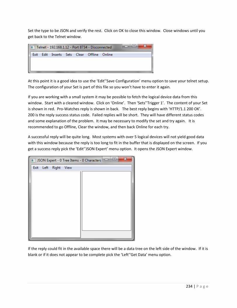
234 | P a g e
Set the type to be JSON and verify the rest. Click on OK to close this window. Close windows until you
get back to the Telnet window.
At this point it is a good idea to use the ‘Edit’’Save Configuration’ menu option to save your telnet setup.
The configuration of your Set is part of this file so you won’t have to enter it again.
If you are working with a small system it may be possible to fetch the logical device data from this
window. Start with a cleared window. Click on ‘Online’. Then ‘Sets’’Trigger 1’. The content of your Set
is shown in red. Pro-Watches reply is shown in back. The best reply begins with ‘HTTP/1.1 200 OK’.
200 is the reply success status code. Failed replies will be short. They will have different status codes
and some explanation of the problem. It may be necessary to modify the set and try again. It is
recommended to go Offline, Clear the window, and then back Online for each try.
A successful reply will be quite long. Most systems with over 5 logical devices will not yield good data
with this window because the reply is too long to fit in the buffer that is displayed on the screen. If you
get a success reply pick the ‘Edit’’JSON Expert’ menu option. It opens the JSON Expert window.
If the reply could fit in the available space there will be a data tree on the left side of the window. If it is
blank or if it does not appear to be complete pick the ‘Left’’Get Data’ menu option.

235 | P a g e
This JSON Data GET will load the reply from the Set directly into the JSON tree control. It can accept a
very large amount of data.
Once the Logical Devices tree data appears on the left side of the JSON expert it’s best to use the
‘Left’’Save Tree’ option to save the data.
The next step is to prune unnecessary data out of the tree. Pruning will save memory and disk space but
more importantly it will speed Corsair’s searches of the data and make for easier monitoring in the
drivers Register Monitor window.
The Logical Devices tree consists of an array of objects. Each object has several values in it. Corsair is
only capable of using 3 of these values. The first is the ‘LogDevID’ string. This is the long difficult-to-type
label that Corsair needs to interpret the messages it gets from Pro-Watch. The other fields are the
‘Description’ and ‘AltDescription’ strings. The special setup data for the driver determines which of
these strings Corsair doors and tags will use. It’s usually best to leave both of them in the file. The rest
of the values in the objects can be pruned if desired. The pruning is accomplished with the special
Delete options that are described for the JSON Expert in the Experts manual.
After the data is pruned the data should be saved in the location where the Corsair driver expects to find
it. In our case it is ‘c:\corsair\json_tree.jst’.
S4100 – Simplex 4100 Xx

236 | P a g e
Serial Stream – Receiving data from a port Background
Many industries routinely allow viewing of real-time control system data from home by operators and
supervisors. This is typically done over the Internet. Installations like power plants may become
vulnerable to cyber-attacks by hackers through these Internet connections. The concern is that the plant
could be shut down or worse.
Software firewalls have been shown to be an inadequate answer as any software that is designed to let
certain people through it can eventually be defeated. Firewalls must constantly be updated with
patches. Many times the need for the patch was discovered because someone has already broken
through the firewall.
One idea that has been suggested is that the plant would install a complete set of redundant
instrumentation. One temperature sensor would be used to operate the process. A second temperature
sensor would be used at the same location to go to a monitor-only computer system that would be
viewable through the Internet. The first disadvantage of this approach is the cost of the extra
instrumentation. The second disadvantage is that the at-home operator needs to see the information
from the sensor that the control system is actually using, not another sensor that may not agree with it.
An Answer
CorsairHMI has several methods to operators to view data. The serial stream driver is designed to allow
remote viewing of process data in situations where security cannot be compromised. One host
CorsairHMI Serial Stream ‘transmit’ computer at the manufacturing location sends a stream of data
down a serial communication line. One or more other CorsairHMI Serial Stream ‘receive’ computers
receive the data and place it on graphic display screens. Both transmit and receive computers can log
data.
The key to the security of this driver is that the transmit CorsairHMI computer only transmits data, it
never receives. The receive line on the serial port of this computer can be left unhooked so there is no
question that the data can only go in one direction. No handshake lines are used. The receive computer
can only see the data. It can never change or effect the configuration of the host in any way. This
effectively provides an impenetrable ‘firewall’ that does not rely on software or passwords for its
security.
The receive CorsairHMI computer can be an MBHR host to share data on the Internet with up to 100
MBHR remotes. It should use a firewall. A hacker may be able to disturb the serial stream receive
computer but never the serial stream transmit computer.
Configuration
The serial stream driver requires a multiple-computer license for the CorsairHMI program.

237 | P a g e
Both transmit and receive computers run a similar application database with different settings in the
computer properties file and driver configuration. At-home MBHR remotes can use copies of the same
database.
The serial stream can go from the transmit unit to the receive unit over up to 4 serial ports. More ports
offer a faster connection.
The serial ports that are used for the system can be on external USB-to-serial converters if desired. It is
highly recommended to use external optical isolation on the data line between the transmit and the
receive computers. This guards against electrical disturbances on one computer effecting the other. A
short run of fiber-optic cable can serve for this isolation. This would require RS-232 to fiber converter
boxes. Ethernet fiber connections are not acceptable.
Operation
When the transmit CorsairHMI starts interface operation it begins streaming characters out of the serial
port as fast as it can beginning with the first tag on the first plc and going on to the last tag on the last
plc. It then repeats the action as long as the interface is running.
Further Security Considerations
Any equipment that is on the same network as the CorsairHMI transmit computer cannot use any
wireless technology. Venders should certify that their equipment does not contain any wireless
capability. Disabled wireless components are not the answer – they should not even be present in the
equipment.
Care should be taken when transferring an updated CorsairHMI application from the transmit computer
to the receive computer using devices such as USB flash drives.
Siemens S7 – S7 PLC over Ethernet Xx
SQL – Database Access Xx

238 | P a g e
String Match – ASCII Input The String Match driver is a receive-only driver that works with ASCII data streams that arrive over a
serial port. The data is unsolicited which means that the Corsair program does not transmit anything to
the remote device to start a conversation. The serial stream is separated into ‘lines’ which are
terminated by one or two termination characters. This is typical of devices that output to a serial
printer. Many fire alarm panels work this way.
The String Match driver looks through the lines for patterns of characters that match characters that it
has in a table. If it sees a proper combination of characters it loads a value into a result data array.
The String Match driver does not search through a stream of data to find a string. It looks for strings at
predefined positions in the data.
A special feature is a reset tag that can be used for force a selected value into the result data array.
Driver Setup Parameters
The String Match driver has some special data setup parameters at the driver level.
The first driver setup parameter is the number of lines per data packet. It can vary from 1 to 10.
The next two setup parameters are the two line termination characters. They are frequently an ASCII
carriage return (13) followed by a line feed (10). If the second termination character is not needed it
must be set to zero. If both are set to zero the driver assumes a single carriage return as the terminator.
The next setup parameter is a Yes/No option to force everything to Upper-Case (capital) letters on
receive. This parameter does not capitalize the match strings in the auxiliary databases. The developer
must make sure that the case entered for these strings is correct.
The next four setup parameters are up to 4 characters that can be stripped out of the incoming ASCII
stream. They are set to zero if they are not used.
The driver will always strip out 0 (NULL) characters. This action is not adjustable.
It is recommended that the first termination character be set to a carriage return(13) and that line feeds
(10) be stripped out. That way the driver will work correctly if the incoming stream has either a single
carriage return or a carriage return-line feed combination in either order.
There is a Yes/No parameter that is set to yes for the driver to skip blank lines. If it is set to No blank
lines may appear in the line list.
Data Source Setup Parameters
The String Match driver has some special data setup parameters at the Data Source level.

239 | P a g e
The first option is the integer value that is used for a reset.
The next parameter is a reset time delay.
The next parameter is a Yes/No parameter to allow more than one match to occur when a line is
received. If it is set to No the matching engine
Reserved Tag Addresses
The ‘Reset’ tag is a switch that can be manipulated by Corsair scripts as desired. It is initialized at ‘Off’
when the interface is started.
The ‘Value Array’ tag is an array of unsigned integers that is controlled by the incoming serial stream. It
is initialized at all zeros when the interface is started.
Action Match 1 Line Action Match 1 Position Action Match 1 String
Action Match 2 Line Action Match 2 Position Action Match 2 String
Action Match 3 Line Action Match 3 Position Action Match 3 String
Action Match Name
Action Match Value
Action Match All
Index Match 1 Line Index Match 1 Position Index Match 1 String
Index Match 2 Line Index Match 2 Position Index Match 2 String
Index Match 3 Line Index Match 3 Position Index Match 3 String
Index Match Name
Index Match Value
The Match Line tags are integer tags that hold line numbers. The Match Line value can be from 1 to 10.
If the Match Line value is zero that match is not used.
The Match Position tags are integer tags that hold character position numbers. The first character
position on a line is position 1 (not zero). Valid values are from 1 to 250. If the Match Position value is
zero that match is not used.
The Match String tags are string tags that hold the strings that the Matching Engine looks for on the
Match Line at the Match Position. Up to 3 strings can be used to qualify a match.
The Match Name tags are string tags that are used to enter description of auxiliary database records.
The Matching Engine does not use these tags.

240 | P a g e
The Action Match Value is the value that will be copied into the ‘Value Array’ when there is a match.
The Index Match Value is the index into the Value Array where the Value is put.
The Action Match All tag is a switch that is normally left in the Off position.
Auxiliary Databases
The driver supports 2 auxiliary databases. The first one describes the action matches, the second
describes the index matches.
The Action Match auxiliary database is used to enter data into the following tags:
Action Match 1 Line Action Match 1 Position Action Match 1 String
Action Match 2 Line Action Match 2 Position Action Match 2 String
Action Match 3 Line Action Match 3 Position Action Match 3 String
Action Match Name
Action Match Value
Action Match All
The Index Match auxiliary database is used to enter data into the following tags:
Index Match 1 Line Index Match 1 Position Index Match 1 String
Index Match 2 Line Index Match 2 Position Index Match 2 String
Index Match 3 Line Index Match 3 Position Index Match 3 String
Index Match Name
Index Match Value
Driver Logic
Incoming serial data is divided into distinct lines as determined by the one or two line termination
characters. The driver keeps a list of 10 received lines of up to 250 characters each. When it gets a new
line it shifts the old lines down the list and adds the new line at the top of the list. The termination
characters do not appear in the list. The line is then case-corrected to capital letters and characters are
stripped out as specified by the driver setup parameters. The list is initialized with empty zero-length
strings.
The lines in the list are then submitted to the Matching Engine part of the driver software. As each new
line comes in it goes into the list and the Matching Engine gets another chance to look for matches.

241 | P a g e
For example, assume that another computer is sending the string ‘AAA’ followed by a carriage return,
then the string ‘BBB’, then the string ‘CCC’ and so on.
When the first string is received the Matching Engine works on:
‘AAA’ Empty Empty Empty
When the next string is received the Matching Engine works on:
‘BBB’ ‘AAA’ Empty Empty
As strings come in the Matching Engine sees the following sets of lines:
‘CCC’ ‘BBB’ ‘AAA’ Empty
‘DDD’ ‘CCC’ ‘BBB’ ‘AAA’
‘EEE’ ‘DDD’ ‘CCC’ ‘BBB’
Note that each line is always moved down one position when a new line comes in. The list of lines is not
emptied out when a match is found.
Matching Engine Logic
The driver has two sets of match data – an Action set and an Index set. The Action set is used to
determine what the driver does with the Value Array. The Index set is used to determine which element
of the Value Array the driver works with. Each set can match up to 3 strings.
Let’s assume a fire alarm with 5 smoke detectors. The fire alarm panel sends out two possible status
strings, ‘Alarm’ and ‘Clear’ for each detector. The Value Array is to be set to 1 on an alarm and to 0 on
clear. There are two records in the Action Match database. The first is the string ‘Alarm’ with the
proper Action Match Line and Action Match Position. The Action Match Value is set to 1. The second
record is the string ‘Clear’ with the proper Action Match Line and Action Match Position. The Action
Match Value is set to 0.
The Index Match database has 5 records. Each has a Match String or Strings for the smoke detectors.
One Index Match 1 String may be ‘Building A’ with an Index Match 2 String of ‘Smoke 027’. The Index
Match Values would range from 1 to 5. These correspond to the index in the Value Array for each
smoke. The Value Array must have a size of at least 6 to allow indexes from 0 to 5. The Action Match All
switch is left in the Off position for each record.
The Matching Engine will search through the entire Action and Index match databases to make as many
matches as it can when a new line is received. It is possible for a single line of characters to control
several changes in different elements of the Value Array.
Action Match All Operation

242 | P a g e
Normally the Matching Engine must find from 1 to 3 match strings in the Action Match database. It then
looks for from 1 to 3 match strings in the Index Match database to find out what element of the Value
Array is to be changed. The Action Match All switch offers a different type of operation when it is
turned on. In that case the Action Match Value is applied to all elements of the Value Array. The Index
Match database is not used for Action Matches whose All switch is turned On. A message containing the
string ‘Panel Reset’ could be used to fill the entire Value Array with zeros.
Reset Action
The Reset switch is used to force all of the elements of the Value Array to a fixed value. The value is a
special setup parameter for the Data Source.
TBD – define the operation of the timing parameters
Using Multiple Data Sources
Each data source on the String Match driver can have a full set of tags. The auxiliary database data on
one data source is not used to match data for another data source. One data source could be used for
alarm conditions on smoke detectors. Another could be used for trouble conditions on the same smoke
detectors.
Monitoring the Driver
The communications trace window can be used to examine the incoming data stream. It shows the
complete set of incoming characters including terminators before any capitalization or stripping of
characters occurs. The Data Source register monitoring window shows the contents of the last 10
received lines after this processing has occurred.
Telecor T3 – T3-SC Intercom Xx
VICON – Vicon Video Switching The VICON driver is used to operate a Vicon video switcher from the Corsair interface. It come with any
license for the Corsair program. A corrections license is not required. The documentation for the Vicon
driver is contained in the CorsairHMI Corrections manual.

243 | P a g e
Placement Tasks The development manual describes different types of placement actions. Actions correspond to what
the computer does when the operator clicks on the placement. One of the actions is ‘Task’ where the
computer performs a task. The Target Task window is used to specify the type of task.
The top selector is used to specify the type of the task. The value, script, and tag controls are defined by
what task is selected. The flowing list tells of the available placement tasks with a description of each.
Add Value Xxxx
Alarm List xxxxxx
Block Monitor xxxxxx
Block Setup xxxxxx

244 | P a g e
Change Operator Levels xxxxxx
Change Password xxxxxx
Change PIN xxxxxx
Clean Screen xxxxxx
Close Window xxxxxx
Code Entry Pad xxxxxx
Create Note xxxxxx
CSV File xxxxxx
CSV File Directory xxxxxx
Decrement Xxxxx

245 | P a g e
Do Global Report xxxxxx
Do Local Report xxxxxx
Email Contact List xxxxxx
Increment xxxxxx
Global Report Window xxxxxx
Local Report Window xxxxxx
Log Events xxxxxx
Log Off xxxxxx
Log On xxxxxx

246 | P a g e
Model Selector xxxxxx
Monitor Registers xxxxxx
Name Finder xxxxxx
Open File xxxxxx
Print Screen - Default Printer xxxxxx
Print Screen – Select Printer xxxxxx
Quick Log Off xxxxxx
Save .CAP File xxxxxx
Scan Network xxxxxx
Screen History View xxxxxx

247 | P a g e
See List of Users xxxxxx
Set Data Source Clocks xxxxxx
Set Hook Codes xxxxxx
Set Value xxxxxx
Start Program xxxxxx
Stop Program xxxxxx
Subtract Value xxxxxx
Text File xxxxxx
Text File Directory xxxxxx

248 | P a g e
Toggle xxxxxx
Turn Off xxxxxx
Turn On xxxxxx
View Aux Database xxxxxx
View CIP Devices xxxxxx
View Events xxxxxx
View History xxxxxx
View Global Report Events xxxxxx
View Local Report Events xxxxxx
xxxxxxx

249 | P a g e
Block Reference A program block is a section of the CorsairHMI program that may be used by the developer to perform a
specific function. Standard blocks are blocks that come with the program. Some of them are very
general in their purpose so they can be used in a wide variety of applications. Some of they are very
specialized and more complex. A properly applied block can solve problems that would be very difficult
to do with a conventional interface.
Blocks can be solved with 5 different actions – ‘Off’, ‘Startup’, ‘Init’, ‘Forward’, and ‘Reverse’. Most
commonly the Forward action is used. Unless noted otherwise, the description of the block is describing
the Forward action. Block results are never communicated to live tags with the Off or Startup actions.
Most blocks do not have all 5 actions. Few blocks have the Reverse action.
If a block is assigned directly to a tag, alarm, or call the actions are executed as follows:
When the interface is off the Off action is executed repeatedly.
During the block startup delay period the Startup action is executed repeatedly.
After the startup delay period the Init action is executed exactly one time.
After Init the Forward action is executed repeatedly.
After Init the Reverse action is executed as needed.
If a block is assigned to a script step the actions are executed as follows:
When the interface is off the Off action is executed repeatedly.
During the script startup delay period the Startup action is executed repeatedly.
Whenever the script is started the Init action is executed exactly one time.
Whenever the script step is reached the Forward action is executed.
The Reverse action is not executed.
The script Off and Startup actions are executed whether or not the script has auto-start enabled and
whether or not it is enabled for the computer’s base session. If a script runs at 2-second intervals all of
its blocks will execute the Init action every two seconds. If a script repeatedly jumps back to an earlier
step it does not restart and the Init action is not repeated.

250 | P a g e
Standard Blocks
Absolute Value
This block is used to find the absolute value of each of the elements in an array and put it in a result
array. The action is repeated for a total of PJ elements.
Result: Absolute Value Result (Size PJ + PI)
Parameter Label Type Format
PA Enable Indicator
PB
PC Input Value Array (Size PJ + PD) Double Float -12.5
PD Input Value Start Index Double Int U6.0
PE
PF
PG
PH
PI Result Array Start Index Double Int U6.0
PJ Count (>=1) Double Int U6.0
Assume that PD=2, PI=5, and PJ=3.
PC[2] = -6 PC[3] = 12 PC[4] = -2
When enabled the block will do the following:
Result[5] = 6 Result[6] = 12 Result[7] = 2
Adapter Status
The Adapter Status block is used by the Corsair program to monitor the status of a network adapter.
The interface to the block is through one Result parameter and 10 parameters that are labeled PA
through PJ.
Result: Status Value
Parameter Label Type Format

251 | P a g e
PA Enable Indicator
PB Friendly Name String
Result Adapter Status
PA Block Enable
PB Adapter Friendly Name
PC-PJ Not used
The Adapter Status result is an integer value.
The PA block enable input is a switch. If it is off the block is not active. If it comes on the block reads the
status of the adapter and place the value in the result parameter.
The PB task name is a string that holds the friendly name of the adapter. This name can be determined
using the Computer Network Adapter Summary of the Corsair TCP Expert.
Addition
This block is used to add elements in the PC array to elements in the PF array and put the sum in the
result array. The action is repeated for a total of PJ elements.
Result: Sum Array (Size PJ + PI)
Parameter Label Type Format
PA Enable Indicator
PB
PC First Addend Array (Size PJ + PD)
Double Float -12.5
PD First Addend Start Index Double Int U6.0
PE
PF Second Addend Start Array (Size PJ + PG)
Double Float -12.5
PG Second Addend Start Index Double Int U6.0
PH
PI Sum Array Start Index Double Int U6.0
PJ Count (>=1) Double Int U6.0
Assume PD=2, PG=3, PI=4, and PJ=3
PC[2]= 2.3 PC[3]= -4.6 PC[4]= 23.2

252 | P a g e
PF[3]= 1.5 PF[4]= 2.7 PF[5]= 12.8
When enabled the block will do the following:
Result[4]=3.8 Result[5]=-1.9 Result[6]=36.0
Alarm 1 to 4
This block is used to load single data bits into the status and latch bits of Alarm or Call data structures.
The Result parameter should be a 4-bit Alarm or 4-bit Call data type. The Latching switch determines
how it controls the Status and Latch bits of the Result data.
Result: Destination 4-bit Data (Size PJ + PI)
Parameter Label Type Format
PA Enable Indicator
PB
PC Input Bit Array (Size PJ + PD) Switch
PD Input Bits Start Index Double Int U6.0
PE Invert Input Switch
PF Latching Action Switch
PG Persistent Switch
PH
PI Result Array Start Index Double Int U6.0
PJ Count (>= 1) Double Int U6.0
Alarm Tag Active
This block is used to turn on a Boolean tag when the CorsairHMI model has at least one
unacknowledged alarm or call within five indexes of an alarm or call tag. The optional PH parameter is
for a Boolean memory tag that is turned on if at least one alarm is preset whether it is acknowledged or
not.
Result: At least one is not acknowledged
Parameter Label Type Format
PA Enable Indicator
PB
PC Alarm or Call Tag 1-bit Alarm Data
PD
PE
PF

253 | P a g e
PG
PH At least one is Active Indicator
PI Result Array Start Index Double Int U6.0
PJ
Array Distributor
This block copies values from the PF code value array into elements of the result array. This distribution
is controlled by codes in the PC array.
Result: Values Distributed According to Code (Size PJ + PI)
Parameter Label Type Format
PA Enable Indicator
PB
PC Code Array (Size PJ + PD) Integer U5.0
PD Code Start Index Double Int U6.0
PE
PF Code Value Array (Size PJ + PG) Double Float -12.5
PG Code Value Start Index Double Int U6.0
PH
PI Distribute Result Array Start Index Double Int U6.0
PJ Result Array Size Double Int U6.0
Assume PD=3, PG=4, PI=5, and PJ=4
PC[3]= 3 PC[4]= 0 PC[5]=1 PC[6]= 1
PF[4]= 12.3 PF[5]= 14.6 PF[6]= 2.8 PF[7]= 9.3 PF[8]= 14.6
When enabled, the block will do the following:
Result[5]= 9.3 Result[6] = 12.3 Result[7]= 14.6 Result[8]= 14.6
Pseudo-Code:
For (Loop=0; Loop<PJ; Loop++}
Result[PI + Loop] = PF[PF + PC[PD + Loop]]
Array Element Selector
This block is used to switch values from two input arrays into a third array. It does each element
separately. If the PB input switch is Off the block copies a value from the PD Off array to the result

254 | P a g e
array. If the PB input switch is On the block copies a value from the PF On array to the result array. The
action is done a total of PJ times.
Result: Result of the selection (Size PJ + PI)
Parameter Label Type Format
PA Enable Indicator
PB Selector Switches Array Switch
PC Selector Switches Start Index Double Int U6.0
PD Off Selection Array (Size PJ + PE) String
PE Off Array Start Index Double Int U6.0
PF On Selection Array (Size PJ + PG) String
PG On Array Start Index Double Int U6.0
PH
PI Result Array Start Index Double Int U6.0
PJ Count (>= 1) Double Int U6.0
Assume PC=2, PE=3, PI= 5, and PJ=4
PB[2]=Off PB[3]=On PB[4]=Off PB[5]=On
PD[3]=2.3 PD[4]=3.7 PD[5]=12.2 PD[6]=8.2
PF[4]=1.5 PF[5]=5.9 PF[6]=6.3 PF[7]=16.4
When Enabled the block will act as follows:
Result[5]=2.3 Result[6]=5.9 Result[7]=12.2 Result[8]=16.4
Pseudo Code:
FOR (Loop=0; Loop<PJ; Loop++) {
IF(PB[PC +Loop] > 0.5 THEN
Result[PJ + Loop] = PJ{PG + Loop]
ELSE
Result[PJ + Loop] = PD[PE + Loop]
}
Array Expansion
This block is used to copy each of PJ elements of a source array into PF elements of a destination array.
Result: Expanded Array (Size PF * PJ + PI)

255 | P a g e
Parameter Label Type Format
PA Enable Indicator
PB
PC Value Array (Size PJ + PD) String
PD Value Array Start Index Double Int U6.0
PE
PF Number of expanded values per input (>= 1) Double Int U6.0
PG
PH
PI Result Array Start Index Double Int U6.0
PJ How many input values to expand (>= 1) Double Int U6.0
Assume PD=7, PF=4, PI=2, and PJ=5
PC[7]=8 PC[8]=5 PC[9]=7 PC[10]=9 PC[11]=2
When enabled the block will do the following
Result[2]=8 Result[3]=8 Result[4]=8 Result[5]=8
Result[6]=5 Result[7]=5 Result[8]=5 Result[9]=5
Result[10]=7 Result[11]=7 Result[12]=7 Result[13]=7
Result[14]=9 Result[15]=9 Result[16]=9 Result[17]=9
Result[18]=2 Result[19]=2 Result[20]=2 Result[21]=2
Array Fill
This block is used to fill PJ values in the result array with the single source value that is at PC[PD].
Result: Result Array (Size PJ + PI)
Parameter Label Type Format
PA Enable Indicator
PB
PC Source Value (Size PD + 1) String
PD Souce Index (only 1 element is used) Double Int U6.0
PE
PF
PG
PH
PI Result Array Start Index Double Int U6.0

256 | P a g e
PJ Count (>= 1) Double Int U6.0
Assume PD=3, PI=2, PJ=6, and PC[3]=12
PC[0]=9 PC[1]=10 PC[2]=11 PC[3]=12 PC[4]=13
When enabled the block will do the following:
Result[2]=12 Result[3]=12 Result[4]=12
Result[5]=12 Result[6]=12 Result[7]=12
Pseudo Code:
For (Loop=0; Loop<PJ; Loop++)
Result [PI + Loop] = PC[PD]
Array Maximum
This block is used to find the maximum of the elements in an array.
Result: Maximum (Size PI + 1)
Parameter Label Type Format
PA Enable Indicator
PB
PC Value Array String
PD Value Array Start Index Double Int U6.0
PE
PF Count how many elements are at maximum Double Int U6.0
PG Index to First Maximum Element Double Int U6.0
PH
PI Result Index Double Int U6.0
PJ Value Array Element Count Double Int U6.0
Array Minimum
This block is used to find the minimum of the elements in an array
Result: Minimum (Size PI + 1)
Parameter Label Type Format
PA Enable Indicator
PB

257 | P a g e
PC Value Array String
PD Value Array Start Index Double Int U6.0
PE
PF Count how many elements are at minimum Double Int U6.0
PG Index to First Minimum Element Double Int U6.0
PH
PI Result Index Double Int U6.0
PJ Value Array Element Count Double Int U6.0
Array Totalization
This block is used to totalize values in an array and store the results in another array. The values to be
added together are in PC. This parameter is a series of PJ sub-arrays each having a length of PF. Each of
these sub-arrays is individually totalized and the sum is placed in an element of the result. PJ elements
of the result are loaded with these total values. Most simple totalizations will set PD to 0, and PJ to 1.
Result: Array of Totals (Size PJ + PI)
Parameter Label Type Format
PA Enable Indicator
PB
PC Value Array (Size PF * PJ + PD) Double Float -12.5
PD Value Array Start Index Double Int U6.0
PE
PF Number of Values per Total (>= 1) Double Int U6.0
PG
PH
PI Total Array Start Index Double Int U6.0
PJ Count of Totals (>= 1) Double Int U6.0
Assume that Pd=3, PF=3, PI=5, and PJ=4. This means that PC contains 4 sub-arrays, each of which is 3
elements long. PC must contain at least 15 elements. Values are as follows:
PC[3]=5 PC[6]=13 PC[9]=6 PC[12]=15
PC[4]=12 PC[7]=4 PC[10]=11 PC[13]=10
PC[5]=9 PC[8]=12 PC[11]=14 PC[14]=8
When enabled the block will totalize each 3-element group into an element of the result array. The
action is repeated a total of 4 time to yield:
Result[5]=26 Result[6]=29 Result[7]=31 Result[8]=33
Pseudo Code:

258 | P a g e
For (M=0; M<PJ; M++) {
Total=0.0;
For (N=0; N<PF; N++)
Total = Total + PC[M * PF +N +PD]
Result[PJ + M] = Total;
}
Aux DB Strings
This block is used to load string from an auxiliary database
Result: Strings (Size PJ + PI)
Parameter Label Type Format
PA Enable Indicator
PB Input Value Array Double Int U6.0
PC Input Value Start Index Double Int U6.0
PD Input Value Count Double Int U6.0
PE Code Number Tag Double Int U6.0
PF Field 0-3 Double Int U6.0
PG On for ?? If not found Switch
PH
PI Result Array Start Index Double Int U6.0
PJ Result Array size (>= 1) Double Int U6.0
BattState
This block contains proprietary logic for use with battery monitoring systems. It only works on
CorsairHMI systems, adhere to BMS logic option if selected.
Result: Indications (Size 3-16)
Parameter Label Type Format
PA Current Double Float -12.5
PB Voltage Double Float -12.5
PC Current Setpoints (Size 4) Double Float -12.5
PD Voltage Setpoints (Size 4) Double Float -12.5
PE Time Setpoints (Size 8) Double Int Msec

259 | P a g e
PF Option Switches (Size 2) Switch
PG Timers (Size 7) Double Int Msec
PH
PI
PJ
Bit Index Collector
This block is used to search through an array of bits to see which ones of them are on. The indexes of
the On bits are packed into the integer result array. The rest of the result array is set to zero. PH is used
to return the number of elements of the result array that are in use. PG is used to set a block of
indicators corresponding to the elements of the result array with index values.
Result: Bit Index Table (Size PJ + PI)
Parameter Label Type Format
PA Enable Indicator
PB
PC Bit Array (Size PE + PD) Indicator
PD Bit Array Start Index Double Int U6.0
PE Bit Array Size Double Int U6.0
PF
PG Result Table Indicators Array (Size PJ) Indicator
PH Result Table Element Count Double Int U6.0
PI Result Array Start Index Double Int U6.0
PJ Size of Result Array Double Int U6.0
Bit Split
This block is used to split a group of bits into separate values
Result: Separated Bit Data
Parameter Label Type Format
PA Enable Indicator
PB
PC
PD
PE
PF
PG

260 | P a g e
PH
PI Result Array Start Index Double Int U6.0
PJ
Bitwise AND
This block is used to AND each of the bits in a PC value with the bits of the PF value and place that value
into the result. The action is repeated for a total or PJ elements.
Result: ANDed Output Array (Size PJ + PI)
Parameter Label Type Format
PA Enable Indicator
PB
PC First Value Array (Size PJ + PD) Indicator
PD First Value Start Index Double Int U6.0
PE
PF Second Value Array (Size PJ + PG) Indicator
PG Second Value Start Index Double Int U6.0
PH
PI Result Array Start Index Double Int U6.0
PJ Count (>= 1) Double Int U6.0
Assume that PD=2, PG=3, PI=4, and PJ=3
PC[2] = 4 (0100) PC[3]= 10 (1010) PC[4]=5 (0101)
PF[3] = 5 (0101) PF[4] = 7 (0111) PF[5]= 11 (1011)
When enabled the block would do the following:
Result[4]=4 (0100) Result[5]=2 (0010) Result[6]=1 (0001)
(Values are shown in decimal and binary)
Bitwise NOT
This block is used to invert the bits of a value in the PC array and place that value into the result. The
action is repeated for a total of PJ elements.
Result: Inverted Output Array (Size PJ + PI)
Parameter Label Type Format
PA Enable Indicator

261 | P a g e
PB
PC Value Array (Size PJ + PD) Indicator
PD Value Start Index Double Int U6.0
PE
PF
PG
PH
PI Result Array Start Index Double Int U6.0
PJ Count (>= 1) Double Int U6.0
Assume that PD=2, PI=4, and PJ=2
PC[2]=4 (0100) PC[3]=10 (1010)
When enabled the block would do the following:
Result[4]=1111111111111011 Result[5]=1111111111110101
(Results are shown in binary)
Bitwise OR
This block is used to Or each of the bits in a PC value with the bits of the PF value and place that value
into the result. The action is repeated for a total of PJ elements.
Result: ORed Output Array (Size PJ + PI)
Parameter Label Type Format
PA Enable Indicator
PB
PC First Value Array (Size PJ + PD) Indicator
PD First Value Start Index Double Int U6.0
PE
PF Second Value Array (Size PJ + PG) Indicator
PG Second Value Start Index Double Int U6.0
PH
PI Result Array Start Index Double Int U6.0
PJ Count (>= 1) Double Int U6.0
Assume that PD=2, PG=3, PI=4, and PJ=3

262 | P a g e
PC[2]=4 (0100) PC[3]=10 (1010) PC[4]=5 (0101)
PF[3]=5 (0101) PF[4]= 7 (0111) PF[5]=9 (1001)
When enabled the block would do the following:
Result[4]=5 (0101) Result[5]=15 (1111) Result[6]=13 (1101)
(Values are shown in decimal and binary)
Bitwise XOR
This block is used to Exclusive Or each of the bits in a PC value with the bits of the PF value and place
that value into the result. The action is repeated for a total of PJ elements.
Result: XORed Output Array (Size PJ + PI)
Parameter Label Type Format
PA Enable Indicator
PB
PC First Value Array (Size PJ + PD) Indicator
PD First Value Start Index Double Int U6.0
PE
PF Second Value Array (Size PJ + PG) Indicator
PG Second Value Start Index Double Int U6.0
PH
PI Result Array Start Index Double Int U6.0
PJ Count (>= 1) Double Int U6.0
Assume that PD=2, PG=3, PI=4, PJ=3
PC[2]=4 (0100) PC[3]=10 (1010) PC[4]=5 (0101)
PF[3]=5 (0101) PF[4]=7 (0111) PF[5]=9 (1001)
When enabled the block would do the following:
Result[4] = 1 (0001) Result[5]=13 (1101) Result[6]=12 (1100)
(Values are shown in decimal and binary)
Bound to Limits
This block is used to bind a value between two limits. If the PB input value is under the PE minimum, PE
is transferred to the result. If it is over the PF maximum, PF is transferred to the result. If it is between

263 | P a g e
PE and PF then PB is transferred unchanged to the result. The action is repeated for a total of PJ
elements. PB and the result may be set to the same place if PC and PI are set to be equal.
The PE minimum and PF maximum may be single values that are used with each element of the input
array. In this case PG is set to one. PE and PF may also be arrays of values allowing different min and
max values for each element. In that case PG should be set to be equal to PJ.
Result: Limited Result (Size PJ + PI)
Parameter Label Type Format
PA Enable Indicator
PB Value Input Array (Size PJ + PC) Double Float -12.5
PC Input Start Index Double Int U6.0
PD
PE Minimum Limit (Size PG) Double Float -12.5
PF Maximum Limit (Size PG) Double Float -12.5
PG Limits Count (1 or PG) Double Int U6.0
PH
PI Result Array Start Index Double Int U6.0
PJ Count (>= 1) Double Int U6.0
Assume PC=2, PG=3, PI=5, and PJ=3
PB[2]=13.2 PB[3]=-4.0 PB[4]=97.0
PE[0]=12.6 PE[1]= -2.0 PE[2]=1.0
PF[0]=13.8 PF[1]=3.0 PF[2]=4.2
When enabled the block will do the following:
Result[5]=13.2 Result[6]=-2.0 Result[7]=4.2
Assume PC=2, PG=1, PI=5, and PJ=3
PB[2]=0 PB[3]=6 PB[4]=5
PE[0]=3
PF[0]=5
When enabled the block will do the following:
Result[5]=3 Result[6]=5 Result[7]=4

264 | P a g e
Comms Status
This block is used to determine if a data source is online and communicating with the CorsairHMI
computer. It only works with data sources that are using Corsiar devices.
Result: Good Comms Indication (Size PI + 1)
Parameter Label Type Format
PA Enable Indicator
PB Source Tag Indicator
PC Online Delay Time Double Int Msec
PD Offline Delay Time Double Int Msec
PE Online Indication (Size PF + 1) Indicator
PF Online Indication Index Double Int U6.0
PG Offline Indcation (Size PH + 1) Indicator
PH Offline Indication Index Double Int U6.0
PI Result Array Start Index Double Int U6.0
PJ
Control Limits
This block is used to calculate SPC control limits
Result: Standard Diviation
Parameter Label Type Format
PA Enable Indicator
PB Sample Data (Size PC + PJ) Double Float -12.5
PC Sample data Start Index Double Int U6.0
PD
PE
PF Lower Control Limit
PG Center Line
PH Upper Control Limit
PI Result Array Start Index Double Int U6.0
PJ Sample Count (>=3) Double Int U6.0
Count Bits
This block is used to count how many bits of an array are turned on. It does not do anything when the
PA enable parameter is off the array of bits to be counted by parameter PB. The count starts at integer
PC and continues for a total of PS bits. The total number of bits will vary from zero to the value in PJ. It is
stated in PI index of the result. PG is an optional output parameter. If used it must be a script variable in
a memory tag. It retains the index of the first ON bit

265 | P a g e
Result: Count of how many bits are ON (Size PI + 1)
Parameter Label Type Format
PA Enable Indicator
PB Bit Array (Size PC + PJ) Indicator
PC Bit Array Start Index Double Int U6.0
PD
PE
PF
PG Index of first ON bit Double Int U6.0
PH
PI Result Start Index Double Int U6.0
PJ How Many Bits to Examine Double Int U6.0
Counter
This block counts changes in the on-off status of an array of Boolean bit values. Each bit has a separate
count value in a result envoy.
Maximum count speed is system dependent. Most systems should be able to handle up to five counts
per second with equal on and off times. Faster count rates should use extended hardware.
This block does not do anything to limit or reset the resulting count value. Those functions must be
paired in other logic. The monitor value of a count depends on the tag and format of the result. Counts
going over the maximum are undefined.
Result: Counts (Size PJ + PI)
Parameter Label Type Format
PA Enable Indicator
PB
PC Input Bit Array (Size PJ + PD) Indicator
PD Input Array Start Index Double Int U6.0
PE
PF Count on Rise (Size 1) Indicator
PG Count on Fall (Size 1) Indicator
PH
PI Result Array Start Index Double Int U6.0
PJ Count (>= 1, <= 400) Double Int U6.0
Daily Average
This block is used to average daily values; it also rejects values under the minimum.
Result: Average (Size PI + 4)

266 | P a g e
Parameter Label Type Format
PA Enable Indicator
PB Value List (Size PC + PD) Double Float -12.5
PC Value Start Index Double Int U6.0
PD Value Array Size Double Int U6.0
PE
PF Minimum Value Double Float -12.5
PG
PH Returned Count Double Int U6.0
PI Result Start Index Double Int U6.0
PJ
Result[0 + PI] is the average
Result[1 + PI] is the total
Result[2 + PI] is the lowest
Result[3 + PI] is the highest
Daily Production
This block rolls-over daily production totals
Result: Table of daily values (Size PF * PJ + PI)
Parameter Label Type Format
PA Enable Indicator
PB Time Setpoints (Size PC) Integer AM/PM
PC Time Setpoint Size (1-160) Double Int U6.0
PD Transfer Data Indicator Indicator
PE
PF Number of Values Per Day (>= 1) Double Int U6.0
PG Use PH Time? Indicator
PH Special Time Integer AM/PM
PI Result Array Start Index Double Int U6.0
PJ Count of Days (>= 1) Double Int U6.0
Debounce
This block debounces timing

267 | P a g e
Result: Debounced Status (Size PJ + PI)
Parameter Label Type Format
PA Enable Indicator
PB
PC Input Array (Size PJ + PD) Indicator
PD INPut Array Start Index Double Int U6.0
PE
PF On Time Delay (Size 1) Double Int Msec
PG Off Time Delay (Size 1) Double Int Msec
PH
PI Result Array Start Index Double Int U6.0
PJ Count (1-200) Double Int U6.0
Descending Transfer
This decreases index order is a reaunerate when shifts data force in an array. Assume a tag needs
‘values’ with a size 10. It may be reduced to copy element 0 to element 1, element 1 to 2 and so on. If
this is done with a normal transfer or the entire array will be filled with the entity of element 0. The
descending transfer block copies the elements in the correct order.
Result: Destination Array (Size PJ + PI)
Parameter Label Type Format
PA Enable Indicator
PB
PC Input Value Array (Size PJ + PD) String
PD Input Value Start Index Double Int U6.0
PE
PF
PG
PH
PI Result Array Start Index Double Int U6.0
PJ Count (>= 1) Double Int U6.0
Division
This block is used to divide elements in the PC array by elements in the PF array and put the quotient in
the results array. The action is repeated for a total of PJ elements.
Result: Quotient Array (Size PJ + PI)

268 | P a g e
Parameter Label Type Format
PA Enable Indicator
PB
PC Dividend Array (Size PJ + PD) Double Float -12.5
PD Dividend Start Index Double Int U6.0
PE
PF Divisor Array (Size PJ + PG) Double Float -12.5
PG Divisor Start Index Double Int U6.0
PH
PI Quotient Array Start Index Double Int U6.0
PJ Count (>= 1) Double Int U6.0
Assume PD=2, PG=3, PI=4, and PJ=3
PC[2]=9 PC[3]=-4 PC[4]=6
PF[3]=3 PF[4]=2 PF[5]=0.5
When enabled the block will do the following:
Result[4]=3 Result[5]=-2 Result[6]=12
Equal To
This block is used to control a result array of indicators based upon comparison of elements in two
arrays. If the elements in the PC array is equal to the element in the PF array the result is turned On.
Otherwise it is turned off. This action is done a total of PJ times. This block is not recommended for use
with floating-point values. The Within Limits block may be a better choice for these situations.
Result: Indicator Output Array (Size PJ + PI)
Parameter Label Type Format
PA Enable Indicator
PB
PC First Value Array (Size PJ + PD) String
PD First Value Start Index Double Int U6.0
PE
PF Second Value Array (Size PJ + PG) String
PG Second Value Start Index Double Int U6.0
PH
PI Result Array Start Index Double Int U6.0
PJ Count (>= 1) Double Int U6.0

269 | P a g e
Assume that PD=2, PG=3, PI=4, and PJ=3
PC[2]=4 PC[3]=27 PC[4]=5
PF[3]=5 PF[4]=27 PF[5]=9
When enabled the block would do the following:
Result[4]=Off Result[5]=On Result[6]=Off
Falling Trigger
This block is used for falling edge detection of the state of an indicator. When the PA input value goes
from 1 to 0 the result indicator is set to one until the next execution of the block.
Result: Falling edge detected flag (Size PI + PJ)
Parameter Label Type Format
PA Input Bit (Size PB + PJ) Indicator
PB Input Index Double Int U6.0
PC
PD
PE
PF
PG
PH
PI Result Index Double Int U6.0
PJ Count (>= 1, <=800) Double Int U6.0
Scans of the block would work like this:
Scan 1 PA[PB]=Off Result[PI]=Off Scan 2 PA[PB]=On Result{PI]=Off Scan 3 PA[PB]=Off Result[PI]=On Scan 4 PA[PB]=Off Result[PI]=Off Scan 5 PA[PB]=On Result[PI]=Off Scan 6 PA[PB]=On Result[PI]=Off Scan 7 PA[PB]=Off Result[PI]=On Scan 8 PA[PB]=Off Result[PI]=Off
Fix Strings
This block is used to modify an array of strings with several options. The options are executed in
parameter order from PC through PH. PC and PD are used to force the letters in the string to be all

270 | P a g e
upper or lower case. If both PC and PD are on the result they will be in the lower. PE is turned on to
remove leading and trailing spaces and control characters from the string. PF is similar except that they
can be removed from anywhere, not just at the beginning and end. PG is turned on for adding spaces to
the end to force the string to its full allocated length. If PH is On all characters except numbers, decimal
places, and the minus sign are removed. In order for strings to be fixed in-place PB must be set to the
same place as the result and PI must be set to zero.
Result: Destination String Array (Size PJ + PI)
Parameter Label Type Format
PA Enable Indicator
PB Input String Array (Size PJ) String
PC Force Upper Case Indicator
PD Force Lower Case Indicator
PE Strip Lead and Trail Space Indicator
PF Strip all Space Indicator
PG Space Pad to Length Indicator
PH Strip Non-Numeric Indicator
PI Result Index Double Int U6.0
PJ Count Double Int U6.0
GPS Areas
This block takes location information from a GPS receiver. It has a table of corners of rectangular areas.
It returns an index value telling what area the receiver is currently in. The block also translates the
current position to an XY pair of graphic screen pixel coordinates. This is an array operation that can do
multiple screens. PB, PC, PD, PE, PH, and PI must be fed with 64 bit integer data with the exact format
for this block to work. It will not do type of format translation on these parameters.
Result: Current Area Index (Size 1, Value Range 0 to Areas)
Parameter Label Type Format
PA Enable Indicator
PB Current Latitude 64-bit Integer Latitude
PC Current Longitude 64-bit Integer Longitude
PD Area Latitude Table (Size Areas * 4) 64-bit Integer Latitude
PE Area Longitude Table (Size Areas * 4) 64-bit Integer Longitude
PF Area name Strings (Size Areas + 1) String
PG
PH Screen Latitude Table (Size Screen * 2) 64-bit Integer Latitude
PI Screen Longitude Table (Size Screen * 2) 64-bit Integer Longitude
PJ Returned Pixel Position (Size Screen * 2) Double Int -8

271 | P a g e
GPS Destinations
This block takes location information from a GPS receiver. It has a table of positions of markers. It
returns an index value telling what marker is next.
The block also translates the current position to an XY pair of graphic screen pixel coordinates. This is an
array operation that can do multiple screens.
PB, PC, PD, PE, PH, and PI must be fed with 64 Bit integer data with exact format for this block to work. It
will not do type of format translation on these parameters.
Result: Current Marker Index (Size 1, Value Range 0 to Destination)
Parameter Label Type Format
PA Enable Indicator
PB Current Latitude 64-bit Integer Latitude
PC Current Longitude 64-bit Integer Longitude
PD Destination Latitude Table (Size Markers) 64-bit Integer Latitude
PE Destination Longitude Table (Size Markers) 64-bit Integer Longitude
PF Destination Name String (Size Markers + 1) String
PG Distance to Destination (Meters) Double Float U8.1
PH
PI
PJ
GPS Markers
The GPS Markers Block is a standard Corsair program block that is used with Latitude and Longitude
information from a GPS receiver. It has some similar characteristics to the GPS Areas block except that it
works with ‘Markers’. A Marker is a named point on the surface of the earth with a defined Latitude and
Longitude. The block is fed a table of markers. It determines which marker is closest to the current
position of the GPS.
The blocks result parameter is called the Current Marker Index. If there are no valid markers in the table
the Index is set to zero. If the first marker is the closest the index is set to 1. If the second marker is
closest the index is set to 2.
The block has 10 parameters labeled PA through PJ. PA is the block’s enable control. If it is off the block
does not do anything. Usually PA is set to a constant value of ‘On’.
PB and PC are the current latitude and longitude tags from the GPS data source. They should be the 64-
bit integer type with the special Latitude and Longitude data formats.

272 | P a g e
PD and PE are for the tags that make up the marker latitude and longitude tables. They are typed and
formatted like PB and PC. If a system is sized for up to 100 makers these tags must have a size of at
least 100. Corsair array elements begin with index values of zero so these elements would be indexed
from 0 to 99.
The length of the marker table is determined by the size of the PC and PD tags. If an element of these
tables has a value of 0 for both latitude and longitude the GPS Markers block will skip over that element.
When the block is enabled, if element 6 of the PD and PE table is the closest to the PB and PC GPS
position the block result parameter will be set to a value of 7.
The PF parameter is used for a string tag that has the names of the marker positions. These names are
indexed to align with the current marker index. Note that the marker name in PF[12] corresponds to the
marker position in PD[11] and PE[11]. If the developer desires to show the current marker name on a
screen he can create a value placement of the PF tag indexed by the current marker index result tag.
The PG parameter is used to enter a second tag that is controlled by the block. It must be a memory tag.
It is set to the distance in meters from the current position to the closest marker.
The primary purpose of the GPS markers block is to find the closest marker to the current GPS position.
A second purpose of the block is to translate the GPS coordinates to screen X and Y pixel coordinates.
This feature is used to move icons around the screen as the GPS position changes. Parameters PH, PI,
and PJ are used for this function. The GPS Areas block performs this function exactly the same way as
the GPS Markers block does using the same parameters. The operation of this function is described in a
separate document.
The GPS Markers block has a specialized setup window that can be used by the developer to configure
and monitor the parameter data. The window that is used to assign parameters to the block has a
button marked ‘Setup’ on the lower left. It is used to open the GPS Marker setup window.
The top group of controls on the setup window is related to the current latitude and longitude
coordinates that are coming from the GPS. The developer can temporarily make the tags changeable so
that he can enter coordinates for testing purposes. The window has buttons that are used to open
these entries. The number of the current closest marker, its name, and the distance to it in meters are
all displayed.
The next group of controls on the marker setup window is used to view and change the marker setup
data. The operator enters a nonzero marker number. Its latitude, longitude, and name are displayed.
Buttons allow entry of each item.
The ‘Set’ button is used to copy the current GPS coordinates into a marker. The developer can drive a
vehicle containing the GPS to a marker position. He enters the marker number, hits the ‘Set’ key, and
clicks on ‘Marker Name’ to name the marker. Internet-based mapping software may be another
possibility to get marker coordinate information.

273 | P a g e
There are controls on the marker setup window in a group labeled ‘Screens’. These controls are used to
configure the GPS coordinate to screen pixel position function. They are not covered in this document.
The ‘Solves’ number in the screens control group is used to tune the performance of the markers block.
This number is how many markers are checked with each execution of the block. If the number is zero
all markers are checked. If it is set to 50 the block will check 50 markers on each execution. Low values
may make it so that the computer takes too long to find the closest marker as the GPS moves. A zero or
high value may cause the GPS Markers block to take excessive CPU time.
Parameter Label Type Format
PA Enable Indicator
PB Current Latitude 64-bit Integer Latitude
PC Current Longitude 64-bit Integer Longitude
PD Marker Latitude Table (Size Markers) 64-bit Integer Latitude
PE Marker Longitude Table (Size Markers) 64-bit Integer Longitude
PF Marker Name String (Size Markers + 1) String
PG Distance to Marker (Meters) Double Float U8.1
PH Screen Latitude Table (Size Screens * 2) 64-bit Integer Latitude
PI Screen Longitude Table (Size Screens * 2) 64-bit Integer Longitude
PJ Returned Pixel Positions (Size Screens * 2) Double Int -8
Greater Than
This block is used to control a result array of indicators based upon comparison of elements in two
arrays. If the element in the PC array is greater than the element in the PF array the result is turned On.
Otherwise it is turned off. This action is done a total of PJ times.
Result: Indicator Output Array (Size PJ + PI)
Parameter Label Type Format
PA Enable Indicator
PB
PC First Value Array (Size PJ + PD) String
PD First Value Start Index Double Int U6.0
PE
PF Second Value Array (Size PJ + PG) String
PG Second Value Start Index Double Int U6.0
PH
PI Result Array Start Index Double Int U6.0
PJ Count (>= 1) Double Int U6.0
Assume that PD=2, PG=3, PI=4, and PJ=3

274 | P a g e
PC[2]=4 PC[3]=27 PC[4]=9
PF[3]=5 PF[4]=27 PF[5]=5
When enabled the block will do the following:
Result[4]=Off Result[5]=Off Result[6]=On
Greater Than or Equal To
This block is used to control a result array of indicators based upon comparison of elements in two
arrays. If the element in the PC array is greater than or equal to the element in the PF array the result is
turned On. Otherwise it is turned off. This action is done a total of PJ times.
Result: Indicator Output Array (Size PJ + PI)
Parameter Label Type Format
PA Enable Indicator
PB
PC First Value Array (Size PJ + PD) String
PD First Value Start Index Double Int U6.0
PE
PF Second Value Array (Size PJ + PG) String
PG Second Value Array Start Index Double Int U6.0
PH
PI Result Array Start Index Double Int U6.0
PJ Count (>= 1) Double Int U6.0
Assume that PD=2, PG=3, PI=4, and PJ=3
PC[2]=4 PC[3]=27 PC[4]=9
PF[3]=5 PF[4]=27 PC[5]=5
When enabled the block would do the following:
Result[4]=Off Result[5]=On Result[6]=On
Group Calls
This block is used to set or clear indicators based upon which groups of calls contain activity. The PC
array is an array of calls. It is frequently fed from a tag on an intercom driver. The PE array is a list of
non-zero indexes into the result array. PF and PG contain the start and end indexes of the calls in each
group.

275 | P a g e
Result: Array of Group Indications
Parameter Label Type Format
PA Enable Indicator
PB
PC Call Indications Indicator
PD
PE Result Group List Double Int U7.0
PF First Call of Group Double Int U7.0
PG Last Call of Group Double Int U7.0
PH
PI
PJ
High Alarm
This block is used to set indicators in an array when values in the PB array are greater than values in the
PE setpoint array. The indicators are reset to zero when the PB value drops below the PE value minus
the PG deadband. The reulst array element is not changed if the PB value is less than or equal to PE and
greater than or equal to PE minus PG. The action is repeated a total of PJ times.
Result: Alarm Status (Size PJ + PI)
Parameter Label Type Format
PA Enable Indicator
PB Process Value Array (Size PJ + PC) Double Float -12.5
PC Process Value Start Index Double Int U6.0
PD Any in Alarm Indicator
PE High Setpoint (Size PF) Double Float -12.5
PF Setpoint Count (1 or PJ) Double Int U6.0
PG Deadband (Size PH) Double Float -12.5
PH DeadBand Count (1 or PJ) Double Int U6.0
PI Result Array Start Index Double Int U6.0
PJ Coutn (>= 1) Double Int U6.0
The PD indicator comes on if any of the values are in alarm.
The PE set point and PG deadband may be single values that are used with each element of the PB array.
In this case PF and PH are set to 1. PE and PG can also be arrays of values allowing different set points
and deadbands for each element. In that case PF and PH should be set equal to PJ

276 | P a g e
HOA Call
This block does the HOA control of a tag.
Result: Call Bits (Size PJ + PI)
Parameter Label Type Format
PA Enable Indicator
PB
PC HOA Array (Size PJ + PD) HOA
PD HOA Array Start Index Double Int U6.0
PE
PF Auto Signals (Size PJ + PG) Switch
PG Auto Signals Start Index Double Int U6.0
PH
PI Result Array Start Index Double Int U6.0
PJ Count (>= 1) Double Int U6.0
HOA Position
This block is used to control boolean bit tags based upon the data in a HOA tag. It can operate on
multiple indexes on the HOA tag.
The HOA is a data structure with three bits called Status, Enable, and Hand. The block turns the result on
if the status bit is on. Optional output PE through PH output additional information about the Hand tag.
PE is turned on if the enable bit is on. PF is turned if both the enable and hand bit is on. They can be
script variables or memory tags. PE is turned on if the Enable bit is on. PF is turned on if both the Enable
and Hand bit is on. PG is turned on if both the Enable and hand bits are off. PH is turned on if the Enable
bit is on and the Hand bit is off.
Result: Status Bits (Size PJ + PI)
Parameter Label Type Format
PA Enable Indicator
PB HOA Array (Size PJ + PC) HOA
PC HOA Array Start Index Double Int
PD
PE Is Enabled Output (Size PJ) Switch
PF Is hand Output (Size PJ) Switch
PG Is Off Output (Size PJ) Switch
PH Is Auto Output (Size PJ) Switch
PI Result Array Start Index Double Int U6.0
PJ Count (>= 1) Double Int U6.0

277 | P a g e
HOA Status
This block is used to control…. The block is designed to use only with ?? HOA tags.
It will not ?? when the HOA tag is on a data structure.
Needs review – JA
Result: HOA Switches (Size PJ + PI)
Parameter Label Type Format
PA Enable Indicator
PB Status Inputs Array (Size PJ + PC) Switch
PC Status Inputs Start Index Double Int U.0
PD Set to Hand (Size 1) Switch
PE Shut off Hand Bit (Size 1) Switch
PF Set to Auto (Size 1) Switch
PG Set to Off (Size 1) Switch
PH
PI Result Array start Index Double Int U6.0
PJ Count (>= 1, <= 400) Double Int U6.0
Horizontal Tank
This block is used to calculate the volume of liquid that is in a horizontal cylindrical tank with flat ends. It
needs to know the tank dimensions and the distance that the liquid is up from the bottom. A multiplier
is applied to the result for conversion from cubic volume unit to other units. The final result can be in
units like gallons or pounds.
Result: Volume in multiplied cubic units (Size PI + 1)
Parameter Label Type Format
PA Enable Indicator
PB Liquid Height Double Float -12.5
PC Tank Diameter Double Float -12.5
PD Tank Length Double Float -12.5
PE Result Multiplier Double Float -12.5
PF
PG
PH Cubic Units Double Float -12.5
PI Result Index Double Int U6.0
PJ

278 | P a g e
Hourly Production
This block totalizes production data segregated by time.
Result: Table of Hourly Value (Size PI + PJ)
Parameter Label Type Format
PA Enable Addition (Size PB + 1) Indicator
PB Enable Index Double Int U6.0
PC Amount to Add Double Float -12.5
PD Start time Array (Size PJ) Integer AM/PM
PE End Time Array (Size PJ) Integer AM/PM
PF
PG Use PH Time? Indicator
PH Special Time Integer AM/PM
PI Result Array Start Index Double Int U6.0
PJ Count (>= 1) Double Int U6.0
Ingredient in Use
The block is used with recipes to mark which ingredients of a list are in use on a formula. PC contains an
array of integer values ranging from 0 to PJ minus 1. The block first turns off the result array for a total
of PJ elements. It then zeros out the optional PH array. It then goes to the PD starting index element of
the PC array. If it has an integer value of 4 the block turns on Result[PI+4] to mark that it found the
ingredient code value of 4. It will then add one to the value PH[4] (if PH is used). This totalizes how many
times the ingredient appears the PC list. The result is an On-Off flag marking that it is used somewhere
in the PC list. The block works through a total of PE elements of the PC array.
Result: Array of Indicators (Size PJ + PI)
Parameter Label Type Format
PA Enable Indicator
PB
PC Ingredient Code Array (Size PE + PD) Integer U5.0
PD Ingredient Code Start Index Double Int U6.0
PE Ingredient Code Array Size Double Int U6.0
PF
PG
PH Ingredient Uses Count Result (Size PJ) Integer U5.0
PI Result Array Start Index Double Int U6.0

279 | P a g e
PJ Size of Result Array (>= 1) Double Int U6.0
Assume PD=2, PE=6, PI=3, and PJ=5
PC[2]=4 PC[3]=0 PC[4]=4 PC[5]=2 PC[6]=3 PC[7]=3
When enabled the block will yield the following results:
PH[0]=1 PH[1]=0 PH[2]=1 PH[3]=2 PH[4]=2
Results[3]=On Results[4]=Off Results[5]=On Results[6]=On Results[7]=On
Ingredient Totals
The block is used with recipes to totalize amounts by ingredient. PC contains the ingredient indexes. It is
an array of integer values ranging from 0 to PJ minus 1. The block first zeros the result array for a total of
PJ elements, it then zeros out the optional PH array. It then goes to the PD starting index element of the
PC array. If it has an integer value of 4 the block grabs the amount value PE[PF]. It then adds that
amount to Result[PI+4]. It will then add one to the value in PH[4] (if PH is used). This totalizes how many
times the ingredient appears in the PC array. The result is a total of how much was used.
Result: Array of Totals (Size PJ + PI)
Parameter Label Type Format
PA Enable Indicator
PB
PC Ingredient Code Array (Sizes PG + PD) Integer U5.0
PD Ingredient Code Start Index Double Int U6.0
PE Ingredient Amount Array (Size PG + PF) Double Float -12.5
PF Ingredient Amount Start Index Double Int U6.0
PG Size of Arrays Double Int U6.0
PH Ingredient Uses Count Result (Size PJ) Integer U5.0
PI Result Array Start Index Double Int U6.0
PJ Number of Ingredients Double Int U 6.0
Assume PD=2, PF=3, PG=6, PI=3, and PJ=5
PC[2]=4 PC[3]=0 PC[4]=4 PC[5]=2 PC[6]=3 PC[7]=3
PE[3]=2.8 PE[4]=3.6 PE[5]=12.2 PE[6]=8.4 PE[7]=5.5 PE[8]=4.2
When enabled the block will yield the following results:
PH[0]=1 PH[1]=0 PH[2]=1 PH[3]=2 PH[4]=2

280 | P a g e
Result[3]=3.6 Result[4]=0.0 Result[5]=5.8 Result[6]=9.7 Result[7]=15.0
Initialize
This block is used to fill many values in the result array with a single source value. It only acts on
initialization.
Result: Initialized Result Array (Size PJ + PI)
Parameter Label Type Format
PA
PB
PC Source Value (Size PD + 1) String
PD Source Index (only 1 element is used) Double Int U6.0
PE
PF
PG
PH
PI Result Array Start Index Double Int U6.0
PJ Count (>= 1) Double Int U6.0
Assume PD=3, PI=2,PJ=6, and PC[3]=12
On initialization the block will do the following:
Result[2]=12 Result[3]=12 Result[4]=12
Result[5]=12 Result[6]=12 Result[7]=12
This block is not to be used in programs.
Integrate Pulse
This block integrates the pulse generator
Result: Pulses (Size 2)
Parameter Label Type Format
PA Enabled Indicator
PB Freeze Indicator
PC Analog Value Double Float -12.5
PD Low Threshold Double Float -12.5
PE Pulse Constant Double Float -12.5

281 | P a g e
PF Time Base Double Int Msec
PG Slice Period Double Int Msec
PH
PI Current Accumulation Double Float -12.5
Less Than
This block is used to control a result array of indicators based upon comparison of elements in two
arrays. If the element in the PC array is less than the element in the PF array the result is turned on.
Otherwise it is turned off. This action is done a total of PJ times.
Result: Indicator Ouput Array (Size PJ + PI)
Parameter Label Type Format
PA Enable Indicator
PB
PC First Value Array (Size PJ + PD) String
PD First Value Start Index Double Int U6.0
PE
PF Second Value Array (Size PJ + PG) String
PG Second Value Start Index Double Int U6.0
PH
PI Result Array Start Index Double Int U6.0
PJ Count (>= 1) Double Int U6.0
Assume that PD=2, PG=3, PI=4 and PJ=3
PC[2]=4 PC[3]=27 PC[4]=9
PF[3]=5 PF[4]=27 PF[5]=5
When enabled the block would do the following:
Result[4]=On Result[5]=Off Result[6]=Off
Less Than or Equal To
This block is used to control a result array of indicators based upon comparison of elements in two
arrays. If the element in the PC array is less than or equal to the element in the PF array the result is
turned on. Otherwise it is turned off. This action is done a total of PJ times.
Result: Indicator Output Array (Size PJ + PI)

282 | P a g e
Parameter Label Type Format
PA Enable Indicator
PB
PC First Value Array (Size PJ + PD) String
PD First Value Start Index Double Int U6.0
PE
PF Second Value Array (Size PJ + PG) String
PG Second Value Start Index Double Int U6.0
PH
PI Result Array Start Index Double Int U6.0
PJ Count (>= 1) Double Int U6.0
Assume that PD=2, PG=3, and PJ=3
PC[2]=4 PC[3]=27 PC[4]=9
PF[3]=5 PF[4]=27 PF[5]=5
When enabled the block would do the following:
Result[4]=On Result[5]=On Result[6]=Off
Login Data
This block is used to load tags with data about the currently logged in operator. If it is not enabled, it
does not do anything. The result is to be a boolean bit tag.
Result: Logged – In Indication (Size PI + 1)
Parameter Label Type Format
PA Enable Indicator
PB
PC
PD
PE Authority Level Double Int U6.0
PF
PG Operator Name String
PH
PI Result Array Start Index Double Int U6.0
PJ

283 | P a g e
Login ID
This block is used to log in a user from an ID string.
Result: Logged – In Indication (Size PI + 1)
Parameter Label Type Format
PA Enable Indicator
PB
PC ID String String
PD
PE Alternation Switch
PF
PG Operator Name String
PH
PI Result Array Start Index Double Int U6.0
PJ
Login User
This block is used to log in a user from a string
Result: Logged – In Indication (Size PI + 1)
Parameter Label Type Format
PA Enable Indicator
PB
PC User Name String String
PD
PE
PF
PG Operator Name String
PH
PI Result Array Start Index Double Int U6.0
PJ
Logout
This block is used to log out an operator.
Result: Logged – In Indication (Size PI + 1)
Parameter Label Type Format

284 | P a g e
PA Enable Indicator
PB
PC
PD
PE
PF
PG Operator Name String
PH
PI Result Array Start Index Double Int U6.0
PJ
Lookup Table
This block is used to calculate an array of values using linear interpolation. PB is the array of raw input
values. PE and PF form a table of pairs of input and output values. The block takes a value from the PB
array and finds what elements of the PE array are below and above it. It then uses the corresponding
values in the PF array to interpolate a result. This action is repeated for a total of PJ elements.
The PE and PF tables can be any desired length with a minimum of 2. Their size is PG. The value of the PE
input value table must be in ascending (increasing) order for the block to function correctly. Values in
the PF output value table may be in any order.
Result: Interpolated Output Value (Size PJ + PI)
Parameter Label Type Format
PA Enable Indicator
PB Raw Input Value Array (Size PJ + PC) Double Float -12.5
PC Raw Value Start Index Double Int U6.0
PD
PE Input Value Table (Size PG) Double Float -12.5
PF Output Value Table (Size PG) Double Float -12.5
PG Table Size (>= 2) Double Int U6.0
PH
PI Result Array Start Index Double Int U6.0
PJ Count (>= 1) Double Int U6.0
Low Alarm
This block is used to set indicators in an array when values in the PB array are less than values in the PE
set point array. The indicators are reset to zero when the PB value goes above the PE value plus the PG

285 | P a g e
dead band. The result array element is not changed if the PB value is greater than or equal to PE and less
than or equal to PE plus PG. The action is repeated a total of PJ times.
The PD indicator comes on if any of the values are in alarm.
The PE set point and PG dead band may be single values that are used with each element of the PB
array. On this case PF and PH are set to 1. PE and PG can also be arrays of values allowing different set
points and dead bands for each element. In that case PF and PH should be set equal to PJ.
Result: Alarm Status (Size PJ + PI)
Parameter Label Type Format
PA Enable Indicator
PB Process Value Array (Size PJ + PC) Double Float -12.5
PC Process Value Start Index Double Int U6.0
PD Any in Alarm Indicator
PE Low Setpoint (Size PF) Double Float -12.5
PF Setpoint count (1 or PJ) Double Int U6.0
PG Deadband (Size PH) Double Float -12.5
PH Deadband Count (1 or PJ) Double Int U6.0
PI Result Array Start Index Double Int U6.0
PJ Count (>= 1) Double Int U6.0
Maximum
This block captures the maximum of a changing value. When it is enabled the PC value is checked
against the result to see if it is greater. If it is, it is copied to the result as the new value of the maximum.
This operation is repeated on PJ elements of both the PC and result arrays.
When the block captures anew value of the maximum for the PD starting index it stores the date and
time in a block variable. It may also store it in the PG parameter.
When the PF reset input is on the PC array is copied to the result array and the date and time are stored
in a block variable and optionally in the PH parameter.
Result: Maximum Result (Size PJ + PI)
Parameter Label Type Format
PA Enable Indicator
PB
PC Value Input Array (Size PJ + PD) Double Float -12.5
PD Value Start Index Double Int U6.0
PE

286 | P a g e
PF Reset Input Indicator
PG Date and Time of Start Index Maximum Double Int Ostime
PH Date and Time of Last Reset Double Int Ostime
PI Result Array Start Index Double Int U6.0
PJ Count (>= 1) Double Int U6.0
Min Max Scaling
This block is used to convert an array of raw values into an array of results using straight-line
interpolation between a minimum and a maximum. PD through PG contain the values that define the
scaling. If the PB raw values is greater than the PE raw maximum the result is set to the PG scaled
maximum. The action is repeated a total of PJ times.
PD through PG can each be a single value that is used for all of the elements that are converted. In this
case PH is set to 1. They can also be an array of values allowing different scaling for each element. In this
case PH is set to be equal to PJ.
Result: Scaled Result (Size PJ + PI)
Parameter Label Type Format
PA Enable Indicator
PB Raw Value Array (Size PJ + PC) Double Float -12.5
PC Raw Value Start Index Double Int U6.0
PD Raw Minimum (Size PH) Double Float -12.5
PE Raw Maximum (Size PH) Double Float -12.5
PF Scaled Minimum (Size PH) Double Float -12.5
PG Scaled Maximum (Size PH) Double Float -12.5
PH Min and Max Count (1 or PJ) Double Int U6.0
PI Result Start Index Double Int U6.0
PJ Count (>= 1) Double Int U6.0
Minimum
This block captures the minimum of a changing value. When it is enabled the PC value is checked against
the result to see if it is less. If it is, it is copied to the result as the new value of the minimum. This
operation is repeated on PJ elements of both the PC and result arrays. When the block captures a new
value of the minimum for the PD starting index it stores the date and time in a block variable. It may also
store it in the PG parameter. When the PF reset input is on, the PC array is copied to the result array and
the date and time are stored in a block variable and optionally in the PH parameter.
Result: Minimum Result (Size PJ +PI)
Parameter Label Type Format
PA Enable Check for Minimum Indicator

287 | P a g e
PB
PC Value Input Array (Size PJ + PD) Double Float -12.5
PD Value Start Index Double Int U6.0
PE
PF Rest Input Indicator
PG Date and Time of Start Index Minimum Double Int OStime
PH Date and Time of last Reset Double Int OStime
PI Result Array Start Index Double Int U6.0
PJ Count (>= 1) Double Int U6.0
Moving Bit
This block acts like a shift register to control an array of bits. Only one bit is turned on and the rest are
turned off. The on bit moves forward at the PA timed interval. The PB Run/Reset switch is turned off to
reset all the bits to zero. The PC Enable/Pause switch is turned off to freeze the timer and let the on bit
stay where it is. PE determines the size of the bit array. The PD invert switch inverts the values in the
result array so that only one bit is off and the rest are turned on. If PE is set to 0 or to 1 the block acts as
a simple blinker, turning the result on and off with the timing specified in PA. This block may be used
during animation for showing motion. It is also a suggested way to schedule programs so that they are
not all executing at once.
When the Moving bit block is used in corsair script the program should execute continuously or at
regular timed intervals. It should not be used in programs that are only triggered in other ways.
Result: Bit Indicator Array (Size PE)
Parameter Label Type Format
PA Seconds (#.###) Double Int
PB On - Run/Off - Pause Switch
PC On - Enable/Off - Pause Switch
PD Invert Switch
PE Bit Array Size Double Int U6.0
PF
PG
PH
PI Move Pulse Indicator
PJ Current Position Integer U5.0
Multiplication
This block is used to multiply together elements in the PC array and the PF array and then put the
product in the result array. The action is repeated for a total of PJ elements.
Result: Product Array (Size PJ + PI)

288 | P a g e
Parameter Label Type Format
PA Enable Indicator
PB
PC First Factor Array (Size PJ + PD) Double Float -12.5
PD First Factor Start Index Double Int U6.0
PE
PF Second Factor Array (Size PJ + PG) Double Float -12.5
PG Second Factor Start Index Double Int U6.0
PH
PI Prodcut Array Start Index Double Int U6.0
PJ Count (>= 1) Double Int U6.0
Assume PD=2, PG=3, PI=4, and PJ =3
PC[2]=2 PC[3]=-4 PC[4]=12
PF[3]=4 PF[4]=5 PF[5]=0.5
When enabled the block will do the following:
Result[4]=8 Result[5]=-20 Result[6]=6
MX Plus B
This block scales an array of PB raw values by using first a multiplication and then an addition. The final
sum goes into the result array. The action is repeated a total of PJ times. The PD Multiplier and PF adder
may be single values that are used with each element of the input array. In this case PE and PG are set to
one. PD and PF may also be arrays of values allowing different M and B values for each element. In that
case PE and PG should be set to be equal to PJ.
Result: Y Result (Size PJ + PI)
Parameter Label Type Format
PA Enable Indicator
PB X (Input Array) (Size PJ + PC) Double Float -12.5
PC Input Start Index Double Int U6.0
PD M (Multiplier)(Size PE) Double Float -12.5
PE Mulitplier Count (1 or PJ) Double Int U6.0
PF B (Adder)(Size PG) Double Float -12.5
PG Adder Count (1 or PJ) Double Int U6.0
PH
PI Result Array Start Index Double Int U6.0
PJ Count (>= 1) Double Int U6.0

289 | P a g e
Not Equal to
This block is used to control a result array of indicators based upon comparison of elements in two
arrays. If the element in the PC array is not equal to the element in the PF array the result is turned on.
Otherwise it is turned off. This action is done a total of PJ times.
This block is not recommended for use with floating-point values. The Within Limits block followed by a
Bitwise NOT of the result may be a better choice for these situations.
Result: Indicator Output Array (Size PJ + PI)
Parameter Label Type Format
PA Enable Indicator
PB
PC First Value Array (Size PJ + PD) String
PD First Value Start Index Double Int U6.0
PE
PF Second Value Array (Size PJ + PG) String
PG Second Value Start Index Double Int U6.0
PH
PI Result Array Start Index Double Int U6.0
PJ Count (>= 1) Double Int U6.0
Assume that PD=2, PG=3, PI=4, and PJ=3
PC[2]=4 PC[3]=27 PC[4]=5
PF[3]=5 PF[4]=27 PF[5]=9
When enabled the block would do the following:
Result[4]=On Result[5]=Off Result[6]=On
Operator Level
This block is used to load the current operator level.
Result: Operator Level 0-2

290 | P a g e
Peak Hold
This block is used to do hold peaks of a varying input value. It is commonly used when logging a value at
a fixed time interval. The log samples may be taken at 30 second intervals. The value may occasionally
hit a overrange peak value for less than 5 seconds. The operator desires to see these peaks. Variable-
rate logging based upon changes in the value may not be possible. The answer is for the data to vary
normally unless it hits a peak. The computer needs to ‘hold’ the peak for a time interval long enough to
guarantee it gets kept in the log. Typically this is greater than one and less than two times the sample
interval. In our case the peaks may be held for 45 seconds.
Result: Value with held peaks (Size PI + 1)
Parameter Label Type Format
PA Enable Indicator
PB R D Msec
PC Input Value (Size PD + 1) Double Float -12.5
PD Input Value Start Index Double Int U6.0
PE Positive Peak Threshold Double Float -12.5
PF Negative Peak Threshold Double Float -12.5
PG Peak Change Difference Double Float -12.5
PH Timings Double Int Msec
PI Result Array Start Index Double Int U6.0
PJ Status Flags Switch
The block can hold both positive and negative peaks. The PC input value must be greater than PE to be
considered as a positive peak. The PC input value must be less than PF to be considered as a negative
peak. If PE and PF are both set to 0.0 the block will constantly be timing as any value is considered to be
a peak . Setting PE to a value higher than the highest possible input shuts off holding positive peaks.
Setting PF to a value more negative than the lowest possible input shuts off holding negative peaks.
The PH[0] timing value is how long peaks are held. If PH is attached to an array with a size greater that
one then PH[1] is the minimum peak time setpoint. The minimum time is most commonly left at 0
seconds. If the minimum time is nonzero the value must be over the peak threshold for the minimum
time before it is held. The minimum timing gives the developer a way to filter out noise spikes that do
not count as true peaks.
The PG Peak Change Difference value can be used to avoid unnecessarily long holding of a peak. Once
the timing has started to hold a peak if the input value changes by less than PG a new timing period is
not started.
Assume that PE is set at 100.0 and PG is set to 1.0. PH[0] is set to 30 seconds. PH[1] is set to 5 seconds.
The PC input value starts out at 99.0. The block passes this through to the result unchanged. If the
input abruptly jumps to 105.0 this value immediately passes to the result. If it drops back to 99.0 in less
than 5 seconds the result tracks with it.

291 | P a g e
When the input jumps to 105.0 for more than 5 seconds a 30-second peak hold timing is started. If the
input drops any amount during this period the result is held. If the input drops back to 99.0 after 15
seconds the result will not change to 99.0 until the 30-second timing is complete.
If the input jumps back to 105.0 for 5 seconds the 30-second timing starts again. When the input stays
high at 105.0 for 45 seconds more and then drops to 99.0 the drop at the result is immediate since the
30-second timing has been satisfied.
If the input jumps back to 105.0 for 5 seconds the 30-second timing starts again. When the input drops
to 102.0 after 10 seconds the result continues to held at 105.0 for the remainder of the 30 second
period. It then starts a new 30-second timing at the 102.0 level.
If the input is at 99.0 and then it jumps to 105.0 for 5 seconds a 30-second timing starts. If after 10
seconds the input jumps to 110.0 the result immediately jumps to 110.0. After 5 seconds at 110.0 a
new 30-second timing of that peak begins.
If the input is at 99.0 and then it jumps to 105.0 for 5 seconds a 30-second timing starts. If after 10
seconds the input jumps to 105.5 the result immediately jumps to 105.5 but a new 30-second timing is
not started. This is because the 0.5 change is less than the PG value.
Production Shifts
This block is used to enter parameters for production shifts. The last element of the PC and PD arrays is
for the end of week time. This result is 28 shift active indications.
Result: Shift Indications (Size 28)
Parameter Label Type Format
PA Enable Indicator
PB Shifts Enables (Size 28) Double Int TOD
PC Shift Start Times (Size 29) Integer Weekday
PD
PE
PF
PG Dates (Size 7/week) Integer Date
PH Times (Size 28/week) Double Float -12.5
PI Production (Size 28/week) Double Float -12.5
PJ Shift Lenghts (Size 28) Double Int Duration
Random Value
This block is used to load a result array of PJ elements with a string of random numbers. Each value
ranges from 0 to a positive 1 before it is multiplied by the PB parameter. The PC parameter is added to it
before it is stored in the result.

292 | P a g e
Result: Random Result (Size PJ + PI)
Parameter Label Type Format
PA Enable Indicator
PB Multiplier (Size 1) Double Float -12.5
PC Bias (Size 1) Double Float -12.5
PD
PE
PF
PG
PH
PI Result Array Start Index Double Int U6.0
PJ Count (>= 1) Double Int U6.0
Assume PB=20.0, PC=-10.0, PI=3, and PJ=4
When enabled the block will load different random values into
Result[3], Result[4], Result[5], and Result[6].
These values will range from -10.0 to +10.0
Read Clock
This block reads the clock from the Corsair computer and stores the value in the correct way for the
result’s tag type and format.
PB through PJ should be memory tags. The result parameter is not guaranteed to work with all
combinations of tag type and format.
Result: Format – Dependent Time and Date (Size 1)
Parameter Label Type Format
PA Enable Indicator
PB Second 0-59 Integer U4.0
PC Minute 0-59 Integer U4.0
PD Hour 0-23 Integer U4.0
PE Day of Month 1-31 Integer U4.0
PF Month 0-11 Integer U4.0
PG Year Integer U4.0
PH Day of Week 0-6 Integer U4.0
PI Day of Year 0-365 Integer U4.0
PJ Daylight Saving in effect Indicator

293 | P a g e
Rising Trigger
This block is used for rising edge detection of the state of an indicator. When the PA input value goes
from 0 to 1 the result indicator is set to one until the next execution of the block.
Result: Rising Edge Detected Flag (Size PI + PJ)
Parameter Label Type Format
PA Input Bit Indicator
PB Input Index Double Int U6.0
PC
PD
PE
PF
PG
PH
PI Result Index Double Int U6.0
PJ Count (>= 1) Double Int U6.0
Scans of the block would work like this:
Scan 1 PA[PB]=Off Result[PI]=OFF Scan 2 PA[PB]=On Result[PI]=On Scan 3 PA[PB]=On Result[PI]=OFF Scan 4 PA[PB]=Off Result[PI]=OFF Scan 5 PA[PB]=On Result[PI]=On Scan 6 PA[PB]=On Result[PI]=OFF Scan 7 PA[PB]=On Result[PI]=OFF Scan 8 PA[PB]=Off Result[PI]=OFF
Sample Timer
This block is used to turn on a single switch for only one program scan a regular timed interval. PA
contains the timing. When the interface is turned on the block will wait for a PA interval before it sends
the first pulse.
The result of a sample timer should only be used in the block environment that has the timer or
synchronization problems will occur. A tag sample timer result should not be used in a program. A
sample timer in one program should not be referenced in another program.
When the sample timer block is used in a Corsair script the program should execute continuously or at
regularly timed intervals. It should not be used in programs that are only triggered in other ways.
Result: Periodic Pulse (Size PI + 1)

294 | P a g e
Parameter Label Type Format
PA Seconds (#.###) Double Int Msec
PB
PC
PD
PE
PF
PG
PH
PI Result Index Double Int U6.0
PJ
Save Application File
This block will save the Corsair Application (.CAP) file to disk whenever it is enabled.
Result: Returned Error Code (Size PI + 1)
Parameter Label Type Format
PA Enable Indicator
PB
PC
PD
PE
PF
PG
PH Error Return Integer Error
PI Result Index Double Int U6.0
PJ
Session Index
This block will load the index of this session.
Result: Console View Session Index (Size PI + 1)
Parameter Label Type Format
PA Enable Indicator
PB
PC Comms Session Index Double Int U6.0
PD
PE Base Sesson Index Double Int U6.0
PF
PG

295 | P a g e
PH
PI Result Array Start Index Double Int U6.0
PJ
Session Transfer
This block will transfer data if on a specific session.
Result: Destination Array (Size PJ + PI)
Parameter Label Type Format
PA Enable Indicator
PB
PC Input Value Array (Size PJ + PD) String
PD Input Value Start Index Double Int U6.0
PE
PF Session Index Double Int U6.0
PG
PH
PI Result Arrayy Start Index Double Int U6.0
PJ Count (>= 1) Double Int U6.0
Set Bits
This block is used to control a result array of PJ indicator bits. The bits are all shut off except for a count
of PD bits starting at position PC. The first on bit is Result[PI+PC].
Result: Array of Bits (Size PJ + PI)
Parameter Label Type Format
PA Enable Indicator
PB
PC First On Bit Postion Double Int U6.0
PD Coutn of On(Set) Bits (<= PJ) Double Int U6.0
PE
PF
PG
PH
PI Result Start Index Double Int U6.0
PJ Total Bits (>= 1) Double Int U6.0

296 | P a g e
Assume PC=2, PD=3, PI=4, and PJ=8
When enabled the block will do the following:
Result[4]=Off Result[5]=Off Result[6]=On Result[7]=On
Result[8]=Off Result[9]=Off Result[10]=Off Result[11]=Off
Sine Wave
This block is used to generate a value that changes with time using a sine wave pattern. The timing is
calculated from when the Corsair program starts interface operation. The raw sine value ranges from -1
to +1. It is multiplied by PD and then PE is added before it is placed into the result. If the block is
disabled for a period of time and then re-enabled the result will jump abruptly to the calculated value.
Result: Sine Wave Result (Size PJ + PI)
Parameter Label Type Format
PA Enable Indicator
PB Period in Seconds Double Int Duration
PC Phase Shift in Seconds Double Int Duration
PD M Multiplier Double Float -12.5
PE B Bias Double Float -12.5
PF
PG
PH
PI Result Index Double Int U6.0
PJ Count (>= 1) Double Int U6.0
Sliding Average
Used to average a process value.
Result: Average (Size PI + 1)
Parameter Label Type Format
PA Enable Indicator
PB Process Value (Size PC + 1) Double Float -12.5
PC Process Value Index Double Int U6.0
PD
PE Sample Seconds (#.###) Double Int Msec
PF Window Samples (1-100) Double Int U6.0
PG

297 | P a g e
PH
PI Average Result Index Double Int U6.0
PJ
SPC Rules
This block is used to find out-of-control situations using SPC rules. The main result uses Western Electric
rules. The first index of the result is turned on if any of the six rules are violated. The next 6 indexes are
turned on if specific rules are violated. The block will handle cases where the PE center line value is not
equal to the average of the PD and PF control limits. Results are undefined if PD<PE<PF is not true or if
PJ < 3.
Result: Rule Broken Flags (Size PI + 7)
Parameter Label Type Format
PA Enable Indicator
PB Sample Data (Size PC + PJ) Double Float -12.5
PC Sample Data Start Index Double Int U6.0
PD Lower Control Limit Double Float -12.5
PE Center Line Double Float -12.5
PF Upper Control Limit Double Float -12.5
PG
PH
PI Result Array Start Index Double Int U6.0
PJ Smpole Count (>= 3) Double Int U6.0
The Western Electric rules are as follows:
Rule 1, 2 of 3 consecutive points above 2/3 of the Upper Control Limit
Rule 2, 2 of 3 consecutive points below 2/3 of the Lower Control Limit
Rule 3, 4 of 5 consecutive points above 1/3 of the Upper Control Limit
Rule 4, 4 of 5 consecutive points below 1/3 of the Lower Control Limit
Rule 5, 8 consecutive points above the Center Line
Rule 6, 8 consecutive points below the Center Line

298 | P a g e
Square Root
This block is used to find the square root of each of the elements in an array and put it in a result array.
This action is repeated for a total of PJ elements.
Result: Square Root Result (Size PJ + PI)
Assume PD=3, PI=5, and PJ=4
PC[3]=49.0 PC[4]=16.0 PC[5]=64.0 PC[6]=4.0
When enaqbled the block will do the following:
Result[5]=7.0 Result[6]=4.0 Result[7]=8.0 Result[8]=2.0
Parameter Label Type Format
PA Enable Indicator
PB
PC Input Value Array (Size PJ + PD) Double Float -12.5
PD Input Value Start Index Double Int U6.0
PE
PF
PG
PH
PI Result Array Start Index Double Int U6.0
PJ Count (>= 1) Double Int U6.0
Step Type Indications
This block is designed to use with recipes to control a bit based upon the integer typecode of a step The
step type codes are in PC. PF contains a table of On/Off switches that used to control the result. If PC is 4
then the on-off status of PF[4] is transferred to the result. If the PC type code is greater than or equal to
PG the result indicator is shut off. The action is done a total of PJ times.
Result: Indicator Array (Size PJ + PI)
Parameter Label Type Format
PA Enable Indicator
PB
PC Step Type Code Array (Size PJ + PD) Interger U5.0
PD Step Typ eCode Start Index Double Int U6.0
PE Step Type Names String
PF Step Type Code Switch Array (Size PG) Swtich
PG Number of Step Types Interger U5.0

299 | P a g e
PH
PI Result Array Start Index Double Int U6.0
PJ Count (>= 1) Double Int U6.0
Assume PD=2, PG=6, PI=3, and PJ =5
PC[2]=5 PC[3]=0 PC[4]=4 PC[5]=3 PC[6]=2
PF[0]=Off PF[1]=On PF[2]=Off PF[3]=On PF[5]=Off
When enabled the block will yield the following results:
Result[3]=Off Result[4]=Off Result[5]=On Result[6]=On Result[7]=Off
String Concatenate
This block is used to concatenate (combine) two or three strings to form a result string. The operation is
performed on string arrays for a total of PJ elements.
Result: Combined String (Size PJ + PI)
Parameter Label Type Format
PA Enable Indicator
PB Furst Strubg Arrat (Size PJ + PC) String
PC First String Start Index Double Int U6.0
PD Second String Array (Size PJ + PE) String
PE Second String Start Index Double Int U6.0
PF Third String Array (Size PJ + PG) String
PG
PH Result Array Start Index Double Int U6.0
PI Count (>= 1) Double Int U6.0
Assume PC=2, PE=5, PG=8, PI=3, and PJ=4
PB[2]= ‘A’ PB[3]= ‘D’ PB[4]= ‘HI’ PB[5]= ‘M’
PD[5]= ‘B’ PD[6]= ‘EF’ PD[7]= ‘JK’ PD[8]= ‘NO’
PF[8]= ‘C’ PF[9]= ‘G’ PF[10]= ‘L’ PF[11]= ‘PQR’

300 | P a g e
When enabled the block will do the following:
Result[3] = ‘ABC’ Result[4]= ‘DEFG’ Result[5] = ‘HIJKL’ Result[6] = ‘MNOPQR’
String Copy
This block copies a number of values from one array to another whenever it is enabled. It starts at the
specified PD and PI indexes and moves a total of PJ values in increasing index order. The block will do 1
move when PJ has a value of 0.
This is the same exact action as the Transfer Data block. Operation is different when the PF selector
String parameter is used. The block converts the PC value to an integer and uses it to select a PF element
to transfer to the result. If PC is equal to 0, then PF[0] will go to the result. If PC is equal to 1 then PF[1]
will go to the result. If PC is greater than or equal to PG the PC value will go to the result like a regular
transfer.
Result: Result String Array (Size PJ + PI)
Parameter Label Type Format
PA Enable Indicator
PB
PC Surce Array (Size PJ + PD) String
PD Source Start Index Double Int U6.0
PE
PF Selector String Array (Size PG) String
PG Selector Size Double Int U6.0
PH
PI Result Array Start Index Double Int U6.0
PJ Count (>= 1) Double Int U6.0
Assume PD=2, PG=4, PI=5, and PJ=3
PC[2]=3 PC[3]=1 PC[4]=2
PF[0]= ‘Sally’ PF[1]= ‘Roger’ PF[2]= ‘Fred’ PF[3]= ‘Mac’
When the block is enabled it will result in:
Result[5]= ‘Mac’ Result[6]= ‘Roger’ Result[7] = ‘Fred’

301 | P a g e
String Match
This block compares strings in the PC input array against strings in the PF match table. When it finds a
match it stores the index of the match table value in the result array. If it cannot find a match that
element of the result is set to zero Strings must match exactly including capitalization and length. The Fix
string block is suggested as a preprocessor to make desired corrections in strings before using this block.
Result: Result Indexes (Size PJ + PI)
Parameter Label Type Format
PA Enable Indicator
PB
PC Input String Array (Size PJ + PD) String
PD Input String Array Start Index Double Int U6.0
PE
PF Match Table (Size PG) String
PG Match Table Size Double Int U6.0
PH
PI Result Array Start Index Double Int U6.0
PJ Count (>= 1) Double Int U6.0
Assume PD=2, PG=4, PI=6, and PJ=3
PC[2]= ‘Sally’ PC[3]= ‘Roger’ PC[4]= ‘George’
PF[0]= ‘XXXX’ PF[1]= ‘Tom’ PF[2]= ‘Sally’ PF[3]= ‘Roger’
When enabled the block will do the following:
Result[6]=2 Result[7]=3 Result[8]=0
Subtraction
This block is used to subtract elements in the PF array from elements in the PC array and put the
difference in the result array. The action is repeated for a total of PJ elements.
Result: Difference Array (Size PJ + PI)
Parameter Label Type Format
PA Enable Indicator
PB
PC Minuend Array (Size PJ + PD) Double Float -12.5
PD Minuend Start Index Double Int U6.0
PE
PF Subtrahend Array (Size PJ + PG) Double Float -12.5

302 | P a g e
PG Subtrahend Start Index Double Int U6.0
PH
PI Difference Array Start Index Double Int U6.0
PJ Count (>= 1) Double Int U6.0
Assume PD=2, PG=3, PI=4, and PJ=3
PC[2]=2.3 PC[3]=4.6 PC[4]=23.2
PF[3]=1.5 PF[4]=2.7 PF[5]=12.8
When enabled the block will do the following:
Result[4]=0.8 Result[5]=1.9 Result[6]=10.4
Tank Fill
This block is used to ramp a result value up and down. It can be used for animation of a storage tank or
for generating profiles for process setpoints. If PC and PD are both on, PE is added to the result. If PF and
PG are both on, PH is subtracted from the result. The final result is always held between the PA
minimum and the PB maximum.
The sample timer block is a recommended way to generate [pulses for both the PC and PF parameters.
PD and PG can then be controlled to fill and empty the tank. The block does not do edge detection on PC
and PF. The rising trigger block may be needed if inputs are used for the pulses.
Result: Tank fill level (Size PI + 1)
Parameter Label Type Format
PA Minimum Double Float -12.5
PB Maximum Double Float -12.5
PC Fill Pulse Indicator
PD Fill Enable Switch
PE Fill Amount Double Float -12.5
PF Empty Pulse Indicator
PG Empty Enable Switch
PH Empty Amount Double Float -12.5
PI Result Index Double Int U6.0
PJ
Pseudo Code:
Value = Result[PI]

303 | P a g e
If(PC&&PD) Value = Value + PE
If(PF&&PG) Value = Value-PH
If(Value<PA) Value=PA
If(Value>PB) Value = PB
Result[PI]=Value
Task Kill
The Task Kill block is used by the Corsair program to kill (shut down) tasks.
The interface to the block is through one Result parameter and 10 parameters that are labeled PA
through PJ. The Result, PH, PI, and PJ parameters are not used.
Result: Count of Running Processes
Parameter Label Type Format
PA Enable Indicator
PB Task Name String
PC Mode Double Int U5.0
PD Initial Time Double Int Msec
PE Repeat Time Double Int Msec
PF Minimum Age Double Int Msec
PG Survivor count Double Int U5.0
PH
PI Result Array Start Index Double Int U6.0
PJ
PA Block Enable
PB Task Name
PC Block Operating Mode
PD Initial Time
PE Repeat Time
PF Minimum Age
PG Survivor Count

304 | P a g e
The PA block enable input is a switch. If it is off the block is not active. If it comes on the block will start
timing until the PD initial time has elapsed. If the enable is shut off before PD time the initial timer will
restart at zero when the block is re-enabled. When the initial time has passed the block will do the kill.
The initial time can be set at zero. The Block Enable input can have a constant value of ‘On’.
The PB task name is a string that holds the name of the process that is to be killed.
This integer parameter is used to select future options for the block. Its value should be set to zero.
This parameter is a double integer with the Msec format. It works with the PA enable input to
determine when the first kill action is performed.
When PA comes on and the initial time is over the block does the task kill. The PE parameter is also a
double integer with the Msec format. If it is nonzero and the PA enable is held on the kill will continue
to occur at the PE repeat time interval. If PE is zero the block will not repeat until the PA enable goes off
and then back on again.
The PF Minimum Age parameter is used to determine if an instance of the task can be killed. If the
minimum age is nonzero Corsair looks at the creation time of the task. If it is less than the minimum age
that task is not killed. If the minimum age is zero tasks are killed down to the survivor count without
respect for their age.
The PG survivor count parameter is an integer parameter that may be used to specify a minimum
number of surviving instances of the task that will not be killed. If it is set to zero all the instances will
be killed.
For Operating Mode 0 the Task Kill action is:
Step 1: Determine how many instances of the task are operating.
Step 2: If the PG survivor count is greater than or equal to the count from Step 1 the kill is done.
Step 3: Find the oldest instance of the task.
Step 4: If PF is nonzero and the age is less than PF the kill is done.
Step 5: Kill the oldest instance.
Step 6: Go to Step 1 and repeat.
The block uses a single integer variable to code its states like this:
Value 0 – Initialization or Not Enabled
Value 1 – Doing PD initial timing
Value 2 – Done (PE Repeat timing is zero)

305 | P a g e
Value 3 – Doing PE repeat timing
Timer
This block is used to perform several different timing functions.
Result: Output Bit
Parameter Label Type Format
PA Enable Indicator
PB Result Output Time Setpoint Double Int Msec
PC Repeat Time Setpoint (or Zero) Double Int Msec
PD Step Ouput Count Integer U5.0
PE Output Step Times (Size PD) Double Int Msec
PF Step Outputs (Size PD) Switch
PG Single-bit Ouputs (Size PD) Switch
PH Step Cod Number Output Integer U5.0
PI Result Array Start Index Double Int U6.0
PJ Accumulated Time Output Double Int Msec
TOD Schedule
Used for simple time of day schedules.
Result: Result Indication (Size PI + 1)
Parameter Label Type Format
PA Enable Indicator
PB
PC Start Times (Size PJ + PD) Double Int TOD
PD Start Times First Index Double Int U6.0
PE
PF End Times (Size PJ + PG) Double Int TOD
PG End Time First Index Double Int U6.0
PH
PI Result Start Index Double Int U6.0
PJ Times Array Count (>= 1) Double Int U6.0

306 | P a g e
Transfer Data
This block copies a number of values from one array to another whenever it is enabled. It starts at the
specified PD and PI indexes and moves a total of PJ values in increasing index order. The block will do 1
move when PJ has a value of 0.
Result: Destination Array (Size PJ + PI)
Parameter Label Type Format
PA Enable Indicator
PB
PC Input Value Array (Size PJ + PD) String
PD Input Value Start Index Double Int U6.0
PE
PF
PG
PH
PI Result Array Start Index Double Int U6.0
PJ Count (>= 1) Double Int U6.0
Assume that PD=3, PI=12, and PJ=5
When enabled the block will copy elements in this order:
From PC[3] to Result[12]
From PC[4] to Result[13]
From PC[5] to Result[14]
From PC[6] to Result[15]
From PC[7] to Result[16]
(See Descending Transfer)
Transfer on Change
This block is used to do a transfer when a value changes.
Result: Destination Array (Size PJ + PI)
Parameter Label Type Format
PA Enable Indicator
PB Repeat Time Double Int Msec
PC Input Value Array (Size PJ + PD) String

307 | P a g e
PD Input Value Start Index Double Int U6.0
PE Changing Data String
PF Changing Data Index Double Int U6.0
PG Change Delta Double Float -12.5
PH Did the Transfer Flag Indicator
PI Result Array Start Index Double Int U6.0
PJ Count (>= 1) Double Int U6.0
Trigger Alerts
This block is used to coordinate data between two drivers. The ‘Trigger’ driver set bits in the ‘Trigger
Switches’ array. The ‘Alert’ driver responds to the ‘Active Switches’ array and then sets bits in the ‘Done
Switches’ array.
Result: Alert Active Switches (Size PJ + PI)
Parameter Label Type Format
PA Enable Indicator
PB
Clear
Switch
PC Trigger Switches (Size PJ + PD) Switch
PD Trigger Switches Start Index Double Int U6.0
PE
PF Done Switches (Size PJ + PG) Switch
PG Done Switches Start Index Double Int U6.0
PH
PI Result Array Start Index Double Int U6.0
PJ Result Array Size Double Int U6.0
This block can operate with arrays that are hundreds of bits long.
The block executes only one of the following rules for each element of the arrays. They are listed in
priority order:
Rule 1: If the PA Enable input is off the block does not do anything.

308 | P a g e
Rule 2: If the PB Clear input is on the PC Trigger is shut off, then the Result Active is shut off, then the PF
Done is shut off.
Rule 3: If PC Trigger is on and Result Active is off the PF Done is shut off and then the Result Active is
turned on. This is a normal operation to trigger the alert.
Rule 4: If Result Active is on and PF Done is on the PC Trigger is shut off, then the Result Active is shut
off, and then the PF Done is shut off. This is a normal operation to clear the triggering for an alert.
Rule 5: If PC Trigger is off and Result Active is off then PF Done is shut off. This is a data correction.
Most applications of this block involve specialized tags whose operation is designed to be used with it.
Documentation with each driver will indicate if it has tag addresses that are compatible with the PC, PF,
or result parameters for this block. Memory tags may also be used with the block.
A tag may not be used for the PC Trigger parameter on more than one Trigger Alerts block. Most drivers
that have a tag address for this use will offer more than one address for use on multiple blocks.
The PD, PG, PI, and PJ parameters are normally set to integer constants.
Unacknowledged Alarm
This block is used to turn on an indicator whenever an unacknowledged alarm exists in the Corsair alarm
list. The indicator goes off when the operator acknowledges the alarm.
Result: Unacknowledged Alarm Flag (Size PI + 1)
Parameter Label Type Format
PA Enable Indicator
PB
PC
PD
PE
PF
PG
PH
PI Result Index Double Int U6.0
PJ

309 | P a g e
Within Limits
This block is used to control indicators based upon if values are between limits. If the PB input value is
>= the PE minimum and <= the PF maximum the result indicator is turned on. Otherwise it is turned off.
The action is repeated for a total of PJ elements.
The PE minimum and PF Maximum may be single values that are used with each element of the input
array. In this case PG is set to one. PE and PF may also be arrays of values allowing different Min and
Max values for each element. In that case PG should be set to be equal to PJ
Result: Indicator Output Array (Size PJ + PI)
Parameter Label Type Format
PA Enable Indicator
PB Value Input Array (Size PJ + PC) Double Float -12.5
PC Input Start Index Double Int U6.0
PD
PE Minimum Limit (Size PG) Double Float -12.5
PF Maximum Limt (Size PG) Double Float -12.5
PG Limits Count (1 or PJ) Double Int U6.0
PH
PI Result Array Start Index Double Int U6.0
PJ Count (>= 1) Double Int U6.0
Assume PC=4, PG=3, PI=5, and PJ=3
This calls for an array of minimum and maximum values.
PB[4]=13.2 PB[5]=-4.0 PB[6]=97
PE[0]=12.6 PE[1]=-2.0 PE[2]=1.0
PF[0]=13.8 PF[1]=-2.0 PF[2]=4.2
When enabled the block will do the following:
Result[5]=On Result[6]=Off Result[7]=Off
Assume PC=4, PG=1, PI=5, and PJ=3
This calls for using the same minimum and maximum with each element
PB[4]=2 PB[5]=3 PB[6]=6
PE[0]=3
PF[0]=5

310 | P a g e
When enabled the block will do the following:
Result[5]=Off Result[6]=On Result[7]=Off
X/D Plus B
Parameter Label Type Format
PA Enable Indicator
PB X (Input Array) (Size PJ + PC) Double Float -12.5
PC Input Start Index Double Int U6.0
PD D (Divisor) (Size PE) Double Float -12.5
PE Divisor Count (1 or PJ) Double Int U6.0
PF B (Adder) (Size PG) Double Float -12.5
PG Adder Count (1 or PJ) Double Int U6.0
PH
PI Result Array Start Index Double Int U6.0
PJ Count (>= 1) Double Int U6.0
This block scales an array of PB raw values by using first a division and then an addition. The final sum
goes into the result array. The action is repeated a total of PJ times. The PD divisor and the PF adder may
be single values that used with each element of the input array. In this case PE and PG are set to one. PD
and PF may also be arrays of values allowing different D and B values for each element. In that case PE
and PG should be set to be equal to PJ.
Result: Y Result (Size PJ + PI)
Corsair Batching Batching systems can be used to produce a variety of products using different formulas. There may be
a large amount of data that needs to be entered for these systems and monitored while they are
running. Corsair has features that assist with this type of work.
One feature is that Corsair tags are all arrays. Each tag can be given a size for an array element count. A
tag called ‘Required Pounds’ with a size of 200 can contain the required pounds of an ingredient for 20
formulas of 10 steps each. Corsair sheets can be used to display this data in a row and column form that
does not require development for each individual cell of the sheet.
Another feature is Corsair selection. A formula may consist of a number of steps. Each step has a type
code. 0 may be an undefined step, 1 may correspond to an automatic addition, 2 may correspond to a
mixing step, and so on. Inside the PLC the step types are encoded with numbers. The Corsair interface
shows the text labels for each step type. The operator selects them by labels, not by number.

311 | P a g e
There are a number of blocks that are specially designed for use in batching systems.
Standard Templates Corsair contains a number of standard templates to use to display graphic data. Most of these
templates represent PLC input and output modules. They are the basis of the I/O monitoring and
documentation system.
The developer can create custom templates using Corsair drawings. They can then be used in the same
way as standard templates.
Burner Control Templates The Corsair program can be used to monitor and troubleshoot problems in burner control systems. The
program has 4 templates that have been pre-programmed to generate screen displays with burner
control information.
The first template is named “BURNER1 Burner Control Monitor.” It presents the current status of the
burner control. It shows what is on the small display that is on the unit. It shows the value of the flame
signal and what sequence state the unit is in.
The second template is named “BURNER2 Burner Control Expanded Annunciator.” It is made to work
with a 7830 expanded annunciator module. This unit has several LED indicators on its front to display
the status of the interlocking contacts that are needed for the burner to run. It can show either the
present status of the contacts or a special ‘first-out’ status. The Corsair Annunciator template only
displays the current status. The fault history template is used to determine ‘first-out.’
An important function of the second template is to document what is wired to each of the terminals on
the annunciator. The annunciator front panel and the small local display use general terms like ‘Auxiliary
Interlock #2’. The Corsair template display can have the points labeled with descriptions that are specific
to the installation.
The third template is called “BURNER3 Burner Control Fault History”. It shows that last 6 faults that the
control has experienced. This template is especially useful when operators repeatedly reset after shut-
downs without noting what caused the problem.
The fourth template is called “BURNER4 Burner Control Diagnostics.” It is a record of how the burner
controlled is configured, its model number, the purge timer that is used, and other information. This
template is important when contacting the burner control manufacturer for service. A copy of it should
be printed and kept as a record for each controller.
- - - - -
Burner Control Hardware Connection

312 | P a g e
Each burner control needs a Modbus communication module. This module may take the place of a local
display on the front of the burner control. If the existing system has a door-mounter remote display the
Modbus module replaces the module that is on the front of the burner control. The remote display can
still be used.
The burner control Modbus module utilizes a 2-wire RS-485 multi-drop connection. It can work at
19,200 baud or at 9600 baud. 19,200 baud is recommended for most installations. Each control gets a
different switch-selected Modbus address. If there is only one control in a system the recommended
address is #1. If there are multiple controls on the same wire the recommended addresses would starts
at #2 and go up from there. 3 Controls would be addresses #2, #3, and #4. This is not a requirement of
the Corsair software as it will support any non-zero Modbus address.
Script Steps Scripts consist of a number of steps. Each step has a step type that determines what it does and what
parameters it requires.
ActiveX Get Property Xxx
ActiveX Method Xxx
ActiveX Put Property Xxx
Append to an FTP File Xxx
Delay Xxx
Delete a File Xxx

313 | P a g e
End Script Xxx
Event Test Xxx
Execute Block Xxx
Goto Xxx
Rename a File Xxx
See if a File Exists Xxx
See if a FTP File Exists Xxx
Send Email Xxx
Spawn Process The Spawn command is used to create and run a new process. The process is a disk file that can be
executed. When the Corsair script is executed Corsair starts the process. Script execution proceeds to

314 | P a g e
the next step whether the process started or not. There is no error checking on whether the process
started successfully.
The CorsairHMI developer must enter the path specification for the disk file that is to be executed into
the Command field on the script step.
An example of a command would be:
C:\programs\other_program.exe
The Corsair program will run an executable file that is named “other_ program”. It is located in the
“programs” folder on the C: hard drive.
CorsairHMI can pass up to 6 fixed items as command-line parameters to the spawned program. They
are entered into separate edit boxes when the script step is configured.
System Command The System command is used to send an operating system command to the operating system command
interpreter. This is for a command like those typed in from a DOS-style command line. The command is
not represented by an executable file on the disk.
The CorsairHMI developer must enter the complete system command including any of its parameters as
a single string in a System Command entry edit box.
Upload a File via FTP Xxx
HOA Tags
Operators are familiar with panel switches that are used to control motors. They frequently have 3 positions labeled ‘Hand’, ‘Off’, and ‘Automatic’. The motor runs continuously with the switch in the ‘Hand’, position. It stays off with the switch in the ‘Off’ position. The ‘Auto’ position allows the motor to turn on and off according to some programmed automatic cycle. Corsair offers a ‘H-O-A’ device type that provides a computer equivalent to a ‘Hand-Off- Automatic’ panel switch. It allows the operator to force an item on, force it off or let it

315 | P a g e
operate automatically. Each H-O-A device occupies 3 bits of PLC data memory. Each bit has a predefined purpose and name.
HAND ENABLE STATUS
The least significant bit is the ‘status’ bit. It corresponds to the current running status of the item controlled by the H-O-A. The status bit controls the color of a device icon that utilizes the H-O-A device. The middle bit is known as the ‘enable’ bit. The most significant bit is known as the ‘hand’ bit. The switch positions correspond to the values in the enable and hand bits as follows:
Hand Enable Position 0 0 ‘Off’ 0 1 ‘Auto’ 1 0 ‘??’(undefined) 1 1 ‘Hand’
The two bits can be in 4 different combinations. Only 3 of them are valid. The Corsair computer will only place the bits in one of the 3 valid combinations. There are many possible variations for PLC ladder logic with H-O-A devices. A simple example is control of a solenoid valve. Assume that the solenoid has a single output and no monitoring inputs. An example rung may look like this:
The enable bit is off when the H-O-A is in the ‘Off’ or ‘??’ positions. In the ‘Hand’ position the hand and enable bits are both on so the output is activated. In the ‘Auto’ position the enable bit is on and the hand bit is off. This permits the automatic logic control the output. H-O-A logic may be slightly different with motors. An auxiliary contact of the motor starter may feed a PLC input. An additional PLC bit is used as a ‘call relay.’
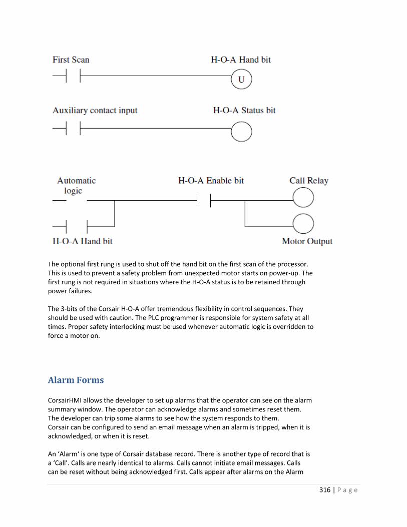
316 | P a g e
The optional first rung is used to shut off the hand bit on the first scan of the processor. This is used to prevent a safety problem from unexpected motor starts on power-up. The first rung is not required in situations where the H-O-A status is to be retained through power failures. The 3-bits of the Corsair H-O-A offer tremendous flexibility in control sequences. They should be used with caution. The PLC programmer is responsible for system safety at all times. Proper safety interlocking must be used whenever automatic logic is overridden to force a motor on.
Alarm Forms CorsairHMI allows the developer to set up alarms that the operator can see on the alarm summary window. The operator can acknowledge alarms and sometimes reset them. The developer can trip some alarms to see how the system responds to them. Corsair can be configured to send an email message when an alarm is tripped, when it is acknowledged, or when it is reset. An ‘Alarm‘ is one type of Corsair database record. There is another type of record that is a ‘Call’. Calls are nearly identical to alarms. Calls cannot initiate email messages. Calls can be reset without being acknowledged first. Calls appear after alarms on the Alarm

317 | P a g e
Summary window. Most references to ‘Alarms’ in the rest of this document also apply to Calls. When an alarm is first tripped it appears flashing on the alarm summary window. Flashing indicates an ‘Unacknowledged’ alarm. When the operator acknowledges it the line on the window stops flashing. When the alarm condition is reset the alarm disappears from the summary window. Alarm Options Some alarms can self-reset when the alarm condition clears. A tank high level alarm may reset itself when the level goes below the high level alarm setpoint. Other alarms may require a reset action by the Corsair operator. A common example is a motor failure alarm that indicates that a motor did not start. A plc may try to start the motor and look for a starter contact to confirm that the motor is running. If the PLC does not get this contact within a short time it would activate the motor failure alarm and shut off the output that runs the motor. In most cases the alarm should stay active until the operator resets the alarm and the PLC tries to start the motor again. The ‘Operator Reset’ Yes/No option on the Corsair alarm record is used by the developer to define how the alarm is going to act. Another alarm option is related to what happens when an alarm has cleared itself before it is acknowledged by the operator. Some alarms may be cleared from the summary page before acknowledgement occurs. Other alarms should stay on the summary page until they are acknowledged to make sure that the operator knows that the alarm occurred. The “Latch’ Yes/No option on the Corsair alarm record is used by the developer to define this behavior for some forms of alarm. Alarm State Bits Each alarm database record has 4 state bits that are kept within the alarm record itself. These bits are designated as follows: Status – Bit 0 – least significant Latch – Bit 1 Acknowledge (‘Ack’) - Bit 2 Special – Bit 3 – most significant The Corsair Alarm Summary window looks at three of these bits – Status, Latch, and Ack. They have predefined meanings to the Corsair program. The fourth Special bit does not have any special significance to Corsair. The Status bit corresponds to the state of the alarm. It is one when the alarm is active and zero when it is not active. A simple high level alarm on a water tank may have a setpoint of 12 feet. When the level is 13 feet the alarm status bit would be ‘On’ (1). When the level is 11 feet the alarm status bit would be ‘Off’ (0). The Ack bit is turned on when the Corsair operator acknowledges the alarm. It is used to indicate that the operator saw the alarm. Some systems may use this bit to silence some sort of audible device like a bell or buzzer. ‘Silencing’ an alarm is not the same thing as ‘Resetting’ an alarm.

318 | P a g e
The Latch bit is used to ‘remember’ that the alarm status bit has been on when the status has been cleared before the alarm is acknowledged. Sequence of Events for Alarm Bits – Non-Latching Alarm Alarm status is set followed by acknowledgement before the status clears: Status Latch Ack 0 0 0 Initial State 1 1 0 Alarm is tripped but not acknowledged 1 1 1 Alarm has been acknowledged 0 1 1 Status Bit is cleared from alarm resetting 0 0 0 Back to initial state Alarm status clears before the alarm is acknowledged: Status Latch Ack 0 0 0 Initial State 1 1 0 Alarm is tripped but not acknowledged 0 1 0 Status Bit is cleared from alarm resetting 0 0 0 Back to initial state Sequence of Events for Alarm Bits – Latching Alarm Alarm status is set followed by acknowledgement before the status clears: Status Latch Ack 0 0 0 Initial State 1 1 0 Alarm is tripped but not acknowledged 1 1 1 Alarm has been acknowledged 0 1 1 Status Bit is cleared from alarm resetting 0 0 0 Back to initial state (This is the same as for a latching alarm) Alarm status clears before the alarm is acknowledged: Status Latch Ack 0 0 0 Initial State 1 1 0 Alarm is tripped but not acknowledged 0 1 0 Status Bit is cleared from alarm resetting 0 1 0 Alarm is waiting for acknowledgement 0 1 1 Alarm has been acknowledged 0 0 0 Back to initial state Alarm Operations Corsair alarm operations include acknowledging the alarm, resetting the alarm, tripping the alarm, and turning the special bits on and off. Alarm Indexes Alarm records that are created under tags use an index value. This value tells where on the tag the alarm data is located. A tag may have a size of 10. Up to 10 alarms with index values from 0 to 9 can be created under this tag. If an alarm has an index value greater than or equal to the tag size the alarm treated as if it has the Memory form. Alarm Forms All alarm records contain all four state bits. The bits get their values in several different

319 | P a g e
ways depending on how the alarm is configured. Corsair alarms can exist in five distinct forms. The forms differ in how the alarm state bits are handled. Some forms are very easy for the Corsair developer to create, some require quite a bit more work. Some forms require more work for the PLC programmer. Alarm Form: Memory Memory alarms are created as free-standing alarm records that are not under a tag. A memory alarm’s status bit can only be controlled as the result of a Corsair program block that is associated with the alarm. The Corsair program handles the Latch, Ack, and Special state bits. The Alarm’s Latch Yes/No option helps to determine how the alarm state bits operate. The alarm index field is not used for this form. Memory alarms are the simplest alarms to develop. They do not require any PLC logic and only very simple Corsair logic. They are the least flexible form of alarm. Alarm Form: 1-Bit PLC For this form a PLC has a tag with the type of 1-Bit Alarm. Alarms can be created under this tag. Each alarm gets a PLC address that is calculated from the PLC address of the tag. Corsair scans PLC memory and places the results into the tag data. It then transfers the tag data into the status state bit of each alarm. The Corsair program handles the Latch, Ack, and Special state bits. The Alarm’s Latch Yes/No option helps to determine how the alarm state bits operate. Alarm Form: 1-Bit Tag For this form a memory tag has the type of 1-Bit Alarm. Alarms can be created under this tag. Corsair does not show any PLC address for the alarm. The Alarm index value is used to determine where each alarm gets it’s data from the parent tag. Corsair transfers the tag data into the alarm status bit of each alarm. The Corsair program handles the Latch, Ack, and Special state bits. The Alarm’s Latch Yes/No option helps to determine how the alarm state bits operate. Alarm Form: 4-Bit PLC For this form a PLC has a tag with a type of 4-Bit Alarm. Alarms can be created under this tag. Each alarm gets a PLC address that is calculated from the PLC address of the tag. Corsair scans PLC memory and places the results into the tag data. It then transfers the tag data into all 4 state bits of the alarm. The Corsair program does not directly determine the values of the 4 state bits since all 4 are read from the PLC. The PLC programmer is responsible for sequencing the bits. The Alarm’s Latch Yes/No option is not significant with this form. Alarm Form: 4-Bit Tag For this form a memory tag has the type of 4-Bit Alarm. Alarms can be created under

320 | P a g e
this tag. Corsair does not show any PLC address for the alarm. The Alarm index value is used to determine where each alarm gets it’s data from the parent tag. Corsair transfers the tag data into all 4 state bits of the alarm. The PLC programmer is responsible for writing Corsair logic to sequence the 4 state bits. This is usually the most complex alarm to implement. The Alarm’s Latch Yes/No option is not significant with this form. Alarm Authority All of the alarm forms except a Memory Alarm have one or more alarms created ‘under’ a tag. Each tag has a field that may be used to associate an authority tag with it. An authority tag is an integer value that determines what the Corsair computer can do with the alarm. If the authority tag has a value of zero the computer can see the alarm and can acknowledge and reset it without a password. If the authority tag has a nonzero value that is less than the size of the password tag a password is required to operate the alarm. If the authority device has a larger value the alarm will not be shown on the computer – all 4 of its bits will be cleared. The authority system can be used to enable and disable groups of hundreds of alarms and calls.
Battery Low Logic The CorsairHMI program has the capability to show if the battery on a data source is low. Battery low
monitoring is simple to develop. The PLC programmer sets up a single bit as an indicator that
CorsairHMI can monitor. The Corsair developer created a tag with the Indicator type that reads the bit.
He then links in into the PLC’s data source record. When the PLC puts a value of one into the bit Corsair
shows that the battery is low. When the PLC puts a value of zero into the bit Corsair shows that the
battery is OK.
Clock Logic CorsairHMI has the capability to monitor and control a time of day clock from a data source. Typically
the data source is a Programmable Logic Controller (PLC). The software provides standard windows that
are used by the operator to set the clock. The PLC programmer must write a small amount of logic to
create a standardized clock interface for Corsair to use. This interface requires a single tag in the Corsair
database. This is an Integer tag with its changeable flag set to ‘Yes’. It is recommended to set its format
to U4.0. The size of the tag should be at least 15 if the Corsair computer is to be able to set the clock. It
can be as low as 7 if Corsair is to read but not set the clock. After the tag is created the developer links it
into the PLC’s data source record. That PLC will now appear on the Corsair clock monitoring screen.
The Clock monitoring tag with a size of 15 corresponds to 15 integer registers in the PLC. Registers [0] to
[6] are used by Corsair to read the clock. Registers [7] to [14] are used by Corsair to set the clock.

321 | P a g e
Register assignment is:
[0] Clock Read Seconds 0-59
[1] Clock Read Minutes 0-59
[2] Clock Read Hours 0-23
[3] Clock Read Day of Week 1-7 1=Sunday 7=Saturday
[4] Clock Read Day of Month 1-31
[5] Clock Read Month 1-12
[6] Clock Read Year
[7] Clock Set Seconds 0-59
[8] Clock Set Minutes 0-59
[9] Clock Set Hour 0-23
[10] Clock Set Day of Week 1-7 1=Sunday 7=Saturday
[11] Clock Set Day of Month 1-31
[12] Clock Set Month 1-12
[13] Clock Set Year
[14] Clock Set Control Bits
The Corsair interface allows setting the Day of Week (Sunday to Saturday) value but many pieces of
equipment calculate the day of the week from the date. They will not allow it to be set.
The PLC programmer is to write code that puts valid clock values into the [0] to [6] elements. This code
does not have to execute on every PLC scan. One quarter (0.25) second is a recommended update rate
for these registers.
The Corsair program sets the clock by writing data into registers [7] through [14] in a single operation.
The [14] register consists of bits that determine what clock items are changed. Corsair can change up to
7 clock items in a single operation by writing a non-zero value to register [14]. The bit assignments are:
Bit 0 – place value 1 – Set Seconds
Bit 1 – place value 2 – Set Minutes
Bit 2 – place value 4 – Set Hours

322 | P a g e
Bit 3 – place value 8 – Set Day of Week
Bit 4 – place value 16 – Set Day of Month
Bit 5 – place value 32 – Set Month
Bit 6 – place value 64 – Set Year
When the PLC program sees a non-zero value in register [14] it is to perform the desired clock set
operations and then place a value of zero into register [14]. It is to ignore values in the [7] to [13]
registers whose corresponding bit in [14] is not set. It is not required for the PLC to zero out [7] to [13]
after a clock set and it is preferable that it does not zero them.
If the PLC sees a nonzero value in register [14] when it first starts scanning its program the correct action
is for it to set 0 into [14] without changing any clock values.
In summary, registers [0] to [6] are set by the PLC and read by CorsairHMI. Registers [7] through [13] are
written by CorsairHMI and read by the PLC. Register [14] is written by CorsairHMI, read by the PLC, and
then reset to zero by the PLC.
The operator clock set window has buttons to open a clock data monitor for each PLC. This window
shows all of the data in the 15 integer registers and enables the PLC programmer to experiment with his
clock logic.

323 | P a g e
The check boxes on the left show which of the 7 clock set control bits are set. These should not stay
checked if the PLC program is running. The buttons can be used to turn on the bits to test clock set
operation,
Shift Indication Logic Manufacturing production data is frequently totalized in shifts. Each production day may consist of 2
12-hour or 3 8-hour shifts. It may consist of 2 10-hour shifts with a 4-hour downtime. Some plants
change their shift schedules seasonally or to adjust for production demands.
A production day seldom starts at 00:00 midnight. Production for December 7th might start at 11:00 PM
on December 6th. It could also start at 7:00 AM on December 7th. Midnight to 7:00 AM on December 7th
may be counted as December 6th production.
The PLCs time of day clock is frequently used to determine shifts. This document describes sample PLC
logic to handle shift determination and production date in a very simple system. It should be adequate
for many purposes.

324 | P a g e
The example logic has 4 setpoints that are entered by the operator using the Corsair interface. The first
setpoint is the time that the date is ‘grabbed’. The other setpoints are the shift 1, 2, and 3 start times.
Usually the date grab time is 1 minute after the Shift 1 start time. Here is a possibility:
Date Grab Time 7.01 (1 minute after 7 AM)
Shift 1 Start Time 7.00 (7 AM)
Shift 2 Start Time 15.00 (3 PM)
Shift 3 Start Time 23.00 (11 PM)
In this example the production day begins at 7AM. At that time the day’s production totals and the
grabbed date are copied to a place in PLC memory that holds historical data. The production totals are
then zeroed. One minute later the displayed production date is changed to the new day.
Here’s another possibility:
Date Grab Time 0.00 (Midnight)
Shift 1 Start Time 23.00 (11 PM)
Shift 2 Start Time 7.00 (7 AM)
Shift 3 Start Time 15.00 (3 PM)
The production day begins at 11:00 PM on the previous clock day. That’s the time when historical data
is saved and the totals are zeroed for the new day. The new date is grabbed an hour later at midnight.
This system will totalize production correctly but it will not show the correction production date on the
interface during the 11 PM to midnight hour. This is typically not a problem.
The PLC frequently needs shift production Boolean flags for its totalization. They can also be used to
show the current shift on the interface.
This suggested code is only a starting point for writing PLC shift logic.
Clock_Time := Clock_Hour * 100 + Clock_Minute ;
Clock_Date := Clock_Month * 100 + Clock_Day_of_Month ;
IF Clock_Time = Grab_Date_Setpoint THEN
Grabbed_Date := Clock_Date ;
END_IF;

325 | P a g e
----+------ Clock_Time >= Shift_1_Start ------ Clock_Time < Shift_2_Start------+---( )- Shift 1
! !
+----- Shift_2_Start < Shift_1_Start -----+-----Clock_Time < Shift_2_Start -------+
! !
+---- Clock_Time >= Shift_1_Start ------+
----+------ Clock_Time >= Shift_2_Start ------ Clock_Time < Shift_3_Start------+---( )- Shift 2
! !
+----- Shift_3_Start < Shift_2_Start -----+-----Clock_Time < Shift_3_Start -------+
! !
+---- Clock_Time >= Shift_2_Start ------+
----+------ Clock_Time >= Shift_3_Start ------ Clock_Time < Shift_1_Start------+---( )- Shift 3
! !
+----- Shift_1_Start < Shift_3_Start -----+-----Clock_Time < Shift_1_Start -------+
! !
+---- Clock_Time >= Shift_3_Start ------+
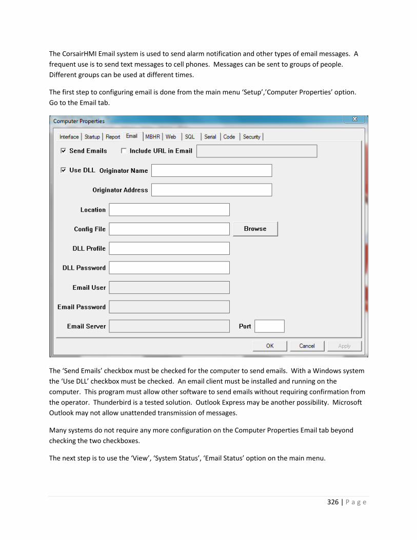
326 | P a g e
The CorsairHMI Email system is used to send alarm notification and other types of email messages. A
frequent use is to send text messages to cell phones. Messages can be sent to groups of people.
Different groups can be used at different times.
The first step to configuring email is done from the main menu ‘Setup’,’Computer Properties’ option.
Go to the Email tab.
The ‘Send Emails’ checkbox must be checked for the computer to send emails. With a Windows system
the ‘Use DLL’ checkbox must be checked. An email client must be installed and running on the
computer. This program must allow other software to send emails without requiring confirmation from
the operator. Thunderbird is a tested solution. Outlook Express may be another possibility. Microsoft
Outlook may not allow unattended transmission of messages.
Many systems do not require any more configuration on the Computer Properties Email tab beyond
checking the two checkboxes.
The next step is to use the ‘View’, ‘System Status’, ‘Email Status’ option on the main menu.
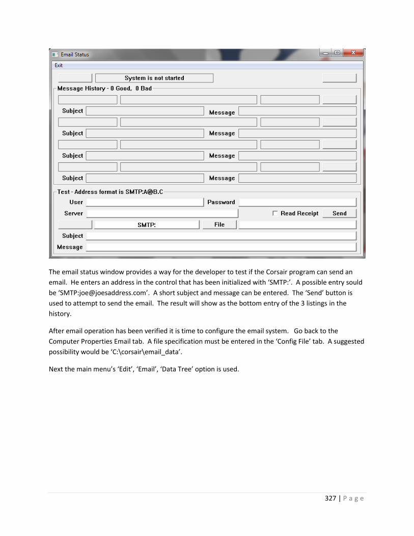
327 | P a g e
The email status window provides a way for the developer to test if the Corsair program can send an
email. He enters an address in the control that has been initialized with ‘SMTP:’. A possible entry sould
be ‘SMTP:[email protected]’. A short subject and message can be entered. The ‘Send’ button is
used to attempt to send the email. The result will show as the bottom entry of the 3 listings in the
history.
After email operation has been verified it is time to configure the email system. Go back to the
Computer Properties Email tab. A file specification must be entered in the ‘Config File’ tab. A suggested
possibility would be ‘C:\corsair\email_data’.
Next the main menu’s ‘Edit’, ‘Email’, ‘Data Tree’ option is used.

328 | P a g e
The email data window has a tree control on the left side that is used to show all of the email data in a
tree-structured format. The developer can click on a tree item and see a description of it on the right
side of the window.
There are 4 header items on the root of the email tree. They are:
Address Families
Contacts
Contact Groups
Send Groups
Data items can be entered under each of these headings. Each type of data has different options. There
are some common options for different data types.
The Note Option
The developer can enter a single-line note into each data item. This can be a description of the item. It
does not appear anywhere in any email message. It is only shown on the email data window and on
printouts that summarize email configuration.
The Temporary Marker
Each data record that the developer enters has a Temporary checkbox associated with it. This box may
be checked as a reminder that the record is eventually to be deleted or changed.

329 | P a g e
An on-call operator may lose his cell phone and need to use a different cell phone until he gets a
replacement. The Corsair developer would change the address to his cell phone and then check the
Temporary marker to show that it will need to be changed.
The Enable Checkbox
Each item has a checkbox that is checked by default. It enables the item. If it is not checked the item is
not active. This Enable status can be changed dynamically from a Corsair tag. If that option is used a
nonzero tag index must be entered.
Transmission Type
A Transmission type is a method to send data. Currently the only supported transmission type is ‘email’.
Other types of transmission may be added in the future. Cell phone text message use the email
transmission type.
Address Family List
An address family represents a group of addresses that all use the same transmission type. The
developer enters the following items:
Name
Note
Radio Buttons – Type: Email, Future
SMTP Prefix Check Box
Temporary Check Box
Enable Check Box with Tag Index Entry
The SMTP prefix is checked on by default. The Windows email system requires this prefix in front of all
addresses. If the option is checked the computer puts the prefix in front of each address automatically.
The developer does not have to enter the prefix on each individual address.
Contact List
The Contact List is a database of people that can get emails. It includes the following items:
Name with Tag Index Entry
Note
Temporary Check Box
Enable Check Box with Tag Index Entry

330 | P a g e
The developer can enter one or more addresses under each contact.
Address
The Address is entered under a contact. Each contact can have multiple addresses. An address includes
the following items:
Name
Address Family Link
Note
Address String with Tag Index Entry
Radio Buttons - Normal, Always To, Always CC, Always BCC
Temporary Check Box
Enable Check Box with Tag Index Entry
Contact Group
A contact group is a collection of addresses. Each contact group includes the following items:
Name
Note
All Addresses Check Box
Temporary Check Box
Enable Check Box with Tag Index Entry
The developer can link multiple addresses under each Contact Group.
Contact Group Address Link
A contact group address link hooks an address to the contact group. It includes the following items:
Address Link
Note
Radio Buttons - To, CC, BCC
Temporary Check Box
Enable Check Box with Tag Index Entry

331 | P a g e
Send Group
A send group is a collection of Contact Groups. Each send group includes the following items:
Name
Note
Send Group Key Number
All Contact Groups Check Box
Temporary Check Box
Enable Check Box with Tag Index Entry
Send Groups are hooked to Corsair alarms through a nonzero key number that is assigned by the Corsair
developer. Each send group should have a different key number.
The developer can link multiple Contact Groups under each Send Group.
Send Group Contact Group Link
A Send Group Contact Group link hooks a Contact Group to the Send Group. It includes the following
items:
Contact Group Link
Note
Temporary Check Box
Enable Check Box with Tag Index Entry
A Minimal System
There is one address family named ‘Cell Phones’. There is one Contact in the Contact list with one
address that is linked to the Cell Phones family. There is one Contact Group. ‘All Addresses’ is checked.
There is no need to link any Addresses to the Contact Group. There is one Send Group with key number
one. ‘All Contact Groups’ is checked on it. There is no need to link any Contact Groups to the Send
Group.
Tag Connections to the Email System
The Corsair program can control the email system through tags that use the Email Control driver.
To be continued
Email Item Active Indications

332 | P a g e
Many email tree items have an ‘Enable’ checkbox. It is checked by default. The operator can turn off
the checkmark to deactivate the item. If a nonzero tag index is entered for the Enable the Enable can be
checked or unchecked dynamically from tag data.
The email development window includes an indicator on each item to show if it is active. If Enable is not
checked for the item it is not active. There are additional rules depending on the type of the item.
An Address is not active unless it is linked to an active Address Family.
A Contact is not active if it does not have at least one active Address.
A Contact Group Address Link is not active unless it is linked to an active Address.
For a Contract Group to be active is must have at least one active Address Link or
‘All Addresses’ is checked and an active Address exists in the tree.
A Send Group Contact Group link is not active unless it is linked to an active Contact Group.
For a Send Group to be active is must have at least one active Contact Group Link or
‘All Contact Groups’ is checked and an active Contact Group exists in the tree or
an active Address has an ‘Always’ option selected.
Email Sending Rules
When an alarm is tripped, ackked, or reset Corsair first looks to see if ‘Send Emails’ is checked on the
Computer Properties Email tab.
It then looks to see what send groups have been attached to that action of the alarm. Up to 3 groups
can be assigned to trip, ack, and reset.

333 | P a g e
If all three group numbers are zero no email is sent. Nonzero group numbers are checked against the
Send Groups data base. A group must have a matching key number and be active for the group to be
sent.
CorsairHMI Menus The CorsairHMI program contain a menu system that can be used to access multiple Corsair interface computers over the web. It is shown to the computer operator as to a web browser as a list of links in a tree-structured format. This structure may look like this:
D
I
H
A

334 | P a g e
A, B, and C are ‘root’ items at the highest level on the tree. A is a ’parent’ to D. H is a ‘child’ of D. F and G are ‘siblings’ and are ‘children’ of B. Each item in the list may have an icon to the left of the text. The icon may change as conditions in the system change. The icon on a parent may change to reflect an alarm condition on one of its children. The text label may also change dynamically. Corsair menus are made of six types of links:
1. Model Links 2. Folder Links 3. Web Links 4. Direct Machine Links 5. Automatic Machine Links 6. Configured Machine Links
A ‘model link’ corresponds to a model file running on a CorsairHMI computer. One instance of the Corsair program can use up to 100 models. The ACME company makes toys and tractors in several plants around the world. It has toy plants in New York, Charlotte, Los Angeles, and San Diego. Each of these plants has Corsair plant wide interface using a single model file. Each of these models has been copied to a North American Toys headquarters computer. Headquarters talks to the plant computer using the high speed MBHR protocol. Each part of the plant is isolated with a streaming serial system for data security. The headquarters menu initially looks like this: New York (Model Link) Charlotte (Model Link) Los Angeles (Model Link) San Diego (Model Link) Note that all four plants show up as siblings on the root of the menu tree. An operator siting at the headquarters computer can click on any item to view it interface data. If someone is browsing the headquarters computer over the web he sees the same menu and can do the same thing.
B
C
E
F
G

335 | P a g e
Model links are always at the end of a branch of a tree. They cannot have any children. The following construction is invalid:
In this example, each model is ‘resident’ on the headquarters computer. When the operator clicks on the model he views the interface through the Corsair program and not with a web browser. Resident models cannot be placed under machine links on the menu. They can be placed under Folder Links. A Folder model can be developed on the headquarters machine to display summary data totalized from the other four models. Some folder links can provide organization.
A (Model Link)
B (Web Link)
East Coast (Folder Link)
West Coast (Folder List)
New York (Model Link)
Charlotte (Model Link)
Los Angeles (Model Link)
San Diego (Model Link)
Summary (Model Link)
Company Web Site (Model Link)

336 | P a g e
Now the models are organized under folders. A model cannot have children but a Folder can. A web link has been added to access the company’s web site. Web links cannot have children. When the headquarters operator clicks on the web link, his browser opens to that address. The same thing happens when a remote browser clicks on it. Now the company adds a computer for a menu structure for its western hemisphere operators. It produces this new structure: The North American Toys machine link is configured to point to the North American Toys headquarters machine. This machine link will collect all of its child menu data automatically from the downstream computer. Next the company adds a computer for a menu structure for its worldwide operations. It creates this menu structure:
North America (Folder Link)
Tractors (Automatic Machine Link)
Toys (Automatic Machine Link)
Toys (Automatic Machine Link)
Tractors (Automatic Machine Link)
Company Web Site (Web Link)
Western (Automatic Machine Link)
Eastern (Automatic Machine Link)
South America (Folder Link)
International (Folder Link)

337 | P a g e
Each of these machines links will automatically collect its child menu data. When all of these computers have run for some period of time if someone browses the International computer he will see the following menu structure:
International (Folder Link)
Western (Machine Link)
North America (Folder Link)
Toys (Automatic Machine Link)
East Coast (Folder Link)
New York (Model Link)

338 | P a g e
Note that the model links and web link items cannot have child items. When a browser opens a web link it gets the URL address from the data that has been enlarged for that link. When the browser opens up a model link it browses into from Corsair computer whose IP address is entered into the nearest upstream machine link. Folder links cannot open up web pages by clicking on them. When a menu system is complete each folder link will have at least one child. If an operator is at a Corsair computer and he clicks on a Direct Machine Link the computer does the same action as if the ‘Run’ button on the overview page is clicked. If he is browsing the menu and he clicks on a Direct Machine Link the browser opens up a window on the Corsair Computer. It may appear that this is equivalent to a web link but there are significant differences. A machine link is specified with a static IP address. A web link may be specified with a domain name. The Direct Machine Link may be passed Corsair credential information. Credential information is not passed to web link. A Direct Machine Link will usually not have any children although children are permitted. An Automatic Machine Link does not open a window when it is clicked on. The computer determines what child items belong to the Automatic Machine Link by reading them through the internet. Items may appear or disappear as things change downstream.
Eastern (Machine Link)
Company Web Site (Web Link)
South America (Folder Link)
Toys (Automatic Machine Link)
Tractors (Automatic Machine Link)
Tractors (Automatic Machine Link)
West Coast (Folder Link)
Company Web Site (Web Link)
Summary (Model Link)
Charlotte (Model Link)
Los Angeles (Model Link)
San Diego (Model Link)

339 | P a g e
A Configured Machine Link does not open a window when it is clicked on. The Corsair developer must manually enter the child items for the link. Model Link Parameters The first parameter of a Model Link is the model number that it appears under in the Corsair computer properties. This could range from 1 to 100. The test for the label is also entered. If it is left blank the nickname from the Corsair model link is used. If it is also blank the label ‘Model #’ is used. Web Link Parameters The URL that is required by the browser must be entered. The label for the menu item can be entered. If the label is left blank the URL is used for the label. Folder Link Parameters The label for the menu item can be entered. If it is left blank the label ‘Folder-#Items’ will be used. Common Machine Link Parameters All Machine Links must have the IP address of the downstream machine entered. This must be a known static address. They must have a TCP port address of that machine entered. If the port address is left at zero, the default value of 80 is assumed. All machine links can have the text label for the link entered. Direct Machine Link Parameters Automatic Machine Link Parameters
Any menu item that is under an Automatic Machine Link cannot be edited by the Corsair developer. Children of Automatic links cannot be inserted, deleted, or edited. This is because this information is to come automatically through communications. Edits can be made by changing the link to a Configured type. Configured Machine Link Parameters
Menu Configuration
A CorsairHMI program is configured with two menu data structures. One is the ‘web’ menu that is sent
over the web to a browser. The other is the local menu that is viewed on the Corsair computer monitor.
Separate file menus can be entered for each of the two menus. In many Systems the two menus are
identical and the same file name is used for both. The web tab on the Computer Properties is used for
enabling the menus. It features separate check boxes to enable web and local menus and edit boxes to
enter file names. A ‘Pass Upstream’ check box is included for the web menu. Another Corsair computer
may have an Automatic machine link that points to the machine at its menu. It will attempt to hook into
this computer to obtain menu item information. The ‘pass upstream’ option must be checked for
information to be passed. Only the web menu can be passed upstream, never the local. Automatic
machine links can be placed in both web and local menus. In both cases menu data can be collected
from a downstream machine but always from its web menu.

340 | P a g e
The Login System
To be continued
MBHR Serial Hosting Normal MBHR communications occur between a host computer and multiple remote computers over
Ethernet. There is a special hosting option that allows the host computer to also act as a Modbus slave
device over a serial connection. This makes it possible for another computer to read and write tag data
by treating the host computer as if it is a Modbus-compatible PLC. This is using the Modbus RTU
protocol and not the Modbus ASCII protocol.
Web Hosting The CorsairHMI developer manual describes how to set up computer properties for web hosting. This is
the first step. The next step is to use the ‘View’ ’System Status’ ’Web Host Status’ menu option to open
a window that monitors web hosting.

341 | P a g e
The status line shows if Web hosting has started up successfully. Sometimes it displays a message like
‘OS Err 5 Access is denied’. This frequently means that the Corsair program needs to be ‘Run as
Administrator’. This is an option in the properties of the shortcut that starts the program. After it is
selected the computer may display a box asking the operator if the program should be allowed to make
changes. Unattended Corsair computers will have to have this notification shut off so it does not cause
a problem when restarting after a power failure.
Once hosting has started it is a good idea to browse the Corsair computer from itself. Start a browser
and enter the ‘127.0.0.1’ loopback address. Verify that you can see the Corsair program. If the
computer cannot see itself other computers will not be able to see it.
The next step is to determine what IP address on the local network must be browsed to see the Corsair
computer. The network adapter must have a ‘static’ IP address that is guaranteed not to change even if
the power is cycled. An automatically assigned IP address is not guaranteed to continue working. The
static address may be something like 192.168.1.12. Open a browser on another computer on the local
network and type in that address to verify local operation. If this does not work Windows Firewall
settings on the Corsair computer may need to be changed.
The next step may be to link the Corsair computer to the Internet via a router. The router must have a
public static IP address on the Internet. This address will be different than the IP address of the Corsair
computer on the local network. It is provided by the Internet Service Provider who may charge an extra
fee for it.

342 | P a g e
For temporary sales demonstrations a ‘What is my IP’ browser enquiry would show the Internet IP
address for the router at that minute. This may be used in place of a public static IP for a short period of
time but it is unsuitable for long-term use.
The next step is to open up the configuration of the router. This requires the user name and password
for the router. Typically two things need to be configured. The first is to make sure that the local static
IP address of the Corsair computer is not in the pool of IP addresses that the router is automatically
assigning to local computers. It is highly recommended that this step is taken rather than trust the
router to keep things the same.
The next step is to set up port forwarding from the Internet static IP to the local IP of the Corsair
computer. This is typically done for port 80. Your network administrator may require the use of a
different port number. This may involve changing the Host URL entry on the Computer Properties Web
tab.
This document cannot cover everything that may be encountered when setting up Corsair web hosting.
A qualified network administrator may be needed to work through addressing and security issues. He
will definitely be needed if a VLAN is required.
The Event Database Corsair utilizes a predefined format for the columns in an Event logging SQL database. This utilizes 16
columns. The SQL Expert can be used to format a database for these columns.
The type of the columns may vary with the chosen database server. Corsair presently supports 3 types
of database server:
Microsoft SQL Server (Including Express)
Old Microsoft SQL Server
MySQL
The Corsair Manual has a printout in the Reference section that details recommended field types for
each type of database server. The following list shows general characteristics of the fields. Consult the
manual printout for more details.
Column #1 of 16 EventTime
This is the time that the event happened. It can come from the interface computer or from the SQL
computer. This column does not allow NULL (empty) data.
Column #2 of 16 EventType
This is the label for the type of event with a maximum of 16 characters. This column does not allow
NULL data.

343 | P a g e
Column #3 of 16 ItemName
This is the tag name of the data item that is involved. It must allow NULL data.
Column #4 of 16 ItemIndex
This is the index of the tag. It corresponds to an array element. Values range from 0 to the size fo the
tag minus 1. The column must allow NULL data.
Column #5 of 16 ItemDescription
A description that is asssociated with the tag. NULL data must be allowed.
Column #6 of 16 ItemArea
This is where the event happened. It is taken from the area of the ItemName record. If it has no area it
is taken from the area of the Node record. NULL data must be allowed.
Column #7 of 16 Node
This is what computer generated the event. It can be from a record in the program or from the
computer’s operating system name. NULL data is not allowed.
Column #8 of 16 PreValue
The value before the change. NULL data must be allowed.
Column #9 of 16 PostValue
The value after the change. NULL data must be allowed.
Column #10 of 16 Operator
This is the name of the logged-in operator. It can be from the program’s log-in system or from the
operating system’s user name. NULL data is not allowed.
Column #11 of 16 Priority
This is the priority of the event. Higher numbers are more important. NULL data must be allowed.
Column #12 of 16 Tag1Value
The value of a tag at the time of the event. NULL data must be allowed.
Column #13 of 16 Tag2Value
The value of a tag at the time of the event. NULL data must be allowed.
Column #14 of 16 Tag3Value

344 | P a g e
The value of a tag at the time of the event. NULL data must be allowed.
Column #15 of 16 Tag4Value
The value of a tag at the time of the event. NULL data must be allowed.
Column #16 of 16 Comment
This is an operator-entered multiple-line comment. NULL data must be allowed.
Report Forms The current event logging system used by the Corsair program is focused on discrete events in time - like
the tripping of an alarm, an interface starting, an operator entering a note, and so on. It uses a
predefined table column format that is not changeable.
Analog data logging by the Corsair program is typically into .CSV text files. Each line of the CSV contains
fields that define the date and time of the entry. The file names can contain calendar and clock
dependent labeling. Corsair can view this data in a graphic plotting format without the use of other
software tools. The Corsair Turn-Back-Time system also uses this data. It can be directly loaded into
Excel or other tools that can utilize CSV files.
The event logging system can be used to log analog values into an SQL database with some limitations.
There are four columns named 'Tag 1' through 'Tag 4'. These columns are text fields that can be used
for analog data. An alarm can be defined that trips at periodic intervals to log these four values. The
intervals can change dynamically so that samples are generated more often when values are out of
range. Other alarms can be defined that send four different values into the same SQL table. The values
from these events can be viewed in a row-column format using the Corsair program or viewed with
other SQL viewing tools. Corsair has some capability to print this data. It does not currently have any
ability to plot it. Note that the same data can be sent to both a CSV and to an SQL database. Corsair has
been tested with two different versions of Microsoft SQL Server and with MySQL.
Alarms that are used to trip SQL records can be prevented from appearing on the Corsair Alarm
Summary window.
There is a special totalization feature that works with the Corsair SQL event system. Suppose that a
water plant has influent and effluent meters feeding into a PLC that is integrating flow. Corsair can
generate signals for each meter that occur every time 1000 gallons passes throught the meter. Each
time one of these signals is tripped a record is written to the SQL database. In each of these records the
'Tag 1' column contains the value '1000.0'. Corsair can print summary reports and generate CSV files for
flow totalization based upon time intervals. It does this by adding up the 'Tag 1' values for the records
that satisfy its SQL filter settings. Reports showing total flow from midnight to midnight for every day
for the past 3 months are possible. Reports can also show counts of events.

345 | P a g e
Understanding the Modbus Drivers CorsairHMI offers several types of Modbus drivers for specific purposes. The first distinction that must
be drawn is if the computer is to communicate through an Ethernet port or through a serial port. This
determines if an Ethernet or Serial driver is needed. Sometimes the computer talks through Ethernet to
get to an external Modbus Ethernet to Serial converter. An Ethernet driver is needed for this purpose.
If the computer uses a serial port to get to a Modbus device a serial driver is needed. The next
distinction that must be made is what type of serial protocol the device uses. Modbus serial comes in
two variants – RTU and ASCII. They require different drivers. Ethernet drivers do not have the RTU vs
ASCII distinction.
Continue ..
Custom Help Documents
Stuff about custom help documents
Mobile Equipment Tracking
The CorsairHMI program can receive data from NMEA protocol-compliant devices like GPS receivers
over a serial port. These devices transmit data using distinct sentences. There are several standard
sentence types that are used to send latitude, longitude, speed, bearing, and time information. Corsair
only responds to a limited number of sentence types. The Sentence List printout is used to see what
features your version of Corsair is using from each sentence type. This is important when you verify that
the Corsair program can work with your equipment.
Wiring
The GPS equipment is typically wired to the Corsair computer through a standard RS-232 serial port.
The Corsair GPS driver only receives data from the GPS. It never transmits to the GPS. In many cases it
may be desirable to not hook up the data line that transmits from the computer to the GPS. This

346 | P a g e
eliminates the possibility of the Corsair Integrator being falsely accused of sending data to the GPS to
‘hack into’ a navigation system. If the GPS is critical it is highly recommended to put a serial port optical
isolator on the line so that electrical disturbances on the computer or the GPS will not propagate to the
other system.
It may be desirable to have a bidirectional cable for start-up purposes if GPS set-up software is being
used and then switching to a unidirectional cable for Corsair operation.
Data Format
Internally Corsair latitude and longitude values are kept in signed 64-bit integer values that represent
hundred thousandths of a degree. A value of 3000000 means 30 degrees. North latitude is positive.
South latitude is negative. East longitude is positive. West longitude is negative.
Latitude and longitude values are shown to the operator and entered in a text format. The text format
is:
Latitude N (space) # D (space) ##.### M
Longitude E (space) # D (space) ##.### M
The Latitude prefix is N or S for North or South. Longitude is E or W for East or West. The number of
degrees is a variable width number with no leading zero padding. It can be 0-90 for latitude and 0-180
for longitude.
Minutes will only show if they are nonzero. The minutes value is one or two characters varying from 0
to 59. Decimal portions of a minute will only show if they are nonzero with a variable width up to 4
places.
The text formal displays up to 4 decimal places on the minutes. The internal 64-bit integer actually
holds to 5 decimal places which are rounded to 4 for the text display.
Valid strings include:
N (space) 28 D
E (space) 28 D (space) 23 M
S (space) 12 D (space) 59.56 M
E (space) 153 D (space) 12.4567 M
Development
The first step of GPS system development is to set the properties of the serial port under the
Setup/Comms Port Properties menu option. The NMEA standard calls for 4800 baud communication

347 | P a g e
with no parity, 8 data bits, and 1 stop bit. This should be the first combination that is tried if the
documentation on the equipment does not list something else.
The next step is to create a driver record in the database. Pick Edit/ Data/ Drivers and press F4 to create
a driver. Go to the ID column and press F2 to enter a name for the driver. Go to the type column and
press F2 followed by F1 to get the driver type selector. Select the “GPS – NMEA Compatible GPS Serial”
driver type. Go to the Port column and press F2 to enter the proper serial port number. The range of
serial ports is from 1 to 10.
While still on the driver record, press the F6 key to go to single record editing of the driver. Use the
About button to print a short printout describing details of the NMEA driver.
Click on the PLC (Data Source) button to edit the PLC records that are on the driver. Press F4 to create a
Data Source for the GPS. Go to the ‘Real’ column and press F2 to enter Y for Yes.
While still on the data source record, press the F6 key to go to single record editing of the data source.
There is a button labeled ‘Res Addr’ for Reserved Addresses. It is used to automatically create tags using
the proper reserved address labels for the driver. Click on it and pick OK. The Tags button should now
show that some tags are present. Click on it to see the tags that have been created. Note that the name
of the tag is the same as the Start Address. The Start Address labels must not be changed. The Tag
names can be changed if desired. The driver’s About printout gives some information as to the function
of each tag.
Note that the GPS driver can only deal with a single stream of NMEA compatible data on a single serial
port. A second GPS hooked to a second serial port would require a separate driver record. External
sentence combiner hardware may be used to combine data from two pieces of equipment like a GPS
and a depth finder into a single serial line. The Corsair program would treat this data like it comes from
a single source.
Be sure to save the Corsair application file when the development is completed.
Startup
The next step is to turn on the GPS equipment and click on the Interface checkbox to start Corsair’s
interface operation. Use the Tools/ PLC/ Registers menu option – select the GPS PLC if there is more
than one option – and the GPS status window appears. The GPS Online checkbox should be checked. It
is a display-only checkbox – the operator cannot click on it. Some received sentences should appear.
Corsair will show a count of how many sentences of each type it has received and how many unknown
sentences it has received. There is a button to zero these counts if desired. Frequently unknown
sentences are not a problem since manufacturers send proprietary sentences for their equipment that
Corsair can ignore.
The GPS Status window may show sentence types that Corsair recognizes as sentences but Corsair does
not use any of the data from that type. It may only use part of the data from other sentence types. You
may submit requests to CorsairHMI for additional sentence capabilities to be added to the driver.

348 | P a g e
Unknown Sentence Types
If you want to see what the GPS is sending for the unknown sentence types you can view them with the
Corsair Comms Trace window. Select the Tools/ Comms Trace menu option. Enter the proper serial
port number (1-10) in the edit box to the right of the Port radio button. Select the Port radio button.
Click on the start button on the bottom of the window. Characters should start to fill the screen. After a
short time click on the Pause button. The incoming characters are separated into sentences by header
notes as you scroll through the data. For recognized sentence types the header will say “GPS Sentence –
Count of ##”. Unknown types will have a different header showing that Corsair cannot classify the
sentence.
Sentence List
The Corsair program can print an informative list of sentence data that may assist the developer in
understanding what his GPS is doing. Select File/ Print/ Application Manual. Select the desired printer.
From the initial ‘Printing’ tab click on the Nothing button. Pick the Reference tab and check the GPS
Sentences option. Corsair will tell you the page count. Click on OK to make the printout.
Corsair lists several sentence prefixes and portions of prefixes on the printout for sentences that it does
not use. The purpose of the printout is to give the Corsair developer a starting point for understanding
the sentences that he is seeing from his equipment and what Corsair is using them for.
NMEA standard sentences begin with a 2-character code defining the type of equipment. This is
typically GP for GPS equipment. The next three letters determine the type of sentence – like RMC for a
complete sentence prefix of GPRMC.
Vendor proprietary sentence prefixes begin with P followed by a three-character code for the vendor
followed by additional information. A prefix that begins with PGRM is proprietary to Garmin. A prefix
that begins with PMOT is proprietary to Motorola.
Corsair Mobile Equipment Tracking
When the Corsair program is used for a Mobile Equipment Tracking (MET) application it is common to
want the location of the equipment to be translated to an English language text string. Sometimes the
piece of mobile equipment has a GPS, a slave Corsair computer, and a data radio on it. The slave
computer uses the data radio to send latitude and longitude coordinates to a master Corsair computer.
The master computer could name what area the piece of equipment is currently in. An icon
representing the current position of the equipment could move around the screen as the equipment
drives around the site.
The Corsair program has two specialized function blocks that are used to work with GPS coordinate
information. These blocks are named ‘GPS Markers’ and ‘GPS Areas’
The GPS Markers Block

349 | P a g e
Corsair GPS markers are single-point locations that are defined by their latitude and longitude
coordinates. The block is a subprogram that is used to calculate how which marker is closest to the
current position of the equipment.
The GPS Areas Block
Corsair GPS Areas are defined by the latitude and longitude coordinates of 4 points that form a 4-sided
polygon. The sides of the polygon do not have to be at right angles – it does not have to be a rectangle.
The block is a subprogram that is used to calculate which area contains the current position of the
equipment.
Features Common to Both Blocks
Both the GPS Markers and GPS Areas blocks have the ability to convert GPS latitude and longitude
coordinates to screen pixel positions. A single block can do this calculation for several screens. The
developer may desire to have one screen that is an overview of a city and 4 more detailed screens that
correspond to quadrants of that city. The block would have to do pixel calculations for 5 different
screens. Systems can be developed that use several Markers or Areas blocks to show several pieces of
equipment on the screens at the same time. Each block can use the same Marker or Area data but
different GPS coordinates for the different pieces of equipment.
The Modbus Memory Map File
A recommended place to keep the Marker or Area setup data is in a Modbus Memory Map file. This is a
disk file that the Corsair developer can treat as if it is a Modbus-compatible PLC. Tag data can be read
from and written to the file without the developer having to worry about any Load or Save operation.
Pick Edit/ Data/ Driver and press F4 to create a driver record. F2 on the ID column and name it ‘Memory
Map Driver’. Go to the Type column and press F2, F1 to get the driver type selector. Pick ‘MBMM –
Modbus Memory Map’ for the type of the driver.
Go to the Data Sources (PLCs) column and press Z to Zoom. Press F4 to create a data source. Go to the
ID column and F2 to enter the name ‘Block Setup Data Memory Map’.
While still on the ID column, press Z to zoom. This opens up the Special Setup window for the Data
Source. Arrow up and down and press F2 to edit the fields. Here are suggestions:
File Name c:\corsair\mbmm
4X Register Count 10000
Create File if not existing Yes
File is Shared No
Periodic Refresh Time (0 to disable) 0s

350 | P a g e
Block Parameters and Tag Names
The GPS Markers and GPS Areas blocks have similar parameters. The tag names that are mentioned in
this document are only recommendations. The Corsair developer is free to choose other names. Tag
types and formats should be followed exactly.
The first thing that the developer has to do is determine if he wants to use the GPS Markers or the GPS
Areas block. The tag recommendations in the rest of this block will use the term ‘Marker’. If the Areas
block is chosen the developer is encouraged to substitute the term ‘Area’.
The next thing to do is determine how many markers or areas the system will use. This document will
use 100 for its example. The next decision is how many screens the block will have to perform pixel
calculations for. This example will be for 5 screens.
The first group of 5 tags that need to be entered will be block setup data that is a part of the Modbus
memory map data source. Click on Edit/ Data/ Data Sources and go to the one named ‘Block Setup Data
Memory Map’. Go to the Tags column and press Z to zoom.
Press F4 5 times to create 5 tags on the memory map.
Here are the parameters for the 5 tags:
Tag: Marker Latitude Table
Type: 64-bit integer
Format: Latitude
Changeable: Yes
Size: 100 if markers, 400 if areas
Tag: Marker Longitude Table
Type: 64-bit integer
Format: Longitude
Changeable: Yes
Size: 100 if markers, 400 if areas
Tag: Screen Latitude Table
Type: 64-bit integer
Format: Latitude
Changeable: Yes

351 | P a g e
Size: 10 (2 times the number of screens)
Tag: Screen Longitude Table
Type: 64-bit integer
Format: Longitude
Changeable: Yes
Size: 10 (2 times the number of screens)
Tag: Marker Name Strings
Type: String
Length: 20 (or longer if you wish)
Changeable: Yes
Size: 101 (The number of Markers or Areas plus 1)
Types can be entered by going to the type column and pressing F2, F1, to get the Type Selector.
Formats can be entered by going to the format column and pressing F2,F1 to get the Format Selector.
Latitude and Longitude are considered to be special formats – select the Special radio button on the
format selector and they can be selected.
Go up to the first tag on the memory map – the Marker Latitude Table. Go to the Start Address column
and F2 to enter a starting Modbus address of 400001. Corsair will show you a Modbus End address for
the tag (either 400400 or 401600). Arrow down one record to the start address of the next tag and
press F2 to enter the next available Modbus register (either 400401 or 401601). Continue until you have
Modbus register addresses for all 5 tags. Examine the end address for the last tag. If it is greater than
410000 you will have to adjust the 4X register count on the ‘Block Setup Data Memory Map’ data
source. It is recommended that the count should be slightly larger than the last register. The leading ‘4’
in the address is not taken into account for this size. As an example:
Last Address: 400980 Data Source 4X Register Count: 1000 or more
Last Address: 420500 Data Source 4X Register Count: 20600 or more
Excessively high 4X register counts waste memory and disk space and slow the system down.
Be sure to save the application file after these tags are created.
The next group of tags that must be created are memory tags. Make sure that the Interface check box is
off so that the interface is not running. Click on Edit/ Data/ Tags. Arrow to the top of the tag table.
Press F4 13 times if you are using markers or 12 times if you are using areas to create 13 or 12 tags.

352 | P a g e
Look at the column labeled Data Source (PLC). It should have two question marks in it for each of the
tags that you just created. If it does not, enter ‘??’ into this column.
The tags should be as follows:
Tag: Current Marker Index
Type: Integer
Format: U5.0
Changeable: Yes
Size: 1
Tag: Returned Pixel Positions
Type: Double Int
Format: -5.0
Changeable: Yes
Size: 10 (2 times the number of screens)
Tag: Screen 1 GPS Pixel X
Type: Double Int
Format: -5.0
Changeable: Yes
Size: 1
Tag: Screen 1 GPS Pixel Y
Type: Double Int
Format: -5.0
Changeable: Yes
Size: 1
The following tags have identical fields to the ‘Screen 1 GPS Pixel X’ tag.
Tag: Screen 2 GPS Pixel X
Tag: Screen 2 GPS Pixel Y
353 | P a g e
Tag: Screen 3 GPS Pixel X
Tag: Screen 3 GPS Pixel Y
Tag: Screen 4 GPS Pixel X
Tag: Screen 4 GPS Pixel Y
Tag: Screen 5 GPS Pixel X
Tag: Screen 5 GPS Pixel Y
For a marker system only, the last tag is:
Tag: Distance to Marker
Type: Double Float
Format: -5.2
Changeable: Yes
Size: 1
Be sure to save the application file after these tags are created.
Arrow up to the Current Marker Index record and press F6 to do to Single Record Editing mode. Click on
‘Block’ and pick ‘GPS Areas’ or ‘GPS Markers’ as desired. Click on Accept to lock in the block.
Click on Parameters to set up the block parameters. Parameters should be set as follows:
PA:
Tag? No
Tag or Constant: On
PB:
Tag?: Yes
Tag or Constant: Latitude (from the GPS)
PC:
Tag?: Yes
Tag or Constant: Longitude ( from the GPS)
PD:

354 | P a g e
Tag?: Yes
Tag or Constant: Marker Latitude Table (from the Memory Map file)
PE:
Tag?: Yes
Tag or Constant: Marker Longitude Table (from the Memory Map file)
PF:
Tag?: Yes
Tag or Constant: Marker Name Strings (from the Memory Map file)
PG: This parameter is used for Markers but not for Areas
Tag?: Yes
Tag or Constant: Distance to Marker (a memory tag)
PH:
Tag?: Yes
Tag or Constant: Screen Latitude Table (from the Memory Map file)
PI:
Tag?: Yes
Tag or Constant: Screen Longitude Table (from the Memory Map file)
PJ:
Tag?: Yes
Tag or Constant: Returned Pixel Positions (a memory tag)
Press Accept to lock in the parameters and verify that they are correct.
Be sure to save the application table after these parameters are assigned.
Pixel Position Data Transfers
The block will be loading 10 pixel values based upon the GPS position. These go into the Returned Pixel
Positions tag. This tag has a size of 10 so it consists of elements that are indexed as 0 through 9. The
values are stored as follows:
Index 0 – needs to be transferred to ‘Screen 1 GPS Pixel X’

355 | P a g e
Index 1 – needs to be transferred to ‘Screen 1 GPS Pixel Y’
Index 2 – needs to be transferred to ‘Screen 2 GPS Pixel X’
and so on until
Index 9 – needs to be transferred to ‘Screen 5 GPS Pixel Y’
Pick Edit/ Data/ Tags and go to the ‘Screen 1 GPS Pixel X’ tag. Press F6 to go to Single Record Editing
mode. Click on ‘Block’ and pick ‘Transfer Data’. Click on accept to lock in the block.
Click on Parameters to set up the block parameters. Parameters should be set as follows:
PA: Enable
Tag?: No
Tag or Constant: On
PC: Input Value Array
Tag?: Yes
Tag or Constant: Returned Pixel Positions (the memory tag)
PD: Input Value Start Index
Tag?: No
Tag or Constant: 0
PI: Result Array Start Index
Tag?: No
Tag or Constant: 0
PJ: Count
Tag?: No
Tag or Constant: 1
The parameters for the ‘Transfer Data’ block on the ‘Screen 1 GPS Pixel Y’ tag are identical except the PD
Input Value Start Index should be a constant value of 1. The pattern continues. PD is 9 on the ‘Screen 5
GPS Pixel Y’ tag.
Creating the Screens

356 | P a g e
The next step is to create the 5 screens for the city. Select Edit/ Graphics/ Screens and press F4 five
times to create 5 screen records. Go to the Name column and F2 on each one to give it a name. The
first one may be named ‘Overview’. On each of the other 4 screens, go to the Escape Screen column
and press F2 F1 to open the screen selector. Select Overview as the Escape screen for each of the 4
quadrant details screens. Two question marks should show in the Escape Screen column for the
overview.
Go to the GPS Marker or Area Tag column on each screen record. Press F2 F1 to open the tag selector.
Select the ’Current Marker Index’ tag into each of the 5 screen records.
Go to the GPS Screen Number column on the overview record. Press F2 and enter a 0 for the screen
number on the overview, 1 for the second screen, and so on until a value of 4 is entered for the last
record ???????
Or is it 1-5??
GPS Positioned Icon Placement
It is now possible to create one icon placement on each screen that moves with the mobile equipment.
The first step is to create a small bitmap icon in a separate program from Corsair. Save it to the
Windows clipboard.
Pick Edit/ Graphics/ Icon and press F4 to create an icon record. Go to the name column and press F2 to
enter the name ‘Mobile Icon’ for the icon. Go to the show handle column and press F2 to enter Y for
Yes.
Press Z to zoom on the icon record. Pick the Edit/ From Clipboard menu option. The icon should now be
showing on the screen. Move the cursor to the center of the icon. Press F3 and then OK to set the
handle point of the icon. It should be shown with some crossed lines.
Save the Corsair application file so that the icon is not lost.
Go to Edit/ Graphics/ Screens and arrow up to the Overview screen. Press Z to zoom on it so that you
can create screen placements. Move the cursor to a blank location. Press F4 to create a placement.
Give it a type of ‘Icon’. Next give it an action of ‘Display’. You should now see the icon placement
editing window. Pick the ‘Icon’ button to select the ‘Mobile Icon’ into that field. Pick the ‘X Tag’ button
and select the ‘Screen 1 GPS Pixel X’ tag into that field. Pick the ‘Y Tag’ button and select the ‘Screen 1
GPX Pixel Y’ tag into that field. Pick OK to lock in the changes and close the placement editing window.
Save the Corsair application file.
Accessing Block Setup
It is possible to place a key on a screen that can be used to quickly access the GPS Markers or Areas
setup windows.

357 | P a g e
Unreliable Data Transfer There are some data transfer mechanisms that must be considered to be unreliable – that they do not
work all the time. The most common example of this is data transfer over a cellular telephone modem,
especially when the modem is on a moving vehicle. Data transfers will fail when the vehicle is in an area
that does not have cellular service.
This article is to illustrate logic that may be used with a CorsairHMI system to establish data transfers in
systems of this type. The logic has a level of reliability that should be adequate for most applications.
This document assumes that CSV(comma-separated-variable) text file data is to be transferred from a
Corsair computer on a vehicle to a computer that exists in a data center somewhere. Files that exist on
the hard drive of the Corsair computer on the vehicle are considered to be ‘Vehicle’. Files that exist at
the data center are considered to be ‘Center’. The file transfer mechanism is FTP. All FTP transfers are
initiated by the Corsair computer.
The Corsair computer is logging time-stamped data into a CSV file. It adds records to it at regular
intervals, 10 seconds in our example. Each hour the data is to be transferred to the Center. The center
reads the CSV file and transfers its data to an SQL database. The object is to not lose any data.
Assume that the Vehicle file that is generated by the Corsair data logging system is data_log.csv. Part of
the Corsair program is adding a record to this file every ten seconds. The data centers file is named
center_log.csv.
The First Attempt
The initial thought is that the Corsair program should execute the following logic every ten seconds:
FTP upload data_log.csv to center_log.csv
Delete data_log.csv
Within ten seconds a new data_log.csv file will appear and begin filling up with records.
The initial though is that the data center should periodically execute this logic:
Process the records in center_log.csv
Delete center_log.csv
Data Center Synchronization Issues

358 | P a g e
Synchronization problems can occur when the program at the Data Center is not running for a period of
time. Corsair may upload a new center_log.csv file before the data center has processed the old one. It
may upload the file during the time that the data center is working on the old one.
Clock-Based Synchronization
It may be suggested that this problem may be solved by using the time of day clocks that are in the
computers at both ends. Corsair could push at the top of each clock hour, perhaps only during the first 5
minutes. The data center would then have 55 minutes to process the center_log.csv file.
Clock based approaches to the synchronization problem do not work well. The two clock settings will
probably not match. If Corsair has a loss of cell service during its 5-minute window it cannot try again to
send data until the next hour. If the cell service is out again at that time the problem repeats.
If the data center program is not running during its 55 minute window of time Corsair will wipeout the
center_log.csv file when it uploads the next time.
Clock-based synchronization has issues with both data throughput and reliability. It is not
recommended. The Corsair program should not be bound as to when it sends the data. The data center
should not be bound as to when it processes the data.
File Appends
A next suggestion might be to let the Corsair program append to the file instead of overwriting it. The
center_log.csv file would continue to grow until the data center program processed and deleted it. If
the data center program was not running it would just have a larger file to work on when it started up.
This would be an improvement but there still may be a problem if Corsair is writing to the file at the
same time that the data center is processing it. If the data center processed 10 records and then
deleted the file as Corsair was attempting to write an eleventh record there could be problems.
Operating system file locking may only be a partial answer to this problem. A solution that does not
rely on it is preferred.
Corsair Program Synchronization Issues
There may be file synchronization issues within the Corsair program. It is trying to add a new record to
the file every 10 seconds but it may take longer than that for the FTP transfer to occur. If it deletes the
vehicle data_log.csv file after the transfer a record or records may be missed.
Suggested Logic for the Data Center
The first step is to utilize a separate ‘working’ file at the data center named center_work.csv. The data
center would never process records directly from the center_log.csv file. It would do the following logic
at regular intervals:
If center_log.csv does not exist – End script
Rename center_log.csv to center_work.csv

359 | P a g e
Process the records in center_work.csv
Delete center_work.csv
End script
In order for this to work logic must be incorporated into the Corsair program that guarantees that it
never uploads the center_log.csv file when it already exists at the data center.
Suggested Logic for the Corsair Program
The Corsair program must also use a ‘transfer’ file named data_transfer.csv. The logic is quite a bit
more complex. Assume that it is called every hour. If a communication does not go through it is to be
retried.
0 Step Label: Check Temporary File 1
Step Type: See if a File Exists
File Name: data_transfer.csv
On Exists: Goto (1) Check Server File 1
On Error: Goto (11) Check Source File (it doesn't exist)
Remark: See if the temporary file is on the local drive
- - - - - - - - - - - - - -
1 Step Label: Check Server File 1
Step Type: See if a FTP File Exists
File Name: center_log.csv
On Exists: Goto (2) Wait for Server 1
Connect Error: Goto (4) Wait for Connect 1
On Error: Goto (6) Upload Temporary File 1 (it doesn't exist)
Remark: Check if the server file is out of the way
- - - - - - - - - - - - - -
2 Step Label: Wait for Server 1
Step Type: Delay 60 Seconds
Remark: Wait for the server to remove the file

360 | P a g e
- - - - - - - - - - - - - -
3 Step Label: Check Server Again 1
Step Type: Goto (1) Check Server File 1
- - - - - - - - - - - - - -
4 Step Label: Wait for Connect 1
Step Type: Delay 120 Seconds
Remark: Wait for the connection problem to clear
- - - - - - - - - - - - - -
5 Step Label: Check Server Again 2
Step Type: Goto (1) Check Server File 1
- - - - - - - - - - - - - -
6 Step Label: Upload Temporary File 1
Step Type: Upload an FTP File
Local File Name: data_transfer.csv
Remote File Name: center_log.csv
On Success: Goto (9) Delete Temporary File 1
Connect Error: Goto (7) Wait for Connect 2
On Error: Goto (23) End (did not transfer)
Remark: Push the temporary file up to the server
- - - - - - - - - - - - - -
7 Step Label: Wait for Connect 2
Step Type: Delay 120 Seconds
Remark: Wait for the connection problem to clear
- - - - - - - - - - - - - -
8 Step Label: Upload Again 1

361 | P a g e
Step Type: Goto (6) Upload Temporary File 1
- - - - - - - - - - - - - -
9 Step Label: Delete Temporary File 1
Step Type: Delete a File
File Name: data_transfer.csv
On Exists: Goto (10) Wait for Server 2
On Error: Goto (10) Wait for Server 2
Remark: Delete the temporary file after the successfull transfer
- - - - - - - - - - - - - -
10 Step Label: Wait for Server 2
Step Type: Delay 60 Seconds
Remark: Wait for the server to remove the file
- - - - - - - - - - - - - -
11 Step Label: Check Source File
Step Type: See if a File Exists
File Name: data_log.csv
On Exists: Goto (12) Check Server File 2
On Error: Goto (23) End (it doesn't exist)
Remark: See if the source file is on the local drive
- - - - - - - - - - - - - -
12 Step Label: Check Server File 2
Step Type: See if a FTP File Exists
Remote File Name: center_log.csv
On Exists: Goto (13) Wait for Server 3
Connect Error: Goto (15) Wait for Connect 3

362 | P a g e
On Error: Goto (17) Rename Source To Temporary (it doesn't exist)
Remark: Check if the server file is out of the way
- - - - - - - - - - - - - -
13 Step Label: Wait for Server 3
Step Type: Delay 60 Seconds
Remark: Wait for the server to remove the file
- - - - - - - - - - - - - -
14 Step Label: Check Server Again 3
Step Type: Goto (12) Check Server File 2
- - - - - - - - - - - - - -
15 Step Label: Wait for Connect 3
Step Type: Delay 120 Seconds
Remark: Wait for the connection problem to clear
- - - - - - - - - - - - - -
16 Step Label: Check Server Again 4
Step Type: Goto (12) Check Server File 2
- - - - - - - - - - - - - -
17 Step Label: Rename Source To Temporary
Step Type: Rename a File
Old Name: data_log.csv
New Name: data_transfer.csv
On Success: Goto (18) Check Temporary File 2
On Error: Goto (18) Check Temporary File 2
Remark: Rename to create a temporary file
- - - - - - - - - - - - - -

363 | P a g e
18 Step Label: Check Temporary File 2
Step Type: See if a File Exists
File Name: data_transfer.csv
On Exists: Goto (19) Upload Temporary File 2
On Error: Goto (23) End (it doesn't exist)
Remark: See if the temporary file is on the local drive
- - - - - - - - - - - - - -
19 Step Label: Upload Temporary File 2
Step Type: Upload an FTP File
Local File: data_transfer.csv
Remote File: center_log.csv
On Success: Goto (22) Delete Temporary File 2
Connect Error: Goto (20) Wait for Connect 4
On Error: Goto (23) End (did not transfer)
Remark: Push the temporary file up to the server
- - - - - - - - - - - - - -
20 Step Label: Wait for Connect 4
Step Type: Delay 120 Seconds
Remark: Wait for the connection problem to clear
- - - - - - - - - - - - - -
21 Step Label: Upload Again 2
Step Type: Goto (19) Upload Temporary File 2
- - - - - - - - - - - - - -
22 Step Label: Delete Temporary File 2
Step Type: Delete a File

364 | P a g e
File Name: data_transfer.csv
On Exists: Goto (23) End
On Error: Goto (23) End
Remark: Delete the temporary file after the successfull transfer
- - - - - - - - - - - - - -
23 Step Label: End
Step Type: End Script
Remark: All done or quit from unresolvable error
Summary
This logic would be very much like the required logic in a system that would use email data transfers
instead of FTP. Additions to it could be used to flag communications status to tags in the Corsair
program. Those tags could be used for the Corsair display.
Additional logic may be required on the Corsair end to connect and disconnect a modem and verify that
a modem is ready. Timings will need to be consistent with what the modem can do.
The solution that is outlined here is believed to be reliable enough for most purposes. Any more
reliability could involve some sort of data exchange with sequence numbers and an acknowledgement
system. It could quickly become too complex to be practical.
Integration of a value over time Many processes use instrument that give rate data to a computer or PLC. A flowmeter may send a
measurement of water flow in gallons per minute. A belt scale may send a measurement of rock flow in
tons per hour. These rate values can be displayed on a Corsair trend or data logged into a file. Both
trends and logs keep data at a sampling interval. The interval may be 5 seconds for a flow that changes
quickly or 1 hour for a flow that changes very slowly.
Companies frequently have an interest in both flow rates and flow totals. A gallons-per-minute water
meter would have a flow total expressed in gallons. A tons-per-hour belt scale would have a flow total
expressed in tons. The best way for a computer to get these flow totals is for the meter to send some
sort of pulse signal to the PLC. The water flow meter may send a pulse that lasts for one second after
every 100 gallons of flow. The computer counts the pulses and multiplies the count times 100 to get a
total number of gallons.

365 | P a g e
Some flow measurement equipment may totalize the flow internally. It may be possible for the PLC or
Corsair computer to read this total through data communications. This guarantees that the number
shown on the operator interface screen will match the number shown on the front panel of the
instrument. It is difficult to keep both totals in exact agreement when pulse counting is used.
The least accurate method of flow totalization is for the computer to do a mathematical integration on
the rate signal. If it sees 5 gallons per minute for a minute it adds 5 to the total. If it sees 7 gallons per
minute for the next minute it adds 7 to the total. If the proper timings are used this integration of a rate
signal is accurate enough for many purposes.
The Corsair program has features that can be used for the integration of rate values.
To be continued
Corsair Amount Logging
The CorsairHMI program can be used to log production totals to a database program that uses SQL
(Structured Query Language). These production totals may be the number of gallons of water that
flowed through a wastewater treatment plant in a day, how much rock a quarry produced during a shift,
or how much power a facility has used. The database program is typically not running on the same
computer as CorsairHMI. It runs on a dedicated server computer which may be on the project site or
may be somewhere in a remote data center (‘in the Cloud’).
Conventional Totalization Logging
Let’s assume that we are logging shift totals in a quarry. The quarry has a fixed production schedule
that has three 8-hour shifts – perhaps starting at 7 AM, 3 PM, and 11 PM. If it has 10 belt scales a
conventional approach might be to put 10 records into the SQL database each shift. The record would
include the start (or end) time of the shift, which scale it represents, and a total number of tons. This
would produce 30 records per day. The advantage of this technique is that it doesn’t require much
space on the database server hard drive. It also is easy to interpret the record. Finding the Scale #2
production total for third shift last Thursday involves looking for a single record.
Conventional logging has some serious problems. The server hard drive space issue isn’t really an issue
at all with today’s drives so it can be dropped from consideration. A real problem is that the totals have
lost the ‘granularity’ of the data. They do not reflect when the rock was produced – was it early in the
shift or late? If the plant was down for half of the shift was it 7 to 11 or 11 to 3? An even more serious
problem is what happens when production schedules change. Suppose the site manager changes the
workweek from 5 8-hour days to 4 10-hour days or 3 12’s. Weekends may run different shifts than
during the week. The database logging must be changed each time the schedule changes. The ‘old
format’ database records do not compare well with the ‘new format’ database records. It’s pretty hard
to compare a year’s worth of data to see if more rock is produced before noon than after noon if there
have been multiple shift changes during that time period.

366 | P a g e
An initial thought as to how to deal with the granularity problem is to log the production totals per hour
rather than per shift. It may take 8 times as many records but the shift change issue is largely solved.
Hourly production records are more difficult to inspect for shift totals because each shift total could be a
summation of the numbers of 8 (or more) records. If the software tool that the user has to view the
data takes this into account no extra work is required.
Amount Logging
CorsairHMI has another option for logging of production totals into an SQL database. It is to create an
event record every time a fixed amount of production has passed. Let’s assume that our quarries belt
scales produce a totalization pulse output every time a tenth of a ton of rock passes over the scale. This
pulse is hooked into a PLC that is tied to a Corsair interface. Every time 100 pulses have been counted
by the PLC Corsair generates an ‘Amount’ database record for the scale that has the number 10.0 in it.
The PLC and the Corsair computer have no idea of what a shift is and they do not care.
The software tool that views the data must know how to add up the numbers on these Amount records
for the desired time interval(s). The user can determine what time interval he wants to view years after
the data has been logged – if he wants 8-hour shifts starting at 7:00 AM or before noon or any other
interval. The granularity of the data has not been destroyed by the logging process unless the user
wants to resolve under 10 tons. Amount records can be set for any desired quantity. Smaller quantities
for finer resolution will produce more records.
Record amounts can be variable. A record can be produced every 10 tons unless production is over 100
tons per hour in which case a record is produced every 20 tons and there is to be a minimum of 1 record
every 8 hours even on down days.
CorsairHMI includes a reporting tool that can be used in many situations to summarize amount data.
Commercially available SQL report generation programs can do the same thing.
Database Server Considerations
The first decision is whether data is to be stored locally or ‘in the cloud’.
The first consideration is usually cost. It may be asked why we would spend $300 per year to rent a
computer somewhere else when we can stick a $600 tower in the back closet? This is not a fair
comparison. That rental includes a server-grade computer worth a whole lot more than $600, the use of
the database software, an MIS professional to keep it updated, backup services as desired, somebody to
keep the dust cleaned out of the air intake, high reliability UPS and generator backup, the electricity to
run it and the air conditioning, a locked and guarded facility, and somebody that you can yell at if it goes
down. If you have 3 plants that all use that same server $300 per year just turned into $100 per year per
plant. And you have one stop shopping for comparing production totals from different plants.
Another consideration is security. The first step is to take a realistic evaluation of the risk of sharing
production data. Is a ‘hacker’ likely to waste his time trying to figure out how many gallons of water ran

367 | P a g e
through your sewer plant last January? Is it tragic if he does? The second step is to evaluate what is
really more secure. As long as there is an Internet connection somewhere that computer in your back
closet may be no more secure than the one at the data center. Closet computers at manufacturing
facilities are typically not current with security updates. Data centers employ MIS professionals whose
whole career depends upon the security of the data in their facility. They obsess on this stuff so that
you don’t have to because they get fired if the data is stolen. The cloud option may be more secure
than the closet computer.
The next consideration is hardware lifetime and replacement. Reputable cloud providers have some sort
of plan to make this happen. Many closet computers are not replaced until they fail (and data is lost).
It must be mentioned that part of the decision to use a cloud service is to make sure that you are dealing
with a quality data center and not with a guy who is renting space on a computer that is in his closet. It
should be a data center whose services go beyond just hosting web sites.
Technical Considerations for Amount Logging to a Cloud Server
Cloud providers have different levels of server that you can use. The most expensive is when you get a
dedicated server. There is one computer somewhere at the data center that is only used by you. This
option gives you the most flexibility. If Amount data is being logged at a high rate a dedicated server
may be a good choice. The cloud provider tech support people can assist with this decision.
A more common choice would be a virtual server where you share a computer with some other
customers. Most small company web sites do this. It costs considerably less than a dedicated server but
there are limits as to how quickly you can send data to it.
CorsairHMI offers an option that can assist with logging data to a cloud server without causing
bandwidth problems. Rather than send an amount event into the database each time one occurs
Corsair can write the SQL command into a text file. The commands build up for some period of time –
perhaps 10 minutes. Then Corsair sends that file to the data center via FTP. A script running on the
server computer ‘plays’ the text file into the database.
Corsair supports the concept of two Event databases – the ‘Log’ database and the ‘View’ database.
Normally records go to the Log database and the operator looks at the ‘View’ database. Most systems
have both set to identical destinations.
The ‘log’ database can be set up to write SQL Insert instructions to a text file instead of directly to the
SQL server. Corsair scripting can then be used to periodically push that file to the cloud server. The
mechanism to do this is described in detail in a separate document that is available for download from
the CorsairHMI website.
The ‘view’ database can then be set up to view the cloud data via normal SQL queries. As long as the
user is looking at data that is over 10 minutes old the data will be available.

368 | P a g e
Communications Architectures The communications architecture for a system is a ‘one-line’ diagram of data communication paths.
Corsair contains a feature that is used to generate a printed report documenting the architecture. This
printout is used for design review, for assistance with installation and configuring equipment, and for
system documentation.
The printout consists of boxes that are connected with lines. The lines can represent Ethernet networks
or serial data communications. Each box shows its IP addresses. The developer can enter up to three
comments for each box.
The boxes that appear on the architecture printout can correspond to Corsair session, driver, and data
source records. Some drivers will show additional boxes corresponding to specialized items like
intercom stations and video cameras.
Corsair architectures can feature up to 3 Ethernet networks. The ‘PLC’ network is the network that is
used for the interface computers to talk to PLC processors. The ‘MIS’ network is used for MBHR
communications. The ‘Other’ network is used for other purposes.
The developer can enter Ethernet Object records into the Corsair database for documentation purposes.
They will appear on the architecture printout.
The developer can enter 3 separate Ethernet addresses into data records that appear on the printout. If
an entered address is set to 0.0.0.0 Corsair assumes that there is no connection. If the address is set to
255.255.255.255 the address shows as ‘Auto’. Other values show as a valid IP address.
Architecture printout pages are segregated into numbered sections called ‘locations’. If a record has
zero for its location number it will not appear on the printout. The lowest nonzero location is printed
first followed by the other locations in numerical order.
The Edit/Paths/Locations menu option enables the developer to enter descriptive names and comments
for each location. They will appear on the upper-right corner of the architecture printout.
Some records have the possibility of entering a sequence number as well as a location number. This
sequence number is used by the Corsair computer to determine the order the records appear on the
printout.
CorsairHMI Experts

369 | P a g e

370 | P a g e
Corsair Experts Corsair experts are sections of the program with several purposes. Some Experts are view-only windows
that monitor the operation of the Corsair program. Some are used to investigate, monitor, and
configure external data paths. Some can be used to configure other equipment. Some are used to
automatically generate portions of a Corsair application database. The purpose of many of the experts
is to aid in telephone support of an installation. The operators can see the status of many things in a
safe way that does not enable them to disrupt the system.
Many of the functions that are performed by the experts are available with other programs. The Corsair
advantage is that they are all available within the Corsair development environment. They are
integrated with the Model file. They are optimized for what the Corsair developer needs and frequently
easier to use than separate programs. The developer does not need to pay for, download, or install
separate utility programs. Most of the experts are available with either a Windows or a Linux Corsair
program.
Many of the experts are opened from the Corsair main menu ‘Tools’’Experts’ option.
The experts that appear on this window depend upon the build and license options that are present on
the system.
The Data Source Address Tree The Corsair program generates a listing of data source addresses in a tree structure. This data can be
viewed by the developer as a tree control in a window. It can also be printed out. The resulting
document can be the basis for coordination of addresses between the Corsair developer and the PLC
programmer.

371 | P a g e
Time Zone Monitor The Time Zone monitor window is a view-only window. It gives the operator and developer information
about the computer’s clock and calendar. It can be used to verify that the computer is set up for the
correct time zone. The Corsair program cannot be used to directly change the computer clock or time
zone.
CSV data log files frequently contain date and time values for each record in the log. Responsible
developers will use GMT time for logged data. This means if someone is viewing the log through the CSV
file viewer or through a spreadsheet program the times in the log records will not be the local time at
the computer. This window can help the operator to determine how many hours to add or subtract
from the records time to get the corresponding local time. Remember that this value changes with
daylight saving time.
The Program Started time shows when the Corsair program started running. The Interface time shows
when Interface operation began or ended.
Database Generation

372 | P a g e
To be determined
The Application Database Error Summary The Corsair program runs a background task called the ‘thinker’ that constantly analyzes the database.
One of the tasks that the thinker performs is checking the database for errors. Each possible error
condition has an error code number.
All possible error code numbers are shown with some description by picking Help/Program
Information/Error Codes from the main menu. Using the up and down arrow and page up and down
keys it is possible to scroll through the list of codes. The list may be printed out when the Corsair
program is used to print a manual.
Error code numbers are divided into ranges of values. Each range has a name. Each range serves a
different purpose. The thinker uses 4 ranges of error codes:
1000-2999 Advice 3000-4999 Alert 5000-6999 Warning 7000-8999 System
A summary of the current results from the thinker’s error checking is shown from the main menu with
View/Error Summary. System errors are shown on this window. They are errors that apply to the setup
of the computer or to deficiencies in the database.
Advice, Alert, and Warning errors are applied to individual fields in the development databases. If a field
has an error it will be shown in color. The color corresponds to the range of the error. When the

373 | P a g e
developer clicks on the field the description of the error appears in the status bar on the bottom of the
window. Clicking on the status bar causes a more complete description of the error to appear.
Warning errors are the most severe. Advice errors are the least severe. The recommended Corsair
project procedure is to have all warnings fixed before startup. All Alerts should be cleared before leaving
the database with a customer. All advice items should be evaluated before the project is closed out.
The computer can move through the databases from error to error using Control-N to go to the next
error and Control-L to go backwards to the previous error. This error search can be reset to the
beginning from the main menu by View/Reset Error Search.
There are other ranges of error codes.
9000-9999 Disk 10000-11999 Winsock 12000-12999 Memory 13000-14999 Comms 15000-16999 Notice 59000-60999 Entry 61000-62999 Application 63000-64999 Corrupt Memory Disk errors are concerned with disk file operations. Winsock errors apply to the operation of the
computer’s TCP/IP communications software. Memory errors deal with computer memory allocation.
Comms errors apply to various problems with communications. Notices are codes to guide the
developer in his work. Entry errors spot when data entered into a field is not acceptable. Application
errors indicate faults in the Corsair program. Corrupt memory errors indicate problems with the Corsair
application database.
The MBHR Host Monitoring Window When the Corsair program acts as a host for the MBHR remote access system up to 100 computers can
act as remotes. The Host Monitoring window shows what remotes are hooked into the host, their IP
addresses, their network names, and how long they have been connected. The information can be
printed.
The Communications Architecture Printout The Architecture printout is a chapter of the Corsair application manual that can be printed from the
Corsair computer. This printout shows configuration information about the communication networks
that are shown in the Corsair database. One of its uses in in the submittal process when seeking an
engineer’s approval of a design before ordering equipment.

374 | P a g e
The Email Status Window The email status window shows diagnostic information about the email system and provides a way to
test it.
The window shows information about the last 4 messages. It provides controls at the bottom to send
small test messages. The recipient’s address is entered with ‘SMTP:’ in front of it. There is a place to
enter the subject and one line of message text.
The Data Source Diagnostics Window This window monitors the status of the communications to all connected data sources. It shows the
connection status and time. It shows the total of good and bad reads and writes and the last time of
each. It shows the last read and write error code.
The HTTP (Web) Host Window This Window displays the status of the HTTP server system.

375 | P a g e
It shows the login mode as entered into the Web Host group of the computer configuration. The status
line shows if the server started successfully. The error button can be used to display any HTTP server
errors.
When a browser hooks into Corsair it shows in the ‘Logging In’ count. If the viewer logs in he moves to
the ‘Active’ count. A short time delay after the browser session is closed the count moves to ‘Expired’.
The Sound Monitor Window The Corsair system can produce sounds from Wave files in response to alarms. This window displays the
contents of the queue of sounds and enables testing of the sound system.
Communications Trace Corsair communicates with several types of devices over serial port and Ethernet connections. It uses
different protocols that send different types of data packets. The communications trace expert is used
by advanced developers to see what the Corsair program is transmitting and receiving. The trace is
available for most driver types but not for Ethernet MBHR communications. It allows the developer to
analyze the communications traffic for Modbus function codes and exceptions, data length and byte-
ordering problems, and many other things. This expert features packet analysis for some
communications protocols. Packet analysis means that labels appear on the trace window to explain the
meaning of different parts of the data packet.

376 | P a g e
The trace is started using the Comms Trace window. It is accessed from the main menu from Tools/
Comms Trace. After the trace is enabled the window can be closed and the trace will continue. Opening
the window again will show the trace result as a collection of items.
Trace items are of two types – headers and data. A header may mark an event like the establishment of
a TCP/IP connection. More commonly a header marks the start of a data packet. A data packet is a
group of 1-byte characters. Transmit data packets show data that is transmitted from the Corsair
computer to another device. Receive data packets show data that was transmitted from another device
to the Corsair computer. Most types of headers show the count of characters that is in the packet. The
characters in a packet are labeled with T or R followed by a number. The number is the position of the
character in the packet. T[0] is the first character of a transmit packet. R[2] is the third character of a
receive packet.
The value of each character is shown as a hexadecimal number with a 0x prefix. The View menu
selections contain an option to change the display to decimal. An ASCII interpretation of the value is
shown. If the value is hex 0x41 it is also decimal 65 and the ASCII for an upper case letter ‘A’.
The header will often tell what communications protocol is being used for the packet. For some
protocols Corsair can display comments about what some of the packets characters mean.

377 | P a g e
To start the communications trace the operator must first select if the source is Ethernet or a serial port.
Ethernet traces show all Ethernet activities from all drivers. It may be necessary to set some data
sources to be Not Real to reduce the data on an Ethernet communications trace.
A serial port trace can be on any serial port from 1 through 100.
After the operator selects the source of the trace clicking on the ‘Start’ button will start trace operation.
The ‘Pause’ button can be used to stop the data collection without stopping communications. The
‘Clear’ menu option is used to clear out the trace data.
The trace memory buffer is large enough to hold several thousand headers and characters. Usually it
fills up and the older items are lost as newer items are added.
The ‘Collect’ menu selections are used to control options for how the trace collects data. It includes a
‘Quit if Full’ option. When ‘Quit if Full’ is checked the trace will operate until it is full and then pause
automatically. The operator must then clear the trace buffer before it can be started again.
The communications trace can accumulate a large amount of data in a short time, especially with
Ethernet communication. By default it collects Transmit Headers, Transmit Data, Receive Headers, and
Receive Data. Collect menu options allow these items to be selectively shut off. Data must have
headers so it is not possible to have Transmit Data on and Transmit Headers off.
Another collection control option is the Header Filter. It can reject all headers that do not match a
particular header type. As an example, assume that a developer is setting up communications between
a GPS receiver and a Corsair computer. He goes to the Data Source Register Monitoring window to see a
summary of the GPS sentence types that he is receiving. It shows him that he is receiving some
unrecognized GPS sentences. These are sentences whose type is not recognized by the Corsair program.
He can go to the comms trace window, set the filter on the bottom of the screen to ‘Unrecognized GPS
Sentence’, and turn on the ‘Use Header Filter’ option on the Collect menu. He can then clear the buffer.
It will fill with just the unrecognized sentences.
When the trace is paused trace data can be output to a printer.
Comms trace settings are not retained when the Corsair program is stopped.
The comms trace window can be a powerful tool to use when starting up Corsair interface systems,
especially with serial-port drivers.
TCP Expert The TCP expert is used with Ethernet networked systems. It can learn about what devices are on a
network and make some configuration changes in those devices.

378 | P a g e
The window has several buttons to select different options. There is an edit box near the bottom that
can be used to enter a 4-part IP address. This address is used as a starting point for the functions on the
other buttons. Two buttons can be used to assist in entering IP values for this edit box. The left-side
one is labeled ‘IP List’. It opens a pick list of IP addresses based upon records in the currently selected
Corsair model. The right-side button is labeled ‘Computer IP’. It opens a pick list of IP addresses from
the computer that the Corsair program is running on.
Ping Scan When a nonzero IP address has been entered the ‘Ping Scan’ button appears. It opens a window that
examines the network to see what addresses exist. It scans the 254 addresses from the entered address
with a 1 at the end through the entered address with a 254 at the end.

379 | P a g e
The scan window does a Ping to locate devices. Computers will not appear on it if they are firewalled to
not respond to pings. Successful pings will show up with a number in orange. Corsair tries several pings
at one time. Active pings are shown with a line underneath the number. After Corsair gets a successful
ping to an address it tries to fetch a network name. It only ties one network name at a time as shown by
a line above the number. If it gets a network name the number is shown in green. Typically computers
show in green and PLCs show in orange.
The scan window can be printed so that the printout can be compared to scan results at a later date.
This serves as a check for devices that are missing from the network.
Bootp The Corsair program contains a TCP expert utility. One of the functions that it can perform is a BootP
server. BootP is a way to load an IP address into a piece of equipment so that it can communicate on a
TCP/IP Ethernet network.

380 | P a g e
For the BootP server to work with a Corsair program on a Windows machine it may be necessary to turn
a network firewall off. The program will have to be started in a Windows Administrator mode. This is
typically a property of the shortcut that starts the Corsair program.
The development level of the Corsair program must also be set to ‘Admin’ for the BootP server to work.
It should say “Dev: Admin” on the status bar of the Corsair desktop. The ‘Users – Change Levels’ menu
option is for setting this level.
Corsair supports two methods to serve out BootP addresses. The first is ‘Requested’ BootP. The device
requests an address and Corsair replies with one. Most devices use this method. The second method is
‘Transmit’ BootP. Corsair repeatedly sends out a BootP reply to the device even though it has not
explicitly requested one. With either method the Corsair program needs to know the 6-part Ethernet
MAC address of the device. Most of the time that address consists of 6 two-digit hexadecimal numbers
separated by colons. Frequently it is on a label somewhere on the device. In some cases Corsair may be
able to discover what this address is if the label is not available.
Procedures
Situations differ in how the Corsair BootP server has to be used. The following list contains standardized
procedures that have been developed for using it to load addresses into equipment. A separate manual
named ‘CorsairHMI Application Notes’ recommends which of these procedures to use for some different
situations.
The Corsair BootP server may be unusable in some situations where the final subnet mask of the device
needs to be something other than 255.255.255.0. The procedures written here assume that the initial
and final IP addresses of the device are on the same subnet as the Corsair computer. That usually
means that the first 3 numbers of the IP address agree. The procedures may have to be modified if the
initial and final IP addresses are on different subnets. For instance, if changing an IP from
192.168.141.12 to 192.168.1.7 the network adapter address of the Corsair computer may need to be
changed at least once between the 192.168.141.# to 192.168.1.# subnets.
Procedure 'A'
Step 1: Your Corsair license must have the ‘CIP Expert’ option. This is verified from the ‘Help – View
License’ menu selection. Go to the ‘Options’ tab and verify that ‘CIP Expert’ is checked.
Step 2: Pick the ‘Tools – TCP Expert’ menu selection. Hit the ‘Protocol’ button. Select the ‘EtherIP’ radio
button option.
Step 3: Hit the ‘Computer IP’ button. The IP selector will show the addresses of adapters that are on
your computer. Select one that is compatible with the initial address that is presently on the
equipment.

381 | P a g e
Step 4: Hit the ‘Ping Scan’ button. Wait for the scan to complete and show ‘254 done’. It may take two
cycles for all the addresses to appear. Addresses that are in use will show with an orange or green color.
Step 5: Verify that the current ‘intial’ IP address of the device before the change is shown on the scan
with a MAC address. If it is not shown the situation will have to be investigated. Perhaps Procedure ‘B’
will need to be used. Verify that the MAC address that is shown matches the one labeled on the device.
Step 6: Verify that the target ‘final’ IP address that is desired for the device is not shown on the Ping
Scan. If it is there is a device that needs to be removed from the network or you need to use a different
Final IP.
Step 7: Pick the ‘View – Requested BootP’ menu selection. Two lists will appear. The Requests list is on
the top and the Relations list is on the bottom. Your device should be showing with its MAC address and
initial IP in the Relations list. Other devices may also be in the list. You may click on them and use the
delete button to remove them from the relations list if you wish. Corsair will not serve out IP addresses
to relations that do not have an entered final address.
Step 8: Select the desired device in the relations list. Click on ‘Edit’ and enter the desired final IP
address. The ‘Final IP’ button may be used to pick addresses from the Corsair database if desired. The
bottom edit box may show if the final address is unreachable by the computer. This serves as a warning
that the entered address may be wrong or an adapter setting may need to be changed on the computer
later in the procedure.
Step 9: If desired, clear any requests from the requests list.
Step 10: Use the button to turn BootP on. Cycle the power by either interrupting the power to the
device or by picking ‘Power Cycle’ from the menu. Wait for the MAC address to appear in the Requests
window. It may take more than one request before the IP address appears in the Requests window.
The requests from that device should stop.
Step 11: Use the button to turn BootP off. Cycle the power by interrupting power to the device or
picking ‘Power Cycle’ from the menu. Close the BootP window.
Step 12: The procedure is done when the final IP address appears in the ping scan showing the correct
MAC address. It may take a few ping scan cycles for this to happen.
Procedure 'B'
Step 1: Your Corsair license must have the ‘CIP Expert’ option. This is verified from the ‘Help – View
License’ menu selection. Go to the ‘Options’ tab and verify that ‘CIP Expert’ is checked.
Step 2: Pick the ‘Tools – TCP Expert’ menu selection. Hit the ‘Protocol’ button. Select the ‘EtherIP’ radio
button option.

382 | P a g e
Step 3: Hit the ‘Computer IP’ button. The IP selector will show the addresses of adapters that are on
your computer. Select one that is compatible with the final address that is desired for the equipment.
Step 4: Hit the ‘Ping Scan’ button. Wait for the scan to complete and show ‘254 done’. It may take two
cycles for all the addresses to appear. Addresses that are in use will show with an orange or green color.
Step 5: Verify that the target ‘final’ IP address that is desired for the device is not shown on the Ping
Scan. If it is there is a device that needs to be removed from the network or you need to use a different
Final IP.
Step 6: Pick the ‘View – Requested BootP’ menu selection. Two lists will appear. The Requests list is on
the top and the Relations list is on the bottom. Requests should be coming into the top list. Select a
request that matches the MAC address of your device. Click on ‘Add to List’ to place your MAC in the
relations list.
Step 7: Select your MAC in the relations list. If there are other entries in the list they can be deleted.
Corsair will not serve out IP addresses to relations that do not have an entered final address.
Step 8: If desired, clear any requests from the requests list.
Step 9: Click on ‘Edit’ to enter a final IP in the relations list item. An initial IP is not needed. The ‘Final
IP’ button may be used to pick addresses from the Corsair database if desired. The bottom edit box may
show if the final address is unreachable by the computer. This serves as a warning that the entered
address may be wrong or an adapter setting may need to be changed on the computer later in the
procedure.
Step 10: Wait for the MAC address to appear in the Requests window. It may take more than one
request before the IP address appears in the Requests window. The requests from that device should
stop. Requests from other devices may continue. They can be ignored.
Step 11: Use the button to turn BootP off. Cycle the power by interrupting power to the device or
picking ‘Power Cycle’ from the menu. Close the BootP window.
Step 12: The procedure is done when the final IP address appears in the ping scan showing the correct
MAC address. It may take a few ping scan cycles for this to happen.
Procedure ‘C’
Step 1: Pick the ‘Tools – TCP Expert’ menu selection. Hit the ‘Protocol’ button. Select the ‘No Specifc
Protocol’ radio button option.
Step 2: Hit the ‘Computer IP’ button. The IP selector will show the addresses of adapters that are on
your computer. Select one that is compatible with the initial address that is loaded into your
equipment.

383 | P a g e
Step 3: Hit the ‘Ping Scan’ button. Wait for the scan to complete and show ‘254 done’. It may take two
cycles for all the addresses to appear. Addresses that are in use will show with an orange or green color.
Step 4: Verify that the target ‘final’ IP address that is desired for the device is not shown on the Ping
Scan. If it is there is a device that needs to be removed from the network or you need to use a different
Final IP.
Step 5: Click on the IP address that corresponds to the initial (current) IP address that is loaded into the
device. It should show a MAC address on the bottom of the window. Verify that it matches the MAC
address that is labeled on the device.
Step 6: Pick the ‘View – Transmit BootP’ menu option. The window should appear initialized with your
device’s MAC address and current IP address. Change the IP address to the desired Final IP. A button is
available to help you select an address from the Corsair database if desired.
Step 7: Click on ‘Start’ so that Corsair will start to send BootP messages. Shut off the power feeding
your device. After a short time turn the power back on again. Do not close the BootP window. Move it
so that you may see the desired final IP address on the ping scan window.
Step 8: As soon as the desired final IP address is shown on the ping scan window you may close the
Corsair TCP expert. Do not cycle power to the device before loading a program into it using the
manufacturer’s programming software.
Procedure ‘D’
Step 1: Pick the ‘Tools – TCP Expert’ menu selection. Hit the ‘Protocol’ button. Select the ‘No Specifc
Protocol’ radio button option.
Step 2: Hit the ‘Computer IP’ button. The IP selector will show the addresses of adapters that are on
your computer. Select one that is compatible with the final address that is desired for your equipment.
Step 3: Hit the ‘Ping Scan’ button. Wait for the scan to complete and show ‘254 done’. It may take two
cycles for all the addresses to appear. Addresses that are in use will show with an orange or green color.
Step 4: Verify that the target ‘final’ IP address that is desired for the device is not shown on the Ping
Scan. If it is there is a device that needs to be removed from the network or you need to use a different
Final IP.
Step 5: Click on the IP address that corresponds to the final (current) IP address that is desired for the
device.

384 | P a g e
Step 6: Pick the ‘View – Transmit BootP’ menu option. The window should appear initialized with the
final IP address. Determine the devices MAC address from the label that is on it. Type it into the
window.
Step 7: Click on ‘Start’ so that Corsair will start to send BootP messages. Shut off the power feeding
your device. After a short time turn the power back on again. Do not close the BootP window. Move it
so that you may see the desired final IP address on the ping scan window.
Step 8: As soon as the desired final IP address is shown on the ping scan window you may close the
Corsair TCP expert. Do not cycle power to the device before loading a program into it using the
manufacturer’s programming software.
Adapter Summary
The adapter summary window provides a listing of all the adapters that are present on a computer, their
status, and their assigned IP addresses. This window is helpful with diagnosing IP address and subnet
issues. It also provides a way to discover adapter ‘friendly’ names to use for the Adapter Status program
block.
Scan Open Ports When a nonzero IP address has been entered the ‘Scan Open Ports’ button appears. It opens a window
that scans that IP address to see what TCP ports it has open.

385 | P a g e
The ‘View’ ‘Known Ports’ menu option opens a window listing port numbers that are known to Corsair.
There are far more known ports than what is listed here. These ports are numbers that are of interest
for industrial control work. A subset of these ports is marked as ‘Common’. The scanner gives the
option of scanning for Corsair’s Common ports, for Corsair’s Known ports, or for a range of port
numbers. The range can be as large as from 1 to 65535. Scanning for a large number of ports can be a
very slow process.
My IP The My IP Expert is used to see if a web address can be used to determine the Internet address of the
Corsair computer. The developer types in a URL address of a service that provides IP information.

386 | P a g e
After the address is entered the ‘Go’ button is used to try the read. If successful the window shows the
IP address of the service and the address on the Internet for the Corsair computer. This address may
change periodically depending on the Internet Service Provider and what plan options have been
purchased.
Suggested URLs for the service to get the IP address include:
checkip.amazonaws.com
whatismyip.akamai.com
Other services are possible. This expert window gives the developer an opportunity to test them.
Successful addresses can be used on the Web tab of the computer properties for automatic My IP
operation.
ASCII Experts ASCII stands for American Standard Code for Information Interchange. It is a system for storing letters
and words in computer memory. Corsair’s ASCII expert functions are used as aids for doing ASCII
communications programming work. These include an ASCII character table and window to assist with
translating between ASCII strings and PLC register data using different encodings.
The SQL Expert Structured Query Language (SQL) is a standard for other computer programs to communicate with
database programs. Corsair programs with the SQL license option can work with SQL-compatible
databases. The expert is used to setup and verify database connections. The Corsair developer can
verify an SQL connection, see if a database exists, create and delete databases, tables, and columns, and
view database rows. It performs some of the functions of simple SQL management console.

387 | P a g e
The SQL Clocks Window This window displays a time that comes from a remote SQL database engine computer. It also shows
the time from the local Corsair computer. The time can be downloaded to the Corsair computer
manually or automatically at regular intervals.
The FTP Expert The function of the FTP expert is to aid the developer in setting the Corsair program to do FTP file
transfers. It can then be used to verify FTP communications during system commissioning.
The Corsair program can act as an FTP client and not as an FTP server. This means that it can initiate FTP
communication to a server. Another computer program acting as an FTP client cannot initiate
communication to the Corsair program.
The FTP expert is only available when the development level is set to Administrator. It is access from
the main Corsair menu through the Tools / Experts option.

388 | P a g e
The top section of the expert window had edit controls for editing the FTP server data. The name of the
server is the first thing to be entered. The next is the port number that is to be used. Normally the
entered port number is left at zero. Corsair will then use the default port value for the FTP protocol.
Port numbers should be entered in decimal and not in hexadecimal.
The window defaults to an Anonymous log-in. If Anonymous is not checked a user name and password
will have to be entered. When the server data is ready a ‘Connect’ button on the upper right side of the
window will be available to access the server. If it cannot connect a button on the lower left will show
an error code. If it connects successfully the button on the upper right can be used to disconnect. The
window also disconnects automatically when it is closed.
When Corsair is connected to the server the contents of the current FTP directory are shown on a tree
control on the left side of the expert window. Clicking on an item enables display of data about it on the
right side.
The lower part of the expert window contains a selector that is used to set an action. Below the action
selector is an entry field that is used to set up the action. When an action is ready to be executed the
button to the right of the action selector changes to ‘Do It’. Clicking on it executes the action.
Action Type: ??
Two question marks is the undefined type when the developer has not selected an action yet.
Action Type: Download File
Downloading a file is the process of copying a file from the FTP server to the Corsair computer.
Action Type: Rename File or Directory
Action Type: Upload File
Uploading a file is the process of copying a file from the Corsair computer to the FTP server. The entry
field is for the name of the file that is to be uploaded. A Browse button is provided to assist in finding
this file.
Action Type: Check if a file exists
Action Type: Change Directory
Action Type: Create Directory
Action Type: Remove Directory

389 | P a g e
Task Summary The task summary is used by the operator or the Corsair developer to see what tasks are running on the
computer’s operating system. The advantage over the systems Task Manager is that operators can see
the tasks in phone support situations without being able to control them.
Text File Viewer Text files are files on the hard drive of a computer that contain information that can be read by a human
operator. The Corsair Text File Viewer is a read-only viewer that can be used to see what is in the file
without allowing the operator to make any changes in the file. In this way it is more secure than
programs like a word processor or other programs that come with the computer’s operating system.
CSV File Viewer CSV (comma-separated-value) files are a specific type of text file. They contain lines that correspond to
data records. Each line consists of fields that are separated by commas. The fields may be within
quotation marks. These files may be viewed with the Corsair Text File Viewer but that viewer does not
understand the format of a CSV file. A spreadsheet program can open and change CSV files. The Corsair
CSV file viewer allows operators to look at the data in a CSV file without permitting them to change it.
This is important if the data is a history of process performance.
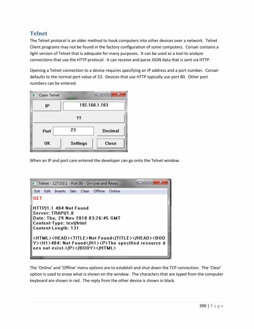
390 | P a g e
Telnet The Telnet protocol is an older method to hook computers into other devices over a network. Telnet
Client programs may not be found in the factory configuration of some computers. Corsair contains a
light version of Telnet that is adequate for many purposes. It can be used as a tool to analyze
connections that use the HTTP protocol. It can receive and parse JSON data that is sent via HTTP.
Opening a Telnet connection to a device requires specifying an IP address and a port number. Corsair
defaults to the normal port value of 23. Devices that use HTTP typically use port 80. Other port
numbers can be entered.
When an IP and port care entered the developer can go onto the Telnet window.
The ‘Online’ and ‘Offline’ menu options are to establish and shut down the TCP connection. The ‘Clear’
option is used to erase what is shown on the window. The characters that are typed from the computer
keyboard are shown in red. The reply from the other device is shown in black.

391 | P a g e
It is possible to type in complete HTTP requests using this system but it is not easy as everything has to
be entered perfectly or the request fails. One answer to this problem is the use of Telnet ‘Inserts’. An
insert is a series of characters that the developer enters into one of the 5 possible Inserts. Each insert
can have a name. The ‘Edit’’Inserts’ menu option shows the names of the 5 inserts.
The button on the left permits editing of the insert.
The name and description of the insert are entered here. The edit button permits entry of multiple lines
of text in the insert. After an insert has been entered the developer can go back to the telnet window
and pick the desired insert from the ‘Inserts’’Trigger #’ menu options. Corsair will send the text of the
insert just as if it has been typed in from the keyboard.
Inserts can be used to send complete HTTP requests but the developer must have a very complete
understanding of the protocol and any encodings that are needed. It is much easier to use one of the 5
available ‘Sets’. They are shown with the ‘Edit’’Sets’ menu option.

392 | P a g e
The button on the left permits editing of the set.
Sets are specially designed for the HTTP protocol. Several windows specify standard and nonstandard
options for the set’s HTTP request.
The ‘View’ button lets the developer preview what the set will send.
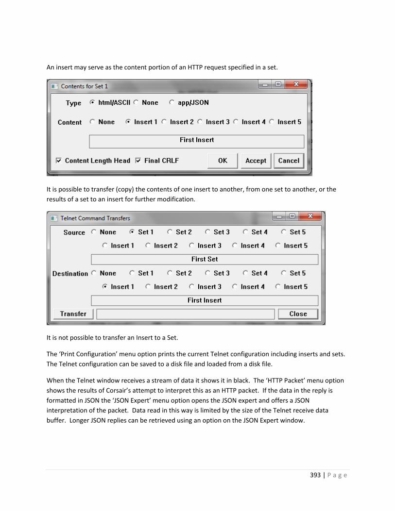
393 | P a g e
An insert may serve as the content portion of an HTTP request specified in a set.
It is possible to transfer (copy) the contents of one insert to another, from one set to another, or the
results of a set to an insert for further modification.
It is not possible to transfer an Insert to a Set.
The ‘Print Configuration’ menu option prints the current Telnet configuration including inserts and sets.
The Telnet configuration can be saved to a disk file and loaded from a disk file.
When the Telnet window receives a stream of data it shows it in black. The ‘HTTP Packet’ menu option
shows the results of Corsair’s attempt to interpret this as an HTTP packet. If the data in the reply is
formatted in JSON the ‘JSON Expert’ menu option opens the JSON expert and offers a JSON
interpretation of the packet. Data read in this way is limited by the size of the Telnet receive data
buffer. Longer JSON replies can be retrieved using an option on the JSON Expert window.
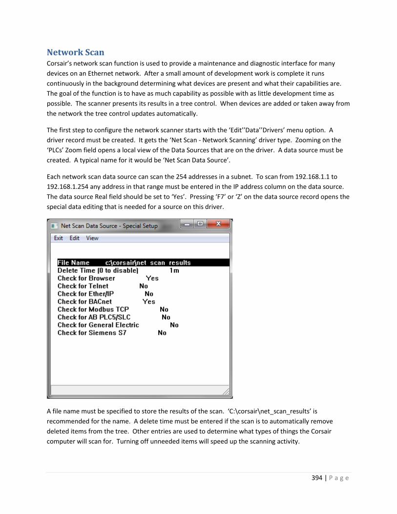
394 | P a g e
Network Scan Corsair’s network scan function is used to provide a maintenance and diagnostic interface for many
devices on an Ethernet network. After a small amount of development work is complete it runs
continuously in the background determining what devices are present and what their capabilities are.
The goal of the function is to have as much capability as possible with as little development time as
possible. The scanner presents its results in a tree control. When devices are added or taken away from
the network the tree control updates automatically.
The first step to configure the network scanner starts with the ‘Edit’’Data’’Drivers’ menu option. A
driver record must be created. It gets the ‘Net Scan - Network Scanning’ driver type. Zooming on the
‘PLCs’ Zoom field opens a local view of the Data Sources that are on the driver. A data source must be
created. A typical name for it would be ‘Net Scan Data Source’.
Each network scan data source can scan the 254 addresses in a subnet. To scan from 192.168.1.1 to
192.168.1.254 any address in that range must be entered in the IP address column on the data source.
The data source Real field should be set to ‘Yes’. Pressing ‘F7’ or ‘Z’ on the data source record opens the
special data editing that is needed for a source on this driver.
A file name must be specified to store the results of the scan. ‘C:\corsair\net_scan_results’ is
recommended for the name. A delete time must be entered if the scan is to automatically remove
deleted items from the tree. Other entries are used to determine what types of things the Corsair
computer will scan for. Turning off unneeded items will speed up the scanning activity.

395 | P a g e
The delete time is used for Corsair’s ‘three strikes’ method. When a device is sensed on the network
Corsair marks that it has a good status and remembers the time. Each time that it can’t read the device
for more than the delete time it counts a strike. The next count after the third strike means the device
will be deleted from the list.
Assume that the delete time is set for 10 minutes. A device is sensed on July 3 at 5 PM. The computer is
shut down and not turned back on until August 4. If it sees the device at that time Corsair remembers
the good status. If it does not see the device at that time Corsair marks it with one strike and
remembers the time. The timing for the second strike begins when the first strike happened, not when
the last good communication occurred. Strike timing is not extremely precise as the scanner has many
things to do. A missing device is guaranteed to not be deleted in less time than 4 times the entered
delete time.
The network scan’s tree control is normally accessed as a register monitor on the data source.
Various monitor and control options appear as the ‘Open’ button on the bottom of the screen. Checking
the ’View’’History’ menu option changes the view to display the scanning status of the item including
the three-strike system.
The ‘Create’ menu section is used to create Corsair tags from network scan results. Administrator
Development must be turned on. The program will not create a tag where one already exists.

396 | P a g e
The ‘All’ create option creates as many tags as Corsair can from the entire network scan tree data. The
‘Selected’ option only does a tag for the tree item that is currently selected. The ‘Selected Family’
option creates for the item that is currently selected and for all the items that are under it.
BACnet Explorer The BACnet Explorer subprogram is accessed through the TCP Expert function. It is used to discover,
monitor, and control devices on a BACnet IP building automation network. Corsair talks BACnet IP
through an Ethernet port. This frequently goes to another device that translates to a serial
communication standard like BACnet MS/TP.
The network scan shows BACnet devices and their properties. It shows objects under the device. It
shows properties under each object. If the ‘Open’ button shows when a tree item is selected the button
is used to open a window to control or monitor that item.
The Door Pseudo-Code Printout This printout produces PLC pseudo-code that helps in the writing of PLC programs for corrections
applications.
PLC Register Monitoring The general PLC Register Monitoring window allows entry of a PLC register address. The Corsair
program then displays the data at that address or a set of consecutive addresses. Several formats are
available for the display. This window also allows for register data entry. Some communications drivers
have specialized versions of the register monitoring window that are specific to that driver.
Data Exports Corsair offers several types of data exports that produce CSV files for use with other software. This
includes a file of labels for door status bits that may be imported into PLC programming software.
Maintenance Windows When an operator is viewing an interface screen he can place the cursor next to a graphic placement. If
he presses the ‘M’ ‘Maintenance’ key Corsair will show a development maintenance window associated
with the placement if one is available.

397 | P a g e
This window shows the data source that the tag is under, it’s address, and other information. The
current value is shown at the bottom. Other types of database records have different maintenance
windows.
The Tag Data Monitoring Window The data monitoring window shows the current values of tag data including all elements of the array
and the addresses of each element.
The Door Data Monitoring Window Corrections versions of the Corsair program offer a special window for monitoring the 16 data bits of a
door.
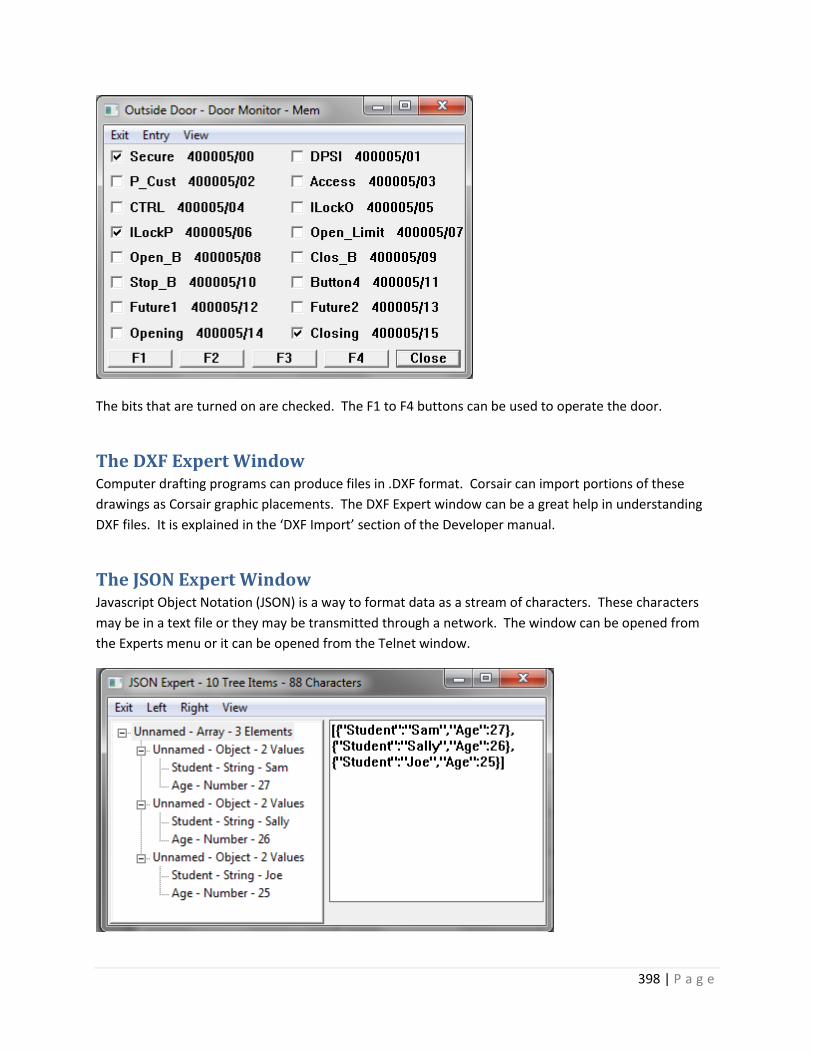
398 | P a g e
The bits that are turned on are checked. The F1 to F4 buttons can be used to operate the door.
The DXF Expert Window Computer drafting programs can produce files in .DXF format. Corsair can import portions of these
drawings as Corsair graphic placements. The DXF Expert window can be a great help in understanding
DXF files. It is explained in the ‘DXF Import’ section of the Developer manual.
The JSON Expert Window Javascript Object Notation (JSON) is a way to format data as a stream of characters. These characters
may be in a text file or they may be transmitted through a network. The window can be opened from
the Experts menu or it can be opened from the Telnet window.

399 | P a g e
The window has a tree control on the left side and a text entry window on the right. JSON data can be
entered or pasted into the right side entry. The ‘Left’’Generate’ menu option converts this to Corsair’s
JSON tree data format and shows it on the left side tree control. (Future) The ‘Right’’Generate’ menu
option translates the tree data into JSON text on the right. Both sides have Clear and Print menu
options.
There are menu options to save the JSON tree data into a file and to load it back again. Some Corsair
drivers depend on properly formatted JSON tree data files. These files can only be produced from the
Corsair JSON expert.
Sometimes a large amount of JSON data may need to be read into the expert. This may be more that
what can be handled directly from the Telnet window. If the JSON expert is accessed from the Telnet
window the ‘Get Data’ menu options can fetch the data directly into the JSON tree. This procedure
bypasses the text entry window on the right side.
Sometimes it is desired to ‘prune’ branches from the JSON tree before saving the tree file. Pruning can
speed up tree data searches and simplify monitoring of tree data. This is done with the specialized
‘Delete’ functions.
Suppose there is an array of objects. Each object contains information about an individual.
[ { “Name”:”Sam”, “Age”:27, “Married”:true,”City”:”Cleveland”},
{ “Name”:”Pete”, “Age”:32, “Married”:false,”City”:”Miami”},
{ “Name”:”Mary”, “Age”:64, “Married”:true,”City”:”Cleveland”},
{ “Name”:”Sue”, “Age”:27, “Married”:true,”City”:”St. Louis”}]
The developer selects an item on the tree and presses the Delete key. This opens up a window that give
him options for his delete.

400 | P a g e
Suppose that the City record for Mary is selected. It has a value of ‘Cleveland’. If One Item is selected
the City value is deleted from her record. The rest of the Mary object stays there and the City
information for the others is untouched.
Deleting Similar objects in all Array Elements means that Corsair will delete the City value in every
record that is in the array.
Deleting All Array Elements with matching Items means that Corsair will delete all records where the
City value is set to ‘Cleveland’. Deleting All Elements with Items that do not match means Corsair will
delete all records where the City value is not equal to ‘Cleveland’.
Protocol Data Corsair’s Help/Program Information menu option opens a window showing buttons to show and print
information about the Corsair program. The ‘Protocol Data’ button is used to open a window with
information about communications protocols that are used by Corsair.
Each of these buttons opens a row and column or a tree display of information about the protocol. They
can be used by the developer to learn about the protocol and to determine what Corsair knows about it.
The Services Expert Windows services are programs that the operating system starts up and operates in the background
without visible windows. The operating system has a database listing programs that are configured to
run as services. The Corsair Services Expert is a window that can be used to list the records in the
services database. To use it the program must be run by a Windows administrator and the developer
must be a Corsair administrator.

401 | P a g e
The tree control on the left side of the expert window shows the programs that are installed as services
with their ‘display’ names. The first item on the right side is the ‘service’ name. The Status item shows
if the service is stopped, running, or in some other state. The Start Type item shows if the service will
start automatically when the computer boots or if it must be started by an operator. The final item
shows where the program file is located and any parameters that are passed to it when it starts.
Any version of the Windows Corsair program has the Services Expert window. If the program has the
‘Diagnostic’ build and license options the Expert can be used to control services. It can change the
startup type of a service and start and stop it. It can create and delete entries from the services
database. This is an extremely powerful feature that must be used very carefully. Accidental deletion of
a critical service could make a computer unusable.
The Expert can be used to create entries in the services database list. One possibility for this is to run
the Corsair program as a service. The ‘Create’ menu option opens a way to do this.

402 | P a g e
The window opens with suggested values to install Corsair as a service. The ‘Binary Path’ entry is an
absolute path specification to the Corsair executable file. One parameter that must be passed to the
program is the word ‘service’ to configure how it is supposed to run. Another parameter is the path to
the computer configuration file that the service is to use. Typically, this file tells Corsair to enable Web
host operation.
Some difficulties may arise when the Corsair service and a copy of Corsair running in a window are
running at the same time using the same computer properties file. Both cannot host web on the same
port at the same time. The best procedure it to use the window version to make a .cfg file for the
service to use. That file needs to be renamed to a different name than the default ‘corsair.cfg’. That
name should then be used in the parameter specification when the service is installed.
CorsairHMI Corrections

403 | P a g e
Introduction
The CorsairHMI program comes with a license file that determines what features of the program are
available to an end user. Corrections features are things that are used in computer systems for jails and
prisons. This manual is used to describe those features. Some of them are available in any version of
the Corsair program. Some are available only if the customer has purchased a Corrections version
license.
Scramble Code Entry CorsairHMI includes a special feature for entreating operator logon PIN numbers in corrections systems.
It is a numeric entry keypad that appears on a touchscreen. The positions of the numbers on the keypad
are different every time it appears. They can be made to change each time a digit is entered. This is
helpful in direct supervision situations where inmates may see the touchscreen. They cannot learn the
operator code by memorizing the positions of the touches. The developer must carefully select size,
color, and font options for the code entry window to make it impossible for the inmates to read. The
selections should be checked after the installation is complete. The code numbers should be changed
periodically.
Hook Codes During interface operation the operator may ‘hook’ to different placements on the screen by touching
the surface of a touch monitor or by clicking the mouse. Many types of placements can be hooked
without being operated. When they are hooked the status window displays data pertaining to the
placement.
Corrections applications frequently require that the PLC has some knowledge of what placement the
operator is hooked to. An example is when door control, closed circuit TV, and intercom are all
integrated. When the operator touches the placement corresponding to a cell door the video switcher
should show him a view of the door and the intercom should be ready to talk to the speaker inside that
cell. This is accomplished through the use of one or more hook code values that can be associated with
each screen placement.
The computer database has a record for each interface computer mode that is running the application.
It provides fields that may be used to link each computer up to four hook code devices. These devices
are used to specify what PLC data addresses receive the hook code values when the operator hooks a
placement.

404 | P a g e
For example, an integer device tagged ‘Camera #’ could be placed on a PLC. Another named ‘Intercom
Station’ could be placed on the same or a different PLC. The first hook code device for a computer would
then be set to ‘Camera #’ and the second to ‘Intercom Station.’ Camera numbers for a video switcher
could range from 1 to 16. Intercom station numbers could be 3-digit values from 100 to 999. As each
hookable placement is put on the screen it would have a camera number entered into the first hook
code value and an intercom station number entered into the second hook code value. The PLC would
then control the video switcher and the intercom so that they would track with the actions of the
operator.
The PLC-based hook code approach to integration tends to work more efficiently than direct computer
control of video and intercom when there are multiple computer interface nodes. Typically, each
interface computer uses different addresses for its hook code devices. They may be created as separate
tags. A common alternative is to utilize computer indexing on the hook code devices. This permits using
the same device tag for hook codes on all computers in the database as long as each computer has a
unique addressing index.
The computer writes the hook value(s) into the appropriate devices one time when the placement is
hooked and the hook code values are non-zero. It writes zeros one time when the placement is
unhooked. Changing directly from one placement to another that has non-zero hook codes will cause
the new values to be written without a zero value between them.
Video Switching
A Corsair operator in a corrections facility typically has a computer monitor that displays CorsairHMI
screens. He may have one or more separate monitors that show him closed-circuit TV (CCTV) images
from within the building. Some systems may display as many as 16 images on sections of a single
monitor. These images are ‘static’ because the same camera is displayed at the same place all the time.
Some systems may have only a single CCTV ‘event’ monitor. An event monitor changes which camera it
is displaying based upon an event. The event may be the operator touching an icon on the Corsair
touchscreen or someone pushing an intercom call button. Many systems have a combination of static
and event-driven CCTV images.
CCTV systems are of two types. One type is based upon conventional video signals that travel through a
shielded coaxial cable. The other type uses ‘IP’ cameras that feed into an Ethernet network.
Vicon Corsair contains a driver to switch cameras on monitors using a Vicon video switcher.

405 | P a g e
Intercom
The Telecor T3 Intercom Driver
Initial Development Initial Testing – the T3 Register Monitor
Required Documents
There are two documents besides this one that the Telecor application developer needs. The other two are printed from the Corsair program. They are the About Driver printout for the T3 driver and the Corsair Telecor T3 protocol document. The About the Driver Printout
The driver About printout can be printed without printing all the other drivers. Go through Edit/Data/Drivers and arrow to the driver that is used to talk to the T3. Press F6 to go to driver single-record editing. The About button is used to make the printout. It lists all the possible addresses that can be used for tags with this driver. A data source must be created on the driver. Pressing F6 while on the data source record leads to single-record editing of the source. The ‘reserved addresses’ button is used to create the tags. Some tags will be created with an array size of 1. These tags will usually be left at that size. Other tags that are initially created with a size of 10 will need to have their size adjusted manually by the developer. For best performance these tags should not be sized much larger than what is required. The end of the About printout shows the value enumerations that are used for the ‘Station LED State’, ‘Station Page State’, and ‘Network LED State’ tags.
Corsair Telecor T3 Protocol Printout
The second document that the developer should print is the Telecor T3 Protocol section of the Corsair Application Manual. This section details the messages that the Corsair program expects from the T3 and the commands that it will send to the T3. The person that does the T3 programming will need to study this so that he can determine what he needs to do. The manual section is printed through File/Print/Application Manual. Click on ‘Print’ to select a printer. Click on ‘Print Nothing’ to shut off all manual sections. Go to the ‘Reference’ tab. Check ‘Telecor T3 Protocol’ and click on ‘OK’.

406 | P a g e
The ‘T3 Default Messages’ are messages sent from the T3 to the Corsair computer. They correspond to the default messages that are suggested by Telecor. ‘Default Commands’ work in the opposite direction. They go from the Corsair computer to the T3. Special Messages and Commands will have to be configured as a part of the T3 programming work.
Station State
The driver supports three tag addresses that are integer values corresponding to the status of intercom stations. They are ‘Station LED State’, ‘Station Page State’, and ‘Network LED State’. Each of these tags should be sized to accommodate the number of indexes that are needed on the system. The ‘Station LED State’ tag contains integer values ranging from 0 through 6 to indicate what the station is doing. The About Driver printout for the Telecor T3 driver gives the definitions for each of these states. The state value can be used to modify what the operator sees on the screen for each intercom station. The developer may choose to place an ellipse to simulate an LED. The state value can be used as an index into a color set for the ellipse so that the LED changes color. A more common application would be to use an icon set. The state value would be used to determine what icon the operator sees. When the operator does paging the Telecor T3 does not send messages to the Corsair computer to show it what stations are involved. This would require too many messages for the serial port. The developer may want to show on the computer screen which stations are being paged. This is the function of the ‘Station Page State’ tag address. Normally the value of the page state is identical to the value of the LED state. When the station is being paged the page state value changes to a 7. This enables a separate color or icon in the set to show paging status. If a system does not utilize paging either the ‘Station LED State’ or ‘Station Page State’ tags can be used. Performance would be improved by using ‘Station LED State’ and deleting ‘Station Page State’. If it is desired to indicate paging the ‘Station Page State’ tag is the correct choice. For this tag to work properly entries must be made in the ‘Page Zones’ and ‘Page Stations’ auxiliary databases. The section on Paging Indication that is later in this document shows how that is to be done. Network LED State
Multiple T3 intercoms cam be linked together on a Telecor network where each T3 communicates to a separate Corsair computer over a serial port. Assume that the building A T3 has intercom stations 101 to 160 on it. The building B T3 has intercom stations 201 to 260 on it. It is possible for the Building B T3 to talk to station 122 in Building A using the Telecor network. When this happens the ‘Station LED State’ and ‘Station Page State’ tags in the Building A Corsair computer will not show the operator tat someone else is talking to the station. This becomes possible with the ‘Network LED State’ tag. The first step for this to work is that the T3 programmer must enable the option that sends all messages from all the T3s to every computer. The Corsair developer must then enter a separate data source into his application database for each T3 that is on the network. Contact your Corsair dealer for more information as to how to do this. The second document that the developer should print is the Telecor T3 Protocol section of the Corsair Application Manual. This section details the messages that the Corsair

407 | P a g e
program expects from the T3 and the commands that it will send to the T3. The person that does the T3 programming will need to study this so that he can determine what he needs to do. The manual section is printed through File/Print/Application Manual. Click on ‘Print’ to select a printer. Click on ‘Print Nothing’ to shut off all manual sections. Go to the ‘Reference’ tab. Check ‘Telecor T3 Protocol’ and click on ‘OK’.
Dial Number Indexing
Each intercom station on the T3 system has a dial number. 41903 would be a possible number. There are several Tag data addresses on the Corsair driver that are arrays. Each element of these arrays corresponds to a station dial number. The ‘Station LED State’ tag is an example of one of these arrays. Corsair defaults to the simplest situation where array element indexes correspond directly to intercom dial numbers. Dial number 41903 corresponds to index 41903 of the array. This system is easy to develop because the tags for the icon for that station would use array index 41903. The problem with simple dial number indexing is that the tags have to be sized for the highest dial number that is on the system. If dial number 41903 is present the tags must have a size of at least 41904 to allow for indexes 0 through 41903. This is true even if there are actually only 200 intercom stations on the system. The Corsair program performs lots of processing on T3 tag data to calculate paging, call group, and Network LED status. With large tag array sizes this processing can become very slow and system performance will be unacceptable. The answer to this problem is to use the Stations auxiliary database. The Stations database is used to map Station dial numbers to Tag array indexes. Now our example tags can be sized at 200 instead of 41904. Dial number 41903 can be linked in the database to tag index 1. Tags on the icon for that station would now use an index value of 1 rather than 41903. Synchronization
It is possible with systems where intercoms communicate with computers for the two processors to lose data synchronization. If this occurs the computer may not show a call-in that is present or it may show a call-in that is no longer active. Two synchronization techniques can be used with the Corsair T3 driver. The first option for synchronization is for the Corsair computer to send a CLR clear command when it is first started. It then resets all of its data to zero to clear all calls. The T3 does the same thing. The assumption is that the computer and T3 are synchronized at this point and they will stay that way. The only advantage of this option is that it requires minimal programming on the T3. One of the disadvantages is that when a Corsair computer is offline and it restarts all T3 call status information is lost. Another disadvantage is that the system has no way to recover from lost communications characters. The answer to these problems is the GCS Get Console State special command. The Corsair developer can block the sending of the CLR command on startup. He then programs a nonzero synchronization time interval on the data source record. Now the Corsair computer will send a GCS command when it starts and at regular time intervals after that. The T3 is to respond to the GCS with a complete listing of

408 | P a g e
the status of all stations. The T3 programmer must configure the intercom to properly handle the GCS command. Call Groups
Many times it is desirable to show an indication on the Corsair screen if one or more calls have been received from a group of stations. A graphic screen may show an overview of a 5-story building. There may be 5 ‘keys’ (buttons) on the screen to jump to detail views of each of the 5 floors. The developer may want to have each key blink if there is an active call from that floor. He will want to assign 5 non-zero call group indexes. In this case indexes 1 through 5 will correspond to floors 1 through 5. Three tag addresses are used to set up external page paths with the ‘Call Groups’ auxiliary database. The addresses are: Group Index Start Station Index End Station Index Each record of this database assigns a range of station index numbers to a call group. The database may look like this: Group Index Call Group Start Call Group End 1 100 199 2 200 299 3 300 399 4 400 499 5 500 599 1 602 0 5 708 0 Zero is not a valid group index. A start or end value of zero is ignored. In this example a 3## call will indicate on the third floor call group. A 1## call or a call from 602 will show on the first floor call group. A 5## call or a call from 708 will show on the fifth floor call group. The ‘Call Group Active’ tag address is used for the indicators that come on when the groups are active. The indexes of this tag correspond to the databases Group Indexes. Index 3 of this tag should be used to change color or blink the key for the third floor. Index 5 would be the indication for the fifth floor. The ‘Call Group Active’ tag is calculated from the data in the ‘Station Calls’ tag. It will not work correctly if the ‘Station Calls’ tag is not present or is not large enough. Paging Indication
Dial numbers can be configured by the T3 programmer to initiate pages to multiple intercom stations. If
it is desired to have the ‘Station Page State’ tag properly show what stations are being paged the zone
information must be programmed into the Corsair system. This is done with the ‘Page Zones’ and ‘Page
Stations’ auxiliary databases.
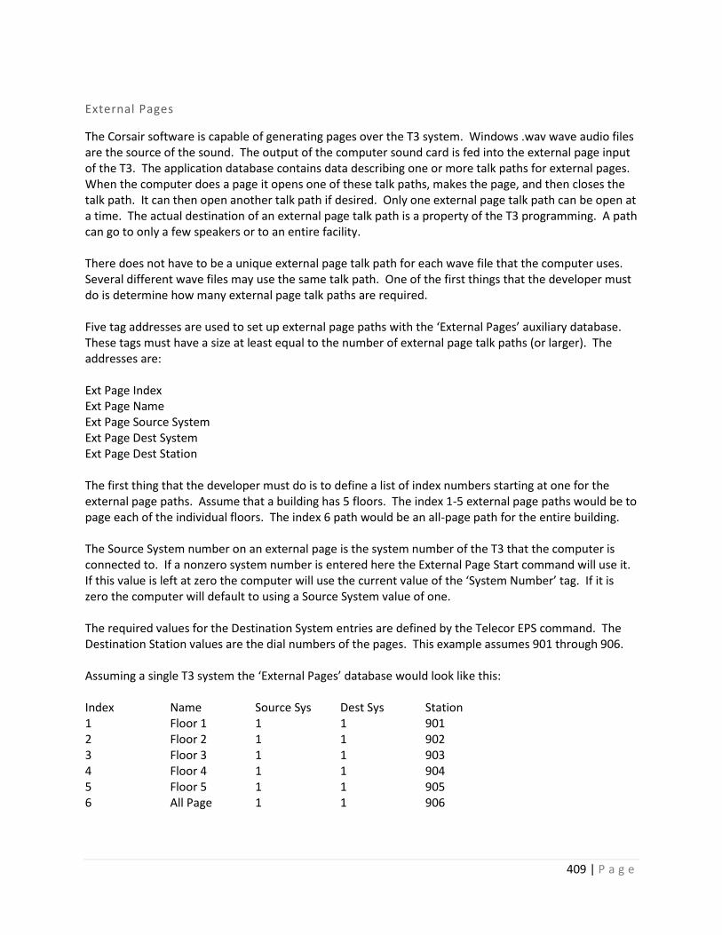
409 | P a g e
External Pages
The Corsair software is capable of generating pages over the T3 system. Windows .wav wave audio files are the source of the sound. The output of the computer sound card is fed into the external page input of the T3. The application database contains data describing one or more talk paths for external pages. When the computer does a page it opens one of these talk paths, makes the page, and then closes the talk path. It can then open another talk path if desired. Only one external page talk path can be open at a time. The actual destination of an external page talk path is a property of the T3 programming. A path can go to only a few speakers or to an entire facility. There does not have to be a unique external page talk path for each wave file that the computer uses. Several different wave files may use the same talk path. One of the first things that the developer must do is determine how many external page talk paths are required. Five tag addresses are used to set up external page paths with the ‘External Pages’ auxiliary database. These tags must have a size at least equal to the number of external page talk paths (or larger). The addresses are: Ext Page Index Ext Page Name Ext Page Source System Ext Page Dest System Ext Page Dest Station The first thing that the developer must do is to define a list of index numbers starting at one for the external page paths. Assume that a building has 5 floors. The index 1-5 external page paths would be to page each of the individual floors. The index 6 path would be an all-page path for the entire building. The Source System number on an external page is the system number of the T3 that the computer is connected to. If a nonzero system number is entered here the External Page Start command will use it. If this value is left at zero the computer will use the current value of the ‘System Number’ tag. If it is zero the computer will default to using a Source System value of one. The required values for the Destination System entries are defined by the Telecor EPS command. The Destination Station values are the dial numbers of the pages. This example assumes 901 through 906. Assuming a single T3 system the ‘External Pages’ database would look like this: Index Name Source Sys Dest Sys Station 1 Floor 1 1 1 901 2 Floor 2 1 1 902 3 Floor 3 1 1 903 4 Floor 4 1 1 904 5 Floor 5 1 1 905 6 All Page 1 1 906

410 | P a g e
The indexes in this database correspond to elements in the ‘Clear Talk Path’, ‘Request Talk Path’, and ‘Talk Path Ready’ tags. The [0] element of each of these tags is not used. The [3] element of each of these tags is used to page the third floor. The [6] element of each of these tags is used to do an All-Page. Three tag addresses are used to coordinate the programs sound logic with the Telecor T3 driver. Each of these tags must have a size at least equal to the number of external page talk paths plus one. They may be sized larger if desired. These addresses are: Clear Talk Path Request Talk Path Talk Path Ready The next development step is to define the desired sounds. The Sounds database is accessed under Edit/Graphics/Sounds. Each sound can consist of one or more wave files with an optional delay before each wave file is played. Zooming on the ‘Files’ zoom field allows listing the wave files. After the wave files are entered, escaping back to the Sounds database. The ‘Play’ field allows the developer to test for the expected sound. The next step is to fill in the rest of the fields on the Sound record. The RTP Tag field is linked to the Telecor drivers ‘Request Talk Path’ tag. The RTP Index field is set between 1 and 6 to indicate the desired talk path – it would be 5 for a fifth floor page. The RTP Value field is always set to ‘1’ for this driver. The TPR Tag field is linked to the Telecor drivers ‘Talk Path Ready’ tag. The TPR Index must be set to the same value as the RTP index. The CTP Tag field is linked to the Telecor driver’s ‘Clear Talk Path’ tag. The CTP Index must be set to the same value as the RTP and TPR indexes. The CTP Value field is always set to ‘1’ for this driver. When the computer wants to use a talk path for an external page it sets a value of 1 into an index on the Request Talk Path tag. The driver looks at what index is nonzero to help it find the correct entry in the External Pages database. It uses this information to form and send an External Page Start command through the serial port to the Telecor T3. When the T3 replies that the command is successful the driver turns on the correct index of the Talk Path Ready tag. The Corsair computer plays the wave file. It then turns on the correct index of the Clear Talk Path tag. The driver sends External Page End to the T3. The sequence works like this: Sound Program Telecor Driver Program Telecor T3 Set RTP tag to 1 Send EPS command Open Page Talk Path Reply to EPS Set TPR tag to 1 Play the sound Set CTP tag to 1 Send EPE command Close Page Talk Path The ‘Timeout’ field specifies how long the Corsair program will wait for the ‘Talk Path Ready’ signal from the Telecor. If it does not get TPR within this amount of time the wave file is played and the sequence

411 | P a g e
continues normally. The timeout should be set to a value longer than the longest possible T3 response time. Note that External Pages should receive a very high priority in the T3 program for this system to work. If the timeout is set to zero or if a TPR tag is not listed the computer will play the wave file immediately without waiting for the T3 to open a path. SQL Event Logging
Call-ins generated from the T3 may be logged into an SQL database using the Corsair event logging system.
Duress Duress and man-down systems are used to alert others when an individual has been attacked or that
some form of emergency help is needed. Corsair can interface to a wide variety of duress equipment.
Guard Tour Guard tour systems are used to verify that corrections officers make proper rounds inspecting parts of a
facility.
Access Control Access control systems are used to permit properly authorized individuals to get into restricted areas of
a facility. Corsair can be used to interface between an access control system and a video management
system. It can switch camera views on a monitor when a card is scanned. Some systems may show a
picture of the individual that the card is issued to. If the person at the door matches the picture the
operator opens the door.
The access control systems drivers in Corsair require both ‘Access Control’ and ‘Corrections’ capabilities.
These may be verified from the main menu by clicking on ‘Help”’About’ and selecting the ‘Build’ option.
This opens the Build Properties window.

412 | P a g e
Both ‘Build’ and ‘License’ must be checked for Access Control and Corrections on this window. If ‘Build’
is not checked the developer must get a different version of the Corsair program. If ‘License’ is not
checked CorsairHMI must be contacted for a different license file.
Doors Corrections institutions usually have electrically operated doors. Any version of the Corsair program can
be used along with a PLC to operate doors. This type of door operation is similar to what could be done
with a general-purpose interface program. Corsair offers more advanced door operations with its
corrections version license option. It should be considered for any facility with more than 10 controlled
doors.
Door Types
The first step for doing the PLC programming of a CorsairHMI door is to determine its type. The type
determines show the F1 through F4 keys are used to control the door. It also determines the
requirements for the secure indication. The secure indication is the signal from the PLC to Corsair that
the door is properly closed.
The ‘Monitored’ type is for a door whose status is shown on the computer but it is not controlled by the
PLC. Mechanically keyed doors are monitored. They have some combination of a door position and a
bolt position switch to wire to a PLC input for the secure indication. The F1-F4 keys are not used for
monitored doors.
The ‘Half-Cycle’ type door is controlled by the PLC. It is a solenoid or a motor lock without mechanical
hold-back of the bolt. It uses the F1 key for an unlock button and the F2 key for a lock button. Usually
F1 energizes the solenoid and F2 de-energizes it. The Half-Cycle name comes from motor locks where

413 | P a g e
F1 makes the motor rotate through half its cycle and F2 finishes the rotation. The locked or unlocked
status of the door must not change when the PLC power is cycled. Half-cycle locks are a frequent choice
for fire egress doors. Sometimes the solenoid is energized to secure the door in these applications.
The ‘Full-Cycle’ type door is controlled by the PLC. They are motor or solenoid locks with mechanical
hold-back. The motor runs a cycle or the solenoid energizes for a period of time. The bolt is pulled in. It
stays retracted until someone pulls the door open and then shuts it. The interface has an F1-Unlock
option. There is no lock option from the computer.
Full cycle locks are used in high traffic applications where the operator unlocks the door. He does not
have to wait for someone to go through it before he tells the door to lock. Full cycle locks are not to be
used in fire egress applications.
The ‘Slider’ type is used for sliding doors and gates. They are powered open or closed and capable of
being stopped in mid-travel. The interface has F1-Open, F2-Close, and F3-Stop options.
PLC logic for a slider must include anti-plugging timers. Plugging a motor means taking it from open to
close or close to open without allowing it to come to a stop. Plugging is damaging to electrical and
mechanical components. When a motor that is opening a door stops in mid-travel the door will tend to
rock open slightly and then rock back in the closed direction. If the anti-plugging timer is properly set
the motor will restart in the close direction at just the right time to make for smooth motion with a
minimal amount of noise and wear on the gear train. To avoid delays the programmer must take care
that the anti-plug timer only is in use when it is needed. If the door is fully closed the timer is not
needed to start open motion.
‘Dual-Cycle’ type doors are doors that can be operated in two different modes – both Full and Half cycle.
The interface has F1-Unlock, F2-Lock, and F4-Hold options. F1 is used for a full-cycle operation where
the door will relock by itself when closed. F4 is used for the half-cycle unlock function where the door
will remain unlocked until F2 is used to lock it.
PLC operated doors are frequently interlocked in corrections applications. If two doors are in an
interlock scheme only one of them can normally be opened at a time. Interlocks may need to be shut
off for special situations like firefighter access.
Door Registers
PLC door data is kept in a 16-bit register. Each of the bits has a different function depending on the type
of the door. Some bits act like Corsair indicators where the PLC turns them on and off and the interface
displays the status. Some bits act like Corsair switches where the computer turns them on and off and
the PLC uses the status. Some bits act like Corsair buttons where the computer turns them on and the
PLC shuts them off. One of the most important considerations with door programming is proper
behavior when the PLC power is cycled. Generally the switch type bits must be retentive. That means
that whatever status they had when the power is shut off is still there when the power is turned back
on. The button type bits must be shut off when the power restarts. Button actions that were

414 | P a g e
performed with the PLC in Halt need to be zeroed out and ignored on the first scan. Some indicators
need to be retentive and some are not.
A programmer using a PLC with Modbus style addresses may place the first door at bit 00001 through
bit 00016. The second door may take bit 00017 through bit 00032. Another possibility is for the first
door to use Holding Register 40001. The bits would be 40001/0 to 40001/15. The second door could go
into Holding Register 40002. Input Registers like 30001 cannot be used for doors since the computer
cannot write data to them. Inputs bits like 10001 cannot be used for the same reason.
The Modbus protocol does not specify the power cycling retention rules for different data types. It is up
to the PLC manufacturer so their documentation must be consulted for retention rules. Frequently the
door status data is held in retentive memory. The programmer defines a single ‘Power-Up’ boolean
variable. It comes up False (0) on the first scan when the PLC starts. 30 seconds later it is set to True (1).
Door operations are not allowed until Power-Up is true. This allows time for remote I/O and peer-to-
peer communications to get started first. This use of the Power-Up signal can help guarantee that the
PLC follows the proper memory retention rules.
Another concern for the PLC programmer is the method that CorsairHMI must use to change the bit
data of the type that he has chosen for the door register. Data in Modbus 0#### coils can be written on
an individual coil basis. Corsair can turn a button on without changing any of the other bits in the
register. 4#### holding registers are a different issue. Some PLC’s support a bitmasked write command
where Corsair sends a pattern of 1s and 0s that the PLC uses to only change the desired bit of the
register. If a PLC does not support this command Corsair must use a Read-Modify-Write (RMW)
operation. It reads the holding register and then writes that value back to the PLC with the desired bit
changes. Problems can occur if the PLC logic changes bits in the short time between when Corsair reads
the value and then writes it back. Any PLC logic, including the samples given here, must be evaluated by
the PLC programmer to see that it will always work correctly with a RMW operation. Bitmasked writes
should be used whenever possible to avoid issues and speed up door operations.
This document refers to the bits of the door status register as bit 0 through bit 15. Bit 0 is the least
significant bit and bit 15 is the most significant. If a door is located at Modbus coil addresses 00017
through 00032 coil 00017 is bit 0 and coil 00032 is bit 15. A door located at Modbus Holding Register
address 40010 has 40010/0 for bit 0 and 40010/15 for bit 15.
Each of the 16 different bits of a door register has a name and function that depends on the door type.
There are some general rules that can be considered before looking at each of the 5 door types. In cases
where a bit is supposed to always be on or off the register bits are not to be trusted as they can be
changed from external data communications. PLC logic should be written to force these bits to always
be the correct value.
Bit 0 is always used as the ‘Secure’ bit. It is an indicator that is turned on and off by the PLC. It should
be on only if all conditions securing the door are true. This bit is what Corsair uses to show the status of
the door on the screen. The programming for the Secure bit varies with the type of the door. It is
usually at the end of the logic. The Monitored door is the only type where the Secure bit is only

415 | P a g e
dependent on the Door Position Switch indication. For all the PLC-controlled door types the door is
secure if the switch is correct and the PLC is not trying to open the door. This will help to prevent false
secure indications when switches are defective.
Bit 1 is always used as the ‘DPSI’ ‘Door Position Switch Indication’ bit. It acts as an indicator. Most door
hardware provides a signal to a PLC input that shows the door is secure. This signal is usually from more
than one switch wired in series. There may be both a door position and a bolt position switch. The DPSI
indicator is controlled from one or more DPS PLC inputs in a series (AND) configuration. This is usually at
the beginning of the logic. The DPSI bit is used as a part of the logic for the status of the Secure bit.
Bit 2 is sometimes used as the ‘P_Cust’ ‘Protective Custody’ bit. It acts like a switch. The computer
turns it on (1) for the door to have protective custody status. The operator will then have to answer a
special prompt to open the door. If the computer turns the bit off (0) the door can be operated
normally. The status of this bit must be retained through a power failure. Some projects may require a
high-security door to always have protective custody. Other doors should never have that status. In
these cases PLC logic should explicitly force the bit on or off.
Bit 3 is sometimes used as the ‘Access’ ‘Inmate Access’ switch. If it is on the inmate can open his cell
door through some means. If it is off the inmate cannot open the door. It must be retentive.
Bit 4 is sometimes used as the ‘CTRL’ ‘Interface Control’ switch. The use of this switch is entirely up to
the PLC programmer. The Corsair program can turn it on and off but it makes no assumptions about
what the switch is used for. Cell lighting is a possibility. It may or may not retain at the discretion of the
PLC programmer.
Bit 5 is sometimes used as the ‘ILockO’ ‘Interlock On/Off’ switch. If the computer turns it on (1) the
door’s interlocks are active and it cannot be opened until other doors are secure. If the computer turns
it off (0) the interlock has been overridden and the door can be opened. It must be retentive. Some
high-security applications may require this bit to be forced on in PLC logic so the interlock cannot be
shut off. Firefighter access must be considered in making this decision.
Bit 6 is sometimes used as the ‘ILockP’ ‘Interlock Permissive’ indication. The PLC turns this bit on if all
other doors in the interlock scheme are secure so the door may be opened. If the ILockO bit is off the
ILockP bit is turned on. If a door is not interlocked ILockP should be turned on all the time.
Assume that doors A, B, C, and D are all interlocked so only one can be opened at a time. Ladder logic
for the ILockP on door A would look as follows:
Secure_B Secure_C Secure_D ILockP_A
---| |---------------| |-----------| |-------+---------( )-----
ILockO_A |
---|/|------------------------------------------+

416 | P a g e
If door E is not interlocked the ILockP bit should be forced on.
ILockP_E
----------------------------------------------------------( )-----
Bits 8, 9, 10, and 11 are used for the F1, F2, F3, and F4 keys. The purpose varies with door type but in
each case they act like button tags. Corsair turns the bit on when the operator hits the key and the PLC
turns it off after performing the desired action.
Any of the 4 button bits that are used for a lock need to perform their action if and only if the Power_Up
signal is true. After examining the bits the PLC should always shut them off.
Button
----------------------------------------------------------( U )-----
Keys hit before Power_Up will be ignored. This effectively makes the buttons nonretentive.
Bits 12 is unused and can be used for any purpose. Bit 13 is reserviced for future versions of the Corsair
program.
There is a Door data maintenance popup available from an operator screen. Hook the cursor to a door
placement and press the ‘M’ maintenance key.

417 | P a g e
The maintenance window shows the name of the door, what PLC it is on, its type, the address of each
door register bit and its current on-off status.
The following sections give specific information as to the bit assignments for each of the door types.
Some suggestions for PLC logic are included. In every case the PLC programmer must assume final
responsibility for what the PLC does. Lockdown and Fire Egress must be taken into account.
Monitored Doors
Bit 0 – Secure – Indicator
Bit 1 – DPSI – Door Position Switch Indication - Indicator
Bit 2 – P_Cust – Protective Custody – Switch Do not use on a monitored door.
Bit 3 – Access – Switch
Bit 4 – CTRL – Interface Control – Switch
Bit 5 – Unused1 – Switch Use for any purpose
Bit 6 – Unused2 – Available for any use

418 | P a g e
Bit 7 – Unused3 – Available for any use
Bit 8 – Button1 – F1 Key – Button Do not use
Bit 9 – Button2 – F2 Key – Button Do not use
Bit 10 – Button3 – F3 Key – Button Do not use
Bit 11– Button4 – F4 Key – Button Do not use
Bit 12 - Future1 - Do not use Reserve for future versions of Corsair
Bit 13 - Future2 - Do not use Reserve for future versions of Corsair
Bit 14 – Unused4 – Available for any use
Bit 15 – Unused5 – Available for any use
Pseudo Code:
DPSI = DPS; (* Copy DPS input into the DPSI Indicator *)
SECURE = DPSI; (* Copy the DPSI Indicator into the Secure bit *)
Ladder:
DPS % I DPSI
-----| |---------------------------------( )---
DPSI Secure
-----| |---------------------------------( )---
The door is secure when the switch is on.
Half-Cycle Doors
Bit 0 – Secure – Indicator
Bit 1 – DPSI – Door Position Switch Indication - Indicator
Bit 2 – P_Cust – Protective Custody – Switch
Bit 3 – Access – Switch
Bit 4 – CTRL – Interface Control – Switch

419 | P a g e
Bit 5 – ILockO –Interlock On/Off - Switch
Bit 6 – ILockP –Interlock Permissive – Indicator
Bit 7 – Unused1 – Available for any use
Bit 8 – Unlk_B – Unlock F1 Key – Button
Bit 9 – Lock_B - Lock F2 Key – Button
Bit 10 – Button3 – F3 Key – Button Do not use
Bit 11– Button4 – F4 Key – Button Do not use
Bit 12 - Future1 - Do not use Reserve for future versions of Corsair
Bit 13 - Future2 - Do not use Reserve for future versions of Corsair
Bit 14 – Hold_Open – Indication
Bit 15 – Unused2 – Available for any use
The Hold-Open bit should be retentive, especially for a fire egress door.
Pseudo Code:
DPSI = DPS; (* Copy DPS input into the DPSI Indicator *)
Calculate ILockP
If Unlk_B AND ILockP and Power_Up – Turn on Hold_Open
IF Lock_B AND Power_Up – Turn off Hold_Open
Reset Unlk_B to 0
Reset Lock_B to 0
Copy Hold_Open to External Output %Q
SECURE = DPSI AND (NOT Hold_Open;
Ladder

420 | P a g e
Full-Cycle Doors
Bit 0 – Secure – Indicator

421 | P a g e
Bit 1 – DPSI – Door Position Switch Indication - Indicator
Bit 2 – P_Cust – Protective Custody – Switch
Bit 3 – Access – Switch
Bit 4 – CTRL – Interface Control – Switch
Bit 5 – ILockO –Interlock On/Off - Switch
Bit 6 – ILockP –Interlock Permissive – Indicator
Bit 7 – Unused1 – Available for any use
Bit 8 – Unlk_B – Unlock F1 Key – Button
Bit 9 – Button2 - F2 Key – Button Do not use
Bit 10 – Button3 – F3 Key – Button Do not use
Bit 11– Button4 – F4 Key – Button Do not use
Bit 12 - Future1 - Do not use Reserve for future versions of Corsair
Bit 13 - Future2 - Do not use Reserve for future versions of Corsair
Bit 14 - Cycle – Indicator
Bit 15 – Unused2 – Available for any use
With a full-cycle lock the output is held on for a fixed period of time. Full cycles may be solenoids or
motors. If it is a solenoid the timing must be long enough to make sure the bolt is pulled solidly into the
mechanical holdback. Motor Full Cycles sometimes use a microswitch on a cam to keep the motor
running through a complete cycle. The minimum and maximum times for the output need to be
determined. To get the minimum time reduce the timing until the lock occasionally does not do a
complete cycle since the motor doesn’t have enough movement to get to the latching microswitch. To
get the maximum time increase the timing until the motor occasionally does two complete cycles
instead of one. The correct time to use for the setpoint is halfway between this minimum and
maximum.
Pseudo Code:
DPSI = DPS; (* Copy DPS input into the DPSI Indicator *)
Calculate ILockP
If Unlk_B AND ILockP AND Power_Up – Turn on Cycle
If Time - Turn off Cycle

422 | P a g e
On-Delay Timer – Input is Cycle, Output is Time
Reset Unlk_B to 0
Copy Cycle to External Output %Q
SECURE = DPSI AND (NOT Cycle);
Ladder: (Not Complete)
Sliders
Bit 0 – Secure – Indicator
Bit 1 – DPSI – Door Position Switch Indication - Indicator

423 | P a g e
Bit 2 – P_Cust – Protective Custody – Switch
Bit 3 – Access – Switch
Bit 4 – CTRL – Interface Control – Switch
Bit 5 – ILockO –Interlock On/Off - Switch
Bit 6 – ILockP –Interlock Permissive – Indicator
Bit 7 – Open_Limit – Optional Door Fully Open Indication
Bit 8 – Open_B – Open F1 Key – Button
Bit 9 – Close_B - Close F2 Key – Button
Bit 10 – Stop_B – Stop F3 Key – Button
Bit 11– Button4 – F4 Key – Button Do not use
Bit 12 - Future1 - Do not use Reserve for future versions of Corsair
Bit 13 - Future2 - Do not use Reserve for future versions of Corsair
Bit 14 – Opening – Indication
Bit 15 – Closing – Indication
Both the Opening and Closing indications need to go to zero when Power_Up is not on.
Many times sliders and gates do not have full-open switches wired to the PLC. The Open output is
energized for a fixed time period in these cases. The Close output is shut off when the closed limit
switch is reached. It needs to also be timed off in case the limit switch is defective. Outputs without
timeouts may be dangerous for maintenance people working on the door as they could cause
unexpected door operation. Timeouts should be set for the normal full travel time plus a few seconds.
Pneumatic doors may have more variations in travel times than motorized doors so they should get
longer timeouts.
Pseudo Code:
DPSI = DPS; (* Copy DPS input into the DPSI Indicator *)
SECURE = DPSI; (* Copy the DPSI Indicator into the Secure bit *)
Ladder: (Not complete)

424 | P a g e

425 | P a g e
DPS % I
Dual-Cycle Doors
Bit 0 – Secure – Indicator

426 | P a g e
Bit 1 – DPSI – Door Position Switch Indication - Indicator
Bit 2 – P_Cust – Protective Custody – Switch
Bit 3 – Access – Switch
Bit 4 – CTRL – Interface Control – Switch
Bit 5 – ILockO –Interlock On/Off - Switch
Bit 6 – ILockP –Interlock Permissive – Indicator
Bit 7 – Cycle – Full Cycle Indication
Bit 8 – Unlk_B – Unlock F1 Key – Button
Bit 9 – Lock_B - Lock F2 Key – Button
Bit 10 – Button3 – F3 Key – Button Do not use
Bit 11– Hold_B – Hold F4 Key – Button
Bit 12 - Future1 - Do not use Reserve for future versions of Corsair
Bit 13 - Future2 - Do not use Reserve for future versions of Corsair
Bit 14 – Hold_Open – Indication
Bit 15 – Unused1 – Available for any use
The timing guidelines for a dual-cycle door are the same as for a full-cycle.
Pseudo Code:
DPSI = DPS; (* Copy DPS input into the DPSI Indicator *)
Calculate ILockP
If Unlk_B AND ILockP AND Power_Up – Turn on Cycle
If Time – Turn off Cycle
On-Delay Timer – Input is Cycle, Output is Time
If Hold_B AND ILockP AND Power_Up – Turn on Hold_Open
If Lock_B – Turn off Hold_Open
Reset Unlk_B to 0

427 | P a g e
Reset Lock_B to 0
Reset Hold_B to 0
External Output %Q = Cycle OR Hold_Open
SECURE = DPSI AND (NOT Cycle) AND (NOT Hold_Open);
Ladder: (Not complete)
Corsair BACnet Access Control Shims The CorsairHMI program has build and licensing options for use with Access Control systems.
Manufacturers of these systems do not seem to have standardized protocols to communicate with their
servers. They typically have some sort of graphic ‘map’ software that talks very well to their system but
not well to other equipment. If an integrator wants to interface to an access control system he must use

428 | P a g e
their ‘SDK’ or ‘API.’ This involves programming for tasks that should be doable at a technician level. It
may involve writing project-specific .NET compatible code. This is clearly not acceptable.
The CorsairHMI program uses ‘shim’ or ‘middleware’ software between each manufacturers API and
Corsair. Each shim translates from the API to a standardized form that Corsair can use. The Corsair
developer can use the same procedures for different brands of Access Control equipment as the data
from each is ‘normalized’ to the same standard.
The shims do not need to utilize the full capabilities of each manufacturer’s API. Typically they need to
view door status, open doors, monitor inputs, and control outputs. The shims should not perform any of
the ‘IT’ functions like adding or deleting credentials. Access control software should be administered by
access control software, not by operator interface software.
The shim should require very little configuration. Typically a username, password, and maybe a server
address is adequate. The Corsair developer should not have to put a list of doors into the shim. It should
automatically discover that list. The next requirement for an ideal shim is that Corsair can automatically
discover that list.
Facilities with multiple interface computers should have the option of only requiring one instance of the
shim. This is to minimize communications transfers to the access control server. The shim must be
network accessible from several computers. This should be using an open vendor-independent protocol.
CorsairHMI has chosen BACnet/IP for this purpose. BACnet has software ‘objects’ that are specifically
designed for Access Control. It has a well-defined discovery mechanism with free BACnet explorers. The
shim could be used by itself without Corsair to tic the access control system to a building automation
controller.
Each door on the access control system should show on the BACnet side as ‘Access Door’ object type.
Card readers show as an ‘Access Point’ object type. Output points that are not used for doors should
show as a ‘Binary Output’ object type. Discrete inputs should show as a ‘Binary Input’ type. BACnet
instance numbers for these objects are determined by the requirements of the shim.
Corsair Access Control Description Architecture
Corsair shims can permit discovery of the access control system using a standard BACnet explorer.
Corsair includes a minimal explorer that can be used to generate door and tag records based upon data
it receives from the shim.
BACnet includes a ‘structured view’ object type that can be used to organize data in a tree-style manner.
Corsair can generate access control system architecture documents if the shim generates structured
view objects in a specified pattern.

429 | P a g e
SV-Server
SV-Site 1
SV-Site 1 Panel List
SV-Site Panel 1
SV-Door List
ACD-Door
ACD-Door
SV-Reader List
AP-Reader
AP-Reader
SV-Input List
BI-Input
BI-Input
SV-Output List
BV-Output
BV-Output
SV-Site 1 Panel 2
SV-Site 1 Room List
AZ-Access Zone
AZ-Access Zone
SV-Site 2
Many access control systems may not be able to generate all the features of this pattern.
Each Structured View BACnet object has a Node_Type property. Suggested values of these properties
are:

430 | P a g e
SV-Server SYSTEM
SV-Site AREA
SV-Panel List COLLECTION
SV-Room List COLLECTION
SV-Door List SECTION
SV-Reader List SECTION
SV-Input List SECTION
SV-Output List SECTION
Each Access Point object that represents a reader should support the following properties:
Property – Access Doors
Property – Zone To
Property – Zone From
Each Access Zone that represents a room :
Property_Entry Point
Et Point
The Corsair CorKey Shim CorsairHMI can be used to Monitor and control doors that are on a Keyscan access control system. The
Keyscan system uses an SDK (Software Development Kit) that requires a program written with the
Microsoft .NET framework. The CorKey shim is a .NET program that passes data between a Keyscan
server and the Corsair program. Corsair communications with CorKey over UDP using the BACnet/IP
protocol.
A Corkey installation requires the ‘corkey.exe’ program that is available through CorsairHMI. It cannot
run on the same computer as the Corsair interface that accesses it.
Create a c:\corkey folder on the machine that is to run the program. Copy the corkey.exe program into
that folder. 3 more files must be copied into this folder. They are .dll files that come with the Keyscan
sdk. They are:
AuroraSDK.dll
BaseClassLibrary.dll
Base Class Library Extension.dll

431 | P a g e
There is an additional text file that comes with the sdk. It is ‘serversettings.xml’. It must be located in the
c:\ProgramData\Keyscan\Aurora folder. The ProgramData folder is typically hidden when exploring the
c: drive in Windows. It must be made visible and then the \Keyscan\Aurora folders have to be put under
it. An example of the file is included with the SDK. This is typical fil content:
<?xml version=”1.0” encoding=”utf-8”?>
<SQLServer>
<ServerName>192.168.1.15</ServerName>
<EPlexServer>192.168.1.15</EPlexServer>
<ServerInstance>AURORA</ServerInstance>
</SQLServer>
Supported BACnet Properties
Corkey makes each Keyscan door appear as an instance of a BACnet Access Door object. It supports a
minimum of five BACnet properties of each Access Door object.
BACnet Present Value Property
Corsair can read and write the Present_Value property. It may write three BACnet standard
enumerations.
Corsair will not write the 3-Extended Pulse unlock value. It may write 1024 as a proprietary enumeration
to stop a sliding door. When Corsair reads the Present_Value properly CorKey returns the last value that
was written to it. This return value is initialized at zero when CorKey starts before the first write occurs.
BACnet Door Status Property
Corsair can read the Door_Status property. CorKey determines what value to return based upon the
Door Status of the Keyscan door.
1. Present_Value
2. Door_Status
3. Lock_Status
4. Secured_Status
5. Door_Alarm_State
0 – Lock
1 – Unlock
2 – Pulse Unlock

432 | P a g e
BACnet Lock Status Property
Corsair can read the Lock_Status property. CorKey determines what value to return based upon the
Door Status of the Keyscan door.
BACnet Secured Status Property
Corsair can read the Door_Alarm_State property.
BACnet Secured Status Property
Corsair can read the Secured_Status property. CorKey determines what value to return based upon the
Door Status Alarm Share and Troubleshoot of the Keyscan door.
BACnet 0 – Secured – Keyscan Door Status is ‘Locked’ AND
Keyscan Alarm State is ‘Normal’ AND
Keyscan Trouble State is ‘Normal’
BACnet 1 – Unsecure – Keyscan Door Status is ‘Unlocked’ AND
Keyscan Alarm State is ‘Normal’ AND
Keyscan Trouble State is ‘Normal’
BACnet 2 – Unknown – Keyscan Door Status is ‘Unknown’ OR
Keyscan Alarm State is not ‘Normal’ OR
Keyscan Trouble State is not ‘Normal’
BACnet 0 closed – Keyscan 1 locked
BACnet 1 opened – Keyscan 2 unlocked
BACnet 2 unknown – Keyscan 0 Unknown
BACnet 0 locked – Keyscan 1 locked
BACnet 1 unlocked – Keyscan 2 unlocked
BACnet 4 unknown – Keyscan 0 Unknown
433 | P a g e
Corkey BACnet Instance Conventions
Corkey has a convention for assigning instance numbers to BACnet objects. This convention allows for a
maximum of 100 doors, 100 readers, 100 inputs, and 100 outputs on a panel. It allows for up to 100
panels on a Keyscan Site. The Keyscan programmer has more than 100 panels he must divide them into
multiple sites. Corkey is limited to 200 sites. Door instance numbers follow this pattern:
Site 1 Panel 1 Instances 1-100
Panel 2 Instances 101-200
Panel 3 Instances 201-300
Site 2 Panel 1 Instances 10001-10100
Panel 2 Instances 10101-10200
Panel 3 Instances 10201-10300
Site 3 Panel 1 Instances 20001-20100
Panel 2 Instances 20101-20200
Site 200 Panel 1 Instances 1990001-1990100
Panel 100 Instances 1999901-200000
Keyscan doors appear as BACnet ACD ‘Access Door’ objects using these instance numbers. Keyscan
readers appear as BACnet ACP ‘Access Point’ objects using these instance numbers. Inputs appear as BI
‘Binary Input’ objects and Outputs appear as BV ‘Binary Value’ objects using these same instance
numbers.
The 100 BI Binary Input instances are further reserved as follows:
1-32 Panel Aux Inputs
33-48 First IOCB1616 Board
49-64 Second IOCB1616 Board
65-80 Third IOCB1616 Board
81-96 Fourth IOCB1616 Board
97-100 Not Used
The same pattern works for the 100 BV Binary Value instances for Outputs.
Corkey does not support the ‘Room List’ feature with BACnet Access Zones.

434 | P a g e
The instance numbering convention must be extended to allow for Structured View objects. The
instance number for the structured view representing a panel is equal to the first door instance number
on that panel. The subordinate lists are numbered consecutively from there.
SV-Server-Instance 2000401
SV-Site 1 – Instance 2000001
SV-Site 2 Panel List – Instance 2000202
SV-Site 1 Panel 1 – Instance 1
SV-Door List – Instance 1
ACD-Door – Instance 1
ACD-Door - Instance 2
SV-Reader List – Instance 3
AP-Reader – Instance 1
AP-Reader – Instance 2
SV-Input List – Instance 4
BI-Input – Instance 1
BI-Input – Instance 2
SV-Output List – Instance 5
BV-Output – Instance 1
BV-Output – Instance 2
SV-Site 1 Panel 2 – Instance 101
SV-Site 2 – Instance 2000002
CorsairHMI Glossary

435 | P a g e
Computer Configuration
A disk file named with a ‘.cfg’ extension that describes the characteristics of a computer to the Corsair
program. Corsair uses this file to make many determinations as to how it should look and act.
Corrections
A version of the CorsairHMI program with specialized features for use in jails and prisons.
Corrections Intercom
An intercom with features that make it desirable for use in a prison. Typically, these include transfer of
control, audio threshold monitoring, and multiple simultaneous talk paths.
Data Log
A CorsairHMI database item that specifies how the computer is to save data to a disk file or to print. A
data log executes its task when it is triggered.
Data Source
A ‘data source’ usually refers to a device that the CorsairHMI program talks to. A Programmable Logic
Controller (PLC) can be a data source.
Drawing
A drawing is an image made up of a collection of placements. A link to a drawing can be placed multiple
times on a screen.
Driver
A portion of the CorsairHMI proram that uses a protocol to communicate with a piece of equipment.
Different driver types use different protocols.
DXF Import

436 | P a g e
Uses a DXF file that has been created by a CAD program to create a Corsair drawing.
Hook Code
One of four integer values associated with a placement. The value is written to a tag when the operator
clicks on the screen. Most commonly used in corrections applications.
I/O Module
A screen image that the operator sees. It shows things in a standardized format. Frequently it looks like
a PLC input or output module.
Intermodel driver
A driver that is used to communicate data between different models that are used by the same Corsair
program.
MET – Mobile Equipment Tracking
A set of CorsairHMI features designed to work with a GPS to track things that are moving around.
Model
A CorsairHMI model is a disk file containing data records that describe what the program is to do for an
installation. It contains descriptions of drivers, data sources, tags, screens, sheets, and several other
items. Some versions of the Corsair program can utilize up to 100 models at the same time.
Placement
A component of the image that is created on a drawing or a screen so that a human operator can see it.
Lines, rectangles, text, and keys are types of placements. Each placement has a type and an action.
Placement Action

437 | P a g e
The’ action’ of a graphic placement determines what it does when an operator clicks on it with a mouse
or touches it on a touchscreen. Some actions determine when the placement is visible and when it
blinks.
Placement Type
The ‘type’ of a graphic placement determines what it looks like on the computer screen. Types include
lines, rectangles, ellipses, and text.
Preferences
A disk file named ‘corsair.pre’ that describes how the developer prefers that the Corsair act while he is
doing development work.
Screen
A collection of graphic placements that is displayed for an operator to see and click on.
Script
A CorsairHMI database item that specifies a series of steps. Each step corresponds to something that
the computer is to do when the script is started.
Sheet
A method for the CorsairHMI program to show words and numbers in a scrollable row and column
format.
Tag
A tag is a storage location in computer memory that holds data while the Corsair program is running.
Tank
A placement type used to display a horizontal or vertical cylindrical tank with a varying liquid level.

438 | P a g e
TBT – Turn Back Time
A CorsairHMI feature where the computer attempts to show an operator what an interface screen
looked at some time in the past.


