11/28/2016 1 PHYS 450 Fall semester 2016 Lecture 12: Polarized Light Ron Reifenberger Birck Nanotechnology Center Purdue University Lecture 12 1 For light (electromagnetic radiation), polarization refers to the orientation of the electric (E-field) vector E. Polarization direction is by convention defined by the direction of the E-field. Polarization and the Plane of the E-field ˆ , cos cos 2 2 o zt kz t E kz tx k f o E E E o B o No fields at all! No fields at all! E=E y (z,t) B=B z (z,t) Snap shot at fixed time z Wave traveling in +z direction (cos could be replaced by sin). Phase between E, B radiative wave 2
Transcript
11/28/2016
1
PHYS 450Fall semester 2016
Lecture 12: Polarized Light
Ron ReifenbergerBirck Nanotechnology Center
Purdue University
Lecture 121
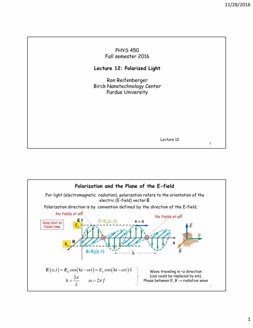
For light (electromagnetic radiation), polarization refers to the orientation of the electric (E-field) vector E.
Polarization direction is by convention defined by the direction of the E-field.
Polarization and the Plane of the E-field
ˆ, cos cos
22
oz t kz t E kz t x
k f
oE E
Eo
Bo
No fields at all!No fields at all!E=Ey(z,t)
B=Bz(z,t)
Snap shot at fixed time
z
Wave traveling in +z direction(cos could be replaced by sin).
Phase between E, B radiative wave2
11/28/2016
2
3
Historical Timeline1669 Bartholinus – describes image doubling properties of calcite
Start of a 150 year odyssey: To explain light, you must explain birefringent properties of calcite!1808 Malus discovers that calcite can modulate brightness of light passing through it.
• Measures light reflected from various surfaces• First to describes light as being “polarized”• Malus’ Law for crossed polarizers: I=Iocos2()
1817 Young realizes light must have a perpendicular component1821 Fresnel claims light must be 100% transverse1828 Nicol cuts thin slab of calcite – makes first transmissive polarizer, produces plane polarized light1928 Land invents a sheet-type dichroic linear polarizer (while an undergrad at Harvard University)
4
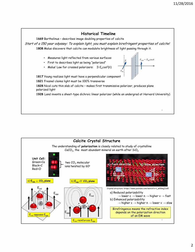
Calcite Crystal StructureThe understanding of polarization is closely related to study of crystalline
CaCO3, the most abundant mineral on earth after SiO2
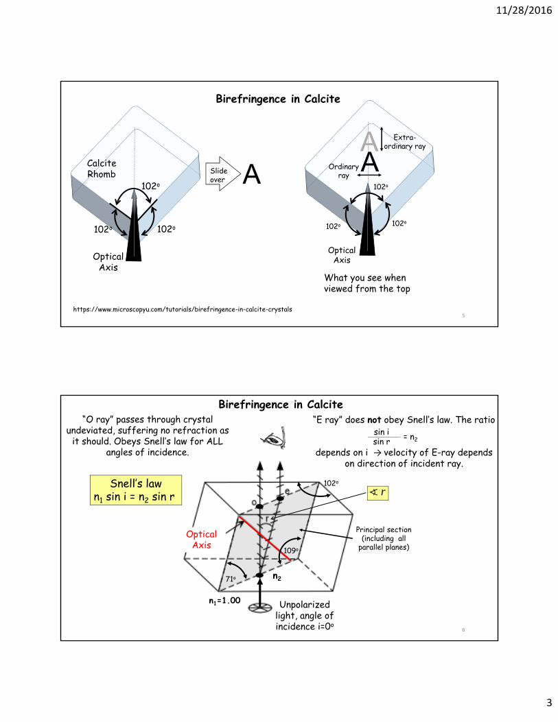
“O ray” passes through crystal undeviated, suffering no refraction as
it should. Obeys Snell’s law for ALL angles of incidence.
Unpolarizedlight, angle of incidence i=0o
Optical Axis
102o
71o
109o
Principal section (including all
parallel planes)
n1=1.00
n2
“E ray” does not obey Snell’s law. The ratio
depends on i → velocity of E-ray depends on direction of incident ray.
sin isin r = n2
Birefringence in Calcite
Snell’s lawn1 sin i = n2 sin r r
11/28/2016
4
7
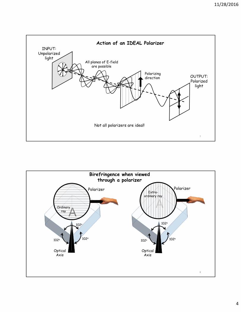
Action of an IDEAL Polarizer
Not all polarizers are ideal!
Polarizing direction
INPUT: Unpolarized
light
OUTPUT: Polarized
light
All planes of E-field are possible
8
A102o
102o102o
Optical Axis
Polarizer
Ordinary ray
102o
102o102o
Optical Axis
A
PolarizerExtra-
ordinary ray
Birefringence when viewed through a polarizer
11/28/2016
5
9
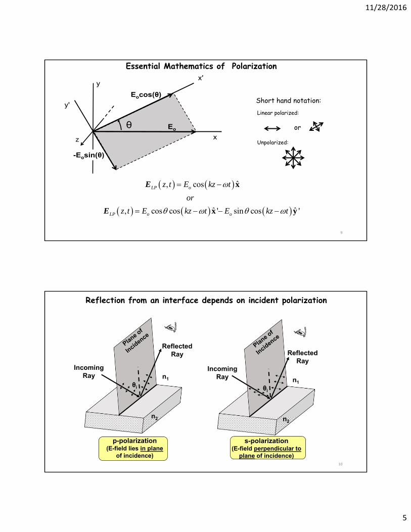
-Eosin(θ)
θx
x'
y'
y
Eo
Eocos(θ)
ˆ, cos
ˆ ˆ, cos cos ' sin cos '
LP o
LP o o
z t E kz t
or
z t E kz t E kz t
x
x y
E
E
Essential Mathematics of Polarization
or
Short hand notation:Linear polarized:
Unpolarized:z
10
Reflection from an interface depends on incident polarization
Incoming Ray
Reflected Ray
θi
p-polarization (E-field lies in plane
of incidence)
n1
n2
s-polarization(E-field perpendicular to
plane of incidence)
Incoming Ray
Reflected Ray
θi
n2
n1
11/28/2016
6
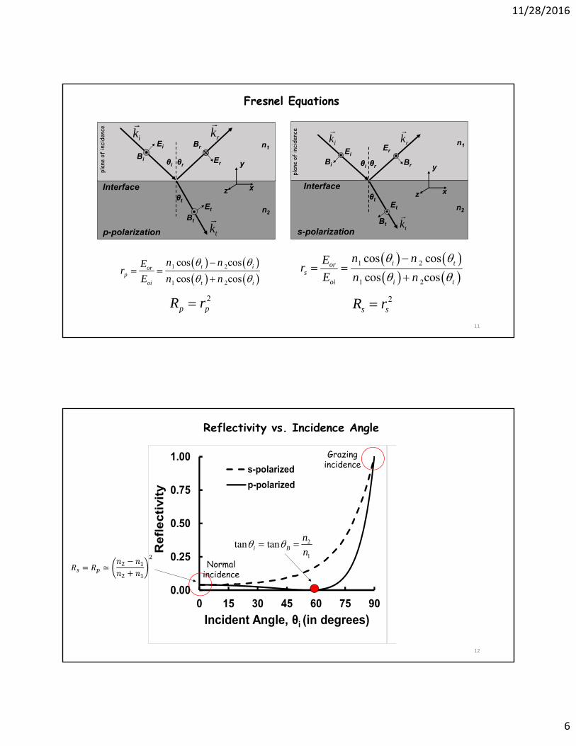
11
n1
n2
ik
rk
tk
θi θr
θt
EiBi Er
Br
EtBt
Interface x
y
z
p-polarization
n1
n2
ik
rk
tk
θi θr
θt
EiBi
Er
Br
Et
Bt
Interfacex
y
z
s-polarization
plan
e of
inci
denc
e
plan
e of
inci
denc
e
1 2
1 2
cos cos
cos cosi tor
soi i t
n nEr
E n n
1 2
1 2
cos cos
cos cost ior
poi t i
n nEr
E n n
2s sR r2
p pR r
Fresnel Equations
12
0.00
0.25
0.50
0.75
1.00
0 15 30 45 60 75 90
Refl
ecti
vit
y
Incident Angle, θi (in degrees)
s-polarized
p-polarized
Grazing incidence
Normal incidence
Reflectivity vs. Incidence Angle
≃
2
1
tan tani B
n
n
11/28/2016
7
13
polarizer
p-polarization
E
Eprism
slit
Na lamp
plane of incidence
i
Measure Brewster’s Angle for Prism
polarizer
s-polarization
E
E
plane of incidence
slit
Na lamp
prism
i
PLUS
Top view Top view
1. Continuously adjust polarizer to block s and pass p2. Continuously adjust prism angle to minimize p3. When intensity is minimum, measure 4. Infer i=B
collimator collimator
14
Phase Shifting Light
ˆ ˆ, cos cosLP ox oyz t E kz t E kz t x + yE
Linearly polarized wave, standard notation:
Phase shifted wave:
ˆ ˆ, cos cosLP ox oyz t E kz t E kz t x + yE'
If =0 or =π, wave is still linearly polarized
ˆ, cosLP oz t E kz t xE
air
glass, n
d 2
ˆ, cosLP oair
z t E d t
xE
2 2ˆ ˆ, cos cos
2ˆcos
21
a
LP o oairg
io
air
las
r
s
n d
z t E d t E d t
E d t
n
x = x
= x
E
BASIC IDEA:
More Generally:
Example: for d=1 m, n=1.5, air=545 nm, then =1.83π
11/28/2016
8
1515
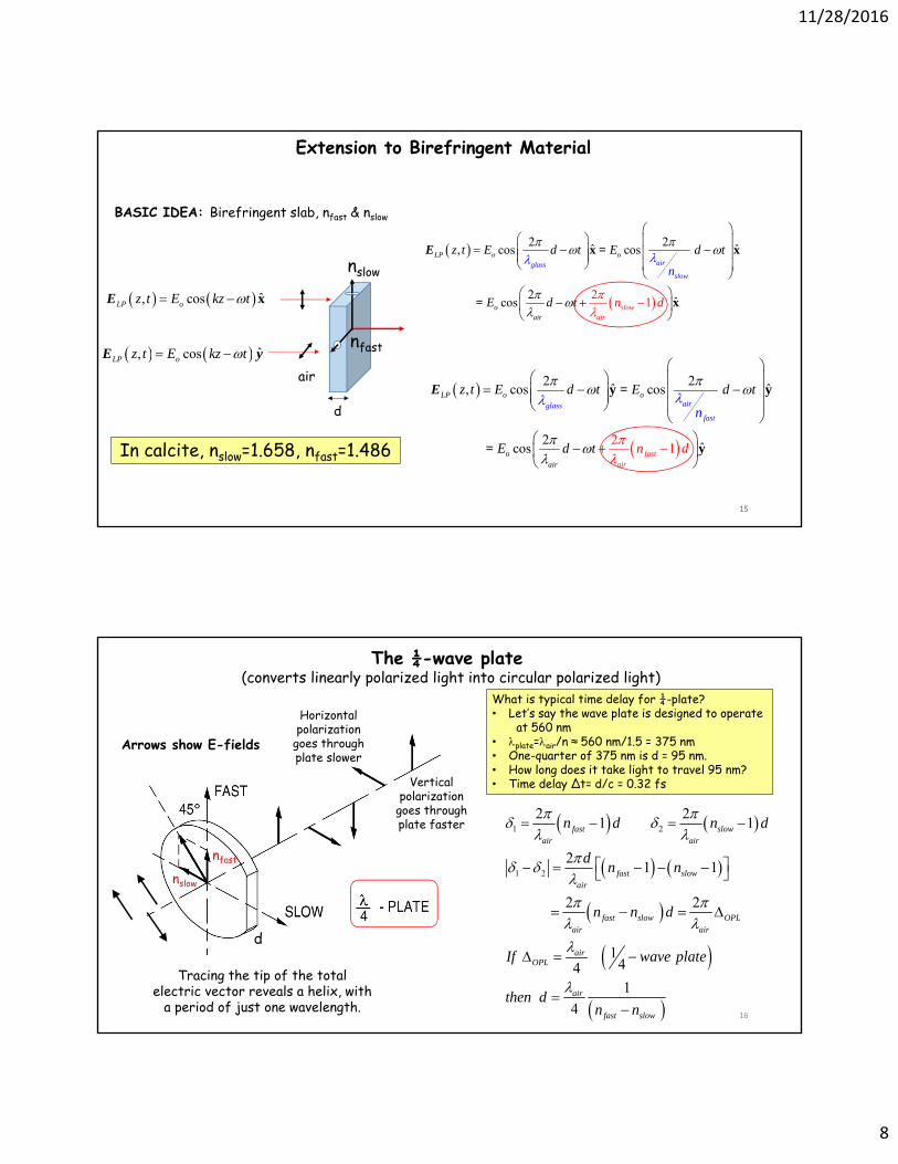
Extension to Birefringent Material
ˆ, cosLP oz t E kz t xE
air
d
2 2ˆ ˆ, cos
2
cos
2ˆc 1os slow
a
Lair
P o o
ir
glass
slo
o
w
air
z t E d t E d t
E d
n
nt d
x = x
= x
E
Birefringent slab, nfast & nslowBASIC IDEA:
nfast
nslow
ˆ, cosLP oz t E kz t E y
2 2ˆ ˆ, cos
2
cos
2ˆc 1os fast
a
Lair
P o o
ir
glass
fas
o
t
air
z t E d t E d t
E d
n
nt d
y = y
= y
E
In calcite, nslow=1.658, nfast=1.486
16
The ¼-wave plate (converts linearly polarized light into circular polarized light)
Vertical polarization
goes through plate faster
Horizontal polarization
goes through plate slower
1 2
1 2
2 21 1
21 1
2 2
1441
4
fast slowair air
fast slowair
fast slow OPLair air
airOPL
air
fast slow
n d n d
dn n
n n d
If wave plate
then dn n
d
nslow
nfast
What is typical time delay for ¼-plate? • Let’s say the wave plate is designed to operate
at 560 nm• plate=air/n ≈ 560 nm/1.5 = 375 nm • One-quarter of 375 nm is d = 95 nm. • How long does it take light to travel 95 nm? • Time delay Δt= d/c = 0.32 fs
Tracing the tip of the total electric vector reveals a helix, with
a period of just one wavelength.
Arrows show E-fields
11/28/2016
9
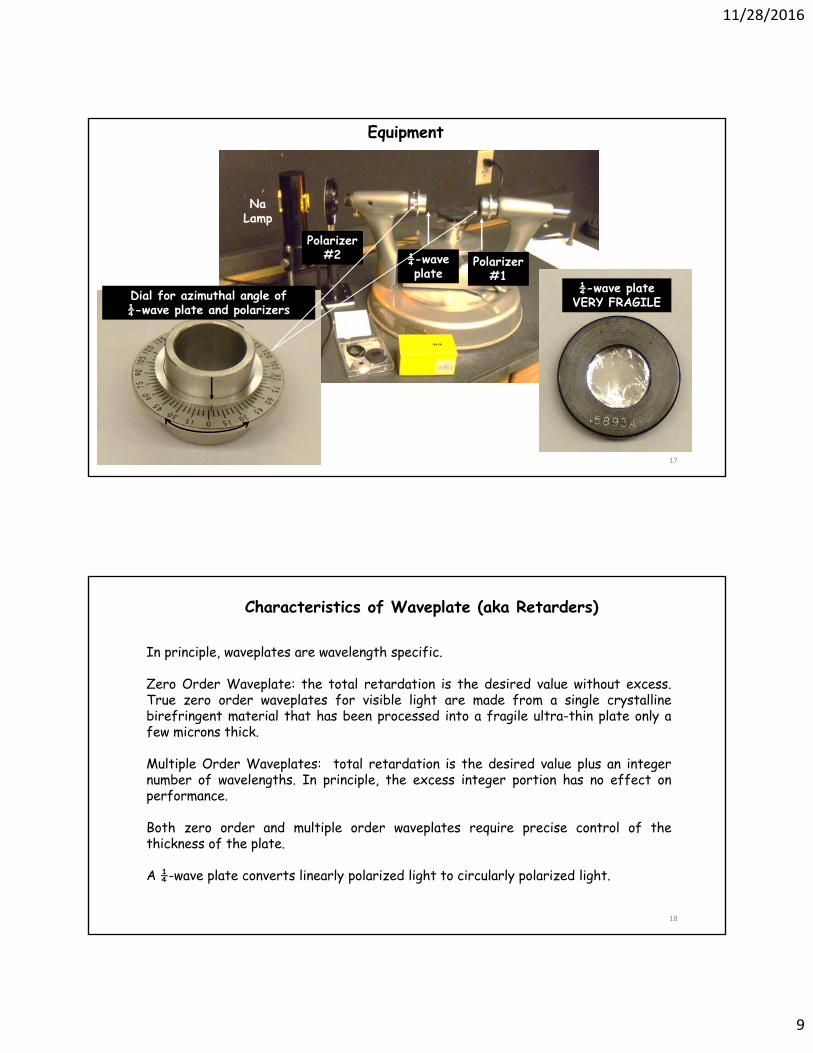
17
Na Lamp
Polarizer #2 ¼-wave
platePolarizer
#1Dial for azimuthal angle of ¼-wave plate and polarizers
¼-wave plate VERY FRAGILE
Equipment
18
In principle, waveplates are wavelength specific.
Zero Order Waveplate: the total retardation is the desired value without excess.True zero order waveplates for visible light are made from a single crystallinebirefringent material that has been processed into a fragile ultra-thin plate only afew microns thick.
Multiple Order Waveplates: total retardation is the desired value plus an integernumber of wavelengths. In principle, the excess integer portion has no effect onperformance.
Both zero order and multiple order waveplates require precise control of thethickness of the plate.
A ¼-wave plate converts linearly polarized light to circularly polarized light.
Characteristics of Waveplate (aka Retarders)
11/28/2016
10
19
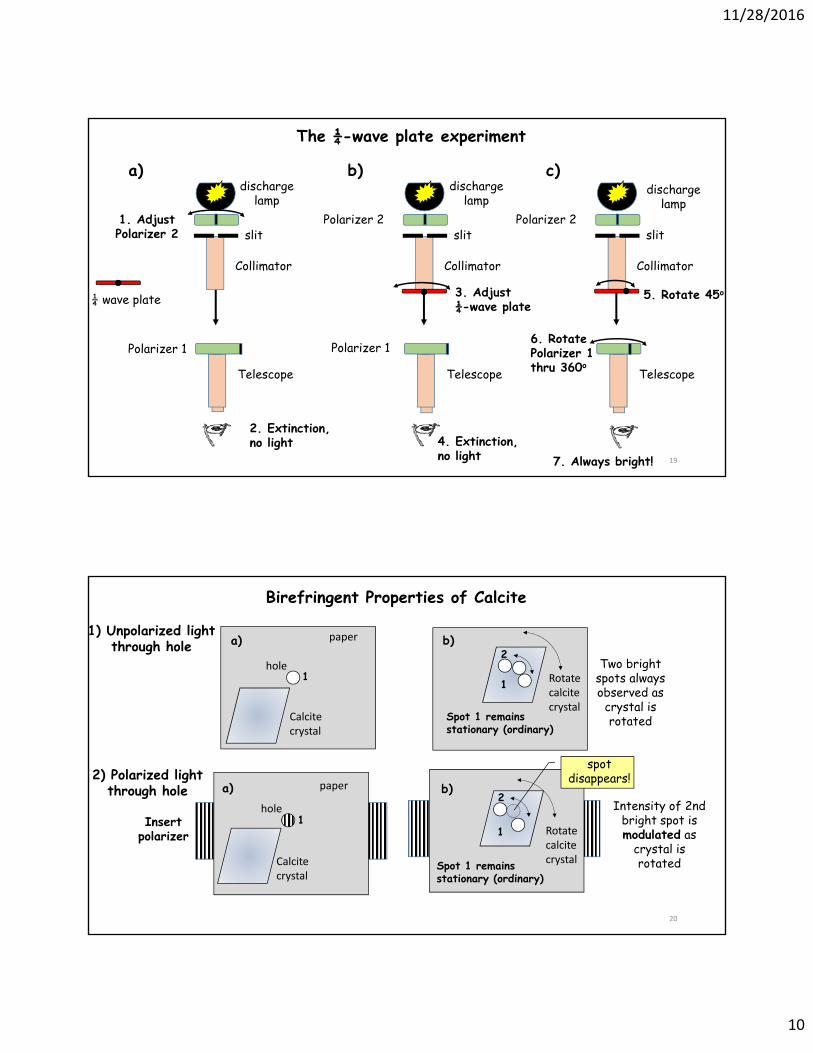
The ¼-wave plate experiment
1. Adjust Polarizer 2 slit
discharge lamp
Polarizer 1
Collimator
Telescope
2. Extinction, no light
Polarizer 2slit
discharge lamp
Polarizer 1
3. Adjust ¼-wave plate
Collimator
Telescope
4. Extinction, no light
Polarizer 2slit
discharge lamp
6. Rotate Polarizer 1 thru 360o
5. Rotate 45o
Collimator
Telescope
7. Always bright!
¼ wave plate
a) b) c)
20
Rotate calcite crystal
Calcite crystal
paper
hole
1) Unpolarized light through hole
Calcite crystal
paper
hole
2) Polarized light through hole
Birefringent Properties of Calcite
Two bright spots always observed as
crystal is rotated
Intensity of 2nd bright spot is modulated as
crystal is rotated
spot disappears!
Rotate calcite crystal
b)
b) a)
a)
1
2
1
2
1
1
Spot 1 remains stationary (ordinary)
Spot 1 remains stationary (ordinary)
Insert polarizer
11/28/2016
11
21
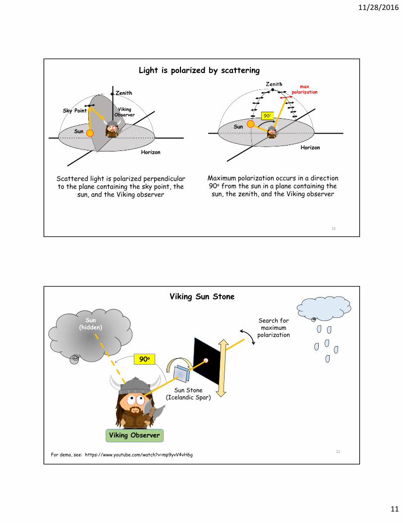
Scattered light is polarized perpendicular to the plane containing the sky point, the
sun, and the Viking observer
Light is polarized by scattering
Horizon
Zenith
Viking Observer
Sun
Sky Point
Maximum polarization occurs in a direction 90o from the sun in a plane containing the sun, the zenith, and the Viking observer
Horizon
Sun
90o
Zenith max polarization
22
Sun Stone (Icelandic Spar)
Viking Observer
Viking Sun Stone
Sun(hidden)
Search for maximum
polarization
For demo, see: https://www.youtube.com/watch?v=mp9yvV4vH6g
90o
11/28/2016
12
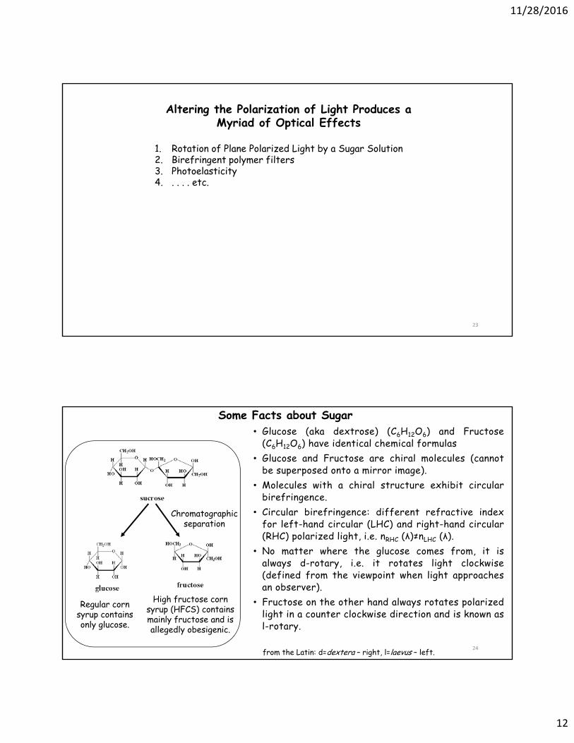
23
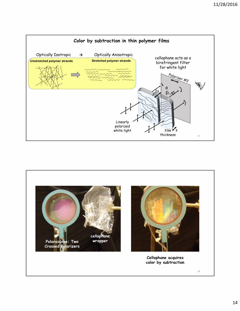
Altering the Polarization of Light Produces a Myriad of Optical Effects
1. Rotation of Plane Polarized Light by a Sugar Solution2. Birefringent polymer filters3. Photoelasticity4. . . . . etc.
24
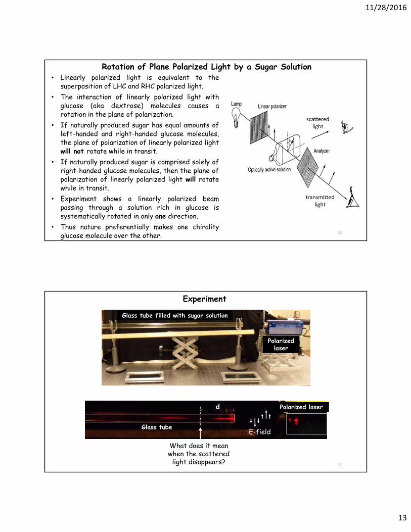
• Glucose (aka dextrose) (C6H12O6) and Fructose(C6H12O6) have identical chemical formulas
• Glucose and Fructose are chiral molecules (cannotbe superposed onto a mirror image).
• Molecules with a chiral structure exhibit circularbirefringence.
• Circular birefringence: different refractive indexfor left-hand circular (LHC) and right-hand circular(RHC) polarized light, i.e. nRHC (λ)≠nLHC (λ).
• No matter where the glucose comes from, it isalways d-rotary, i.e. it rotates light clockwise(defined from the viewpoint when light approachesan observer).
• Fructose on the other hand always rotates polarizedlight in a counter clockwise direction and is known asl-rotary.
from the Latin: d=dextera – right, l=laevus – left.
Some Facts about Sugar
Chromatographic separation
Regular corn syrup contains only glucose.
High fructose corn syrup (HFCS) contains mainly fructose and is allegedly obesigenic.
11/28/2016
13
25
Rotation of Plane Polarized Light by a Sugar Solution• Linearly polarized light is equivalent to the
superposition of LHC and RHC polarized light.• The interaction of linearly polarized light with
glucose (aka dextrose) molecules causes arotation in the plane of polarization.
• If naturally produced sugar has equal amounts ofleft-handed and right-handed glucose molecules,the plane of polarization of linearly polarized lightwill not rotate while in transit.
• If naturally produced sugar is comprised solely ofright-handed glucose molecules, then the plane ofpolarization of linearly polarized light will rotatewhile in transit.
• Experiment shows a linearly polarized beampassing through a solution rich in glucose issystematically rotated in only one direction.
• Thus nature preferentially makes one chiralityglucose molecule over the other.


![a · w o o . SPDC HWP (half wave plate) cos O sin O Beam displacer 410 nrn Kitagawa et al. Nature Comm. '12 0.5 Lattice position BDl)DfHìHl] sin O cos O . Asboth and HO, PRB 88 12306](https://static.documents.pub/doc/80x56/5ed172374b59f12073263b55/a-w-o-o-spdc-hwp-half-wave-plate-cos-o-sin-o-beam-displacer-410-nrn-kitagawa.jpg)


