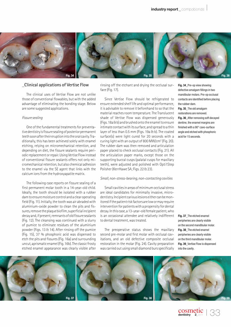
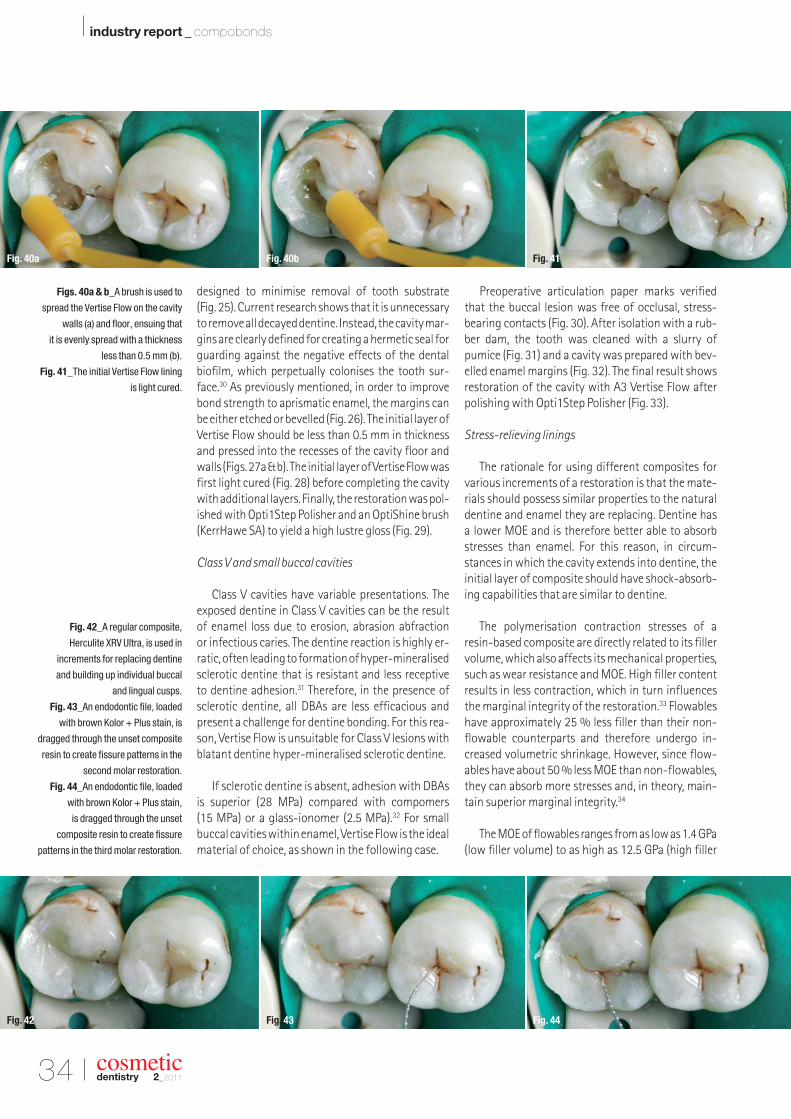
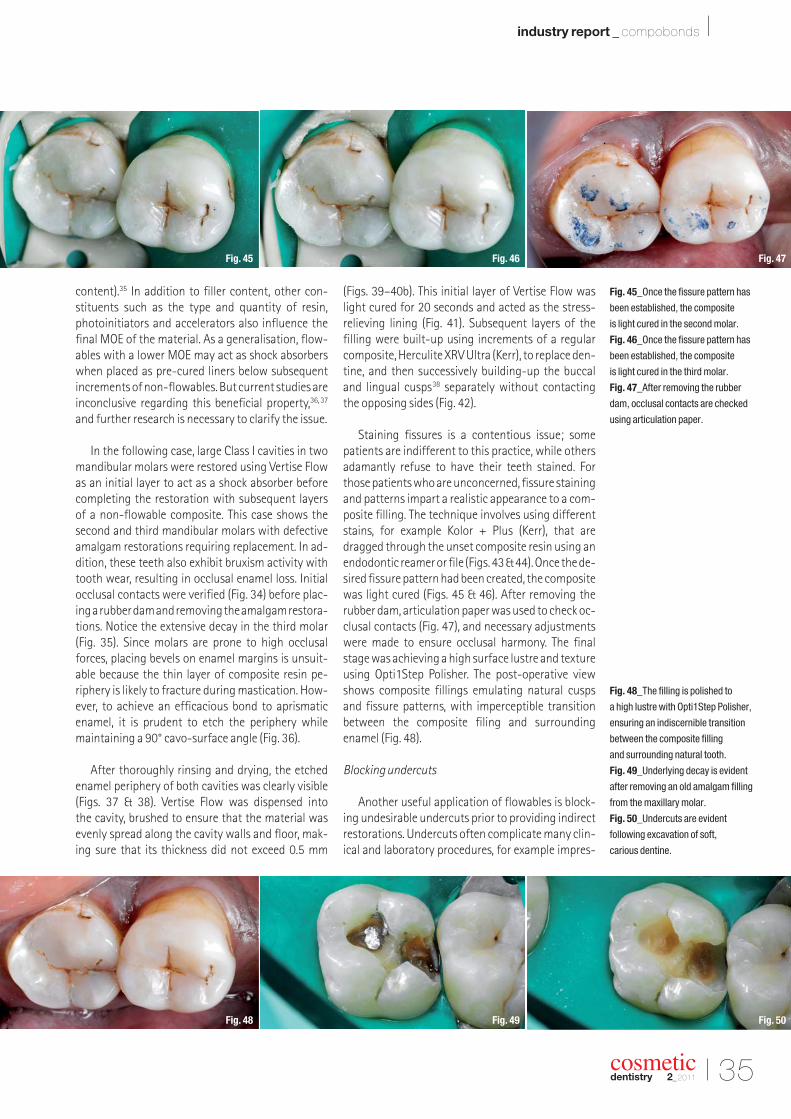
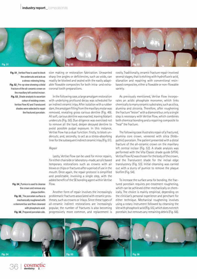
cosmetic dentistry _ beauty & science | MICD Computer-guided occlusal force management | research Investigation of enamel following bleaching | industry report Compobond: Evolution of a new restorative dental material 2 2011 issn 1616-7390 Vol. 5 • Issue 2/2011
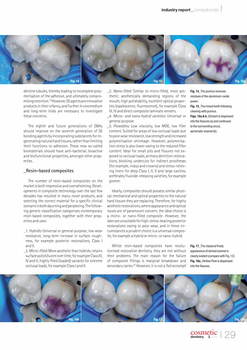
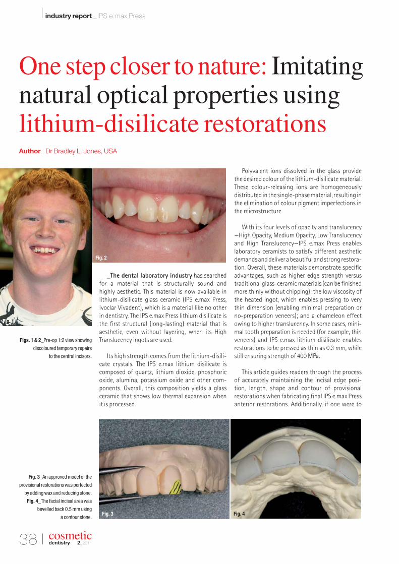
Transcript
cosmeticdentistry _ beauty & science
| MICDComputer-guided occlusalforce management
| researchInvestigation of enamelfollowing bleaching
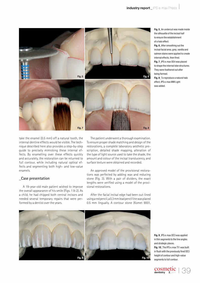
| industry reportCompobond: Evolution of a newrestorative dental material
22011
issn 1616-7390 Vol. 5 • Issue 2/2011
MiCD ad '11-A4.indd 1 4/14/11 5:37:27 PM
I 03
editorial _ cosmetic dentistry I
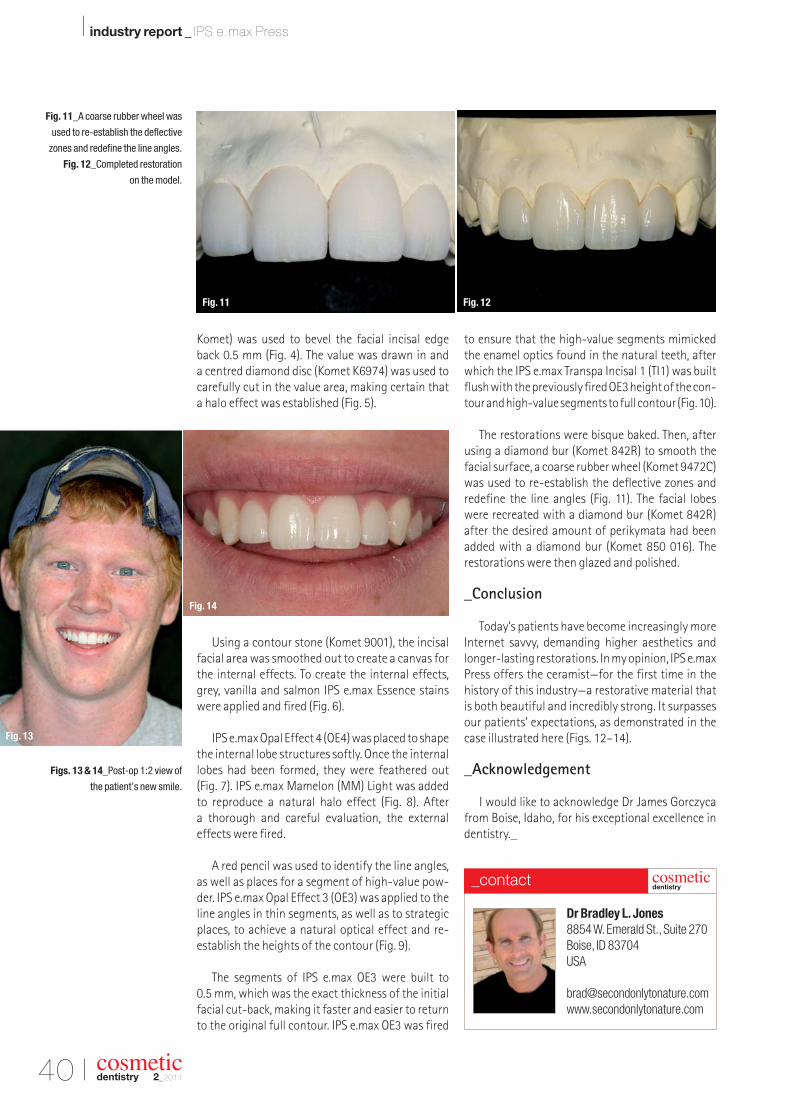
cosmeticdentistry 2_2011
_Welcome to this year’s second issue of cosmetic dentistry! I hope you enjoyed our first issue. All editions of cosmeticdentistryare available online at www.dental-tribune.comat no charge.
With the rapid development of global information technology, knowledge has becomemuch more accessible to everyone keen to acquire it. Online continuing education (CE) programmes are quite popular now in most countries, as it is an easy-to-access and afford-able mode for CE. Global online CE programmes are gaining popularity amongst young generations. However, CE accreditation systems have yet to become mandatory in most Asiancountries. There are various online CE models, including text lectures, slide shows, recordedmovies and live web seminars—webinars. Online study clubs, such as the Dental Tribune StudyClub (www.dtstudyclub.com), and forums are very popular for sharing knowledge and skillsin dentistry.
In February 2011, I travelled to Chicago to participate in the International Federation of Esthetic Dentistry (IFED) general assembly and executive council meeting. I am pleased to announce here that the general assembly unanimously passed the resolution of the execu-tive committee to start a free e-learning system through the IFED website (www.ifed.org). Furthermore, I was nominated as project coordinator. Once the project has been completed,I believe it will help many young professionals to acquire quality aesthetic dentistry edu -cation free of charge. As the coordinator, I am now working at developing professional linksamongst various aesthetics magazines and journals around the world, and am seeking quality articles/clinical cases from authors and clinicians for our e-learning section. I inviteall of you to share your knowledge and skills for better patient care around the world.
For this issue of cosmetic dentistry, we have selected various clinical articles for you andhope they will help to advance your clinical excellence. Enjoy!
Yours faithfully,
Dr Sushil KoiralaEditor-in-ChiefPresident Vedic Institute of Smile Aesthetics (VISA)Kathmandu, Nepal
Dear Reader,
Dr Sushil Koirala
Editor-in-Chief
cosmeticdentistry 2_201104 I
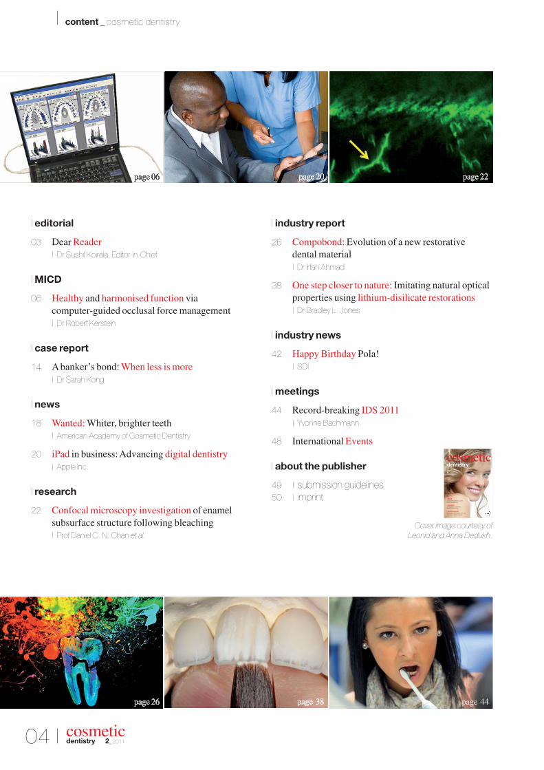
I content _ cosmetic dentistry
page 44
I editorial
03 Dear Reader| Dr Sushil Koirala, Editor-in-Chief
I MICD
06 Healthy and harmonised function via computer-guided occlusal force management| Dr Robert Kerstein
I case report
14 A banker’s bond: When less is more| Dr Sarah Kong
I news
18 Wanted: Whiter, brighter teeth| American Academy of Cosmetic Dentistry
20 iPad in business: Advancing digital dentistry| Apple Inc.
I research
22 Confocal microscopy investigation of enamel subsurface structure following bleaching| Prof Daniel C. N. Chan et al.
I industry report
26 Compobond: Evolution of a new restorative dental material| Dr Irfan Ahmad
38 One step closer to nature: Imitating natural opticalproperties using lithium-disilicate restorations| Dr Bradley L. Jones
I industry news
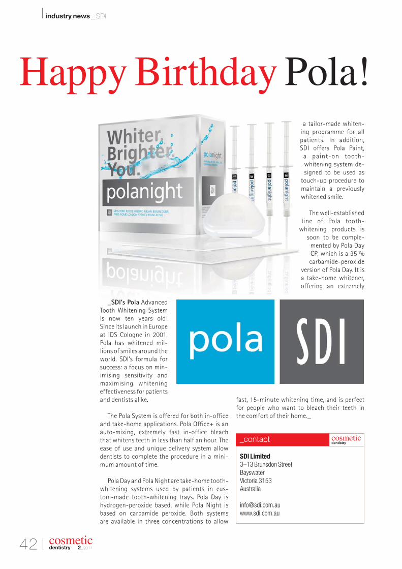
42 Happy Birthday Pola!| SDI
I meetings
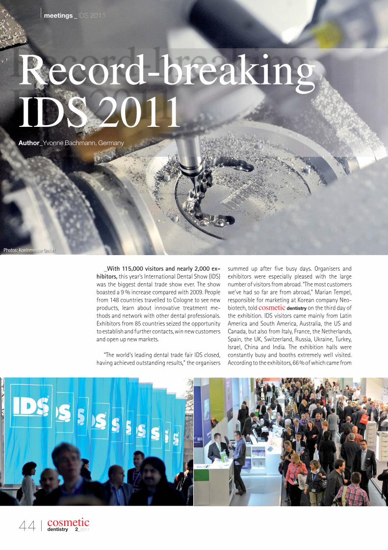
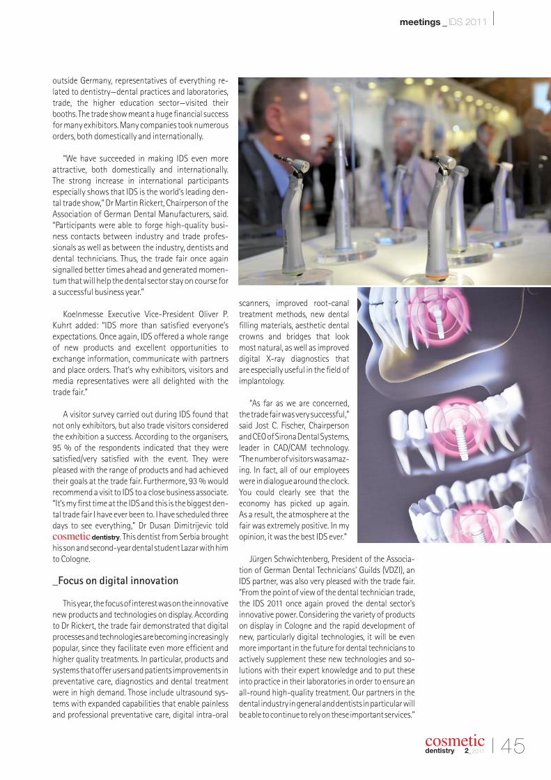
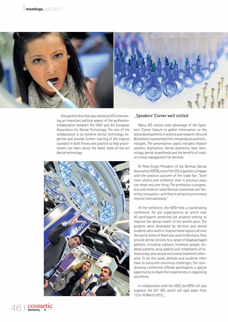
44 Record-breaking IDS 2011| Yvonne Bachmann
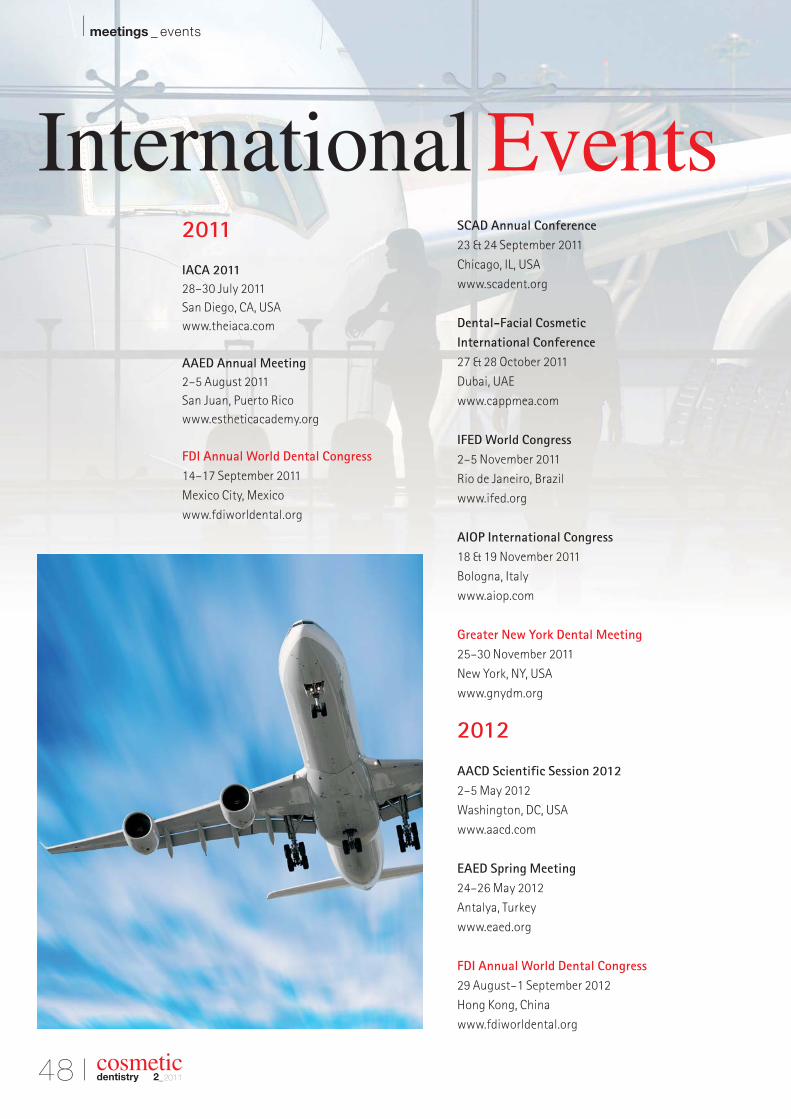
48 International Events
I about the publisher
49 | submission guidelines50 | imprint
Cover image courtesy of
Leonid and Anna Dedukh.
cosmeticdentistry _ beauty & science
| MICDComputer-guided occlusalforce management
| researchInvestigation of enamelfollowing bleaching
| industry reportCompobond: Evolution of a newrestorative dental material
22011
issn 1616-7390 Vol. 5 • Issue 2/2011
for the fourth year in a row, dental tribune study club hosts its annual c.e.symposia at the gnydm, offering four days of focused lectures in variousareas of dentistry. find us on the exhibition floor!
each day will feature a variety of presentations on topics, which will be ledby experts in that field. Participants will earn ADA CerP Ce credits for eachlecture they attend. DtsC is the official online education partner of gnYDM.
free for registered gnydm attendees, but Pre-registration is recommended.For more information, please contact Julia e. wehkamp, C.e. Director, Dental tribune study ClubPhone: (416) 907-9836, Fax: (212) 244-7185, e-mail: [email protected]
Please see Program details under www.dtstudyclub.com/gnydm
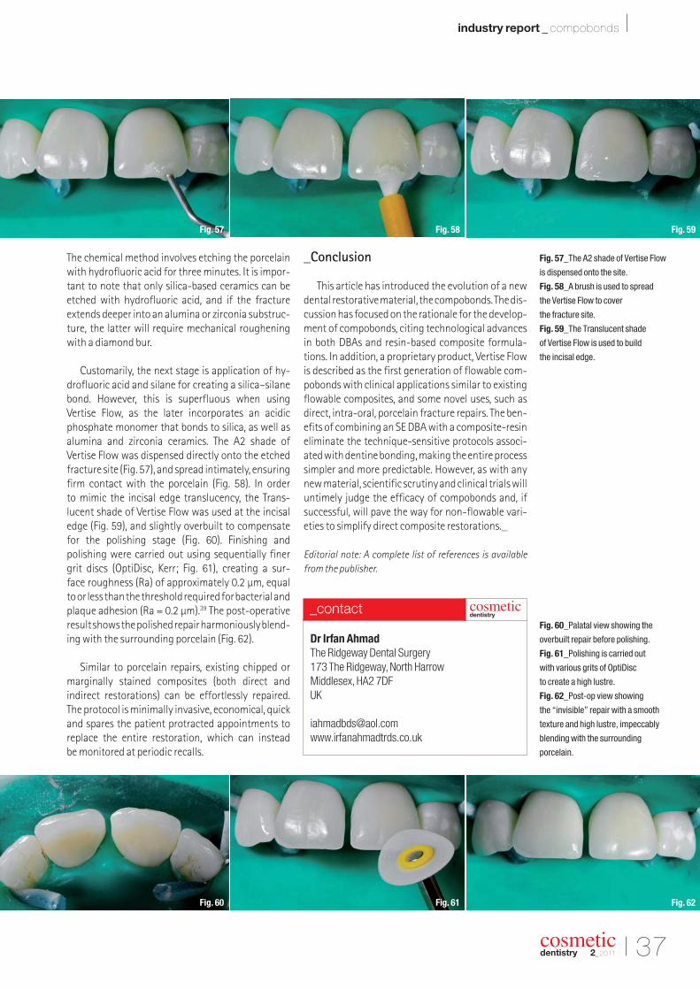
ANNUAL DENTAL TRIBUNE STUDY CLUB
SYMPOSIA AT THE GNYDM
SUNDAY, NOVEMBER 27
10:00 - 11:00 DR. HOWARD GLAZERGIOMERS: NEW GIANTS OF MI DENTISTRY
11:15 - 12:15 DR. SHAMSHUDIN KHERANICOMPREHENSIVE DENTISTRY USING DIGITAL IMPRESSION TECHNOLOGY
12:45 - 1:45 DR. RON KAMINERMINIMALLY INVASIVE DENTISTRY: TIPS AND TRICKS TO MAXIMIZESUCCESS
2:00 - 3:00 DR. LOUIS MALCMACHERTHE HOTTEST TOPICS IN DENTISTRY
3:15 - 4:15 TBATECHNOLOGY TO IMPROVE YOUR CARIES MANAGEMENT
4:30 - 5:30 DR. GEORGE FREEDMANEVOLVING CONSERVATIVE RESTORATIONS
MONDAY, NOVEMBER 28
10:00 - 11:00 DR. FAY GOLDSTEPWHAT PATIENTS WANT… WHAT DENTISTS WANT: EASY, HEALTHY DENTISTRY!
11:15 - 12:15 DR. SHAMSHUDIN KHERANILASER DENTISTRY OVERVIEW WITH AN UPDATE ON CLOSED FLAP OSSEOUS
12:45 - 1:45 DR. LARRY EMMOTTREMEMBER WHEN “E” WAS JUST A LETTER? USE E-SERVICES TO IMPROVE PATIENT CARE AND INCREASE PROFITABILITY
2:00 - 3:00 DR. GEORGE FREEDMAN AND DR. FAY GOLDSTEPDIODE LASERS AND RESTORATIVE DENTISTRY
3:15 - 4:15 DR. DAMIEN MULVANYWHY VIEW YOUR 3D PATIENTS WITH 2D IMAGES? A COMMON SENSE APPROACH TO 3D IMAGING IN THE GENERAL PRACTICE
4:30 - 5:30 DR. MARTY JABLOWUNDERSTANDING THE ADVANCES IN SELF-ADHESIVE TECHNLOGYAND HOW TO INCORPORATE THEM INTO YOUR RESTORATIVEPRACTICE
TUESDAY, NOVEMBER 29
12:45 - 1:45 DR. GEORGE FREEDMAN AND DR. FAY GOLDSTEPTHE DIODE LASER: THE ESSENTIAL SOFT TISSUE HANDPIECE
WEDNESDAY, NOVEMBER 30
11:20 - 12:20 DR. GEORGE FREEDMAN AND DR. PAT ROETZERCEMENTING ALUMINA AND ZIRCONIA RESTORATIONS
12:30 - 5:00 OSSEO SUMMIT
DR. DAVID HOEXTER, ALONG WITH VARIOUS IMPLANT EXPERTSTHE 2ND ANNUAL OSSEO UNIVERSITY SUMMIT: REVOLUTIONARY IMPLANT DESIGN UNVEILED
THIS PROGRAM IS SUBJECT TO CHANGE
NOVEMBER 27TH - 30TH, 2011, STARTING AT 10:00 AM DAILYwww.DTStudyClub.com
freeentrance
earn 20 c.e. credits
register now: www.gnydm.com
DTSC_GNYDM_280x390:Layout 1 17.06.11 10:05 Seite 1
06 I
I MICD _ occlusal force management
_The minimally invasive (MI) concept was ini-tially introduced in physical medicine and adoptedinto dental medicine in the early 1970s with the application of diamine silver fluoride to teeth.1 Thiswas followed by the development of preventiveresin restorations (sealants) in the 1980s2 and theatraumatic restorative treatment (ART) approach3
with Carisolv (MediTeam) in the 1990s.4 Since its inception, the focus of MI dentistry has been
caries detection and treatment.5 It hasnot yet been comprehensively
adopted in other fields of dental me dicine; however,
the comprehensive con-cept of minimally in-vasive cosmetic den-tistry (MICD) and itstreatment protocolwere introduced in2009 with the basicaim of a clinicianeffecting optimumclinical ther apeu-tic improvements in
smile enhancement,while performing cor-
rective procedures thatrequire as little clinical inter-
vention as possible.6 Additionalguidelines for MICD treatment are:
_the adoption of the “Do No Harm” philosophy tomaximise possible preservation of healthy oraltissues;
_the proper selection of appropriate dental mate-rials;
_the use of supportive procedure methodologiesthat offer clinicians an “evidence-based” treat-ment approach that will reliably improve treat-ment outcomes.
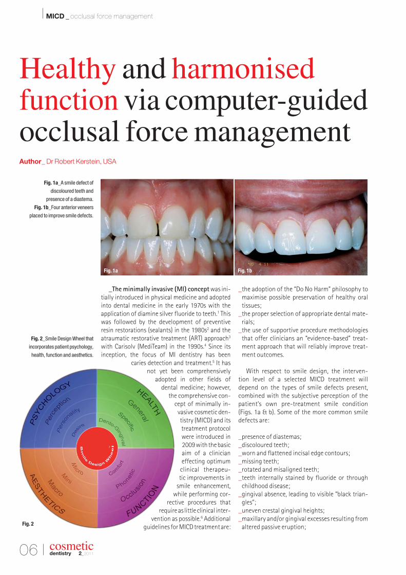
With respect to smile design, the interven-tion level of a selected MICD treatment will depend on the types of smile defects present, com bined with the subjective perception of the patient’s own pre-treatment smile condition (Figs. 1a & b). Some of the more common smile defects are:
_presence of diastemas;_discoloured teeth;_worn and flattened incisal edge contours;_missing teeth;_rotated and misaligned teeth;_teeth internally stained by fluoride or through
childhood disease;_gingival absence, leading to visible “black trian-
gles”;_uneven crestal gingival heights;_maxillary and/or gingival excesses resulting from
altered passive eruption;
cosmeticdentistry 2_2011
Fig. 1a_A smile defect of
discoloured teeth and
presence of a diastema.
Fig. 1b_Four anterior veneers
placed to improve smile defects.
Fig. 2_Smile Design Wheel that
incorporates patient psychology,
health, function and aesthetics.
Healthy and harmonised function via computer-guidedocclusal force managementAuthor_ Dr Robert Kerstein, USA
Fig. 1bFig. 1a
Fig. 2
_malocclusion according to Angle’s classification;and
_reverse smile curve.
Contemporary aesthetic dentistry can correctmost of these defects utilising a simple, compre-hensive, MI approach that places equal empha-sis on patient psychology, health, function and aesthetics. Each of these aspects of treatment con -sideration can be best analysed using the decision-making system of the Smile Design Wheel, which includes each individual aspect as a continuum (Fig. 2).6
_Smile design with all-ceramic, partial coverage restorations
All-ceramic, partial coverage adhesive resto -ration (porcelain veneers, inlays and onlays) is considered one of the MI treatment options inMICD treatment as opposed to placing completecoverage restorations (full crowns) that requiresignificantly more tooth preparation. In certainsituations, no-preparation veneers may be placedbut only if the final aesthetics will not be compro-mised by the added thickness of the labio-lingualrestorative material that a no-preparation veneercreates.
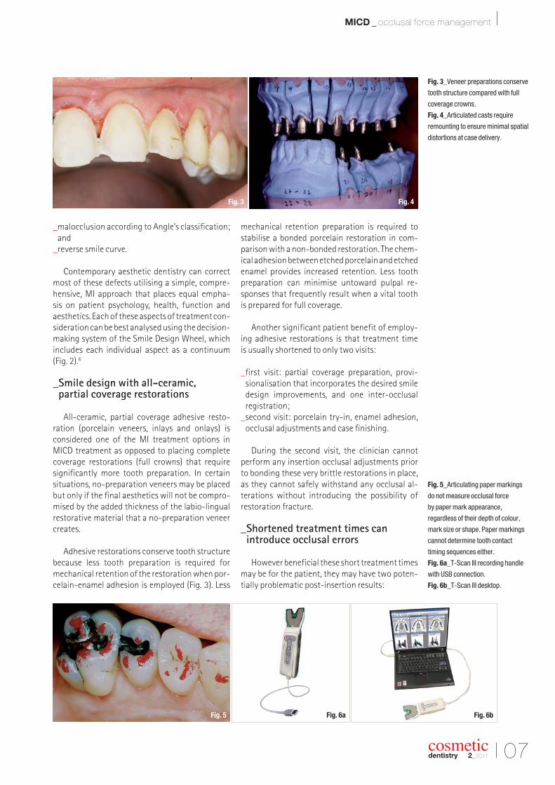
Adhesive restorations conserve tooth structurebecause less tooth preparation is required for mechanical retention of the restoration when por -celain-enamel adhesion is employed (Fig. 3). Less
mechanical retention preparation is required to stabilise a bonded porcelain restoration in com-parison with a non-bonded restoration. The chem-ical adhesion between etched porcelain and etchedenamel provides increased retention. Less toothpreparation can minimise untoward pulpal re-sponses that frequently result when a vital tooth is prepared for full coverage.
Another significant patient benefit of employ-ing adhesive restorations is that treatment time is usually shortened to only two visits:
_first visit: partial coverage preparation, provi -sionalisation that incorporates the desired smile design improvements, and one inter-occlusal registration;
_second visit: porcelain try-in, enamel adhesion,occlusal adjustments and case finishing.
During the second visit, the clinician cannot perform any insertion occlusal adjustments prior to bonding these very brittle restorations in place, as they cannot safely withstand any occlusal al -terations without introducing the possibility ofrestoration fracture.
_Shortened treatment times can introduce occlusal errors
However beneficial these short treatment timesmay be for the patient, they may have two poten-tially problematic post-insertion results:
Fig. 3_Veneer preparations conserve
tooth structure compared with full
coverage crowns.
Fig. 4_Articulated casts require
remounting to ensure minimal spatial
distortions at case delivery.
Fig. 5_Articulating paper markings
do not measure occlusal force
by paper mark appearance,
regardless of their depth of colour,
mark size or shape. Paper markings
cannot determine tooth contact
timing sequences either.
Fig. 6a_T-Scan III recording handle
with USB connection.
Fig. 6b_T-Scan III desktop.
I 07
MICD _ occlusal force management I
cosmeticdentistry 2_2011
Fig. 6a Fig. 6bFig. 5
Fig. 4Fig. 3
08 I
I MICD _ occlusal force management
cosmeticdentistry 2_2011
_patient discomfort owing to difficult occlusion initially post-insertion;
_potentially shortened restoration lifespan.
These sequelae result from the lack of repeatedinter-occlusal remounts, which conventionalprostho dontic cases commonly undergo. Re-mounting at metal try-in, porcelain bisque try-inand possibly once more prior to prosthesis instal-lation greatly improves the accuracy of the truemaxillo-mandibular, inter-arch spatial relation-ships (Fig. 4). This reduces the number of occlusaladjustments required at insertion, thereby pre-serving restorative material thickness and restora-tion strength.
Adhesive restorations are almost incapable ofbeing reliably remounted. Because of the minimalpreparation configuration of partial coverage,non-bonded, all-ceramic restorations, they areunstable on their supporting teeth. Mousses,waxes, silicone putty, injected impression materi-als and impression tray seating can all easily dis-lodge the non-bonded restorations from their sup-porting teeth when taking inter-occlusal records.The movement of non-bonded restorations canalso occur during a “pick-up” or transfer impres-sion. The instability of non-bonded restorationscomplicates all aspects of any remounting pro -cedure greatly.
Without the series of laboratory remounts that a cemented prosthesis often undergoes, theall- ceramic restoration is susceptible to signifi-cant spatial misalignment and excessive occlu-sal force that can go undetected clinically untilafter the insertion has been started. This lack ofproper detection of the location of problematicforce is worsened by the fact that articulating paper markings do not measure the occlusalforces or the occlusal contact timing sequence in any quantifiable way, regardless of the falseand often-advocated paper marking beliefs (Fig. 5).7–16
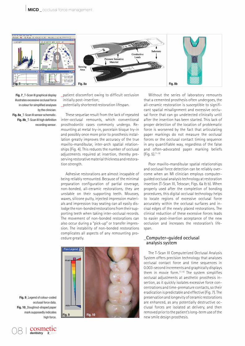
Poor maxillo-mandibular spatial relationships and occlusal force detection can be reliably over-come when an MI clinician employs computer-guided occlusal analysis technology at restorationinsertion (T-Scan III, Tekscan; Figs. 6a & b). Whenproperly used after the completion of bonding procedures, this digital occlusal technology helpsto locate regions of excessive occlusal force accurately within the occlusal surfaces and in-cisal edges of the newly placed restorations. Theclinical reduction of these excessive forces leads to easier post-insertion acceptance of the new occlusion and increases the restoration’s life-span.
_Computer-guided occlusal analysis system
The T-Scan III Computerized Occlusal AnalysisSystem offers precision technology that analysesocclusal contact force and time sequences in 0.003-second increments and graphically displaysthem in movie form.17,18 The system simplifies occlusal adjustments at aesthetic prosthesis in -sertion, as it quickly isolates excessive force con-centrations and time-premature contacts, so theireradication is predictable and effective (Fig. 7). Thepreservation and longevity of ceramic restorationsare enhanced, as any potentially destructive oc-clusal forces are isolated at delivery, and then removed prior to the patient’s long-term use of thenew smile design prosthesis.
Fig. 7_T-Scan III graphical display
illustrates excessive occlusal force
in colour for simplified analyses
by the clinician.
Fig. 8a_T-Scan III sensor schematic.
Fig. 8b_T-Scan III high definition
recording sensor.
Fig. 9_Legend of colour-coded
occlusal force data.
Fig. 10_Doughnut-shaped paper
mark supposedly indicates
high force.
Fig. 8a Fig. 8bFig. 7
Fig. 10Fig. 9
I 09
MICD _ occlusal force management I
cosmeticdentistry 2_2011
The occlusal forceand time-sequencedata are relayed to a PC through a high-definition recordingsensor that measurescontact-varying rela-tive force sequential-ly as differing tooth contacts interact atthe occlusal surfaces(Figs. 8a & b). Dur-ing a turbo-mode re -cording, the sensor isscanned 3,000 times per second, resulting in a dynamic movie of changing occlusal forces thatcan be incrementally viewed in a slow-motionplayback.
This dynamic playback separates all the forcevariances into their contact order, while simul -taneously grading their relative occlusal force, sothat a clinician can observe them for diagnosis andpossible treatment. In two or three dimensions, thecontact timing sequence can be played forwards or backwards continuously or in 0.003-second increments, to reveal an occlusal “movie” that describes the occlusal condition.19 In the 3-D play-back view, the force columns change both theirheight and colour designation. In the 2-D contourview, the colour-coded force concentration zonesalter size, shape and colour as the occlusal forceschange (Fig. 7). Warmer colours indicate forcefulcontacts, while darker colours indicate lower forcecontacts (Fig. 9).
_Limitations of articulating paper markings
Clinicians routinely employ articulating paperto visualise the presence of occlusal contacts, theirforce and their time simultaneity. They determinewhether contacts are forceful by subjective judge-ment of the paper markings for their supposedforce content.
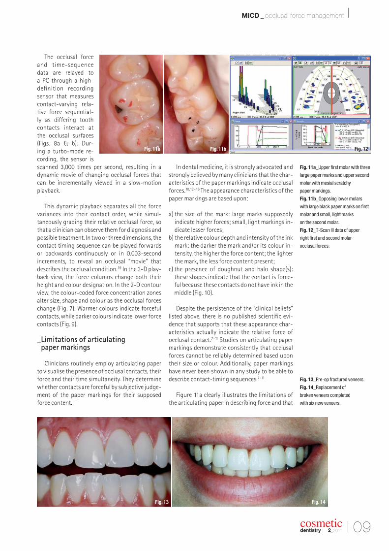
In dental medicine, it is strongly advocated andstrongly believed by many clinicians that the char-acteristics of the paper markings indicate occlusalforces.10,12–16 The appearance characteristics of thepaper markings are based upon:
a) the size of the mark: large marks supposedly indicate higher forces; small, light markings in-dicate lesser forces;
b) the relative colour depth and intensity of the inkmark: the darker the mark and/or its colour in -tensity, the higher the force content; the lighterthe mark, the less force content present;
c) the presence of doughnut and halo shape(s):these shapes indicate that the contact is force-ful because these contacts do not have ink in the middle (Fig. 10).
Despite the persistence of the “clinical beliefs”listed above, there is no published scientific evi-dence that supports that these appearance char -acteristics actually indicate the relative force of occlusal contact.7–11 Studies on articulating papermarkings demonstrate consistently that occlusalforces cannot be reliably determined based upontheir size or colour. Additionally, paper markingshave never been shown in any study to be able to describe contact-timing sequences.7–11
Figure 11a clearly illustrates the limitations ofthe articulating paper in describing force and that
Fig. 11a_Upper first molar with three
large paper marks and upper second
molar with mesial scratchy
paper markings.
Fig. 11b_Opposing lower molars
with large black paper marks on first
molar and small, light marks
on the second molar.
Fig. 12_T-Scan III data of upper
right first and second molar
occlusal forces.
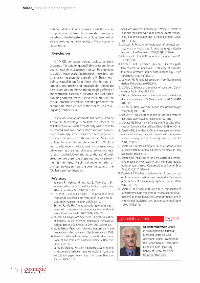
Fig. 13_Pre-op fractured veneers.
Fig. 14_Replacement of
broken veneers completed
with six new veneers.
Fig. 14Fig. 13
Fig. 12Fig. 11bFig. 11a
10 I
I MICD _ occlusal force management
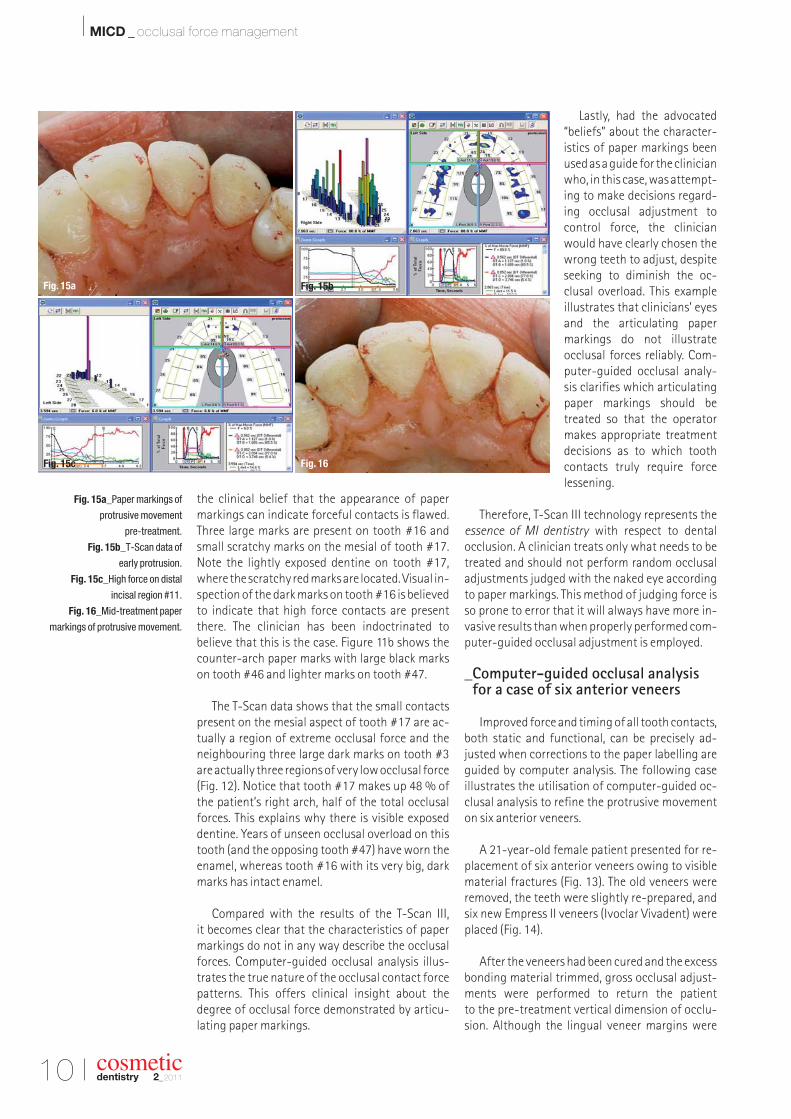
the clinical belief that the appearance of papermarkings can indicate forceful contacts is flawed.Three large marks are present on tooth #16 andsmall scratchy marks on the mesial of tooth #17.Note the lightly exposed dentine on tooth #17,where the scratchy red marks are located. Visual in-spection of the dark marks on tooth #16 is believedto indicate that high force contacts are presentthere. The clinician has been indoctrinated to believe that this is the case. Figure 11b shows thecounter-arch paper marks with large black markson tooth #46 and lighter marks on tooth #47.
The T-Scan data shows that the small contactspresent on the mesial aspect of tooth #17 are ac -tually a region of extreme occlusal force and theneighbouring three large dark marks on tooth #3are actually three regions of very low occlusal force (Fig. 12). Notice that tooth #17 makes up 48 % ofthe patient’s right arch, half of the total occlusalforces. This explains why there is visible exposeddentine. Years of unseen occlusal overload on thistooth (and the opposing tooth #47) have worn theenamel, whereas tooth #16 with its very big, darkmarks has intact enamel.
Compared with the results of the T-Scan III, it becomes clear that the characteristics of papermarkings do not in any way describe the occlusalforces. Computer-guided occlusal analysis illus-trates the true nature of the occlusal contact forcepatterns. This offers clinical insight about the degree of occlusal force demonstrated by articu-lating paper markings.
Lastly, had the advocated“beliefs” about the character-istics of paper markings beenused as a guide for the clinicianwho, in this case, was attempt-ing to make decisions regard-ing occlusal adjustment tocontrol force, the clinicianwould have clearly chosen thewrong teeth to adjust, despiteseeking to diminish the oc-clusal overload. This exampleillustrates that clinicians’ eyesand the articulating papermarkings do not illustrate occlusal forces reliably. Com-puter-guided occlusal analy-sis clarifies which articulatingpaper markings should betreated so that the operatormakes appropriate treatmentdecisions as to which toothcontacts truly require forcelessening.
Therefore, T-Scan III technology represents theessence of MI dentistry with respect to dental occlusion. A clinician treats only what needs to betreated and should not perform random occlusaladjustments judged with the naked eye accordingto paper markings. This method of judging force isso prone to error that it will always have more in-vasive results than when properly performed com-puter-guided occlusal adjustment is employed.
_Computer-guided occlusal analysis for a case of six anterior veneers
Improved force and timing of all tooth contacts,both static and functional, can be precisely ad-justed when corrections to the paper labelling areguided by computer analysis. The following case illustrates the utilisation of computer-guided oc-clusal analysis to refine the protrusive movementon six anterior veneers.
A 21-year-old female patient presented for re-placement of six anterior veneers owing to visiblematerial fractures (Fig. 13). The old veneers wereremoved, the teeth were slightly re-prepared, andsix new Empress II veneers (Ivoclar Vivadent) wereplaced (Fig. 14).
After the veneers had been cured and the excessbonding material trimmed, gross occlusal adjust-ments were performed to return the patient to the pre-treatment vertical dimension of occlu-sion. Although the lingual veneer margins were
Fig. 15a_Paper markings of
protrusive movement
pre-treatment.
Fig. 15b_T-Scan data of
early protrusion.
Fig. 15c_High force on distal
incisal region #11.
Fig. 16_Mid-treatment paper
markings of protrusive movement.
cosmeticdentistry 2_2011
Fig. 15c Fig. 16
Fig. 15a Fig. 15b
I 11
MICD _ occlusal force management I
cosmeticdentistry 2_2011
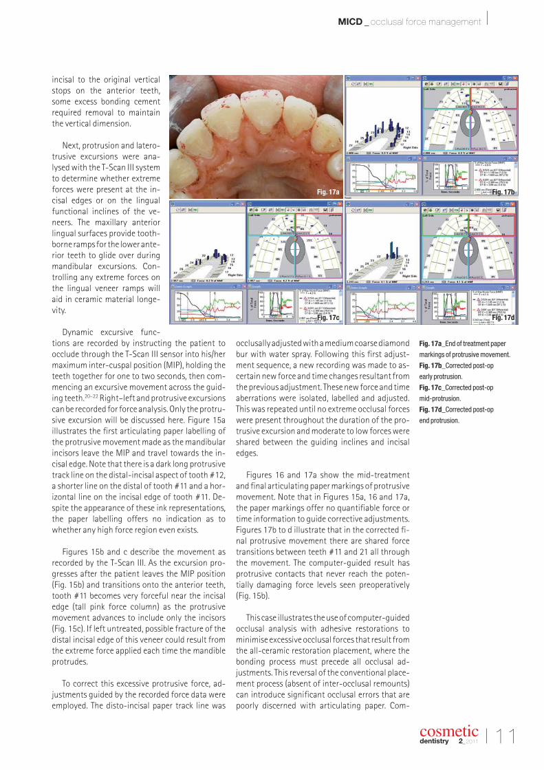
incisal to the original verticalstops on the anterior teeth,some excess bonding cementrequired removal to maintainthe vertical dimension.
Next, protrusion and latero-trusive excursions were ana -lysed with the T-Scan III systemto determine whether extremeforces were present at the in-cisal edges or on the lingualfunctional inclines of the ve-neers. The maxillary anteriorlingual surfaces provide tooth-borne ramps for the lower ante-rior teeth to glide over duringmandibular excursions. Con-trolling any extreme forces onthe lingual veneer ramps willaid in ceramic material longe -vity.
Dynamic excursive func-tions are recorded by instructing the patient to occlude through the T-Scan III sensor into his/hermaximum inter-cuspal position (MIP), holding theteeth together for one to two seconds, then com-mencing an excursive movement across the guid-ing teeth.20–22 Right–left and protrusive excursionscan be recorded for force analysis. Only the protru-sive excursion will be discussed here. Figure 15a illustrates the first articulating paper labelling ofthe protrusive movement made as the mandibularincisors leave the MIP and travel towards the in-cisal edge. Note that there is a dark long protrusivetrack line on the distal-incisal aspect of tooth #12,a shorter line on the distal of tooth #11 and a hor-izontal line on the incisal edge of tooth #11. De-spite the appearance of these ink representations,the paper labelling offers no indication as towhether any high force region even exists.
Figures 15b and c describe the movement asrecorded by the T-Scan III. As the excursion pro-gresses after the patient leaves the MIP position (Fig. 15b) and transitions onto the anterior teeth,tooth #11 becomes very forceful near the incisaledge (tall pink force column) as the protrusivemovement advances to include only the incisors(Fig. 15c). If left untreated, possible fracture of thedistal incisal edge of this veneer could result fromthe extreme force applied each time the mandibleprotrudes.
To correct this excessive protrusive force, ad-justments guided by the recorded force data wereemployed. The disto-incisal paper track line was
occlusally adjusted with a medium coarse diamondbur with water spray. Following this first adjust-ment sequence, a new recording was made to as-certain new force and time changes resultant fromthe previous adjustment. These new force and timeaberrations were isolated, labelled and adjusted.This was repeated until no extreme occlusal forceswere present throughout the duration of the pro-trusive excursion and moderate to low forces wereshared between the guiding inclines and incisaledges.
Figures 16 and 17a show the mid-treatmentand final articulating paper markings of protrusivemovement. Note that in Figures 15a, 16 and 17a,the paper markings offer no quantifiable force ortime information to guide corrective adjustments.Figures 17b to d illustrate that in the corrected fi-nal protrusive movement there are shared forcetransitions between teeth #11 and 21 all throughthe movement. The computer-guided result hasprotrusive contacts that never reach the poten-tially damaging force levels seen preoperatively(Fig. 15b).
This case illustrates the use of computer-guidedocclusal analysis with adhesive restorations tominimise excessive occlusal forces that result fromthe all-ceramic restoration placement, where thebonding process must precede all occlusal ad -justments. This reversal of the conventional place-ment process (absent of inter-occlusal remounts)can introduce significant occlusal errors that arepoorly discerned with articulating paper. Com-
Fig. 17a_End of treatment paper
markings of protrusive movement.
Fig. 17b_Corrected post-op
early protrusion.
Fig. 17c_Corrected post-op
mid-protrusion.
Fig. 17d_Corrected post-op
end protrusion.
Fig. 17d
Fig. 17bFig. 17a
Fig. 17c
12 I
I MICD _ occlusal force management
puter-guided occlusal analysis affords the opera-tor precision, occlusal force isolation and pre-dictable control of restorative occlusal error, whichaids in prolonging the longevity of the all-ceramicrestorations.
_Conclusion
For MICD, computer-guided occlusal analysissystems offer data on quantifiable pressure, forceand contact time sequence that can be employedto guide the occlusal adjustment of the restorationto precise measurable endpoints.2, 3 These end-points establish uniform force distribution, bi -lateral simultaneity and measurable immediate disclusion, and minimise the damaging effect of concentrated, excessive, isolated occlusal force.Avoiding potentially destructive intra-oral use, theoverall prosthetic occlusal scheme preserves theceramic materials utilised in the pro cedure, ensur-ing long-term survival.
Lastly, occlusal adjustments that are guided by T-Scan III technology represent the essence ofMICD because a clinician treats only what needs tobe treated and does not perform random subjec-tive occlusal adjustment based on mere judgementof paper markings with the naked eye. Measuredocclusal force and timing data direct the MI clini-cian to adjust only the locations of excessive force,while leaving the areas of measured low occlusalforce untouched. Cosmetic restorations and toothstructure are therefore preserved and overtreat-ment is minimised. The clinical implementation ofthis technology mirrors the core message of the“Do No Harm” philosophy._
_References1. Yamaga R, Nishino M, Yoshida S, Yokomizo I. Di-
ammine silver fluoride and its clinical application. J Osaka Univ Dent Sch 1972;12:1–20.
2. Houpt M, Fukus A, Eidelman E. The preventive resin(composite resin/sealant) restoration: nine-year re-sults. Quintessence Int 1994;25(3):155–9.
3. Smales RJ. Yip HK. The atraumatic restorative treat-ment (ART) approach for the management of dentalcaries. Quintessence Int 2002;33(6):427–32.
4. Munshi AK, Hegde AM, Shetty PK. Clinical evaluationof Carisolv in the chemico-mechanical removal of carious dentin. J Clin Pediatric Dent 2001;26:49–54.
5. World Dental Federation. Minimal Intervention in themanagement of dental caries. FDI policy statement 2002.
6. Koirala S. Minimally invasive cosmetic dentistry—Concept and treatment protocol. Cosmetic Dentistry2009(4):28–33.
7. Carey JP, Craig M, Kerstein RB, Radke J. Determining a relationship between applied occlusal load and articulation paper mark area. The Open Dentistry Journal 2007;1:1–7.
8. Saad MN, Weiner G, Ehrenberg D, Weiner S. Effects ofload and indicator type upon occlusal contact mark-ings. J Biomed Mater Res B Appl Biomater 2008;85(1):18–22.
9. Millstein P, Maya A. An evaluation of occlusal con-tact marking indicators. A descriptive quantitativemethod. J Am Dent Assoc 2001;132(9):1280–6.
10. Glickman I. Clinical Periodontics. Saunders and Co1979(5):951.
11. Reiber T, Fuhr K, Hartmann H, Leicher D. Recording pat-tern of occlusal indicators. I. Influence of indicatorthickness, pressure, and surface morphology. DtschZahnarztl Z 1989;44(2):90–3.
12. Dawson, PE. Functional occlusion: from TMJ to smiledesign. Mosby, Inc 2007(1):347.
13. McNeil, C. Science and practice of occlusion. Quint -essence Publishing 1997:421.
14. Okeson J. Management of temporomandibular disor-ders and occlusion. CV Mosby and Co 2003(5):416,418, 605.
15. Kleinberg I. Occlusion practice and assessment. KnightPublishing 1991:128.
16. Smukler, H. Equilibration in the natural and restoreddentition. Quintessence Publishing 1991:110.
17. Maness WL. Force movie. A time and force view of oc-clusion. Compend Contin Educ Dent 1989(10):404–8.
18. Kerstein RB, Grundset K. Obtaining measurable bilat-eral simultaneous occlusal contacts with computer-analyzed and guided occlusal adjustments. Quin Int2001;32(1):7–18.
19. Kerstein RB. Tekscan-Computerized Occlusal Analysis.In: Maciel RN. Bruxismo. Editora Artes Medicas Ltda.Sao Paolo, Brazil 2010.
20. Kerstein RB. Reducing chronic massetter and tempo-ralis muscular hyperactivity with computer-guidedocclusal adjustments. Compendium of Contin EducDent 2010;31(7):530–43.
21. Kerstein RB. Combining technologies: A computerizedocclusal analysis system synchronized with a com -puterized electromyography system. Cranio 2004;22(2):96–109.
22. Kerstein RB, Chapman R, Klein M. A comparison ofICAGD (immediate complete anterior guidance devel-opment) to mock ICAGD for symptom reductions inchronic myofascial pain dysfunction patients. Cranio,1997;15(1):21–37.
cosmeticdentistry 2_2011
Dr Robert Kerstein works
in private practice in Boston,
Massachusetts. He was
Assistant Clinical Professor at
the Department of Restorative
Dentistry, Tufts University
School of Dental Medicine
from 1983 to 1998.
cosmeticdentistry
_about the author
Last Name, First Name
Street
Signature Signature
ZIP/City/County
Fon, fax
E-mail
Fax: +49 341 48474-290www.oemus.com
OEMUS MEDIA AGHolbeinstraße 29, 04229 Leipzig, Germany
I would like to subscribe to Dentalzeitung (6 issues peryear) for € 34 including shipping and VAT for German custo-mers, € 36 including shipping and VAT for customers outsideGermany, unless a written cancellation is sent within 14 daysof the receipt of the trial subscription. The subscription will berenewed automatically every year until a written cancellationis sent to OEMUS MEDIA AG, Holbeinstr. 29, 04229 Leipzig,Germany, six weeks prior to the renewal date.
Notice of revocation: I am able to revoke the subscription within 14 daysafter my order by sending a written cancellation to OEMUS MEDIA AG,Holbeinstr. 29, 04229 Leipzig, Germany.
You can also subscribe via www.oemus.com/abo
INNOVATION + INFORMATION
CDE 2/11
I would like to subscribe to ZWP (10 issues per year) for € 70 including shipping and VAT for German customers, € 72 including shipping and VAT for customers outside Ger-many, unless a written cancellation is sent within 14 days ofthe receipt of the trial subscription. The subscription will berenewed automatically every year until a written cancellationis sent to OEMUS MEDIA AG, Holbeinstr. 29, 04229 Leipzig,Germany, six weeks prior to the renewal date.
ZWP_DZ_Kombi_A4_engl 24.06.11 11:59 Seite 1
14 I
I case report _ veneers
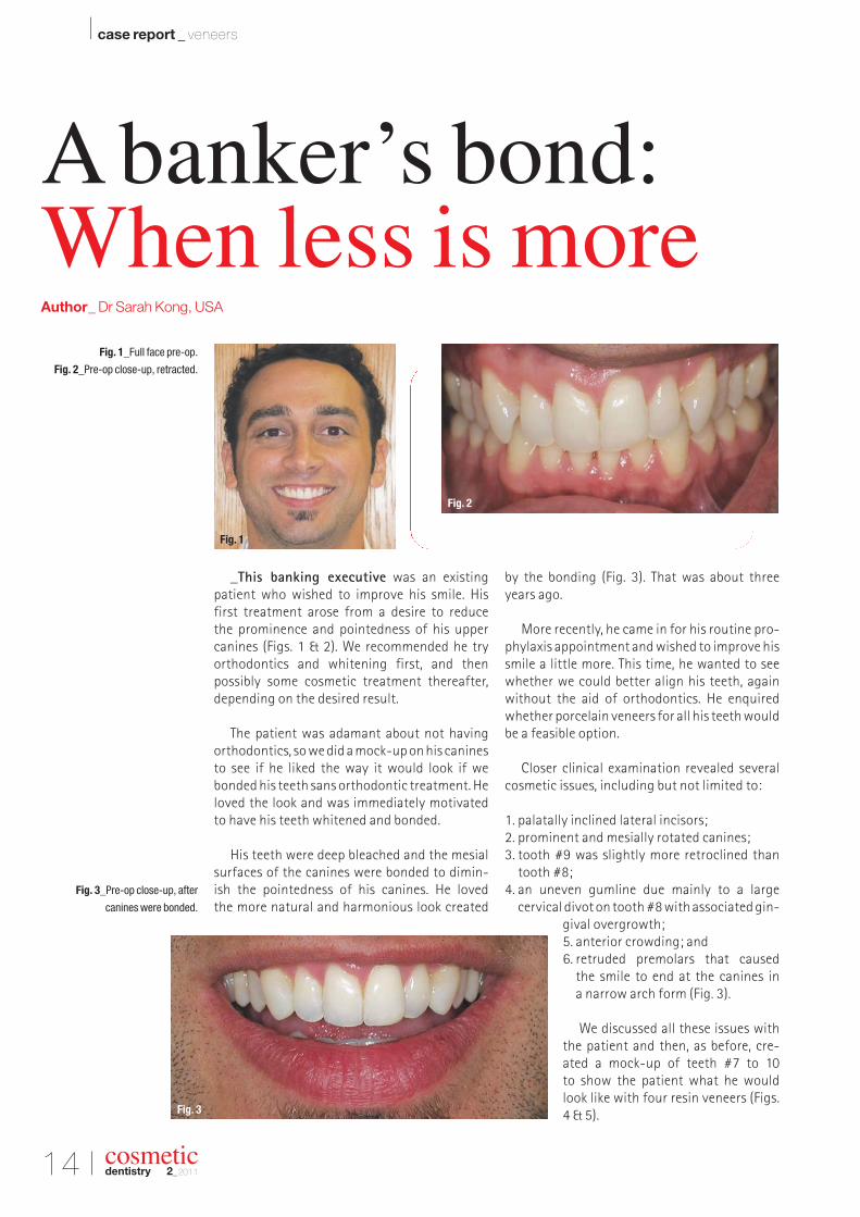
_This banking executive was an existing patient who wished to improve his smile. His first treatment arose from a desire to reduce the prominence and pointedness of his upper canines (Figs. 1 & 2). We recommended he try orthodontics and whitening first, and then possibly some cosmetic treatment thereafter,depending on the desired result.
The patient was adamant about not havingorthodontics, so we did a mock-up on his caninesto see if he liked the way it would look if webonded his teeth sans orthodontic treatment. Heloved the look and was immediately motivatedto have his teeth whitened and bonded.
His teeth were deep bleached and the mesialsurfaces of the canines were bonded to dimin-ish the pointedness of his canines. He loved the more natural and harmonious look created
by the bonding (Fig. 3). That was about threeyears ago.
More recently, he came in for his routine pro-phylaxis appointment and wished to improve hissmile a little more. This time, he wanted to seewhether we could better align his teeth, againwithout the aid of orthodontics. He enquiredwhether porcelain veneers for all his teeth wouldbe a feasible option.
Closer clinical examination revealed severalcosmetic issues, including but not limited to:
1. palatally inclined lateral incisors;2. prominent and mesially rotated canines;3. tooth #9 was slightly more retroclined than
tooth #8;4. an uneven gumline due mainly to a large
cervical divot on tooth #8 with associated gin-gival overgrowth;5. anterior crowding; and6. retruded premolars that caused
the smile to end at the canines in a narrow arch form (Fig. 3).
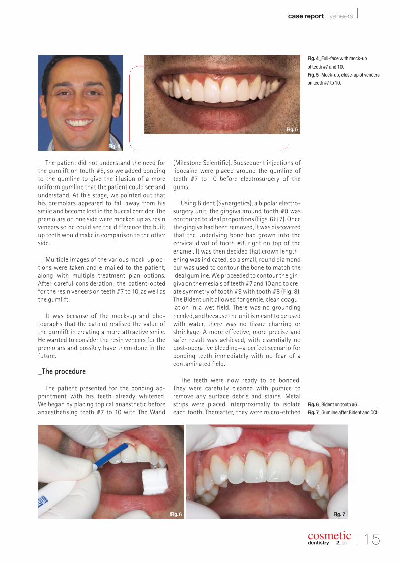
We discussed all these issues withthe patient and then, as before, cre-ated a mock-up of teeth #7 to 10 to show the patient what he wouldlook like with four resin veneers (Figs.4 & 5).
cosmeticdentistry 2_2011
A banker’s bond:When less is moreAuthor_ Dr Sarah Kong, USA
Fig. 1_Full face pre-op.
Fig. 2_Pre-op close-up, retracted.
Fig. 3_Pre-op close-up, after
canines were bonded.
Fig. 1
Fig. 3
Fig. 2
I 15
case report _ veneers I
cosmeticdentistry 2_2011
The patient did not understand the need forthe gumlift on tooth #8, so we added bonding to the gumline to give the illusion of a more uniform gumline that the patient could see andunderstand. At this stage, we pointed out thathis premolars appeared to fall away from hissmile and become lost in the buccal corridor. Thepremolars on one side were mocked up as resinveneers so he could see the difference the builtup teeth would make in comparison to the otherside.
Multiple images of the various mock-up op-tions were taken and e-mailed to the patient,along with multiple treatment plan options. After careful consideration, the patient opted for the resin veneers on teeth #7 to 10, as well asthe gumlift.
It was because of the mock-up and pho -tographs that the patient realised the value ofthe gumlift in creating a more attractive smile.He wanted to consider the resin veneers for thepremolars and possibly have them done in thefuture.
_The procedure
The patient presented for the bonding ap-pointment with his teeth already whitened. We began by placing topical anaesthetic beforeanaesthetising teeth #7 to 10 with The Wand
(Milestone Scientific). Subsequent injections oflidocaine were placed around the gumline ofteeth #7 to 10 before electrosurgery of the gums.
Using Bident (Synergetics), a bipolar electro-surgery unit, the gingiva around tooth #8 wascontoured to ideal proportions (Figs. 6 & 7). Oncethe gingiva had been removed, it was discoveredthat the underlying bone had grown into the cervical divot of tooth #8, right on top of theenamel. It was then decided that crown length-ening was indicated, so a small, round diamondbur was used to contour the bone to match theideal gumline. We proceeded to contour the gin-giva on the mesials of teeth #7 and 10 and to cre-ate symmetry of tooth #9 with tooth #8 (Fig. 8).The Bident unit allowed for gentle, clean coagu-lation in a wet field. There was no groundingneeded, and because the unit is meant to be usedwith water, there was no tissue charring orshrinkage. A more effective, more precise andsafer result was achieved, with essentially nopost-operative bleeding—a perfect scenario forbonding teeth immediately with no fear of acontaminated field.
The teeth were now ready to be bonded. They were carefully cleaned with pumice to remove any surface debris and stains. Metalstrips were placed interproximally to isolateeach tooth. Thereafter, they were micro-etched
Fig. 4_Full-face with mock-up
of teeth #7 and 10.
Fig. 5_Mock-up, close-up of veneers
on teeth #7 to 10.
Fig. 4
Fig. 6 Fig. 7
Fig. 5
Fig. 6_Bident on tooth #6.
Fig. 7_Gumline after Bident and CCL.
16 I
I case report _ veneers
with aluminium oxide to allow for better me-chanical retention. Before the application of a bonding agent (OptiBond Solo Plus Unidose,Kerr), 37 % phosphoric etch was placed andrinsed.
Tooth #8 was bonded first using various lay-ers of composite, starting with a micro-hybrid
(Premise, Kerr/Sybron) and ending with a micro-filled composite (Renamel, COSMEDENT). Thistooth was contoured and polished with a seriesof polishing discs (SHOFU) before proceeding so that the next tooth (#9) could be matched tothis tooth without being bonded to it.
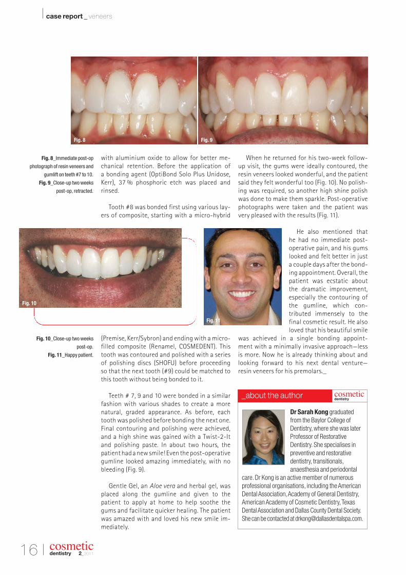
Teeth # 7, 9 and 10 were bonded in a similarfashion with various shades to create a morenatural, graded appearance. As before, eachtooth was polished before bonding the next one.Final contouring and polishing were achieved,and a high shine was gained with a Twist-2-Itand polishing paste. In about two hours, the patient had a new smile! Even the post-operativegumline looked amazing immediately, with nobleeding (Fig. 9).
Gentle Gel, an Aloe vera and herbal gel, wasplaced along the gumline and given to the patient to apply at home to help soothe the gums and facilitate quicker healing. The patientwas amazed with and loved his new smile im -mediately.
When he returned for his two-week follow-up visit, the gums were ideally contoured, theresin veneers looked wonderful, and the patientsaid they felt wonderful too (Fig. 10). No polish-ing was required, so another high shine polishwas done to make them sparkle. Post-operativephotographs were taken and the patient wasvery pleased with the results (Fig. 11).
He also mentioned that he had no immediate post-operative pain, and his gumslooked and felt better in just a couple days after the bond-ing appointment. Overall, thepatient was ecstatic aboutthe dramatic improvement,especially the contouring ofthe gumline, which con-tributed immensely to the final cosmetic result. He alsoloved that his beautiful smile
was achieved in a single bonding appoint-ment with a minimally invasive approach—less is more. Now he is already thinking about andlooking forward to his next dental venture—resin veneers for his premolars._
cosmeticdentistry 2_2011
Fig. 8_Immediate post-op
photograph of resin veneers and
gumlift on teeth #7 to 10.
Fig. 9_Close-up two weeks
post-op, retracted.
Fig. 10_Close-up two weeks
post-op.
Fig. 11_Happy patient.
Dr Sarah Kong graduated
from the Baylor College of
Dentistry, where she was later
Professor of Restorative
Dentistry. She specialises in
preventive and restorative
dentistry, transitionals,
anaesthesia and periodontal
care. Dr Kong is an active member of numerous
professional organisations, including the American
Dental Association, Academy of General Dentistry,
American Academy of Cosmetic Dentistry, Texas
Dental Association and Dallas County Dental Society.
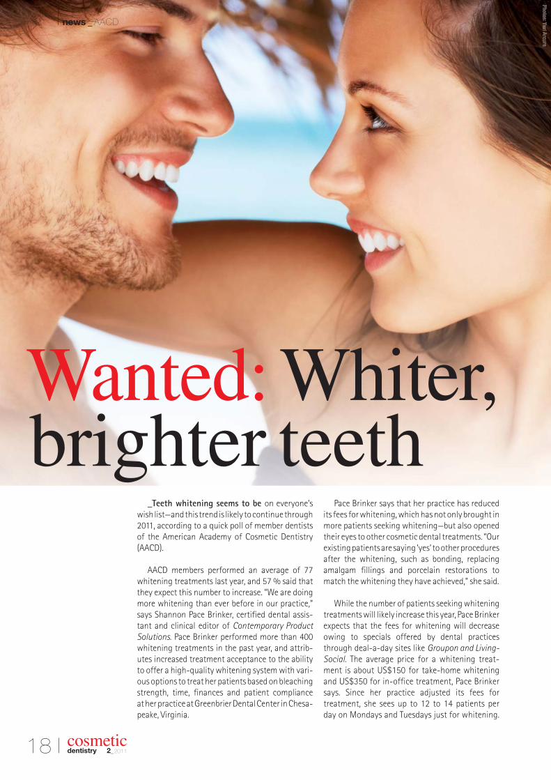
_Teeth whitening seems to be on everyone’swish list—and this trend is likely to continue through2011, according to a quick poll of member dentistsof the American Academy of Cosmetic Dentistry(AACD).
AACD members performed an average of 77whitening treatments last year, and 57 % said thatthey expect this number to increase. “We are doingmore whitening than ever before in our practice,”says Shannon Pace Brinker, certified dental assis-tant and clinical editor of Contemporary ProductSolutions. Pace Brinker performed more than 400whitening treatments in the past year, and attrib-utes increased treatment acceptance to the abilityto offer a high-quality whitening system with vari-ous options to treat her patients based on bleachingstrength, time, finances and patient compliance at her practice at Greenbrier Dental Center in Chesa -peake, Virginia.
Pace Brinker says that her practice has reducedits fees for whitening, which has not only brought inmore patients seeking whitening—but also openedtheir eyes to other cosmetic dental treatments. “Ourexisting patients are saying ‘yes’ to other proceduresafter the whitening, such as bonding, replacingamalgam fillings and porcelain restorations tomatch the whitening they have achieved,” she said.
While the number of patients seeking whiteningtreatments will likely increase this year, Pace Brinkerexpects that the fees for whitening will decreaseowing to specials offered by dental practicesthrough deal-a-day sites like Groupon and Living-Social. The average price for a whitening treat-ment is about US$150 for take-home whitening and US$350 for in-office treatment, Pace Brinker says. Since her practice adjusted its fees for treatment, she sees up to 12 to 14 patients per day on Mondays and Tuesdays just for whitening.
Wanted: Whiter, brighter teeth
I news _ AACD
“Our case acceptance has exceeded our expecta-tions with these adjusted fees,” Pace Brinker said.
AACD members said their practices generatedabout US$19,100 on average from whitening lastyear. The majority of AACD members polled said thatthey provide in-office and take-home whiteningtreatments. In addition, 22 % said that their patientshave told them that they use over-the-counter orcommercially available whitening treatments.
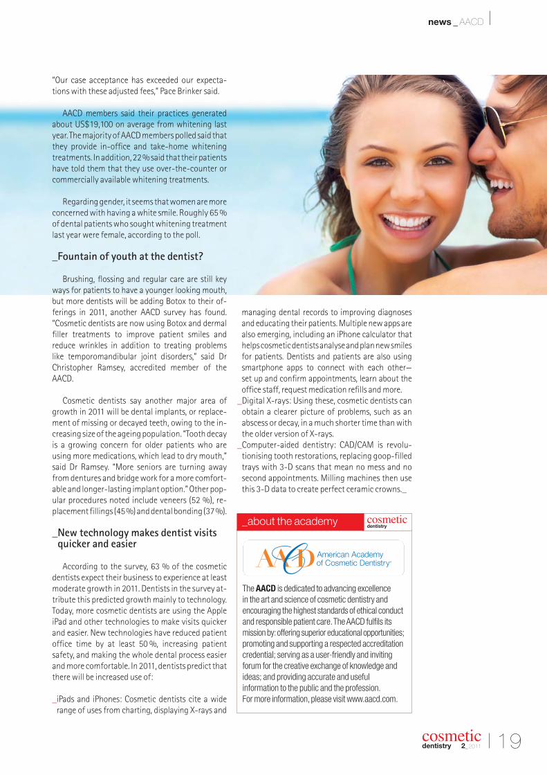
Regarding gender, it seems that women are moreconcerned with having a white smile. Roughly 65 %of dental patients who sought whitening treatmentlast year were female, according to the poll.
_Fountain of youth at the dentist?
Brushing, flossing and regular care are still keyways for patients to have a younger looking mouth,but more dentists will be adding Botox to their of -ferings in 2011, another AACD survey has found.“Cosmetic dentists are now using Botox and dermalfiller treatments to improve patient smiles and reduce wrinkles in addition to treating problems like temporomandibular joint disorders,” said DrChris topher Ramsey, accredited member of theAACD.
Cosmetic dentists say another major area ofgrowth in 2011 will be dental implants, or replace-ment of missing or decayed teeth, owing to the in-creasing size of the ageing population. “Tooth decayis a growing concern for older patients who are using more medications, which lead to dry mouth,”said Dr Ramsey. “More seniors are turning awayfrom dentures and bridge work for a more comfort-able and longer-lasting implant option.” Other pop-ular procedures noted include veneers (52 %), re-placement fillings (45 %) and dental bonding (37 %).
_New technology makes dentist visitsquicker and easier
According to the survey, 63 % of the cosmeticdentists expect their business to experience at leastmoderate growth in 2011. Dentists in the survey at-tribute this predicted growth mainly to technology.Today, more cosmetic dentists are using the AppleiPad and other technologies to make visits quickerand easier. New technologies have reduced patientoffice time by at least 50 %, increasing patientsafety, and making the whole dental process easierand more comfortable. In 2011, dentists predict thatthere will be increased use of:
_iPads and iPhones: Cosmetic dentists cite a widerange of uses from charting, displaying X-rays and
managing dental records to improving diagnosesand educating their patients. Multiple new apps arealso emerging, including an iPhone calculator thathelps cosmetic dentists analyse and plan new smilesfor patients. Dentists and patients are also usingsmartphone apps to connect with each other—set up and confirm appointments, learn about the office staff, request medication refills and more.
_Digital X-rays: Using these, cosmetic dentists canobtain a clearer picture of problems, such as an abscess or decay, in a much shorter time than withthe older version of X-rays.
_Computer-aided dentistry: CAD/CAM is revolu-tionising tooth restorations, replacing goop-filledtrays with 3-D scans that mean no mess and nosecond appointments. Milling machines then usethis 3-D data to create perfect ceramic crowns._
I 19
news _ AACD I
cosmeticdentistry 2_2011
The AACD is dedicated to advancing excellence in the art and science of cosmetic dentistry and encouraging the highest standards of ethical conductand responsible patient care. The AACD fulfils itsmission by: offering superior educational opportunities; promoting and supporting a respected accreditationcredential; serving as a user-friendly and inviting forum for the creative exchange of knowledge andideas; and providing accurate and useful information to the public and the profession.For more information, please visit www.aacd.com.
cosmeticdentistry
_about the academy
20 I
I news _ iPad
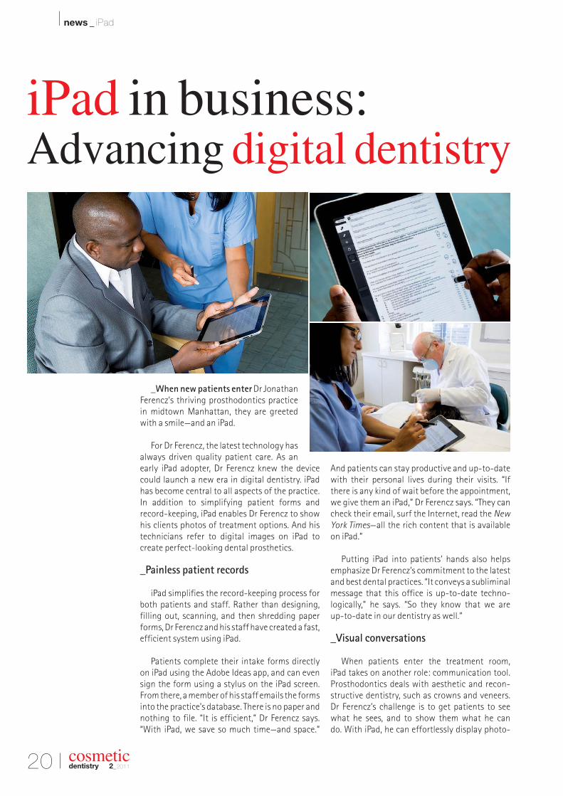
_When new patients enter Dr JonathanFerencz’s thriving prosthodontics practicein midtown Manhattan, they are greetedwith a smile—and an iPad.
For Dr Ferencz, the latest technology hasalways driven quality patient care. As anearly iPad adopter, Dr Ferencz knew the devicecould launch a new era in digital dentistry. iPadhas become central to all aspects of the practice.In addition to simplifying patient forms andrecord-keeping, iPad enables Dr Ferencz to showhis clients photos of treatment options. And histechnicians refer to digital images on iPad to create perfect-looking dental prosthetics.
_Painless patient records
iPad simplifies the record-keeping process forboth patients and staff. Rather than designing,filling out, scanning, and then shredding paperforms, Dr Ferencz and his staff have created a fast,efficient system using iPad.
Patients complete their intake forms directlyon iPad using the Adobe Ideas app, and can evensign the form using a stylus on the iPad screen.From there, a member of his staff emails the formsinto the practice’s database. There is no paper andnothing to file. “It is efficient,” Dr Ferencz says.“With iPad, we save so much time—and space.”
And patients can stay productive and up-to-datewith their personal lives during their visits. “Ifthere is any kind of wait before the appointment,we give them an iPad,” Dr Ferencz says. “They cancheck their email, surf the Internet, read the New
York Times—all the rich content that is availableon iPad.”
Putting iPad into patients’ hands also helpsemphasize Dr Ferencz’s commitment to the latestand best dental practices. “It conveys a subliminalmessage that this office is up-to-date techno -logically,” he says. “So they know that we are up-to-date in our dentistry as well.”
_Visual conversations
When patients enter the treatment room, iPad takes on another role: communication tool.Prosthodontics deals with aesthetic and recon-structive dentistry, such as crowns and veneers.Dr Ferencz’s challenge is to get patients to seewhat he sees, and to show them what he can do. With iPad, he can effortlessly display photo-
cosmeticdentistry 2_2011
iPad in business: Advancing digital dentistry
I 21
news _ iPad I
cosmeticdentistry 2_2011
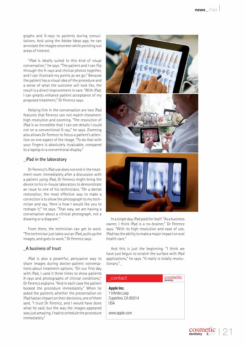
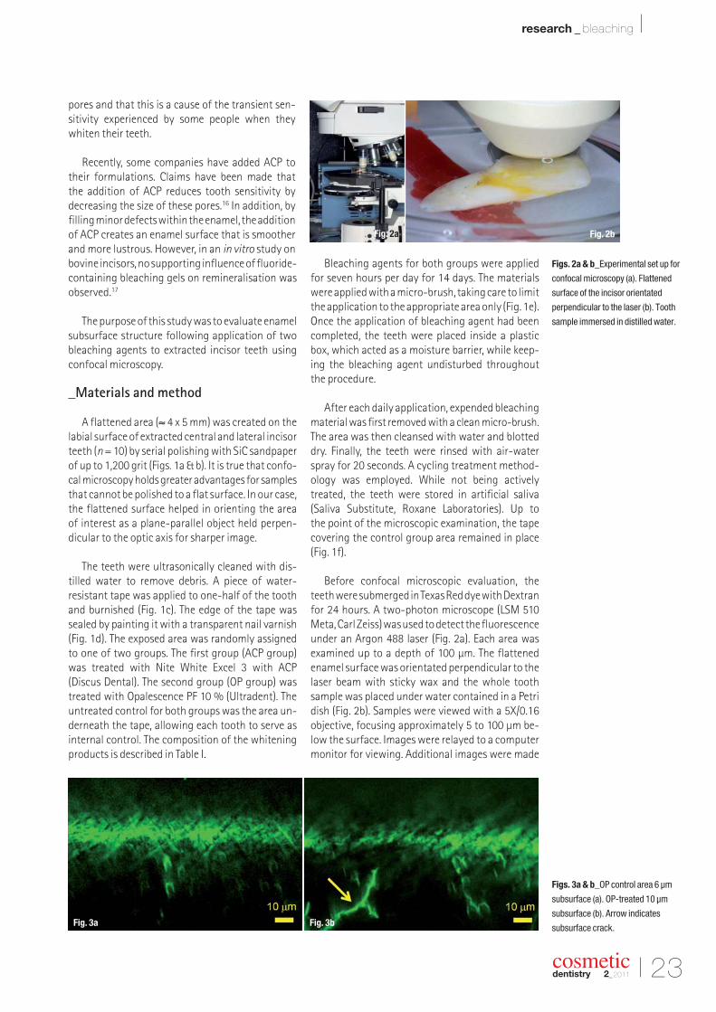
graphs and X-rays to patients during consul -tations. And using the Adobe Ideas app, he can annotate the images onscreen while pointing outareas of interest.
“iPad is ideally suited to this kind of visual conversation,” he says. “The patient and I can flipthrough the X-rays and clinical photos together,and I can illustrate my points as we go.” Becausethe patient has a visual idea of the procedure anda sense of what the outcome will look like, the result is a direct improvement in care. “With iPad,I can greatly enhance patient acceptance of myproposed treatment,” Dr Ferencz says.
Helping him in the conversation are two iPadfeatures that Ferencz can not match elsewhere:high resolution and zooming. “The resolution ofiPad is so incredible that I can see details I couldnot on a conventional X-ray,” he says. Zoomingalso allows Dr Ferencz to focus a patient’s atten-tion on one aspect of the image. “To do that withyour fingers is absolutely invaluable, compared to a laptop or a conventional display.”
_iPad in the laboratory
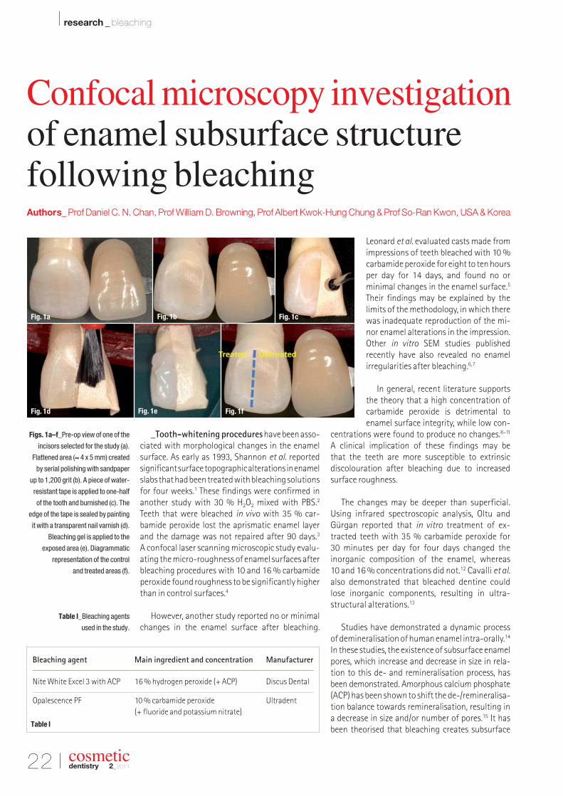
Dr Ferencz’s iPad use does not end in the treat-ment room. Immediately after a discussion with a patient using iPad, Dr Ferencz might bring thedevice to his in-house laboratory to demonstratean issue to one of his technicians. “On a dentalrestoration, the most effective way to make a correction is to show the photograph to my tech-nician and say, ‘Here is how I would like you to reshape it,’” he says. “That way, we are having aconversation about a clinical photograph, not adrawing or a diagram.”
From there, the technician can get to work.“The technician just takes out an iPad, pulls up theimages, and goes to work,” Dr Ferencz says.
_A business of trust
iPad is also a powerful, persuasive way to share images during doctor-patient conversa-tions about treatment options. “On our first daywith iPad, I used it three times to show patients X-rays and photographs of clinical conditions,” Dr Ferencz explains. “And in each case the patientbooked the procedure immediately.” When heasked the patients whether the presentation oniPad had an impact on their decisions, one of themsaid, “I trust Dr Ferencz, and I would have donewhat he said, but the way the images appearedwas just amazing. I had to schedule the procedureimmediately.”
In a single day, iPad paid for itself. “As a businessowner, I think iPad is a no-brainer,” Dr Ferenczsays. “With its high resolution and ease of use,iPad has the ability to make a major impact on oralhealth care.”
And this is just the beginning. “I think we have just begun to scratch the surface with iPadap plications,” he says. “It really is totally revolu -tionary.”_
Apple Inc.
1 Infinite Loop
Cupertino, CA 95014
USA
www.apple.com
cosmeticdentistry
_contact
22 I
I research _ bleaching
_Tooth-whitening procedureshave been asso-ciated with morphological changes in the enamelsurface. As early as 1993, Shannon et al. reportedsignificant surface topographic alterations in enamelslabs that had been treated with bleaching solutionsfor four weeks.1 These findings were confirmed inanother study with 30 % H2O2 mixed with PBS.2
Teeth that were bleached in vivo with 35 % car-bamide peroxide lost the aprismatic enamel layerand the damage was not repaired after 90 days.3
A confocal laser scanning microscopic study evalu-ating the micro-roughness of enamel surfaces afterbleaching procedures with 10 and 16 % carbamideperoxide found roughness to be significantly higherthan in control surfaces.4
However, another study reported no or minimalchanges in the enamel surface after bleaching.
Leonard et al. evaluated casts made fromimpressions of teeth bleached with 10 %carbamide peroxide for eight to ten hoursper day for 14 days, and found no or minimal changes in the enamel surface.5
Their findings may be explained by thelimits of the methodology, in which therewas inadequate reproduction of the mi-nor enamel alterations in the impression.Other in vitro SEM studies published recently have also revealed no enamel irregularities after bleaching.6,7
In general, recent literature supportsthe theory that a high concentration ofcarbamide peroxide is detrimental toenamel surface integrity, while low con-
centrations were found to produce no changes.8–11
A clinical implication of these findings may be that the teeth are more susceptible to extrinsic discolouration after bleaching due to increased surface roughness.
The changes may be deeper than superficial. Using infrared spectroscopic analysis, Oltu andGürgan reported that in vitro treatment of ex-tracted teeth with 35 % carbamide peroxide for 30 minutes per day for four days changed the inorganic composition of the enamel, whereas 10 and 16 % concentrations did not.12 Cavalli et al.
also demonstrated that bleached dentine couldlose inorganic components, resulting in ultra-structural alterations.13
Studies have demonstrated a dynamic process of demineralisation of human enamel intra-orally.14
In these studies, the existence of subsurface enamelpores, which increase and decrease in size in rela-tion to this de- and remineralisation process, hasbeen demonstrated. Amorphous calcium phosphate(ACP) has been shown to shift the de-/remineralisa-tion balance towards remineralisation, resulting ina decrease in size and/or number of pores.15 It hasbeen theorised that bleaching creates subsurface
cosmeticdentistry 2_2011
Figs. 1a–f_Pre-op view of one of the
incisors selected for the study (a).
Flattened area (≈ 4 x 5 mm) created
by serial polishing with sandpaper
up to 1,200 grit (b). A piece of water-
resistant tape is applied to one-half
of the tooth and burnished (c). The
edge of the tape is sealed by painting
it with a transparent nail varnish (d).
Bleaching gel is applied to the
exposed area (e). Diagrammatic
representation of the control
and treated areas (f).
Table I_Bleaching agents
used in the study.
Fig. 1a Fig. 1b Fig. 1c
Fig. 1d Fig. 1e Fig. 1f
Confocal microscopy investigation of enamel subsurface structure following bleachingAuthors_ Prof Daniel C. N. Chan, Prof William D. Browning, Prof Albert Kwok-Hung Chung & Prof So-Ran Kwon, USA & Korea
Bleaching agent Main ingredient and concentration Manufacturer
Nite White Excel 3 with ACP 16 % hydrogen peroxide (+ ACP) Discus Dental
pores and that this is a cause of the transient sen -sitivity experienced by some people when theywhiten their teeth.
Recently, some companies have added ACP totheir formulations. Claims have been made that the addition of ACP reduces tooth sensitivity by decreasing the size of these pores.16 In addition, byfilling minor defects within the enamel, the additionof ACP creates an enamel surface that is smootherand more lustrous. However, in an in vitro study onbovine incisors, no supporting influence of fluoride-containing bleaching gels on remineralisation wasobserved.17
The purpose of this study was to evaluate enamelsubsurface structure following application of twobleaching agents to extracted incisor teeth usingconfocal microscopy.
_Materials and method
A flattened area (≈ 4 x 5 mm) was created on thelabial surface of extracted central and lateral incisorteeth (n = 10) by serial polishing with SiC sandpaperof up to 1,200 grit (Figs. 1a & b). It is true that confo-cal microscopy holds greater advantages for samplesthat cannot be polished to a flat surface. In our case,the flattened surface helped in orienting the area of interest as a plane-parallel object held perpen -dicular to the optic axis for sharper image.
The teeth were ultrasonically cleaned with dis-tilled water to remove debris. A piece of water- resistant tape was applied to one-half of the toothand burnished (Fig. 1c). The edge of the tape wassealed by painting it with a transparent nail varnish(Fig. 1d). The exposed area was randomly assigned to one of two groups. The first group (ACP group)was treated with Nite White Excel 3 with ACP (Discus Dental). The second group (OP group) wastreated with Opalescence PF 10 % (Ultradent). Theuntreated control for both groups was the area un-derneath the tape, allowing each tooth to serve asinternal control. The composition of the whiteningproducts is described in Table I.
Bleaching agents for both groups were appliedfor seven hours per day for 14 days. The materialswere applied with a micro-brush, taking care to limitthe application to the appropriate area only (Fig. 1e).Once the application of bleaching agent had beencompleted, the teeth were placed inside a plasticbox, which acted as a moisture barrier, while keep-ing the bleaching agent undisturbed throughoutthe procedure.
After each daily application, expended bleachingmaterial was first removed with a clean micro-brush.The area was then cleansed with water and blotteddry. Finally, the teeth were rinsed with air-waterspray for 20 seconds. A cycling treatment method-ology was employed. While not being activelytreated, the teeth were stored in artificial saliva(Saliva Substitute, Roxane Laboratories). Up to the point of the microscopic examination, the tapecovering the control group area remained in place(Fig. 1f).
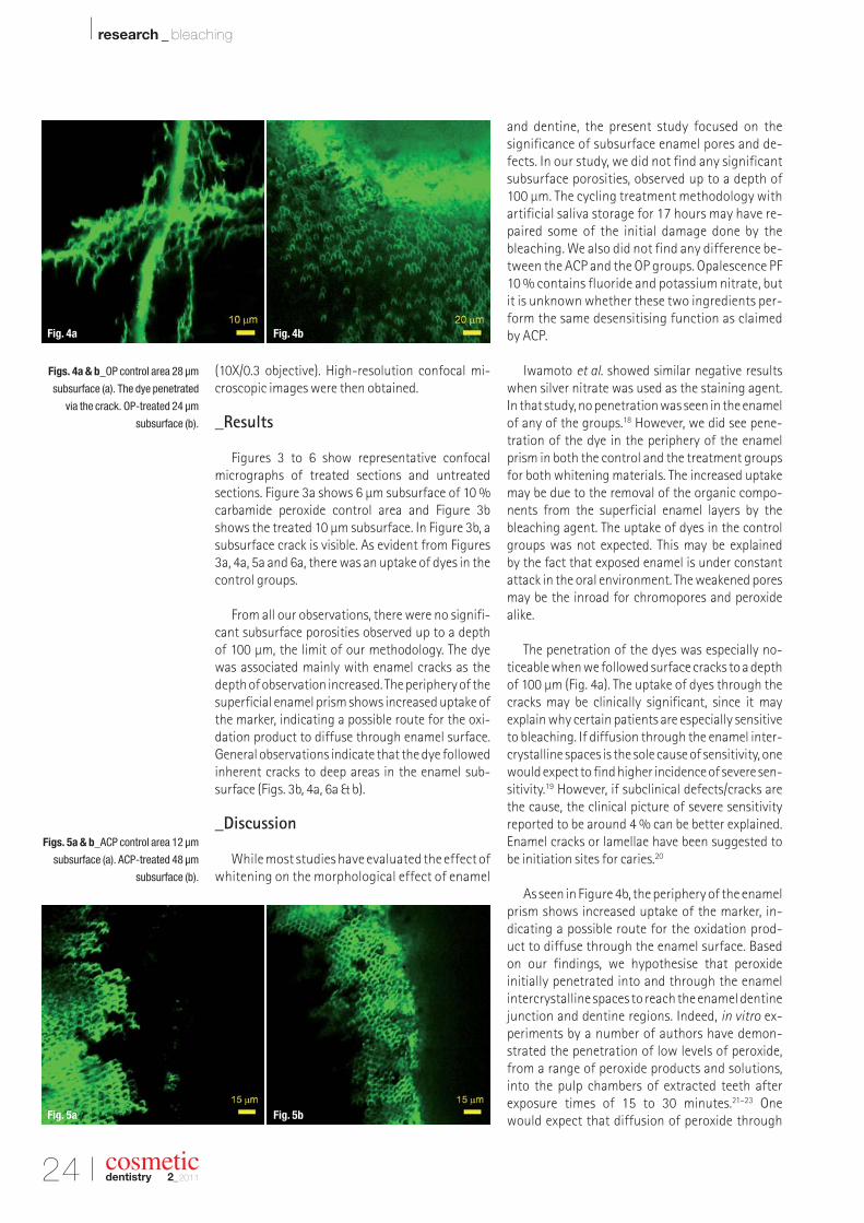
Before confocal microscopic evaluation, theteeth were submerged in Texas Red dye with Dextranfor 24 hours. A two-photon microscope (LSM 510Meta, Carl Zeiss) was used to detect the fluorescenceunder an Argon 488 laser (Fig. 2a). Each area was examined up to a depth of 100 µm. The flattenedenamel surface was orientated perpendicular to thelaser beam with sticky wax and the whole toothsample was placed under water contained in a Petridish (Fig. 2b). Samples were viewed with a 5X/0.16objective, focusing approximately 5 to 100 µm be-low the surface. Images were relayed to a computermonitor for viewing. Additional images were made
Figs. 2a & b_Experimental set up for
confocal microscopy (a). Flattened
surface of the incisor orientated
perpendicular to the laser (b). Tooth
sample immersed in distilled water.
Figs. 3a & b_OP control area 6 µm
subsurface (a). OP-treated 10 µm
subsurface (b). Arrow indicates
subsurface crack.
I 23
research _ bleaching I
cosmeticdentistry 2_2011
Fig. 2bFig. 2a
Fig. 3a Fig. 3b
24 I
I research _ bleaching
cosmeticdentistry 2_2011
(10X/0.3 objective). High-resolution confocal mi-croscopic images were then obtained.
_Results
Figures 3 to 6 show representative confocal micrographs of treated sections and untreated sections. Figure 3a shows 6 µm subsurface of 10 %carbamide peroxide control area and Figure 3bshows the treated 10 µm subsurface. In Figure 3b, asubsurface crack is visible. As evident from Figures3a, 4a, 5a and 6a, there was an uptake of dyes in thecontrol groups.
From all our observations, there were no signifi-cant subsurface porosities observed up to a depth of 100 µm, the limit of our methodology. The dye was associated mainly with enamel cracks as thedepth of observation increased. The periphery of thesuper ficial enamel prism shows increased uptake ofthe marker, indicating a possible route for the oxi-dation product to diffuse through enamel surface.General observations indicate that the dye followedinherent cracks to deep areas in the enamel sub -surface (Figs. 3b, 4a, 6a & b).
_Discussion
While most studies have evaluated the effect ofwhitening on the morphological effect of enamel
and dentine, the present study focused on the significance of subsurface enamel pores and de-fects. In our study, we did not find any significantsubsurface porosities, observed up to a depth of100 µm. The cycling treatment methodology withartificial saliva storage for 17 hours may have re-paired some of the initial damage done by thebleaching. We also did not find any difference be-tween the ACP and the OP groups. Opalescence PF10 % contains fluoride and potassium nitrate, butit is unknown whether these two ingredients per-form the same desensitising function as claimedby ACP.
Iwamoto et al. showed similar negative resultswhen silver nitrate was used as the staining agent.In that study, no penetration was seen in the enamelof any of the groups.18 However, we did see pene-tration of the dye in the periphery of the enamelprism in both the control and the treatment groupsfor both whitening materials. The increased uptakemay be due to the removal of the organic compo-nents from the superficial enamel layers by thebleaching agent. The uptake of dyes in the controlgroups was not expected. This may be explained by the fact that exposed enamel is under constant attack in the oral environment. The weakened poresmay be the inroad for chromopores and peroxidealike.
The penetration of the dyes was especially no-ticeable when we followed surface cracks to a depthof 100 µm (Fig. 4a). The uptake of dyes through thecracks may be clinically significant, since it may explain why certain patients are especially sensitiveto bleaching. If diffusion through the enamel inter-crystalline spaces is the sole cause of sensitivity, onewould expect to find higher incidence of severe sen-sitivity.19 However, if subclinical defects/cracks arethe cause, the clinical picture of severe sensitivityreported to be around 4 % can be better explained.Enamel cracks or lamellae have been suggested tobe initiation sites for caries.20
As seen in Figure 4b, the periphery of the enamelprism shows increased uptake of the marker, in -dicating a possible route for the oxidation prod-uct to diffuse through the enamel surface. Basedon our findings, we hypothesise that peroxide initially penetrated into and through the enamel inter crystalline spaces to reach the enamel dentinejunction and dentine regions. Indeed, in vitro ex-periments by a number of authors have demon-strated the penetration of low levels of peroxide,from a range of peroxide products and solutions,into the pulp chambers of extracted teeth after exposure times of 15 to 30 minutes.21–23 One would expect that diffusion of peroxide through
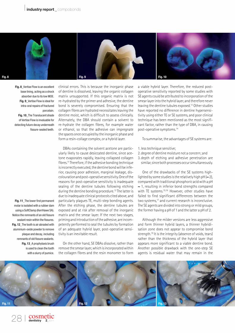
Figs. 4a & b_OP control area 28 µm
subsurface (a). The dye penetrated
via the crack. OP-treated 24 µm
subsurface (b).
Figs. 5a & b_ACP control area 12 µm
subsurface (a). ACP-treated 48 µm
subsurface (b).
Fig. 4a Fig. 4b
Fig. 5a Fig. 5b
I 25
research _ bleaching I
cosmeticdentistry 2_2011
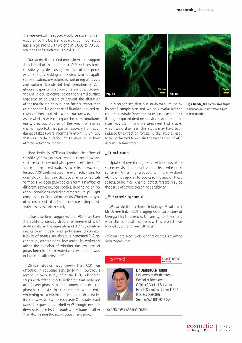
Figs. 6a & b_ACP control area 46 µm
subsurface (a). ACP-treated 46 µm
subsurface (b).
the intercrystalline spaces would be easier for per-oxide, since the Dextran dye we used in our studyhas a high molecular weight of 3,000 to 70,000,while that of a hydroxyl radical is 17.
Our study did not find any evidence to supportthe claim that the addition of ACP reduces toothsensitivity by decreasing the size of the pores. Another study looking at the simultaneous appli -cation of admixture solutions containing citric acidand sodium fluoride did find formation of CaF2
globules deposited on the enamel surface. However,the CaF2 globules deposited on the enamel surfaceappeared to be unable to prevent the alteration of the apatite structure during further exposure toacidic agents. No evidence of fluoride-induced re-covery of the modified apatite structure was found.As for whether ACP can repair the pores simultane-ously, previous studies of the repair of etchedenamel reported that partial recovery from suchdamage takes several months in vivo.24 It is unlikelythat our study du ration of 14 days could have offered noticeable repair.
Hypothetically, ACP could reduce the effect ofsensitivity if the pore sizes were reduced. However,such reduction would also prevent efficient dif -fusion of hydroxyl radicals to effect bleaching. Instead, ACP could act via different mechanisms, forexample by influencing the type of anion or radicalsformed. Hydrogen peroxide can form a number ofdifferent active oxygen species, depending on re -action conditions, including temperature, pH, lightand presence of transition metals. Whether one typeof anion or radical is less prone to causing sensi -tivity deserves further study.
It has also been suggested that ACP may have the ability to directly depolarise nerve endings.25
Additionally, in the generation of ACP by combin-ing calcium nitrate and potassium phosphate, 0.25 % of potassium nitrate is generated.26 A re-cent study on traditional low sensitivity whiteners raised the question of whether the low level ofpotas sium nitrate generated as a by-product was, in fact, clinically relevant.27
Clinical studies have shown that ACP was effective in reducing sensitivity.16,25 However, arecent in vivo study of 9 % H2O2 whitening strips with fifty subjects indicated that daily use of a Casein phosphopeptide-amorphous calciumphosphate paste in conjunction with toothwhitening has a minimal effect on tooth sensitiv-ity compared with a placebo paste. Our study resultraised the question of whether ACP might exert its desensitising effect through a mechanism otherthan decreasing the size of subsurface pores.
It is recognised that our study was limited by its small sample size and we only evaluated theenamel substrate. Severe sensitivity can be initiatedthrough exposed dentine substrate. Another criti-cism may stem from the argument that cracks,which were shown in this study, may have been induced by extraction forces. Further studies needto be performed to explain the mechanism of ACPdesensitisation better.
_Conclusion
Uptake of dye through enamel intercrystallinespaces exists in both control and bleached enamelsurfaces. Whitening products with and without ACP did not appear to decrease the size of thesespaces. Subclinical enamel defects/cracks may bethe cause of severe bleaching sensitivity.
_Acknowledgement
We would like to thank Dr Katsuya Miyake and Mr Darren Baker, Cell Imaging Core Laboratory atGeorgia Health Sciences University, for their helpwith the confocal microscopy. This project wasfunded by a grant from Ultradent._
Editorial note: A complete list of references is available
_Besides the physical and mechanical proper-ties of dental amalgam, one of the main reasons for its success is its clinical simplicity and forgivingtechnique. The derisory “drill and fill” slogan associ-ated with dental treatment pertinently describesthe provision of an amalgam restoration. The usualprotocol for amalgam restorations is a single-stageprocedure. Following decay excavation and toothpreparation, amalgam is placed directly into thecavity and anatomically curved and burnished. Inaddition, amalgam restorations are relatively tech-nique insensitive, have favourable wear resistanceand high strength, are inexpensive and the post- operative expansion of the material helps “seal” cavity margins.
Amalgam’s demise started in the eighties, withquestions being raised about excessive tooth re-moval for creating undercuts for retention, metalcorrosion products, poor aesthetics and possiblemercury toxicity.1 Since then, the profession hassought suitable alternatives for this iconic and
ubiquitous restorative material—the candidate:resin-based composites. The last few decades havewitnessed phenomenal research and improvementof composite technology, allaying concerns regard-ing wear resistance, retention of tooth structure,marginal adaptability and post-operative sensitivity.However, the unflagging Achilles’ heel of compos-ites is polymerisation shrinkage, which compro-mises the longevity of the restoration.2 Never -theless, newer materials have sought to overcomemany of the negative effects associated with poly-merisation shrinkage. The basis for improvementhas been two-fold: firstly, a better understandingand efficacy of dentine bonding; and, secondly, development of the chemical composition of resin-based composites to meet the challenges of poly-merisation shrinkage, including superior physicaland mechanical properties to meet the hostile de-mands of the oral cavity. In order to appreciate therationale for the development of compobonds, it isimportant to chart the scientific breakthroughs ofboth dentine bonding and resin-based composites.
_Historical
The ideal restorative material should be aesthetic,adhesive, abrasion-resistant and bioactive to en-courage regeneration, rather than repair, of the den-tal hard tissues. The last six decades have witnessedthe introduction of many innovative materials asamalgam substitutes, and to fulfil the criteria of anideal restorative dental material. These newer mate-rials can be categorised as resins and glass-ionomerswith numerous hybrids, consisting of combinationsof both materials. Resins yield a superior bond toenamel, but a less predictable bond to dentine.3
Conversely, glass-ionomers bond better to dentine by offering true chemical adhesion and releasing fluoride for bioactivity, but have inferior mechanicalproperties compared with resins. Numerous hybridmaterials such as resin-modified glass-ionomers,compomers and giomers have sought to exploit thebeneficial properties of both materials, with varyingdegrees of success. For example, in 2001 giomerswere introduced, incorporating a pre-reacted glassfiller to facilitate fluoride release from a resin-basedcomposite.4
cosmeticdentistry 2_2011
Compobond: Evolution of anew restorative dental materialAuthor_ Dr Irfan Ahmad, UK
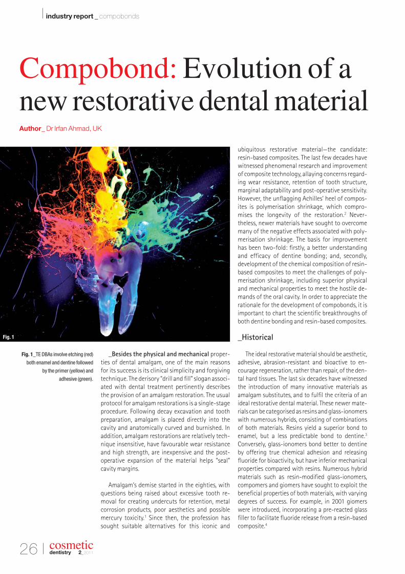
Fig. 1_TE DBAs involve etching (red)
both enamel and dentine followed
by the primer (yellow) and
adhesive (green).
Fig. 1
Other classes of materials include siloranes andormocers. Whilst the silorane-based compositeshave the lowest polymerisation shrinkage of anyresin, they display mixed mechanical properties: flexural strength (FS) and modulus of elasticity (MOE)are higher, but their compressive strength and microhardness are lower compared with methacry-late-based composites.5 Ormocer technology is another addition to the dental restorative armamen-tarium, having excellent wear resistance, but poorpolishability. The evolution of compobonds, launchedin 2009, is based on the premise of the promising clinical outcomes of dentine bonding agent (DBAs)and resin-based composites.
_Dentine bonding agents
The acid-etch technique, introduced by Buono-core in 1955, was seminal and opened the doors tothe possibilities of achieving a bond to natural toothsubstrates with artificial acrylic-based restoratives.6
Whilst bonding to enamel has changed little since its inception more than half a century ago, bondingto dentine has proved far more elusive, under-going enormous changes. A major advancement for achieving a sustainable bond to dentine was the introduction of the total-etch (TE) technique7 inthe late seventies (Fig. 1).
The first self-etching (SE) primer, combining anetchant and primer in a single step, was introduced inthe early nineties.8 The SE primers not only simplifiedbonding to dentine, but also eliminated the clinicalerrors associated with this exacting procedure. The result was a more predicable dentine bond and longevity of a composite resin filling. The next
decade witnessed many formulations, includingetchant+primer followed by adhesive, etchant fol-lowed by primer+adhesive, and more recently in the mid-nineties, combining all three constituents,etchant+primer+adhesive, in a single product and a one-step procedure (Fig. 2).
Contemporary DBAs can be divided into two varieties: TE or SE. To complicate matters further, the TE bonding systems are available as either three-or two-step systems, and SE as either two- or one-step systems, which are available as three-, two- orone-bottle components. Therefore, to resolve someof these dilemmas in choosing a DBA, simplifyingclinical techniques and minimising errors, the currenttrend is moving away from multi-component andmulti-step bonding systems.9 Also, encouragingly,both TE and SE varieties have bond strengths to dentine that are comparable to that of enamel (approximately 22 MPa).10
The salient difference between the TE and SEagents is that an initial etching stage is requiredwith the former, but unnecessary with the latter. For TE, both enamel and dentine are simultaneouslyetched, usually with phosphoric acid, and followedby application of the primer and adhesive, or bothcomponents together in a single liquid. With SEagents, precursory etching is superfluous, since this is concurrently performed with the primer andadhesive.
Although SE agents expedite the bonding proce-dure, the major difference between TE and SE bond-ing agents concerns the smear layer. With TE agents,the etching and drying of dentine is susceptible to
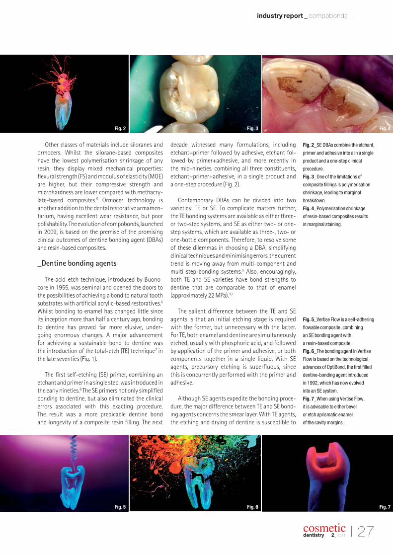
Fig. 2_SE DBAs combine the etchant,
primer and adhesive into a in a single
product and a one-step clinical
procedure.
Fig. 3_One of the limitations of
composite fillings is polymerisation
shrinkage, leading to marginal
breakdown.
Fig. 4_Polymerisation shrinkage
of resin-based composites results
in marginal staining.
Fig. 5_Vertise Flow is a self-adhering
flowable composite, combining
an SE bonding agent with
a resin-based composite.
Fig. 6_The bonding agent in Vertise
Flow is based on the technological
advances of OptiBond, the first filled
dentine-bonding agent introduced
in 1992, which has now evolved
into an SE system.
Fig. 7_When using Vertise Flow,
it is advisable to either bevel
or etch aprismatic enamel
of the cavity margins.
I 27
industry report _ compobonds I
cosmeticdentistry 2_2011
Fig. 3 Fig. 4Fig. 2
Fig. 6 Fig. 7Fig. 5
28 I
I industry report _ compobonds
cosmeticdentistry 2_2011
clinical errors. This is because the inorganic phase of dentine is dissolved, leaving the organic collagen matrix unsupported. If this organic matrix is not re-hydrated by the primer and adhesive, the dentinebond is severely compromised. Ensuring that the collagen fibres are hydrated necessitates leaving thedentine moist, which is difficult to assess clinically.Alternately, the DBA should contain a solvent to re-hydrate the collagen fibres, for example water or ethanol, so that the adhesive can impregnate the spaces once occupied by the inorganic phase andform a resin-collage complex, or a hybrid layer.
DBAs containing the solvent acetone are partic -ularly likely to cause desiccated dentine, since ace-tone evaporates rapidly, leaving collapsed collagenfibres.11 Therefore, if the adhesive bonding techniqueis incorrectly executed, the dentine bond will be infe-rior, causing poor adhesion, marginal leakage, dis-colouration and post-operative sensitivity. One of thereasons for post-operative sensitivity is inadequatesealing of the dentine tubules following etching during the dentine bonding procedure.12 The latter isdue to inadequate clinical protocols cited above, andparticularly plagues TE, multi-step bonding agents.After the etching phase, the dentine tubules are exposed and at risk after removal of the inorganicmatrix and the smear layer. If the next two stages,priming and introduction of the adhesive, are incom-petently performed to seal the tubules by formationof an adequate hybrid layer, post-operative sensi -tivity is an inevitable result.
On the other hand, SE DBAs dissolve, rather thanremove the smear layer, which is incorporated withinthe collagen fibres and the resin monomer to form
a viable hybrid layer. Therefore, the reduced post- operative sensitivity reported by some studies withSE agents could be attributed to incorporation of thesmear layer into the hybrid layer, and therefore neverleaving the dentine tubules exposed.13 Other studieshave reported no difference in dentine hypersensi-tivity using either TE or SE systems, and poor clinicaltechnique has been mentioned as the most signifi-cant factor, rather than the type of DBA, in causingpost-operative symptoms.14
To summarise, the advantages of SE systems are:
1. less technique sensitive;2. degree of dentine moisture not a concern; and3. depth of etching and adhesive penetration are
similar, since both processes occur simultaneously.
One of the drawbacks of the SE systems high-lighted by some studies is the relatively high pH (≈ 2),compared with traditional phosphoric acid with a pH≈ 1, resulting in inferior bond strengths comparedwith TE systems.15,16 However, other studies havefailed to find significant differences between the two systems,17 and current research is inconclusive.The SE agents are divided into strong or mild groups,the former having a pH of 1 and the latter a pH of 2.
Although the milder versions are less aggressiveand form thinner hybrid layers, a thinner hybridi -sation zone does not appear to compromise bondstrength.18 It is the integrity (absence of voids, tears)rather than the thickness of the hybrid layer that appears more significant to a viable dentine bond.Another possible drawback with the one-step SEagents is residual water that may remain in the
Fig. 8_Vertise Flow is an excellent
base lining, acting as a shock
absorber due to its low MOE.
Fig. 9_Vertise Flow is ideal for
intra-oral repairs of fractured
porcelain.
Fig. 10_The Translucent shade
of Vertise Flow is invaluable for
detecting future decay underneath
fissure-sealed teeth.
Fig. 11_The lower first permanent
molar is isolated with a rubber dam
using a SoftClamp (KerrHawe SA).
Notice the remnants of an old fissure
sealant resin within the fissures.
Fig. 12_The tooth is air abraded with
aluminium-oxide powder to remove
plaque and decay, including
remnants of old fissure sealants.
Fig. 13_A prophylaxis brush
is used to clean the tooth
with a slurry of pumice.
Fig. 9 Fig. 10Fig. 8
Fig. 12 Fig. 13Fig. 11
I 29
industry report _ compobonds I
cosmeticdentistry 2_2011
Fig. 14_The pumice removes
residues of the aluminium-oxide
power.
Fig. 15_The rinsed tooth following
cleaning with pumice.
Figs. 16a & b_Etchant is dispensed
into the fissures (a) and continued
to the surrounding uncut,
aprismatic enamel (b).
Fig. 17_The classical frosty
appearance of etched enamel is
clearly evident (compare with Fig. 12).
Fig. 18a_Vertise Flow is dispensed
into the fissures.
dentine tubules, thereby leading to incomplete poly-merisation of the adhesive, and ultimately compro-mising retention.19However, SE agents are innovativeproducts in their infancy, and further in vivo mediumand long-term trials are necessary to investigatethese concerns.
The eighth and future generations of DBAsshould improve on the seventh generation of SEbonding agents by incorporating substances for re-generating natural hard tissues, rather than limitingtheir functions to adhesion. These new so-calledbiomaterials should have anti-bacterial, bioactiveand biofunctional properties, amongst other prop-erties.
_Resin-based composites
The number of resin-based composites on themarket is both impressive and overwhelming. Devel-opments in composite technology over the last fewdecades has resulted in many novel products, and selecting the correct material for a specific clinicalscenario is both daunting and perplexing. The follow-ing generic classification categorises contemporaryresin-based composites, together with their prop -erties and uses:
_1. Hybrids: Universal or general purpose; low wearresistance, long-term increase in surface rough-ness, for example posterior restorations, Class I and II.
_2. Micro-filled: More aesthetic than hybrids, retainssurface polish/lustre over time, for example Class III,IV and V; highly filled (loaded) variants for extremeocclusal loads, for example Class I and II.
_3. Nano-filled: Similar to micro-filled, most aes-thetic; aesthetically demanding regions of themouth, high polishability, excellent optical proper-ties (opalescence, fluorescence), for example ClassIII, IV and direct composite laminate veneers.
_4. Micro- and nano-hybrid varieties: Universal orgeneral purpose.
_5. Flowables: Low viscosity, low MOE, low filler content. Suited for areas of low occlusal loads dueto poor wear resistance, low strength and increasedpolymerisation shrinkage. However, polymerisa-tion stress is also lower owing to the reduced fillercontent. Ideal for small pits and fissures not ex-posed to occlusal loads, primary dentition restora-tions, blocking undercuts for indirect prostheses(for example, inlays and crowns) and stress-reliev-ing liners for deep Class I, II, V and large cavities,preferably fluoride-releasing varieties, for examplegiomer.
Ideally, composites should possess similar physi-cal, mechanical and optical properties to the naturalhard tissues they are replacing. Therefore, for highlyaesthetic restorations, where appearance and opticalissues are of paramount concern, the ideal choice is a micro- or nano-filled composite. However, the later are unsuitable for high-stress-bearing posteriorrestorations owing to poor wear, and in these cir-cumstances a prudent choice is a universal compos-ite, for example a hybrid or micro- or nano-hybrid.
Whilst resin-based composites have revolu-tionised restorative dentistry, they are not withouttheir problems. The main reason for the failure of composite fillings is marginal breakdown and secondary caries.20 However, it is not a fait accompli
Fig. 15 Fig. 16aFig. 14
Fig. 17 Fig. 18aFig. 16b
30 I
I industry report _ compobonds
cosmeticdentistry 2_2011
Fig. 18b_Vertise Flow is dispensed
onto the entire occlusal surface.
Figs. 19a & b_A brush is used to
press Vertise Flow onto the enamel
surface for 15–20 seconds (a)
and to obtain a layer of
< 0.5 mm thickness (b).
Fig. 20_The set Vertise Flow after
appropriate light curing.
Fig. 21_Articulation paper is used
to verify occlusal contacts. Notice
extraneous flash material at the distal
aspect of the permanent molar.
Fig. 22_For mandibular teeth, all
occlusal contacts are removed,
except those on the buccal supporting
cusps. Notice that the distal flash
material has been removed.
that secondary carious lesions will ensue in the pres-ence of an open or discoloured cavo-surface margin.The current thinking is that patient risk factors, suchas oral hygiene, dietary considerations and attitudetowards dental treatment, are pivotal in determiningwhether decay will occur.21
As previously stated, marginal breakdown is at-tributed to polymerisation shrinkage of a compositeduring its setting stage, ranging from 2 to 5 % by vol-ume,22 causing stresses that lead to bonding failureand gap formation (Figs. 3 & 4). Polymerisationstresses can be mitigated by the clinical technique,MOE of the material and cavity configuration or the“C” factor. In an effort to circumvent polymerisationshrinkage, manufacturers have altered the chemicalcomposition of composites to have favourable prop-erties. These include varying the size, shape and volume of the inorganic filler particles, as well as improving adhesion of the fillers to the organic resinmatrix. Other factors that reduce stresses are themethod of setting reaction, for example using pulsecuring,23 and incremental build-up of the compositefilling during placement.24 Another technique (dis-cussed below) is using flowable composites with alower MOE as the initial base-lining layer to absorbpolymerisation stresses and counteract forces at the restoration-dentine interface.25
_Flowable composites
Flowables, introduced nearly two decades ago,have become ubiquitous for many applications. Theyexhibit greater fluidity and elasticity, offering betteradaptation to internal cavity walls and are very userfriendly. In addition, the radiopacity of these resins
allows effortless detection of secondary caries, andreveals marginal integrity or open margins. A restora-tive material should possess radiopacity that isslightly greater than enamel to distinguish decay,26
and greater than the ISO minimum standard or equalto or greater than an equivalent thickness of alu-minium. This is especially significant if flowables are used as intra-coronal initial lining layers belowsubsequent increments of universal composite. The ISO standard for minimum FS of outer occlusalrestorative materials is 80 MPa, which is displayed bymost of the current flowables on the market. The FSdepends on the specific proprietary material, rangingfrom 70 to approximately 100 MPa, deterioratingover time, and is approximately 80 % compared withnon-flowable analogues.
Although micro-leakage is a multifactorial phe-nomenon, MOE of the material is a crucial factor that determines its magnitude. Similar to FS, MOE is variable, depending on the product, ranging from 3 to over 11 GPa, and also decreasing over time. Theviscoelastic properties of a flowable determine itsflowability and clinical handling. The flow character-istics of flowable composites can be divided into low,medium and high flow.27 Each variety is suitable fordifferent clinical tasks. For example, a highly flowablematerial is desirable as a liner or fissure sealant, to adhere to cavity walls or fissures crevices intricately,while a less flowable variety is preferable for smallcavities or repairs, where excessive slumping is a nui-sance. Currently, most of the flowable compositespossess little bacterial inhibitory po tential, especiallyagainst S. mutans, the main in fective agent of den-tal caries. Whilst a few flowables on the market claim anti-bacterial activity, the effect is usually
Fig. 19a Fig. 19bFig. 18b
Fig. 21 Fig. 22Fig. 20
I 31
industry report _ compobonds I
cosmeticdentistry 2_2011
ephemeral, effective for only a few days.28 Futurecomposite developments should endeavour to in -corporate both anti-bacterial and bioactivity in theirformulations for enhanced therapeutic value.
In conclusion, flowables are useful for areas of reduced occlusal stresses, but are contra-indicated for bulk build-ups in stress-bearing areas. Their popu-larity is due to ease of use and flexible adaptability, especially in areas of limited access. The clinical applica-tions include fissure sealing, small cavities, base liners,repairing voids in defective restorations and blockingundercuts for subsequent indirect prostheses.
_Evolution of a new resin-based restorative: Compobond
As discussed above, the state-of-the-art of den-tine bonding systems are the SE agents that obviatethe need to perform an initial etching phase, whileyielding bond strengths that are comparable tobonding to enamel. Also, the pinnacle of resin-basedcomposite technology is the introduction of nanoand nano-hybrid composites. The advancements inboth bonding agents and resins have now evolved byuniting these two materials to produce a new dentalrestorative: compobond.
Compobonds exploit the benefits of SE DBAs andnano-filled resins, eliminating the precursory bond-ing stage necessary to adhere a resin to tooth sub-strate, and are termed self-adhering composites. Inessence, an era is emerging in which composites, sim-ilar to amalgam fillings, can be placed in a single step,eliminating errors, expediting protocols, and improv-ing predictability and longevity of restorations.
The first compobond, called Vertise Flow (Kerr),was introduced in 2009, a self-adhering flowablecombining a resin-based composite and an SE bonding agent based on the seventh-generationDBA OptiBond All-in-One (Kerr). Vertise Flow is alight-cured composite with similar properties toconventional flowables but with the added ad -vantage of eliminating the bonding stage that isprerequisite before using any resin-based restora-tive (Fig. 5).
Characteristics and properties of Vertise Flow
Vertise Flow incorporates the properties of theDBA OptiBond, the first filled bonding agent intro-duced in 1992 (Fig. 6), that realised the potential ofusing a filled adhesive as a shock absorber beneathresin-based composite restorations. The bondingmechanism of OptiBond to dentine is two-fold:firstly, chemical adhesion is realised by the phos-phate function group of the GPDM monomer (glycerol phosphate dimetharcrylate) uniting withthe calcium ions within the tooth; and, secondly, micromechanical adhesion by formation of the hy-brid layer composed of resin impregnation with thecollagen fibres and the dentine smear layer. InitialSEM and TEM images from the University of Leuven,Belgium, show tight adaptation of Vertise Flow toboth dentine and enamel. In addition, micro-leak-age tests show that Vertise Flow’s marginal integrityis comparable to conventional (i.e. non-adhering)flowable composite when used in combination withan SE bonding agent.29
The shear bond strength (SBS) achievable withVertise Flow and dentine is approximately 25 MPa,
Fig. 23_The post-op view showing
sealed fissures and the high lustre
obtained after polishing
with Opti1Step Polisher
(compare with Fig. 11).
Fig. 24_Pre-op view showing
cavitation in the occlusal surfaces
of a maxillary molar and pre-molar.
The molar also requires replacement
of an occlusal defective composite
filling.
Fig. 25_Cavity preparation using
micro-diamond burs for minimising
excessive tooth removal.
Fig. 26_All aprismatic enamel
margins are carefully bevelled.
Figs. 27a & b_The initial layer
of Vertise Flow should be < 0.5mm
thickness (a) and spread with a brush
to ensure intimate contact with the
cavity walls and bevelled margins (b).
Fig. 24 Fig. 25Fig. 23
Fig. 27a Fig. 27bFig. 26
32 I
I industry report _ compobonds
comparable to bonding to cut, prismatic enamel.However, the SBS is lower with uncut or aprismaticenamel, which is similar to using SE agents alone.For this reason, it is advisable to either bevel or etchaprismatic enamel beforehand to ensure a sustain-able and durable marginal seal (Fig. 7). Conversely,pre-etching dentine when using Vertise Flow re-duces the SBS to dentine, and is therefore contra-indicated. Another disadvantage of pre-etchingdentine is opening dentine tubules that may not besealed to the same depth by the subsequent use ofVertise Flow, and could contribute to post-operativesensitivity.
The chemical composition of Vertise Flow incor-porates four types of fillers, with a total 70 % load-ing. The inclusion of nano-ytterbium fluoride yieldsexcellent radiopacity and fluoride release (for bio -activity), the pre-polymerised fillers reduce micro-leakage, and nanoparticles improve polishabilityand thixotropic properties. The FS is 120 MPa formitigating bulk fracture, and the MOE is low, ap-proximately 7 GPa, for shock absorbing capability(Fig. 8).
Because Vertise Flow functions as both a dentineadhesive and a resin restorative material, a longercuring time is necessary to ensure that both constituents are fully polymerised. In addition, thelight-curing reaction also halts the etching processof the SE agent, increasing its pH from approxi-mately 2 to 7, so that continual acidity does noterode the dentine bond.
A further advantage of Vertise Flow is inclusion of the acidic phosphate monomer, which provides
chemical adhesion to a variety of intaglio surfaces ofindirect prostheses, including non-precious alloys,gold, alumina, zirconia and silica ceramics, for exam-ple feldspathic, lithium-disilicate or other pressed ceramic systems. This adhesive property is excep-tionally useful for repairing intra-oral fracturedporcelain, for example all-ceramic crowns, inlays oronlays, or patching up chipped porcelain defectswithout replacing the entire prosthesis (Fig. 9).
The handling properties of Vertise Flow are fav -ourable for numerous applications. For example, its viscosity occupies a middle ground, neither tooviscous nor too runny, and therefore satisfies a widerrange of clinical applications, both as a liner/sealantand for entire small cavity restorations. Vertise Flowis available in a selection of shades for the subtlest of aesthetic requirements, ranging from XL forbleached teeth to Translucent for fissure sealing thatallows visibility of any future decay (Fig. 10).
Similar to glass-ionomers and their variations,compobonds offer adhesion to natural tooth sub-strate. However, whilst both materials have similarindications, their properties and handling charac-teristics vary considerably. Glass-ionomers essential -ly adhere exclusively to dentine, have low mechan-ical strength, average aesthetics and low wear, butoffer both fluoride release and recharge. In addition,the setting reaction is affected by the degree ofmoisture of dentine, and involves a two-stage clin-ical procedure. On the other hand, compobonds offer dentine and enamel bonding, high mechanicalstrength, low wear, better aesthetics, a single-stageclinical procedure and fluoride release, but not fluoride recharge.
Fig. 28_The initial layer of
Vertise Flow is light cured before
adding further material.
Fig. 29_The finished restorations are
polished with tips for a high lustre,
ensuring impeccable integration with
the surrounding enamel.
Fig. 30_Pre-op occlusal contacts
to verify that the cavity is not
in a stress-bearing area.
Fig. 31_After rubber dam isolation,
pumice is used to cleanse the tooth.
Fig. 32_A cavity is prepared with
bevelled enamel margins.
Fig. 33_Post-op view showing the
cavity restored with A3 Vertise Flow.
cosmeticdentistry 2_2011
Fig. 29 Fig. 30Fig. 28
Fig. 32 Fig. 33Fig. 31
I 33
industry report _ compobonds I
cosmeticdentistry 2_2011
_Clinical applications of Vertise Flow
The clinical uses of Vertise Flow are not unlikethose of conventional flowables, but with the addedadvantage of eliminating the bonding stage. Beloware some suggested applications.
Fissure sealing
One of the fundamental treatments for preventa-tive dentistry is fissure sealing of posterior permanentteeth soon after their eruption into the oral cavity. Tra-ditionally, this has been achieved solely with enameletching, relying on micromechanical retention, anddepending on diet, the fissure sealants require peri-odic replacement or repair. Using Vertise Flow insteadof conventional fissure sealants offers not only mi-cromechanical retention, but also chemical adhesionto the enamel via the SE agent that links with the calcium ions from the hydroxyapatite matrix.
The following case reports on fissure sealing of afirst permanent molar tooth in a 14-year-old child.Ideally, the tooth should be isolated with a rubberdam to ensure moisture control and a clear operatingfield (Fig. 11). Initially, the tooth was air abraded withaluminium-oxide powder to clean the pits and fis-sures, remove the plaque biofilm, superficial incipientdecay and, if present, remnants of old fissure sealants(Fig. 12). The cleansing was continued with a slurry of pumice to eliminate residues of the aluminiumpowder (Figs. 13 & 14). After rinsing off the pumice(Fig. 15), 37 % phosphoric acid was dispensed to etch the pits and fissures (Fig. 16a) and surrounding uncut, aprismatic enamel (Fig. 16b). The classic frostyetched enamel appearance was clearly visible after
rinsing off the etchant and drying the occlusal sur-face (Fig. 17).
Since Vertise Flow should be refrigerated to ensure extended shelf life and optimal performance,it is advisable to remove it beforehand to so that thematerial reaches room temperature. The Translucentshade of Vertise Flow was dispensed generously (Figs. 18a & b) and brushed onto the enamel to ensureintimate contact with its surface, and spread to a thinlayer of less than 0.5 mm (Figs. 19a & b). The coatedsurface(s) were light cured for 20 seconds with a curing light with an output of 800 MW/cm2 (Fig. 20).The rubber dam was then removed and articulationpaper placed to check occlusal contacts (Fig. 21). Allthe articulation paper marks, except those on thesupporting buccal cusps (palatal cusps for maxillaryteeth), were adjusted and polished with Opti1StepPolisher (KerrHawe SA; Figs. 22 & 23).
Small cavities in areas of minimum occlusal stressare ideal candidates for minimally invasive, micro-dentistry. Incipient carious lesions either can be mon-itored if the patient risk factors are low or may requireintervention for patients with a propensity for dentaldecay. In this case, a 13-year-old female patient, whois an occasional attendee and relatively indifferent to dental treatment, was treated.
The preoperative status shows the maxillary second pre-molar and first molar with occlusal cav -itations, and an old defective composite occlusalrestoration in the molar (Fig. 24). Cavity preparationwas carried out using small diamond burs specifically
Fig. 34_Pre-op view showing
defective amalgam fillings in two
mandibular molars. Pre-op occlusal
contacts are identified before placing
the rubber dam.
Fig. 35_The old amalgam
restorations are removed.
Fig. 36_After removing soft decayed
dentine, the enamel margins are
finished with a 90° cavo-surface
angle and etched with phosphoric
acid for 15 seconds.
Fig. 37_The etched enamel
peripheries are clearly visible
on the second mandibular molar.
Fig. 38_The etched enamel
peripheries are clearly visible
on the third mandibular molar.
Fig. 39_Vertise Flow is dispensed
into the cavity.
Fig. 35 Fig. 36Fig. 34
Fig. 38 Fig. 39Fig. 37
34 I
I industry report _ compobonds
designed to minimise removal of tooth substrate (Fig. 25). Current research shows that it is unnecessaryto remove all decayed dentine. Instead, the cavity mar-gins are clearly defined for creating a hermetic seal forguarding against the negative effects of the dentalbiofilm, which perpetually colonises the tooth sur-face.30 As previously mentioned, in order to improvebond strength to aprismatic enamel, the margins canbe either etched or bevelled (Fig. 26). The initial layer ofVertise Flow should be less than 0.5 mm in thicknessand pressed into the recesses of the cavity floor andwalls (Figs. 27a & b). The initial layer of Vertise Flow wasfirst light cured (Fig. 28) before completing the cavitywith additional layers. Finally, the restoration was pol-ished with Opti1Step Polisher and an OptiShine brush(KerrHawe SA) to yield a high lustre gloss (Fig. 29).
Class V and small buccal cavities
Class V cavities have variable presentations. Theexposed dentine in Class V cavities can be the result of enamel loss due to erosion, abrasion abfraction or infectious caries. The dentine reaction is highly er-ratic, often leading to formation of hyper-mineralised sclerotic dentine that is resistant and less receptive to dentine adhesion.31 Therefore, in the presence of sclerotic dentine, all DBAs are less efficacious andpresent a challenge for dentine bonding. For this rea-son, Vertise Flow is unsuitable for Class V lesions withblatant dentine hyper-mineralised sclerotic dentine.
If sclerotic dentine is absent, adhesion with DBAsis superior (28 MPa) compared with compomers (15 MPa) or a glass-ionomer (2.5 MPa).32 For smallbuccal cavities within enamel, Vertise Flow is the idealmaterial of choice, as shown in the following case.
Preoperative articulation paper marks verifiedthat the buccal lesion was free of occlusal, stress-bearing contacts (Fig. 30). After isolation with a rub-ber dam, the tooth was cleaned with a slurry ofpumice (Fig. 31) and a cavity was prepared with bev-elled enamel margins (Fig. 32). The final result showsrestoration of the cavity with A3 Vertise Flow afterpolishing with Opti1Step Polisher (Fig. 33).
Stress-relieving linings
The rationale for using different composites forvarious increments of a restoration is that the mate-rials should possess similar properties to the naturaldentine and enamel they are replacing. Dentine has a lower MOE and is therefore better able to absorbstresses than enamel. For this reason, in circum-stances in which the cavity extends into dentine, theinitial layer of composite should have shock-absorb-ing capabilities that are similar to dentine.
The polymerisation contraction stresses of aresin-based composite are directly related to its fillervolume, which also affects its mechanical properties,such as wear resistance and MOE. High filler contentresults in less contraction, which in turn influencesthe marginal integrity of the restoration.33 Flowableshave approximately 25 % less filler than their non-flowable counterparts and therefore undergo in-creased volumetric shrinkage. However, since flow-ables have about 50 % less MOE than non-flowables,they can absorb more stresses and, in theory, main-tain superior marginal integrity.34
The MOE of flowables ranges from as low as 1.4 GPa(low filler volume) to as high as 12.5 GPa (high filler
Figs. 40a & b_A brush is used to
spread the Vertise Flow on the cavity
walls (a) and floor, ensuing that
it is evenly spread with a thickness
less than 0.5 mm (b).
Fig. 41_The initial Vertise Flow lining
is light cured.
Fig. 42_A regular composite,
Herculite XRV Ultra, is used in
increments for replacing dentine
and building up individual buccal
and lingual cusps.
Fig. 43_An endodontic file, loaded
with brown Kolor + Plus stain, is
dragged through the unset composite
resin to create fissure patterns in the
second molar restoration.
Fig. 44_An endodontic file, loaded
with brown Kolor + Plus stain,
is dragged through the unset
composite resin to create fissure
patterns in the third molar restoration.
cosmeticdentistry 2_2011
Fig. 40b Fig. 41Fig. 40a
Fig. 43 Fig. 44Fig. 42
I 35
industry report _ compobonds I
cosmeticdentistry 2_2011
content).35 In addition to filler content, other con-stituents such as the type and quantity of resin, photoinitiators and accelerators also influence the final MOE of the material. As a generalisation, flow-ables with a lower MOE may act as shock absorberswhen placed as pre-cured liners below subsequentincrements of non-flowables. But current studies areinconclusive regarding this beneficial property,36, 37
and further research is necessary to clarify the issue.
In the following case, large Class I cavities in twomandibular molars were restored using Vertise Flowas an initial layer to act as a shock absorber beforecompleting the restoration with subsequent layers of a non-flowable composite. This case shows thesecond and third mandibular molars with defectiveamalgam restorations requiring replacement. In ad-dition, these teeth also exhibit bruxism activity withtooth wear, resulting in occlusal enamel loss. Initialocclusal contacts were verified (Fig. 34) before plac-ing a rubber dam and removing the amalgam restora-tions. Notice the extensive decay in the third molar(Fig. 35). Since molars are prone to high occlusalforces, placing bevels on enamel margins is unsuit-able because the thin layer of composite resin pe-riphery is likely to fracture during mastication. How-ever, to achieve an efficacious bond to aprismaticenamel, it is prudent to etch the periphery whilemaintaining a 90° cavo-surface angle (Fig. 36).
After thoroughly rinsing and drying, the etchedenamel periphery of both cavities was clearly visible(Figs. 37 & 38). Vertise Flow was dispensed into the cavity, brushed to ensure that the material wasevenly spread along the cavity walls and floor, mak-ing sure that its thickness did not exceed 0.5 mm
(Figs. 39–40b). This initial layer of Vertise Flow waslight cured for 20 seconds and acted as the stress- relieving lining (Fig. 41). Subsequent layers of the filling were built-up using increments of a regularcomposite, Herculite XRV Ultra (Kerr), to replace den-tine, and then successively building-up the buccaland lingual cusps38 separately without contacting the opposing sides (Fig. 42).
Staining fissures is a contentious issue; some patients are indifferent to this practice, while othersadamantly refuse to have their teeth stained. Forthose patients who are unconcerned, fissure stainingand patterns impart a realistic appearance to a com-posite filling. The technique involves using differentstains, for example Kolor + Plus (Kerr), that aredragged through the unset composite resin using anendodontic reamer or file (Figs. 43 & 44). Once the de-sired fissure pattern had been created, the compositewas light cured (Figs. 45 & 46). After removing therubber dam, articulation paper was used to check oc-clusal contacts (Fig. 47), and nec essary adjustmentswere made to ensure occlusal harmony. The finalstage was achieving a high surface lustre and textureusing Opti1Step Polisher. The post-operative viewshows composite fillings emulating natural cuspsand fissure patterns, with impercep tible transitionbetween the composite filing and surroundingenamel (Fig. 48).
Blocking undercuts
Another useful application of flowables is block-ing undesirable undercuts prior to providing indirectrestorations. Undercuts often complicate many clin-ical and laboratory procedures, for example impres-
Fig. 45_Once the fissure pattern has
been established, the composite
is light cured in the second molar.
Fig. 46_Once the fissure pattern has
been established, the composite
is light cured in the third molar.
Fig. 47_After removing the rubber
dam, occlusal contacts are checked
using articulation paper.
Fig. 48_The filling is polished to
a high lustre with Opti1Step Polisher,
ensuring an indiscernible transition
between the composite filling
and surrounding natural tooth.
Fig. 49_Underlying decay is evident
after removing an old amalgam filling
from the maxillary molar.
Fig. 50_Undercuts are evident
following excavation of soft,
carious dentine.
Fig. 46 Fig. 47Fig. 45
Fig. 49 Fig. 50Fig. 48
36 I
I industry report _ compobonds
sion making or restoration fabrication. Unwantedsharp line angles or deficiencies, such as voids, canreadily be blocked and sealed with the easily adapt-able flowable composites for both intra- and extra-coronal tooth preparations.
In the following case, a large amalgam restorationwith underlying profound decay was scheduled foran indirect ceramic inlay. After isolation with a rubberdam, the amalgam filling from the maxillary molar wasremoved, revealing gross carious dentine (Fig. 49). All soft, carious dentine was exacted, leaving blatantundercuts (Fig. 50). Due diligence was exercised notto remove all the hard, deeper decayed dentine toavoid possible pulpal exposure. In this instance, Vertise Flow has a dual function: firstly, to block un-dercuts; and, secondly, to act as a stress-absorbingliner for the subsequent indirect ceramic inlay (Fig. 51).
Repair
Lastly, Vertise Flow can be used for minor repairs,for either chairside or laboratory-made, acrylic basedtemporary restorations such as crowns with air blows or chips or fractures after a period of use in themouth. Once again, the repair protocol is simplifiedand predictable, involving a single step, with theadded benefit of the SE bonding agent within VertiseFlow.
Another form of repair involves the increasinglyproblematic fractures associated with ceramic pros-theses, such as crowns or inlays. Since these types ofall-ceramic indirect restorations are increasinglypopular, the number of fractures is also becomingprogressively more common, and replacement is
costly. Traditionally, ceramic fracture repair involvedseveral stages, that is etching with hydrofluoric acid,silanation and repairing with conventional resin-based composites, either a flowable or non-flowablevariety.
As previously mentioned, Vertise Flow incorpo-rates an acidic phosphate monomer, which linkschemically to many ceramic substrates, such as silica,alumina and zirconia. Therefore, after rougheningthe fracture “lesion” with a diamond bur, only a singlestep is necessary with Vertise Flow, which combinesboth chemical bonding and a repairing composite to“heal” the fracture.
The following case illustrates repair of a fractured,alumina core crown, veneered with silica (felds-pathic) porcelain. The patient presented with a distalfracture of the all-ceramic crown on the maxillary left central incisor (Fig. 52). A shade analysis was performed with the Vita Classic shade guide (VITA).Vertise Flow A2 was chosen for the body of the crown,and the Translucent shade for the incisal edgetranslucency (Fig. 53). Initial cleansing was carriedout with a slurry of pumice to remove the plaquebiofilm (Fig. 54).
To increase the surface area for bonding, the frac-tured porcelain requires pre-treatment roughening,which can be achieved either mechanically or chem -ically. The choice is mainly empirical, de pending on the clinician’s personal experience and penchant foreither technique. Mechanical roughening involves using a rotary instrument followed by cleansing thesite with phosphoric acid (Fig. 55), which does not etchporcelain, but removes any remaining debris (Fig. 56).
Fig. 51_Vertise Flow is used to block
the undercuts and acts as
a stress-relieving lining.
Fig. 52_Pre-op view showing a distal
fracture of the all-ceramic crown on
the maxillary left central incisor.
Fig. 53_Shade analysis to ascertain
colour of existing crown.
Vertise Flow A2 and Translucent
shades were selected to repair
the fractured porcelain.
Fig. 54_Pumice is used to cleanse
the crown and remove any
plaque biofilm.
Fig. 55_The porcelain surface is
mechanically roughened with
a diamond bur and then cleansed
with phosphoric acid.
Fig. 56_Prepared porcelain site.
cosmeticdentistry 2_2011
Fig. 52 Fig. 53Fig. 51
Fig. 55 Fig. 56Fig. 54
I 37
industry report _ compobonds I
cosmeticdentistry 2_2011
The chemical method involves etching the porcelainwith hydrofluoric acid for three minutes. It is impor-tant to note that only silica-based ceramics can beetched with hydro fluoric acid, and if the fracture extends deeper into an alumina or zirconia substruc-ture, the latter will require mechanical rougheningwith a diamond bur.
Customarily, the next stage is application of hy-drofluoric acid and silane for creating a silica–silanebond. However, this is superfluous when using Vertise Flow, as the later incorporates an acidic phosphate monomer that bonds to silica, as well as alumina and zirconia ceramics. The A2 shade of Vertise Flow was dispensed directly onto the etchedfracture site (Fig. 57), and spread intimately, ensuringfirm contact with the porcelain (Fig. 58). In order to mimic the incisal edge translucency, the Trans -lucent shade of Vertise Flow was used at the incisaledge (Fig. 59), and slightly overbuilt to compensatefor the polishing stage (Fig. 60). Finishing and polishing were carried out using sequentially finergrit discs (OptiDisc, Kerr; Fig. 61), creating a sur-face roughness (Ra) of approximately 0.2 µm, equalto or less than the threshold required for bacterial andplaque adhesion (Ra = 0.2 µm).39 The post-operativeresult shows the polished repair harmoniously blend-ing with the surrounding porcelain (Fig. 62).
Similar to porcelain repairs, existing chipped ormarginally stained composites (both direct and in direct restorations) can be effortlessly repaired. The protocol is minimally invasive, economical, quick and spares the patient protracted appointments to replace the entire restoration, which can instead be monitored at periodic recalls.
_Conclusion
This article has introduced the evolution of a newdental restorative material, the compobonds. The dis-cussion has focused on the rationale for the develop-ment of compobonds, citing technological advancesin both DBAs and resin-based composite formula-tions. In addition, a proprietary product, Vertise Flowis described as the first generation of flowable com-pobonds with clinical applications similar to existingflowable composites, and some novel uses, such asdirect, intra-oral, porcelain fracture repairs. The ben-efits of combining an SE DBA with a composite-resineliminate the technique-sensitive protocols associ-ated with dentine bonding, making the entire processsimpler and more predictable. However, as with anynew material, scientific scrutiny and clinical trials willuntimely judge the efficacy of compobonds and, ifsuccessful, will pave the way for non-flowable vari-eties to simplify direct composite restorations._
Editorial note: A complete list of references is available from the publisher.
_The dental laboratory industry has searchedfor a material that is structurally sound and highly aesthetic. This material is now available inlithium-disilicate glass ceramic (IPS e.max Press,Ivoclar Vivadent), which is a material like no other in dentistry. The IPS e.max Press lithium disilicate isthe first structural (long-lasting) material that isaesthetic, even without layering, when its HighTranslucency ingots are used.
Its high strength comes from the lithium-disili-cate crystals. The IPS e.max lithium disilicate iscomposed of quartz, lithium dioxide, phosphoricoxide, alumina, potassium oxide and other com -ponents. Overall, this composition yields a glass ceramic that shows low thermal expansion when it is processed.
Polyvalent ions dissolved in the glass provide the desired colour of the lithium-disilicate material.These colour-releasing ions are homogeneouslydistributed in the single-phase material, resulting inthe elimination of colour pigment imperfections inthe microstructure.
With its four levels of opacity and translucency—High Opacity, Medium Opacity, Low Translucencyand High Translucency—IPS e.max Press enableslaboratory ceramists to satisfy different aestheticdemands and deliver a beautiful and strong restora-tion. Overall, these materials demonstrate specificadvantages, such as higher edge strength versustraditional glass-ceramic materials (can be finishedmore thinly without chipping); the low viscosity ofthe heated ingot, which enables pressing to verythin dimension (enabling minimal preparation orno-preparation veneers); and a chameleon effectowing to higher translucency. In some cases, mini-mal tooth preparation is needed (for example, thinveneers) and IPS e.max lithium disilicate enablesrestorations to be pressed as thin as 0.3 mm, whilestill ensuring strength of 400 MPa.
This article guides readers through the processof accurately maintaining the incisal edge posi-tion, length, shape and contour of provisionalrestorations when fabricating final IPS e.max Pressanterior restorations. Additionally, if one were to
cosmeticdentistry 2_2011
Figs. 1 & 2_Pre-op 1:2 view showing
discoloured temporary repairs
to the central incisors.
Fig. 3_An approved model of the
provisional restorations was perfected
by adding wax and reducing stone.
Fig. 4_The facial incisal area was
bevelled back 0.5 mm using
a contour stone.
One step closer to nature: Imitatingnatural optical properties usinglithium-disilicate restorationsAuthor_ Dr Bradley L. Jones, USA
Fig. 2
Fig. 1
Fig. 4Fig. 3
take the enamel (0.5 mm) off a natural tooth, the internal dentine effects would be visible. The tech-nique described here also provides a step-by-stepguide to precisely mimicking these internal ef-fects. By enamelling over these effects quickly and ac curately, the restoration can be returned tofull contour, while including natural optical ef-fects and segmenting both high- and low-valueenamels.
_Case presentation
A 19-year-old male patient wished to improvethe overall appearance of his smile (Figs. 1 & 2). As a child, he had chipped both central incisors andneeded several temporary repairs that were per-formed by a dentist over the years.
The patient underwent a thorough examination.To ensure proper shade matching and design of therestorations, a complete laboratory aesthetic pre-scription, detailed shade mapping, alteration of the type of light source used to take the shade, theamount and colour of the incisal translucency, andsurface texture were obtained and recorded.
An approved model of the provisional restora-tions was perfected by adding wax and reducingstone (Fig. 3). With a pair of dividers, the exactlengths were verified using a model of the provi-sional restorations.
After the facial incisal edge had been out-lined using a red pencil, a 0.3 mm lead pencil line was placed0.5 mm lingually. A contour stone (Komet 9001,
Fig. 5_An undercut was made inside
the silhouette of the incisal half
to ensure the establishment
of a halo effect.
Fig. 6_After smoothing out the
incisal facial area, grey, vanilla and
salmon stains were applied to create
internal effects, then fired.
Fig. 7_IPS e.max OE4 was placed
to shape the internal lobe structures.
They were feathered out after
being formed.
Fig. 8_To reproduce a natural halo
effect, IPS e.max MM Light
was added.
Fig. 9_IPS e.max OE3 was applied
in thin segments to the line angles
and strategic places.
Fig. 10_The IPS e.max TI1 was built
in flush with the previously fired OE3
height of contour and high-value
segments to full contour.
I 39
industry report _ IPS e.max Press I
cosmeticdentistry 2_2011
Fig. 8Fig. 7
Fig. 10Fig. 9
Fig. 6Fig. 5
40 I
I industry report _ IPS e.max Press
cosmeticdentistry 2_2011
Komet) was used to bevel the facial incisal edge back 0.5 mm (Fig. 4). The value was drawn in and a centred diamond disc (Komet K6974) was used to carefully cut in the value area, making certain that a halo effect was established (Fig. 5).
Using a contour stone (Komet 9001), the incisalfacial area was smoothed out to create a canvas forthe internal effects. To create the internal effects,grey, vanilla and salmon IPS e.max Essence stainswere applied and fired (Fig. 6).
IPS e.max Opal Effect 4 (OE4) was placed to shapethe internal lobe structures softly. Once the internallobes had been formed, they were feathered out (Fig. 7). IPS e.max Mamelon (MM) Light was addedto reproduce a natural halo effect (Fig. 8). After a thorough and careful evaluation, the external effects were fired.
A red pencil was used to identify the line angles,as well as places for a segment of high-value pow-der. IPS e.max Opal Effect 3 (OE3) was applied to theline angles in thin segments, as well as to strategicplaces, to achieve a natural optical effect and re- establish the heights of the contour (Fig. 9).
The segments of IPS e.max OE3 were built to 0.5 mm, which was the exact thickness of the initialfacial cut-back, making it faster and easier to returnto the original full contour. IPS e.max OE3 was fired
to ensure that the high-value segments mimickedthe enamel optics found in the natural teeth, afterwhich the IPS e.max Transpa Incisal 1 (TI1) was builtflush with the previously fired OE3 height of the con-tour and high-value segments to full contour (Fig. 10).
The restorations were bisque baked. Then, afterusing a diamond bur (Komet 842R) to smooth thefacial surface, a coarse rubber wheel (Komet 9472C)was used to re-establish the deflective zones and redefine the line angles (Fig. 11). The facial lobeswere recreated with a diamond bur (Komet 842R)after the desired amount of perikymata had beenadded with a diamond bur (Komet 850 016). Therestorations were then glazed and polished.
_Conclusion
Today’s patients have become increasingly moreInternet savvy, demanding higher aesthetics andlonger-lasting restorations. In my opinion, IPS e.maxPress offers the ceramist—for the first time in thehistory of this industry—a restorative material thatis both beautiful and incredibly strong. It surpassesour patients’ expectations, as demonstrated in thecase illustrated here (Figs. 12–14).
_Acknowledgement
I would like to acknowledge Dr James Gorczycafrom Boise, Idaho, for his exceptional excellence indentistry._
_SDI’s Pola AdvancedTooth Whitening Systemis now ten years old!Since its launch in Europeat IDS Cologne in 2001,Pola has white ned mil-lions of smiles around theworld. SDI’s formula forsuccess: a focus on min-imising sensitivity andmaximising whiteningeffectiveness for patientsand dentists alike.
The Pola System is offered for both in-officeand take-home applications. Pola Office+ is anauto-mixing, extremely fast in-office bleachthat whitens teeth in less than half an hour. Theease of use and unique delivery system allowdentists to complete the procedure in a mini-mum amount of time.
Pola Day and Pola Night are take-home tooth-whitening systems used by patients in cus-tom-made tooth-whitening trays. Pola Day ishydrogen-peroxide based, while Pola Night isbased on carbamide peroxide. Both systems are available in three concentrations to allow
a tailor-made whiten-ing programme for allpatients. In ad dition,SDI offers Pola Paint,
a paint-on tooth-whitening system de-signed to be used as
touch-up procedure tomaintain a previouslywhitened smile.
The well-establishedline of Pola tooth-
whiten ing products issoon to be comple -
ment ed by Pola DayCP, which is a 35 %carbamide-peroxide
version of Pola Day. It isa take-home whitener,offering an extremely
fast, 15-minute whitening time, and is perfectfor people who want to bleach their teeth in the comfort of their home._
_With 115,000 visitors and nearly 2,000 ex-hibitors, this year’s International Dental Show (IDS)was the biggest dental trade show ever. The showboasted a 9 % increase compared with 2009. Peoplefrom 148 countries travelled to Cologne to see newproducts, learn about innovative treatment me-thods and network with other dental professionals.Exhibitors from 85 countries seized the opportunityto establish and further contacts, win new customersand open up new markets.
“The world’s leading dental trade fair IDS closed,having achieved outstanding results,” the organisers
summed up after five busy days. Organisers and exhibitors were especially pleased with the largenumber of visitors from abroad. “The most customerswe’ve had so far are from abroad,” Marian Tempel, responsible for marketing at Korean company Neo-biotech, told cosmetic dentistry on the third day ofthe exhibition. IDS visitors came mainly from LatinAmerica and South America, Australia, the US andCanada, but also from Italy, France, the Netherlands,Spain, the UK, Switzerland, Russia, Ukraine, Turkey, Israel, China and India. The exhibition halls were constantly busy and booths extremely well visited.According to the exhibitors, 66 % of which came from
outside Germany, representatives of everything re-lated to dentistry—dental practices and laboratories,trade, the higher education sector—visited theirbooths. The trade show meant a huge financial successfor many exhibitors. Many companies took numerousorders, both domestically and internationally.
“We have succeeded in making IDS even more attractive, both domestically and internationally. The strong increase in international participants especially shows that IDS is the world’s leading den-tal trade show,” Dr Martin Rickert, Chairperson of theAssociation of German Dental Manufacturers, said.“Participants were able to forge high-quality busi-ness contacts between industry and trade profes-sionals as well as between the industry, dentists anddental technicians. Thus, the trade fair once againsignalled better times ahead and generated momen-tum that will help the dental sector stay on course fora successful business year.”
Koelnmesse Executive Vice-President Oliver P.Kuhrt added: “IDS more than satisfied everyone’s expectations. Once again, IDS offered a whole rangeof new products and excellent opportunities to exchange information, communicate with partnersand place orders. That’s why exhibitors, visitors andmedia representatives were all delighted with thetrade fair.”
A visitor survey carried out during IDS found thatnot only exhibitors, but also trade visitors consideredthe exhibition a success. According to the organisers,95 % of the respondents indicated that they were satisfied/very satisfied with the event. They werepleased with the range of products and had achievedtheir goals at the trade fair. Furthermore, 93 % wouldrecommend a visit to IDS to a close business associate.“It’s my first time at the IDS and this is the biggest den-tal trade fair I have ever been to. I have scheduled threedays to see everything,” Dr Dusan Dimitrijevic toldcosmetic dentistry. This dentist from Serbia broughthis son and second-year dental student Lazar with himto Cologne.
_Focus on digital innovation
This year, the focus of interest was on the inno vativenew products and technologies on display. Accordingto Dr Rickert, the trade fair demonstrated that digitalprocesses and technologies are becoming increasinglypopular, since they facilitate even more efficient andhigher quality treatments. In particular, products andsystems that offer users and patients improvements inpreventative care, diagnostics and dental treatmentwere in high demand. Those include ultrasound sys-tems with expanded capabilities that enable painlessand professional preventative care, digital intra-oral
scanners, improved root-canaltreatment methods, new dentalfilling materials, aesthetic dentalcrowns and bridges that lookmost natural, as well as improveddigital X-ray diagnostics that are especially useful in the field ofimplantology.
“As far as we are concerned,the trade fair was very successful,”said Jost C. Fischer, Chairpersonand CEO of Sirona Dental Systems,leader in CAD/CAM technology.“The number of visitors was amaz-ing. In fact, all of our employeeswere in dialogue around the clock.You could clearly see that theeconomy has picked up again. As a result, the atmosphere at thefair was extremely positive. In myopinion, it was the best IDS ever.”
Jürgen Schwichtenberg, President of the Associa-tion of German Dental Technicians’ Guilds (VDZI), anIDS partner, was also very pleased with the trade fair.“From the point of view of the dental technician trade,the IDS 2011 once again proved the dental sector’s innovative power. Considering the variety of productson display in Cologne and the rapid development ofnew, particularly digital technologies, it will be evenmore important in the future for dental technicians to actively supplement these new technologies and so -lutions with their expert knowledge and to put theseinto practice in their laboratories in order to ensure anall-round high-quality treatment. Our partners in thedental industry in general and dentists in particular willbe able to continue to rely on these important services.”
46 I
I meetings _ IDS 2011
One partnership that was started at IDS is becom-ing an important political aspect of the profession:collaboration between the VDZI and the EuropeanAssociation for Dental Technology. The aim of the collaboration is to combine dental technology ex-pertise and provide further training of the higheststandard in both theory and practice so that practi-tioners can learn about the latest state-of-the-artdental technology.
_Speakers’ Corner well visited
Many IDS visitors took advantage of the Spea-kers’ Corner feature to gather information on the latest developments in science and research. Around 80 exhibitors presented their new products and tech-nologies. The presentation topics included implantsystems, digitisation, dental aesthetics, laser tech-nology, dental anaesthesia and the benefits of mod-ern stress management for dentists.
Dr Peter Engel, President of the German Dental Association (GFDI), one of the IDS organisers, is happywith the positive outcome of the trade fair: “Evenmore visitors and exhibitors than in previous yearscan mean only one thing: The profession is progres-sive and medium-sized German businesses are fos-tering innovation—and they’re attracting enormousinterest internationally.”
At the exhibition, the GFDI held a coordinatingconference for aid organisations, at which over 40 participants presented aid projects seeking to improve the dental health of the world’s poor. Theprojects were developed by dentists and dental students who work in impoverished regions all overthe world. Some of them also work in Germany. Theyprovide dental services to a range of disadvantagedpatients, including orphans, homeless people, dis-abled patients, drug addicts and inhabitants of re-mote areas, who would not receive treatment other-wise. To do this work, dentists and students oftenhave to overcome enormous challenges. The coor -dinating conference offered participants a specialopportunity to share their experiences in organisingaid efforts.
In collaboration with the VDZI, the GFDI will alsoorganise the 35th IDS, which will take place from 12 to 16 March 2013._
cosmeticdentistry 2_2011
Unbenannt-4 1 25.01.2011 10:51:07 Uhr
2011
IACA 201128–30 July 2011
San Diego, CA, USA
www.theiaca.com
AAED Annual Meeting2–5 August 2011
San Juan, Puerto Rico
www.estheticacademy.org
FDI Annual World Dental Congress14–17 September 2011
Mexico City, Mexico
www.fdiworldental.org
SCAD Annual Conference23 & 24 September 2011
Chicago, IL, USA
www.scadent.org
Dental-Facial CosmeticInternational Conference27 & 28 October 2011
Dubai, UAE
www.cappmea.com
IFED World Congress2–5 November 2011
Rio de Janeiro, Brazil
www.ifed.org
AIOP International Congress18 & 19 November 2011
Bologna, Italy
www.aiop.com
Greater New York Dental Meeting25–30 November 2011
New York, NY, USA
www.gnydm.org
2012
AACD Scientific Session 20122–5 May 2012
Washington, DC, USA
www.aacd.com
EAED Spring Meeting24–26 May 2012
Antalya, Turkey
www.eaed.org
FDI Annual World Dental Congress29 August–1 September 2012
Hong Kong, China
www.fdiworldental.org
48 I
I meetings _ events
cosmeticdentistry 2_2011
International Events
I 49
about the publisher _ submission guidelines I
cosmeticdentistry 2_2011
submission guidelines:Please note that all the textual components of your submissionmust be combined into one MS Word document. Please do not submit multiple files for each of these items:
_the complete article;_all the image (tables, charts, photographs, etc.) captions;_the complete list of sources consulted; and_the author or contact information (biographical sketch, mailingaddress, e-mail address, etc.).
In addition, images must not be embedded into the MS Word document. All images must be submitted separately, and detailsabout such submission follow below under image requirements.
Text length
Article lengths can vary greatly—from 1,500 to 5,500 words— depending on the subject matter. Our approach is that if you need more or less words to do the topic justice, then please makethe article as long or as short as necessary.
We can run an unusually long article in multiple parts, but thisusually entails a topic for which each part can stand alone be-cause it contains so much information.
In short, we do not want to limit you in terms of article length, so please use the word count above as a general guideline and ifyou have specific questions, please do not hesitate to contact us.
Text formatting
We also ask that you forego any special formatting beyond theuse of italics and boldface. If you would like to emphasise certainwords within the text, please only use italics (do not use underli-ning or a larger font size). Boldface is reserved for article headers.Please do not use underlining.
Please use single spacing and make sure that the text is left jus -tified. Please do not centre text on the page. Do not indent para-graphs, rather place a blank line between paragraphs. Please donot add tab stops.
Should you require a special layout, please let the word processingprogramme you are using help you do this formatting automati-cally. Similarly, should you need to make a list, or add footnotes or endnotes, please let the word processing programme do it foryou automatically. There are menus in every programme that willenable you to do so. The fact is that no matter how carefully done,errors can creep in when you try to number footnotes yourself.
Any formatting contrary to stated above will require us to removesuch formatting before layout, which is very time-consuming.Please consider this when formatting your document.
Image requirements
Please number images consecutively throughout the article by using a new number for each image. If it is imperative that certain images are grouped together, then use lowercase lettersto designate these in a group (for example, 2a, 2b, 2c).
Please place image references in your article wherever they are appropriate, whether in the middle or at the end of a sentence.If you do not directly refer to the image, place the reference at the end of the sentence to which it relates enclosed withinbrackets and before the period.
In addition, please note:
_We require images in TIF or JPEG format._These images must be no smaller than 6 x 6 cm in size at 300 DPI._These image files must be no smaller than 80 KB in size (or theywill print the size of a postage stamp!).
Larger image files are always better, and those approximately the size of 1 MB are best. Thus, do not size large image files downto meet our requirements but send us the largest files available.(The larger the starting image is in terms of bytes, the more lee-way the designer has for resizing the image in order to fill up morespace should there be room available.)
Also, please remember that images must not be embedded intothe body of the article submitted. Images must be submitted separately to the textual submission.
You may submit images via e-mail, via our FTP server or post a CD containing your images directly to us (please contact us for the mailing address, as this will depend upon the country fromwhich you will be mailing).
Please also send us a head shot of yourself that is in accordancewith the requirements stated above so that it can be printed withyour article.
Abstracts
An abstract of your article is not required.
Author or contact information
The author’s contact information and a head shot of the authorare included at the end of every article. Please note the exact information you would like to appear in this section and for-mat it according to the requirements stated above. A short biographical sketch may precede the contact information if you provide us with the necessary information (60 words or less).
Copyright Regulations _cosmetic dentistry_beauty & science is published by Oemus Media AG and will appear in 2011 with one issue every quarter. The magazine
and all articles and illustrations therein are protected by copyright. Any utilisation without the prior consent of editor and publisher is inadmissible and liableto prosecution. This applies in particular to duplicate copies, translations, microfilms, and storage and processing in electronic systems.
Reproductions, including extracts, may only be made with the permission of the publisher. Given no statement to the contrary, any submissions to theeditorial department are understood to be in agreement with a full or partial publishing of said submission. The editorial department reserves the right tocheck all submitted articles for formal errors and factual authority, and to make amendments if necessary. No responsibility shall be taken for unsolicitedbooks and manuscripts. Articles bearing symbols other than that of the editorial department, or which are distinguished by the name of the author, representthe opinion of the afore-mentioned, and do not have to comply with the views of Oemus Media AG.Responsibility for such articles shall be borne by the author.Responsibility for advertisements and other specially labeled items shall not be borne by the editorial department. Likewise, no responsibility shall be assumedfor information published about associations, companies and commercial markets. All cases of consequential liability arising from inaccurate or faulty representation are excluded. General terms and conditions apply, legal venue is Leipzig, Germany.
Published byOemus Media AGHolbeinstraße 2904229 Leipzig, GermanyTel.: +49-341/4 84 74-0Fax: +49-341/4 84 74-2 [email protected]
Printed byMessedruck Leipzig GmbHAn der Hebemärchte 604316 Leipzig, Germany
Advisory BoardDr Michael Miller, USADr Seok-Hoon Ko, Korea
Editorial BoardDr Anthony Au, AustraliaDr Bao Baicheng, ChinaDr Helena Lee, SingaporeDr Hisashi Hisamitsu, JapanDr Jiraporn Charudilaka, ThailandDr Mostaque H. Sattar, BangladeshDr Ratnadeep Patil, IndiaDr Sim Tang Eng, MalaysiaDr Suhit Raj Adhikari, NepalDr Takashi Nakamura, JapanDr Vijayaratnam Vijayakumaran, Sri Lanka
Claudia Salwiczek, Managing Editor
cosmeticdentistry _ beauty & science
is the official publication of:
cosmeticdentistry _ beauty & science
I would like to subscribe to cosmetic dentistry for € 44 inclu-ding shipping and VAT for German customers, € 46 including ship-ping and VAT for customers outside Germany, unless a written can-cellation is sent within 14 days of the receipt of the trial subscrip-tion. The subscription will be renewed automatically every year untila written cancellation is sent to OEMUS MEDIA AG, Holbeinstr. 29,04229 Leipzig, Germany, six weeks prior to the renewal date.
Notice of revocation: I am able to revoke the subscription within 14 days after my order by sending a writtencancellation to OEMUS MEDIA AG, Holbeinstr. 29, 04229 Leipzig, Germany.