COST-EFFECTIVE BRIDGE SAFETY INSPECTIONS
USING UNMANNED AERIAL VEHICLES (UAVS)
FINAL PROJECT REPORT
by
Daniel T. Gillins
Christopher Parrish
Matthew N. Gillins
Oregon State University
Sponsorship
PacTrans
School of Civil and Construction Engineering Oregon State University
for
Pacific Northwest Transportation Consortium (PacTrans)
USDOT University Transportation Center for Federal Region 10
University of Washington
More Hall 112, Box 352700
Seattle, WA 98195-2700
In cooperation with US Department of Transportation-Research and Innovative Technology
Administration (RITA)
Disclaimer
The contents of this report reflect the views of the authors, who are responsible for the
facts and the accuracy of the information presented herein. This document is
disseminated under the sponsorship of the U.S. Department of Transportation’s
University Transportation Centers Program, in the interest of information exchange. The
Pacific Northwest Transportation Consortium, the U.S. Government and matching
sponsor assume no liability for the contents or use thereof.
Technical Report Documentation Page
1. Report No. 2. Government Accession No. 3. Recipient’s Catalog No.
4. Title and Subtitle 5. Report Date
COST-EFFECTIVE BRIDGE SAFETY INSPECTIONS USING UNMANNED October 15, 2016
AERIAL VEHICLES (UAVS)
6. Performing Organization Code
7. Author(s) 8. Performing Organization Report No.
Daniel T. Gillins, Christopher E. Parrish, and Matthew N. Gillins
9. Performing Organization Name and Address 10. Work Unit No. (TRAIS)
PacTrans
Pacific Northwest Transportation Consortium
11. Contract or Grant No.
University Transportation Center for Region 10
DTRT12-G-UTC10 University of Washington More Hall 112 Seattle, WA 98195-2700
12. Sponsoring Organization Name and Address 13. Type of Report and Period Covered
United States of America Research 1/15/2015 – 6/30/2016
Department of Transportation
14. Sponsoring Agency Code
Research and Innovative Technology Administration
15. Supplementary Notes Report uploaded at www.pacTrans.org 16. Abstract
This report presents the results of a study on the use of unmanned aircraft systems (UAS) in bridge inspections. A detailed literature
review was conducted to assess and document the current state of knowledge on the use of UAS in structural inspections and related
engineering applications. A particular focus was on related work done by various state DOTs. Given the technical specifications and
findings documented in the literature review, an item-by -item review of bridge inspection manuals was then performed to assess which
elements of a bridge inspection could potentially benefit from use of UAS. Additionally, various categories of UAS and payloads were
evaluated for bridge inspection. A small multicopter UAS was acquired and used to collect ultra-high-definition video and still imagery
of a large bridge in Independence, Oregon. The imagery was reviewed by project team members and ODOT bridge inspectors. The
results of the Independence Bridge inspection are presented, along with recommendations for further work. The study identified several
challenges on the use of UAS for bridge inspection, including the need to capture very high resolution imagery, and problems due to
strong wind and poor lighting conditions.
17. Key Words Bridge Inspection; Unmanned Aircraft Systems; UAS; Drones 18. Distribution Statement
No restrictions.
19. Security Classification (of this 20. Security Classification (of this 21. No. of Pages 22. Price
report) page)
Unclassified. Unclassified. NA
Form DOT F 1700.7 (8-72) Reproduction of completed page authorized
iii
Table of Contents
Acknowledgments .......................................................................................................................... x
Executive Summary ...................................................................................................................... xi
CHAPTER 1 INTRODUCTION....................................................................................................... 1
CHAPTER 2 LITERATURE REVIEW ......................................................................................... 3
2.1 Unmanned Aircraft Systems ......................................................................................... 3
2.1.1 Unmanned Aircraft .............................................................................................. 4
2.1.2 Ground Control Station ....................................................................................... 4
2.1.3 Human Operators ................................................................................................. 4
2.1.4 Navigation System ................................................................................................ 6
2.1.5 Data Link ................................................................................................................ 6
2.1.6 Payload Sensors .................................................................................................... 7
2.2 Operational Limitations of UAS .................................................................... 7
2.3 Types of Unmanned Aircraft ......................................................................... 9
2.4 UAS Bridge Inspection ............................................................................................... 11
2.5 Departments of Transportation Using UAS .......................................................... 12
2.5.1 Arkansas DOT ..................................................................................................... 12
2.5.2 CalTrans ................................................................................................................ 13
2.5.3 Connecticut DOT ............................................................................................... 13
2.5.4 Florida DOT ......................................................................................................... 13
2.5.5 Georgia DOT ....................................................................................................... 14
2.5.6 Michigan DOT .................................................................................................... 14
2.5.7 Minnesota DOT .................................................................................................. 14
2.5.8 North Carolina DOT .......................................................................................... 15
2.5.9 Ohio DOT ............................................................................................................. 16
2.5.10 Texas DOT ......................................................................................................... 16
2.5.11 Utah DOT ........................................................................................................... 16
2.5.12 Washington DOT ............................................................................................. 17
2.5.13 West Virginia DOT ......................................................................................... 17
2.6 Bridge Inspection Manuals......................................................................................... 17
v
CHAPTER 3 EXPERIMENTATION ........................................................................................... 25
3.1 Bridge Site for Test Inspection ................................................................................. 25
3.2 Unmanned Aircraft System for Test Inspection ................................................... 26
3.3 Mission Operations ....................................................................................................... 27
CHAPTER 4 RESULTS AND DISCUSSION ........................................................................... 29
4.1 Resolution ....................................................................................................33
4.2 Obstruction ...................................................................................................35
4.3 Wind .............................................................................................................35
4.4 Lights ...........................................................................................................36
CHAPTER 5 CONCLUSIONS ..................................................................................................... 37
REFERENCES .................................................................................................................................. 39
vi
List of Figures
Figure 2.1: Components of an unmanned aircraft system.................................................... 3
Figure 2.2: Examples of sUAS: (a) helicopters, (b) fixed-wing gliders, and
(c) multicopters ............................................................................................................................... 11
Figure 3.1: Independence Bridge over the Willamette River, Oregon ........................... 26
Figure 3.2: DJI Phantom 3 Pro, Pilot, and controller .......................................................... 27
Figure 4.1: Evidence of a leaking joint.................................................................................... 30
Figure 4.2: Example imagery of bolt patterns at steel connections ................................. 30
Figure 4.3: Cracking of a concrete railing .............................................................................. 31
Figure 4.4: Connection of a steel member to a concrete tower; note the missing
bolt nut .............................................................................................................................................. 31
Figure 4.5: Connection of two steel girders ........................................................................... 32
Figure 4.6: Efflorescence on concrete columns .................................................................... 32
Figure 4.7: Bank of the river upstream of the bridge .......................................................... 33
vii
List of Tables
Table 2.1: Advantages and examples of sUAS ..................................................................... 10
Table 2.2: Example usage of UAS in various Departments of Transportation ............ 12
Table 2.3: Bridge Report Inventory Items UAS Can Facilitate ....................................... 22
Table 2.4: Bridge Report Condition Ratings UAS Can Facilitate ................................... 23
Table 2.5: Bridge Report Appraisal Items UAS Can Facilitate ....................................... 23
viii
List of Abbreviations
FAA: Federal Aviation Administration
FPV: First Person View
GCS: Ground Control Station
GNSS: Global Navigation Satellite System
PacTrans: Pacific Northwest Transportation Consortium
UAS: Unmanned Aircraft System
WSDOT: Washington State Department of Transportation
ix
Acknowledgments
This project was funded by the Pacific Northwest Transportation Consortium (PacTrans).
We would like to thank Erick Cain, Oregon Department of Transportation; Tom Normandy and
Brian Whiteside, VDOS Global; and Jonathan Burnett and Michael Wing, Oregon State
University for their assistance with the UAS operation and Test Bridge inspection. The project
was conducted under FAA Certificate of Authorization 2014-WSA-212-COA.
x
Executive Summary
The Federal Highway Administration (FHWA) mandates that states visually inspect and
inventory federal-aid highway system bridges once every two years (23 CFR Part 650). These
mandatory inspections are critical for evaluating the safety of a bridge; however, inspections can
be dangerous and costly. The purpose of this study is to investigate the use of unmanned aircraft
systems (UAS) technology as a tool for assisting with a bridge inspection. UAS could be used to
remotely capture imagery of a bridge and could reduce the need for climbing or for placing
inspectors in platform trucks, snooper cranes, or other under-bridge inspection vehicles.
UAS are attractive technology for inspecting structures because they carry cameras that
can be used to acquire close-up, high resolution still imagery and video from multiple viewing
angles. Most UAS are equipped with a camera that broadcasts live video to a monitor in front of
the operator. The live video assists the operator with safely positioning the aircraft during flight,
and it helps ensure that imagery of specific features of the bridge are captured. Other sensors
may also be available on the aircraft for assisting with the flights, such as global navigation
satellite systems (GNSS) sensors, ultrasonic sensor(s), barometers, and inertial measurement
unit(s). Other basic components of a UAS include the aircraft, navigation system, data link,
payload (e.g., gimbal and camera), ground control station (e.g., laptop with mission planning
software and/or a radio frequency controller), and human operators.
xi
Technically, any vehicle that flies without a human onboard is defined as an unmanned
aircraft. This broad definition covers a wide range of vehicles, but most civilian applications
involve the use of systems that weigh less than 25 kg (55 lbs), a weight class designated by the
Federal Aviation Administration (FAA) for small UAS (sUAS). Most sUAS are fixed-wing
gliders, multicopters (e.g., quadcopter, hexacopter), or single-rotor helicopters. Multicopters are
well suited for inspections because they are highly maneuverable, capable of hovering in place
during flight, and can execute vertical take-offs and landings. Hovering enables the operator to
zoom, point, and shoot the onboard camera during flight.
UAS have potential for a large number of applications, and over a dozen state
departments of transportation (DOTs) have published reports on the use of UAS for alleviating
transportation engineering-related problems. Several states have reported the use of UAS for
monitoring traffic, inspecting construction sites, surveying and mapping, conducting roadside
condition surveys, collecting aerial imagery, and inspecting structures.
UAS appear to be a particularly useful tool for performing initial and routine bridge
inspections, which are primarily done visually as per AASHTO’s Bridge Inspection Manual
(AASHTO, 2011). However, for in-depth bridge inspections, the AASHTO Manual requires the
inspector to be at arm’s length from the bridge. Of course, a UAS cannot satisfy this
requirement; however, imagery collected with a UAS can be somewhat close to the same
resolution as the human eye at arm’s length. UAS also cannot be used to probe and scrape the
bridge, as required for some types of in-depth inspections.
In addition to reviewing the status of UAS technology, published literature, and bridge
inspection manuals, a small quadcopter was acquired to capture imagery of a large bridge in
xii
Independence, Oregon. The purpose of the experiment was to investigate whether imagery
collected from the UAS was useful for an inspection, and to investigate the capabilities and
limitations of the technology. The quadcopter was successfully flown within 3 to 5 meters of
the bridge, and over 55 minutes of ultra-high-definition video were recorded. The primary aim
was to capture video of the joints, connections, and bearings of the bridge as well as the
upstream and downstream banks. After the flights, a bridge inspector from the Oregon
Department of Transportation reviewed and commented on the quality of the video.
Several minor bridge defects were identifiable in the video that would be useful for an
inspection, such as evidence of a leaking joint, rust on connection bolts, concrete cracks and
spalling, missing bolt nuts, and efflorescence. Example imagery of these defects are presented in
the report. Additional imagery shows the condition of the banks of the river near the bridge.
Some challenges were noted worth future research and development. For instance, at
times, the bridge inspector asked if even higher-resolution imagery could be collected.
Unfortunately, capturing imagery with the same resolution as the human eye at arm’s length is
difficult. The human eye at arm’s length has a rough spatial resolution of 0.1 mm. Even at a
standoff distance of only 3 meters, the spatial resolution of the camera on the UAS was only
approximately 0.7 mm. Flying so close to the structure is also problematic because GNSS
signals are degraded or obstructed, and complicated wind eddies near the bridge could
potentially push the aircraft into the bridge. A heavier aircraft is recommended because it could
carry a camera with a larger sensor size and is better for flying in windy conditions. In addition,
a camera with an optical zoom lens would be useful for collecting detailed imagery without the
need to fly so close to the structure. Another challenge is that many bridge features are in a
natural shadow or other poor lighting conditions. Natural lighting can cause over- or under-
xiii
exposed imagery that is not useful for evaluating the bridge. It’s recommended to develop a
system that will allow the operator to change the camera’s aperture size and exposure in real
time for poor lighting. Further, tools for post-processing imagery should also be explored.
xiv
Chapter 1 Introduction
Bridges present significant challenges to highway workers around the world. They are the
most common way to transport people across dangerous and difficult terrain and, hence, are vital
to the transportation infrastructure. However, the American Society of Civil Engineers (ASCE)
reports that one in nine of the nation’s bridges are rated as structurally deficient, with an average
age of 42 years (ASCE 2013). The risk associated with crossing deficient bridges spurred the
Federal Highway Administration (FHWA) to mandate that states visually inspect and inventory
federal-aid highway system bridges once every two years (23 CFR Part 650). These mandatory
biennial bridge inspections are important for assessing the safety of a bridge. However, these
inspections can be dangerous for the inspector and for the driver. Inspectors are often required to
stand in platform trucks, bucket trucks (i.e., snooper cranes), or under-bridge inspection vehicles
in order to access and view necessary bridge elements. Mobilizing such vehicles to bridges can
be costly. Also, some inspections require extensive climbing by certified climbers, use of
temporary scaffolding and ladders, or rescue boats. In addition to the danger to the inspector and
vehicle operator, road users also face danger as traffic lanes on the bridge are often closed or
reduced during an inspection.
Small unmanned aircraft systems (UAS) have great potential for overcoming or
alleviating some of these challenges. Because of their high maneuverability, small UAS can be
used to remotely acquire close-up, high resolution still and video imagery of structures from
multiple viewing angles. UAS can collect data at locations on a structure that are difficult to
physically access, enabling an inspector to remotely view bridge elements while keeping both
feet firmly on the ground. During flights, many UAS broadcast live video from a camera to a
monitor or set of head goggles, enabling the inspector to virtually analyze the acquired imagery
1
in real time during flight. This technology is referred to as first-person view. In addition,
UAS can be flown frequently at a low cost in order to monitor changes on a structure
over time.
Given the potential benefits, some researchers have begun exploring the use of UAS for
inspecting structures or for structural health monitoring. Eschmann et al. (2013) showed that
buildings and other structures could be captured at high resolution, and that the defects were
readily visible. Ellenberg et al. (2014) determined that cameras mounted on a UAS could detect
cracks of the size that interests visual inspectors. Hallermann and Morgentahal (2013) have
concluded that UAS can be an effective tool for inspecting industrial chimneys and historical
buildings. Sa et al. (2015) inspected a high reaching pole with a UAS. Hallermann et al. (2014)
used UAS to monitor large structures such as dams and retaining walls. Displacements in these
structures were monitored with the imagery collected from the UAS.
The purpose of this study was to evaluate the use of UAS technology for inspecting
bridges. To accomplish this objective, a literature review was first conducted to identify previous
studies on the use of UAS for structural inspection and to determine how other transportation
agencies in the United States have begun using UAS for engineering-related works. Bridge
inspection manuals were also studied in order to identify the parts of an inspection a UAS could
potentially satisfy as well as the parts it cannot fulfill. Rules for legal operations were then
examined. Afterwards, a small UAS was acquired and used to successfully collect ultra-high-
definition video of a large bridge in Independence, Oregon. This report presents the results of
this case study, and it then identifies future research and development needs on the use of UAS
for bridge inspection.
2
Chapter 2 Literature Review
2.1 Unmanned Aircraft Systems
The U.S. Federal Aviation Administration (FAA) defines a UAS to not only include the
unmanned aircraft, but also “all of the associated support equipment, control station, data links,
telemetry, communications and navigation equipment, etc., necessary to operate the unmanned
aircraft.” The FAA further defines an unmanned aircraft as “the flying portion of the UAS,
flown by a pilot via a ground control system, or autonomously through use of an on-board
computer” (FAA 2015). Figure 2.1 illustrates the main components of a UAS, including the
unmanned aircraft, payload, data link, navigation system, ground control station, and human
operators. Each of these components is discussed in more detail below.
Figure 2.1 Components of an unmanned aircraft system
3
2.1.1 Unmanned Aircraft
The unmanned aircraft is the flying portion of the system, also commonly referred to
as an unmanned aerial vehicle (UAV) or drone. In addition to the airframe, the aircraft
includes the motor(s) and fuel, such as batteries or gasoline.
2.1.2 Ground Control Station
The ground control station (GCS) enables the operators to fly the aircraft and control its
payload. Generally, the GCS includes at least one radio frequency flight controller with
joysticks. For most commercial UAS, the GCS also consists of a computer, tablet, or other
mobile device with ground control software wherein a UAS mission can be pre-planned. Such
mission plans enable operators to control the aircraft without the use of joysticks. A mission
plan consists of a variety of settings that can be specified by the operators, including the flight
pattern, flying speed, altitude, and aircraft attitude. The mission plans are pre-loaded into the
aircraft prior to takeoff. After takeoff, the operators use the GCS to monitor the status of the
aircraft on a digital map and obtain critical information, such as the aircraft’s position, altitude,
attitude, speed, and battery or fuel level. From the GCS, commands can also be issued to the
aircraft to return to its launch point or land. These commands are called “fail-safe” features.
2.1.3 Human Operators
UAS operators are tasked with planning flight missions and issuing the commands to the
aircraft. The FAA requires a Pilot in Command (PIC) and also allows a visual observer (also
known as a spotter). The PIC has the final say in the operation of the aircraft and is responsible
for its navigation and position. Often, the pilot has a video downlink device (e.g., video receiver
4
and monitor) so that he or she can have first-person view from a camera onboard the aircraft.
The pilot generally holds a radio frequency flight controller that is capable of pausing or
overriding the pre-loaded mission plans, positioning the aircraft with joystick(s), and sending
other commands such as to make the aircraft land or return to its launch point. The observer’s
main responsibility is to maintain continuous vision of the aircraft and to warn the pilot if the
aircraft is not in a safe location or not operating properly. Although not required, another person
may be necessary for operating the payload sensor.
On August 29, 2016, the FAA approved new rules for non-hobbyist operation of small
UAS (14 CFR part 107) (FAA 2016). These new rules allow commercial operations of small UAS
(sUAS) which are defined by the FAA as aircraft that weigh less than 55 lbs. Many engineering,
surveying, and inspection companies are now complying with “Part 107” rules for legal,
commercial UAS operations. According to the Part 107 rules, a pilot in command must do the
following:
Either hold a remote pilot airmen certificate with a small UAS rating or be under the
direct supervision of a person who does hold a remote pilot certificate
Make available to the FAA, upon request, the small UAS for inspection or testing and
any associated documents/records required to be kept under the rule
Report to the FAA within 10 days of any operation that results in at least serious injury,
loss of consciousness, or property damage of at least $500
Conduct a preflight inspection of the sUAS
Ensure that the sUAS complies with existing FAA registration requirements.
To qualify for a remote pilot airmen certificate, Part 107 requires that a person must
5
Demonstrate aeronautical knowledge either by: (1) passing an initial aeronautical test at
an FAA-approved knowledge testing center; or (2) holding a Part 61 pilot certificate
other than a student pilot, complete a flight review within the previous 24 months, and
complete a small UAS online training course provided by the FAA
Be vetted by the Transportation Security Administration
Obtain a remote pilot certificate with a small UAS rating
Be at least 16 years old.
2.1.4 Navigation System
The navigation system is a combination of sensors mounted on the aircraft that allows
the operators to monitor the aircraft’s position, velocity, and attitude at all times. The aircraft
uses its navigation system when flying a pre-programmed mission or when commanded to land
or return to its takeoff position as a fail-safe safety feature during an unexpected emergency.
The data from the navigation system are also recorded and stored for analysis after a flight, and
they may be used for post-processing other data collected from a payload sensor. The
navigation system may comprise one or more Global Navigation Satellite Systems (GNSS)
receivers (such as GPS), inertial sensors (gyroscopes and accelerometers, typically mounted in
orthogonal triads), barometers, and magnetometers.
2.1.5 Data Link
The data link is the transmission system that enables uplink and downlink between the
GCS and the operator. The operator uses an uplink to transmit the mission plans to the aircraft
prior to takeoff. These mission plans are then stored in the flight control system of the aircraft.
The uplink is also used to communicate real-time flight control commands to the aircraft when
needed and to send commands to the payload sensor. The aircraft returns status information on
6
the performance of the aircraft’s system (e.g., fuel level, engine temperature), its positioning
data, and sometimes imaging data from the payload sensor back to the operator using the
downlink.
2.1.6 Payload Sensors
A payload is any equipment transported by the unmanned aircraft. Inspectors will
typically desire remote sensing technology on the aircraft, such as video, RGB, thermal, near
infrared, and/or multispectral cameras. Lightweight video and RGB cameras are commonly used
today; however, some UAS can carry heavier payloads, such as lidar sensors. Often, the payload
sensors are attached to the airframe on two or three-axis gimbals to reduce vibrations and motion
blur, as well as enable the operator to point the sensor at an object of interest using the GCS and
data link.
2.2 Operational Limitations of UAS
In order to maintain the safety of the National Airspace and to ensure that UAS do not
pose a threat to national security, the FAA regulates the use of UAS in the United States. The
FAA regulates public (i.e., governmental) operations of UAS differently than civil (i.e., non-
governmental) operations, but these regulations change frequently, and it is important to be
versed in the latest information provided by the FAA. For public operations, the FAA issues a
Certificate of Waiver or Authorization (COA) that permits public agencies and organizations to
operate particular aircraft for a specific purpose and in a particular area. Since 2012, the FAA
has also provided a mechanism for civil operations under Section 333 of Public Law 112-95
(GPO 2012), commonly referred to as rules under a “Section 333 exemption.”
7
As mentioned previously, since August 2016, the FAA has also recently initiated new
rules for non-hobbyist operations of small UAS (14 CFR part 107) (FAA 2016). The operational
limits under Part 107 are summarized in this report because they are becoming a popular,
alternative mechanism for legal, commercial operations of UAS, and it is our intention to provide
the latest information. It is worth noting that many of the Part 107 rules are the same as rules
specified in a COA or via a Section 333 exemption.
Some of the noteworthy operational limitations under Part 107 are the following:
The unmanned aircraft, including its attached systems, payload, and cargo must weigh
less than 55 lbs (25 kg) in total.
The aircraft must remain in visual-line-of-sight of the pilot in command and the person
manipulating the flight controls, or a visual observer of the sUAS. The aircraft must be
close enough that the operators do not require vision-aided devices other than
corrective lenses.
Small UAS may not operate directly over any persons not participating in the operation
who are not under a covered structure or inside a covered, stationary vehicle.
Operations are limited to daylight or civil twilight (i.e., 30 minutes before or after official
sunrise and sunset, respectively).
The unmanned aircraft must yield the right-of-way to other aircraft.
A visual observer or spotter is allowed but not required.
Either the pilot in command or the spotter must maintain continuous visual line-of-sight
with the aircraft. A first-person view camera does not satisfy this requirement. (Hence, an
observer is often required if the pilot desires use of a first-person view camera.)
8
The maximum flying altitude is 400 feet above ground level or within 400 feet of a
structure.
Operations are allowed in Class G (i.e., unregulated) airspace without Air Traffic Control
(ATC) permission or in Class B, C, D, and E airspace with ATC permission.
Weather visibility must be at least 3 miles from the ground control station.
No person may serve as the pilot in command or observer for more than one unmanned
aircraft at a time.
No operations are allowed from a moving vehicle, in a careless or reckless manner, or
while carrying hazardous materials.
An external load is allowed if the object being carried by the aircraft is securely
attached and does not affect the flight characteristics or controllability of the aircraft.
Most of the above rules are waivable if the applicant demonstrates his or her
operation can safely be conducted under the terms of a certificate of waiver.
2.3 Types of Unmanned Aircrafts
An unmanned aircraft is defined as any vehicle that flies without a human onboard.
Considering this broad definition, there is an extremely wide range of unmanned aircraft in
operation today. They vary significantly in size, weight, payload, and endurance, as well as in
the types of applications they can support. Examples of unmanned aircraft are fixed-wing
gliders, (quad-, hexa-, octo-) copters (collectively known as multicopters), helicopters, airships,
balloon systems, and more broadly, any unmanned vehicle with the ability to fly auto-
controlled by using processors on-board, by remote-controls with human supervision, or by
another aerial vehicle under coordination (Pajares 2015).
9
While the range of types and sizes of UAS are broad, the most common types in
civilian operations fall in the category of small UAS (sUAS). Table 2.1 divides the sUAS into
three common subclasses: fixed-wing gliders, multicopters, and helicopters. This table
summarizes the advantages of each subclass from a study done by Otero et al. (2015), and it
also gives examples of professional-grade systems on the market. Of course, there also exist a
large number of consumer-grade options for each of these subclasses. Figure 2.2 shows
examples of available, professional-grade unmanned aircraft for each subclass.
Table 2.1 Advantages and examples of sUAS
Sub-Class Advantages Examples
-Capable of flying at greater speeds
Fixed-wing -Able to carry larger payloads than multicopters -Trimble UX-5;
-Able to glide in flight which reduces battery or fuel -SenseFly eBee; Gliders consumption (longer endurance and capable of flying -Topcon Sirius Pro
greater distances)
Multicopters -Highly maneuverable (can make sharp turns in flight)
-Leica Geosysems
(e.g., Aibot X6;
-Able to hover in place quadcopters, -SenseFly albris;
-Capable of vertical take-offs and landings and do not hexacopters, -Riegl RiCOPTER;
require runways or catapults octocopters) -Trimble ZX5
-Capable of near-vertical take-offs and landings
-Alpha Unmanned
Systems Sniper;
-Capable of carrying larger payloads than multicopters Helicopters -Swiss UAV
-Longer flight endurance than multicopters—especially KOAX X-240 MK
if using gasoline powered engines II
10
Figure 2.2 Examples of sUAS: (a) helicopters, (b) fixed-wing gliders, and (c) multicopters
2.4 UAS Bridge Inspection
UAS technology appears well suited for bridge inspections. Given the potential safety
benefits, it is no surprise that some investigation has already started in implementing UAS
technologies for monitoring bridges. Vaghefi et al. (2012) concluded that many aspects of a
bridge inspection could be aided by remote sensing technologies with a UAS. Khan et al. (2015)
collected RGB and thermal imagery of a mock-up bridge to demonstrate the types of data that
can be collected with a UAS. With a thermal camera, they were able to detect possible
delamination in the concrete deck of the bridge. Several departments of transportation (DOTs)
have also conducted feasibility studies on inspecting bridges and other structures with UAS.
These studies, along with other DOT studies involving UAS, are summarized in the following
section.
11
2.5 Departments of Transportation Using UAS
The promise of the technology has spurred many DOTs to investigate the potential of
applying UAS to solve construction and engineering problems. The majority of topics that are
being investigated by the DOTs can be classified into four main groups: traffic monitoring,
structural inspection, construction site inspection, and other applications. Table 2.1 shows which
state DOT has been researching each of these topics. A brief summary of UAS operations for
each state is also given below.
Table 2.2 Example usage of UAS in various departments of transportation
DOT Traffic Structural Construction Other
Monitoring Inspection Site Inspection Applications
Arkansas X
California X
Connecticut X
Florida X
Georgia X
Michigan X X X
Minnesota X
North Carolina X
Ohio X X
Texas X
Utah X
Washington X X
West Virginia X X
2.5.1 Arkansas DOT
Arkansas DOT researchers have evaluated tools that could be used to model real-time
traffic movements. Early on, UAS were a part of the evaluation. However, the researchers later
concluded that while UAS has the potential to be an effective tool for collecting traffic data,
12
“with FAA restrictions and the time schedule for this particular project, UAVs were
not applicable for AHTD at this time” (Frierson, 2013).
2.5.2 CalTrans
Researchers at CALTRANS are exploring the possibility of using UAS for evaluating the
stability of slopes. They have researched what other institutions and agencies are working on
and whether others are exploring this potential application of UAS (CTC, 2014).
2.5.3 Connecticut DOT
Connecticut DOT has recently begun investigating the use of new technologies for bridge
inspections. They have identified UAS as a potential candidate for improving the state of
inspections. They released a press release (ConnDOT, 2015) that explains their intention to do a
UAS demonstration inspection on December 16, 2015.
2.5.4 Florida DOT
Otero et al. (2015) have identified UAS as a potential tool to aid bridge inspectors. They
were able to perform many tests indoors to evaluate the technology in hazardous flying
situations. The researchers’ findings gave them confidence to perform limited inspections on
bridges as well as on high mast luminaires (HMLs). A goal of the work was to investigate
whether the images acquired are comparable to the images that would be acquired with a
camera during a conventional inspection. Two field tests were done at the Florida Tech main
campus, and three were performed at FDOT selected sites. They concluded that there are
benefits of using UAS for structural inspection, but that there are still gaps that need to be
addressed by additional research and analysis of the imagery collected, such as a detailed cost
estimation including total inspection time.
13
Along with testing a UAS to collect imagery useful to a bridge inspector, the research
group has also begun preliminary tests to determine 1) the amount of necessary time for training
UAS pilots, and 2) cost estimates and cost savings of using UAS instead of other traditional
equipment. They state that more testing is needed before they can provide detailed conclusions.
2.5.5 Georgia DOT
To explore the feasibility of using UAS in Georgia DOT operations, Irizarry and
Johnson (2014) conducted interviews with staff in four Georgia DOT divisions. Based on
vehicle, control station, and type, the results of those interviews led to the proposal of five tools
that involve UAS. The five proposed tools were named flying camera, flying total station,
perching camera, medium altitude long endurance, and complex manipulation. All of the tools
are intended to facilitate transportation monitoring, and this research is ongoing.
2.5.6 Michigan DOT
Brooks et al. (2015) have been investigating several applications of UAS technology.
These researchers have been using UAS for traffic monitoring as well as for three -
dimensional reconstruction of sites. Their project tested and evaluated five main platforms
with a combination of optical, thermal, and lidar sensors to assess critical transportation
infrastructure and issues, such as bridges, confined spaces, traffic flow, and roadway assets.
They concluded that UAS can help with many transportation issues, including traffic
monitoring and bridge element inspection.
2.5.7 Minnesota DOT
Collins Engineers studied the effectiveness of utilizing UAS technology for bridge safety
inspections (Lovelace, 2015). The group studied four bridges located in Minnesota. Collins
14
Engineering contracted Unmanned Experts to use an Aeyron Skyranger multicopter with several
imaging devices to collect different types of data, including still images, videos, and infrared.
The research group made a great number of conclusions after the completion of the four
inspections. They concluded that UAS are a suitable tool to perform the following:
(1) Safe inspections of large bridges as they have more space to maneuver; however, they
noted that there are situations that a UAS can be used to enhance the inspection of small
bridges (i.e., culvert intake inspection, banks upstream and downstream);
(2) Pre-inspection surveys of the banks of the rivers, clearance heights, and locations of
anchor points for climbing gear.
Lovelace (2015) also concluded that close-up photos can be obtained that are useful in visual
inspection with a UAS. However, the UAS used in their study was heavily dependent on GNSS
positioning, and future studies would be enhanced if a UAS designed specifically for inspections
was used. Lovelace (2015) also noted that tactile functions (e.g., cleaning, sounding, measuring,
and testing) cannot be replicated using a UAS, and that safety risks associated with traffic
control, such as working at height and in traffic, could be minimized with the use of UAS
technology.
2.5.8 North Carolina DOT
North Carolina is lobbying for support to develop a UAS program. Estes (2014)
described UAS missions performed at the North Carolina UAS test site. The study demonstrated
the results of flights done at the Hyde County test sites and gives estimated economic impacts on
the county and state if UAS were implemented.
15
2.5.9 Ohio DOT
Ohio DOT has used a UAS to capture aerial imagery and develop digital surface models.
Judson (2013) described the UAS platform in detail, the data collected, and how results were
used. The agency noted that the biggest challenge associated with the use of a UAS is not the
flying but the work required to prepare to fly (i.e., meeting FAA regulations and coordinating
with local air traffic control).
2.5.10 Texas DOT
Hart and Gharaibeh (2011) investigated the feasibility of using sUAS to assess its
effectiveness and safety in performing roadside condition and inventory surveys. Their study
involved performing roadside condition surveys in three locations, both traditionally and with a
sUAS, along highways of varying usage. The conditions of the sites were assessed twice on the
ground to produce “ground truth,” and then this was compared to the results from the UAS
imagery and video. The study showed that the majority of the observations with the UAS
matched with observations made on the ground.
2.5.11 Utah DOT
Barfuss (2012) examined the use of high-resolution aerial photography obtained from a
UAS to aid in monitoring and documenting state roadway structures and associated issues. Using
georeferenced, UAS-obtained high-resolution aerial photographic imagery, the project
documented the before, during, and after stages of the Southern Parkway construction near the
new Saint George International airport. Researchers also photographed and classified wetland
plant species.
16
2.5.12 Washington State DOT
In support of the Washington State DOT, McCormack (2008) evaluated the use of a
UAS as an avalanche control tool on mountain slopes above state highways. The unpopulated
flight areas made UAS an ideal tool for monitoring avalanches and supplementing routine
avalanche operations. The UAS monitoring the avalanches also captured aerial images that
were deemed adequate for traffic surveillance.
2.5.13 West Virginia DOT
Gu (2009) demonstrated the feasibility of monitoring traffic congestion, work zone
management, and safety with a remotely controlled aircraft. They used a UAS in this project
equipped with a GPS receiver, a flight data recorder, downlink telemetry hardware, a digital still
camera, and a shutter triggering device to conduct a proof-of-concept demonstration of aerial
data acquisition. Gu (2009) concluded that UAS is a low-cost means to acquire high resolution,
geotagged images.
2.6 Bridge Inspection Manuals
To determine the extent to which a UAS can effectively perform a bridge inspection,
bridge inspection manuals were reviewed. AASHTO’s Manual for Bridge Evaluation states
that there a several types of bridge inspections (AASHTO, 2011). They are as follows:
Initial Inspections – inspection (primarily done visually) that sets the baseline for all
future inspections.
Routine Inspections – regularly scheduled inspections that are done to determine
whether additional inspections are needed.
17
Damage Inspections – inspections that are scheduled after damage is found during
a routine inspection.
In-depth Inspections – in-depth inspections are scheduled inspections that include “hands
on” scraping, cleaning, and probing.
Fracture-critical Inspections – inspections tailored to bridges that are identified as
fracture-critical. This designation is given to bridges that would partially or entirely
collapse in a rapid manner should a steel member fail in tension.
Under-water Inspections – inspection done when critical elements reside beneath the
surface of the water.
Routine Wading Inspections – regularly scheduled inspections of piers and abutments
that are only accessible by wading.
Special Inspections – inspections designed for special case bridges. These are
identified during routine inspections.
All of these different types of inspections can be divided into two groups: visual and
physical. Initial and routine inspections are primarily done visually; they are performed in order
to determine whether an In-depth Inspection with a more “hands-on” approach is needed. The
current state of the technology will limit UAS primarily to visual inspections. Any probing,
coring, scraping, or cleaning as described in AASHTO (2011) is not currently possible with a
typical UAS.
The FHWA requires that every bridge inspection is accompanied by a bridge inspection
report. The reports are required to contain information on what they classify “Inventory Items,
Condition Ratings, and Appraisal Items.” The following is taken directly from FHWA’s Bridge
Inspector’s Reference Manual (Ryan, 2008) on the necessary items of a report:
18
“Inventory items pertain to a bridge’s characteristics. For the most part, these items are
permanent characteristics, which only change when the bridge is altered in some way, such as
reconstruction or load restriction. Inventory Items [include the following]:
Identification – Identifies the structure using location codes and descriptions.
Structure Type and Material – Categorizes the structure based on the material, design and
construction, the number of spans, and wearing surface.
Age and Service – Information showing when the structure was constructed or
reconstructed, features the structure carries and crosses, and traffic information.
Geometric Data – Includes pertinent structural dimensions.
Navigation Data – Identifies the existence of navigation control, pier protection, and
waterway clearance measurements.
Classification – Classification of the structure and the facility carried by the structure
are identified.
Load Rating and Posting – Identifies the load capacity of the bridge and the current
posting status. This item is subject to change as conditions change and is therefore not
viewed as a "permanent" item.
Proposed Improvements – Items for work proposed and estimated costs for all bridges
eligible for funding from the Highway Bridge Program.
Inspection – Includes latest inspection dates, designated frequency, and critical features
requiring special inspections or special emphasis during inspection.”
“Condition ratings are used to describe the existing, in-place bridge as compared to the
as-built condition. Condition ratings are typically coded by the inspector. Condition rating items
include:
19
Deck – Describes the overall condition rating of the deck. This condition of the
surface/protective systems, joints, expansion devices, curbs, sidewalks, parapets, fascia,
bridge rail and scuppers is not included in the rating, but the condition will be noted in
the inspection form. Decks that are integral with the superstructure will be rated as a deck
only and not influence the superstructure rating.
Superstructure – Describes the physical condition of all the structural members. The
condition of the bearings, joints, paint system, etc. will not be included in the rating
except for extreme situations, but the condition will be noted in the inspection form.
Superstructures that are integral with the deck will be rated as a superstructure only and
not influence the deck rating.
Substructure – Describes the physical condition of piers, abutments, piles, fenders,
footings or other components.
Channel and channel protection – Describes the physical condition that is associated
with the flow of the water through the bridge which include the stream stability and the
condition of the hydraulic countermeasures.
Culvert – Evaluates the alignment, settlement, joints, structural condition, scour and any
other of the items that may be associated with a culvert.”
“Condition ratings are a judgment of a bridge component condition in comparison to current
standards.
“Appraisal items are used to evaluate a bridge in relation to the level of service which
it provides on the highway system of which it is a part. The structure will be compared to a
new one which is built to current standards for that particular type of road. Appraisal rating
items include:
20
Structural Evaluation – Overall evaluation of the structure based on the lowest bridge
component condition rating, excluding the deck, superstructure, substructure, channel and
channel protection and culverts. This item is calculated by the FHWA Edit/Update
program.
Deck Geometry – Evaluates the curb-to-curb bridge roadway width and the minimum
vertical clearance over the bridge roadway. This item is calculated by the FHWA
Edit/Update program.
Under-clearances, Vertical and Horizontal – The vertical and horizontal under-
clearances from the through roadway under the structure to the superstructure or
substructure units. This item is calculated by the FHWA Edit/Update program.
Waterway Adequacy – Appraises waterway opening with respect to passage of
flow under the bridge.
Approach Roadway Alignment – Comparing the alignment of the bridge approaches
to the general highway alignment of the section of highway that the structure is on.
Traffic Safety Features – Record information on bridge railings, transitions, approach
guiderail, approach guiderail ends, so that evaluation of their adequacy can be made.
Scour Critical Bridges – Identify the current status of the bridge regarding its
vulnerability to scour.”
UAS has the potential to aid in inspecting a number of the items discussed above. Tables 2.2 to
2.5 summarize how a UAS can or cannot satisfy the required items.
21
Table 2.3: Bridge Report inventory items that UAS can facilitate
REPORT
AIDED
BY UAS? HOW IT CAN BE AIDED OR WHY IT CANNOT REQUIREMENT
(Y/N)
Identification N
This information will be known prior to any field inspection
with a UAS.
Structure Type and Y
High Resolution photos of the structure can display the type
Material and the material of the bridge.
The age of the bridge can only be estimated from imagery
Age and Service Y collected by a UAS; however, the surrounding area can be
recorded by a UAS
Previous records of geometric values can be compared with
Geometric Data Y geometries acquired from 3D reconstructions of the imagery
collected during a UAS inspection
Many forms of pier protection could be identified and
Navigation Data Y waterway clearances can be measured from point clouds
generated from 3D reconstructions of UAS imagery.
This information should be known prior to any field
Classification N inspection. UAS flights are not needed for determining the
facility that is using the bridge.
Load Rating and N
This would be better performed by the engineer on the
Posting ground. Signage is easily accessible from the ground.
Proposed
This is a section written up by the engineer on how to improve
N the bridge condition. However, the imagery provided could
Improvements
aid the engineer in accessing the bridge.
Inspections N
This section refers to previous inspections performed. This
data would be recorded previously.
22
Table 2.4: Bridge Report condition ratings that UAS can facilitate
REPORT AIDED BY
UAS? HOW IT CAN BE AIDED OR WHY IT CANNOT
REQUIREMENT (Y/N)
Deck Y Geometry of Deck as well as presence of defects could be identified via high
resolution imagery
Superstructure Y Presence of cracks and other defects can be identified as well as monitored
though imagery collected from regular UAS flights over time
Substructure Y Presence of cracks and other defects can be identified as well as monitored
though imagery collected from regular UAS flights
Channel and Hydraulic countermeasures could be visually monitored by regular inspection by
a UAS. The bank conditions can be monitored through Channel Y low altitude flights. Protection
Culvert Y Any exterior blockage of culverts that are not entirely submerged can be identified by a UAS
Table 2.5: Bridge Report appraisal items that UAS can facilitate
REPORT
AIDED BY
UAS? HOW IT CAN BE AIDED OR WHY IT CANNOT REQUIREMENT
(Y/N)
Structural Y Presence of cracks and other defects can be visually identified as well as Evaluation monitored though imagery collected from regular UAS flights
Deck Geometry Y The geometry of the deck can be recorded in imagery with proper ground control
Under-Clearances Y Clearance values and opening can be potentially measured by 3D reconstructions of the UAS imagery
Waterway Y Waterway openings can be recording and captured with high resolution Adequacy photography from a UAS
Approach The alignment of the bridge roadway access can be recreated via low Roadway Y altitude flights; orthophotos can be generated from reconstructions of the Alignment
UAS imagery
Traffic Safety Y A UAS can provide views of the outer side of bridge railings Features
Scour Critical As probing is not currently possible with a typical UAS, testing for scour Y/N is not possible; however, bank monitoring from regular inspection Bridges is possible with aerial imagery
23
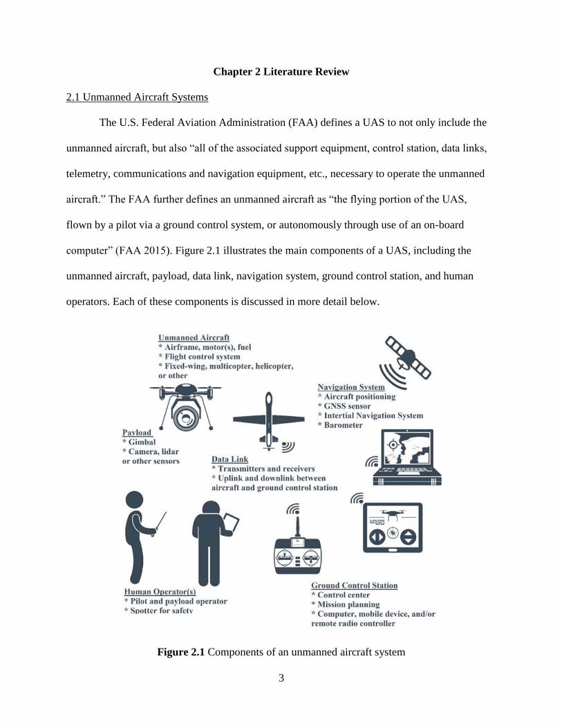
Chapter 3 Experimentation
To begin evaluating the use of UAS for inspecting bridges, a small quadcopter was flown
along a large bridge in western Oregon. The objective of the flights was to investigate its
capability of acquiring imagery that a bridge inspector could use to supplement an inspection.
Imagery of the following items on the bridge were collected for the following purposes:
• Connections – investigate the condition of bolts, rivets, possible pack rust, etc.
• Bearings – evaluate alignment, possible movement, bulging or tearing, etc.
• Joints – look for leakage, concrete spalling, steel section loss, cracking, etc.
• Banks – view conditions upstream and downstream of the bridge, search for erosion,
scour
• Other structural members in locations that are difficult to physically access
3.1 Bridge Site for Test Inspection
The UAS flights were conducted along the Independence Bridge, a deck-plate girder
bridge over the Willamette River on River Road South, Marion County, Oregon (see Figure 3.1).
The Independence Bridge is rated as a “large bridge” and is under the responsibility of the
Marion County, Oregon, Bridge Inspection program. It was originally constructed in 1951 and
rehabilitated in 1985. It has a total length of 675.4 m, longest span of 46.3 m, total deck width of
7.9 m, and total deck area of 2,787 square meters. Although the deck, superstructure, and
substructure appear to be in good condition, the bridge is fracture critical (i.e., failure of a steel
member would cause a portion of or the entire bridge to collapse).
25
Figure 3.1 Independence Bridge over the Willamette River, Oregon
3.2 Unmanned Aircraft System for Test Inspection
A DJI Phantom 3 Pro multicopter equipped with a gimballed camera capable of
collecting ultra-high-definition 4k video and 12 megapixel photography was selected for the tests
(figure 3.2). Multicopters are ideal for inspections because they are easy to maneuver, can hover
in place, allowing the operator to point the camera at features of interest, and are capable of
vertical take-offs and landings. The Phantom was chosen simply because it was the only
multicopter available to the project team and authorized by a COA from the FAA for this
experiment. The Phantom is also a popular system for hobbyists and some engineering
companies. However, the team recognizes that numerous other systems are available on the
market, and some may be better suited for performing structural inspections.
26
Figure 3.2 DJI Phantom 3 Pro, Pilot, and controller
3.3 Mission Operations
Several UAS flights were conducted on September 21, 2015. During each flight, the pilot
used first-person view technology for positioning the aircraft within 3 to 5 meters of the bridge
girders, and a visual observer maintained line-of-sight with the aircraft. First-person view video
was broadcast in real time to an Apple iPad Mini tablet mounted on top of the radio frequency
flight controller (figure 3.2). While hovering close to the girders, the pilot rotated the pitch up
and down on the gimballed camera and captured the 4k video. The aircraft was then slowly
flown parallel to the girder to the next hovering point, and additional video was captured in the
same manner. The first-person view camera was helpful for navigating the aircraft while
ensuring that video was acquired of desired features of the bridge. In addition, a bridge inspector
looked at the video feed in real time and occasionally asked the pilot to adjust position in order to
capture more imagery of interesting parts on the bridge. Every 15 minutes, the Phantom was
landed and batteries were swapped.
27
Chapter 4 Results and Discussion
The UAS successfully collected 55 minutes of ultra-high-definition video of both the
upstream and downstream sides of the bridge superstructure and substructure. This video is
available from the first author upon request. Although the video is more useful for evaluating
the utility of the UAS for inspecting the bridge, some still imagery was extracted from the video
(figures 4.1 to 4.7) in order to present some examples of the results in this report. These images
show some of the capabilities of UAS technology for evaluating the conditions of bearings,
connections, and joints on the bridge. Some discussion of the results of this experiment are also
given in Gillins et al. (2016). Figure 4.1 shows a bearing and joint on the bridge with some
leakage. The image shows that tar from a previous repair on the deck had leaked and pooled on
top of the concrete support tower. Figure 4.2 presents some of the bolts and bolt patterns at the
joints of steel members that could be analyzed for possible rust. Some cracking of a concrete
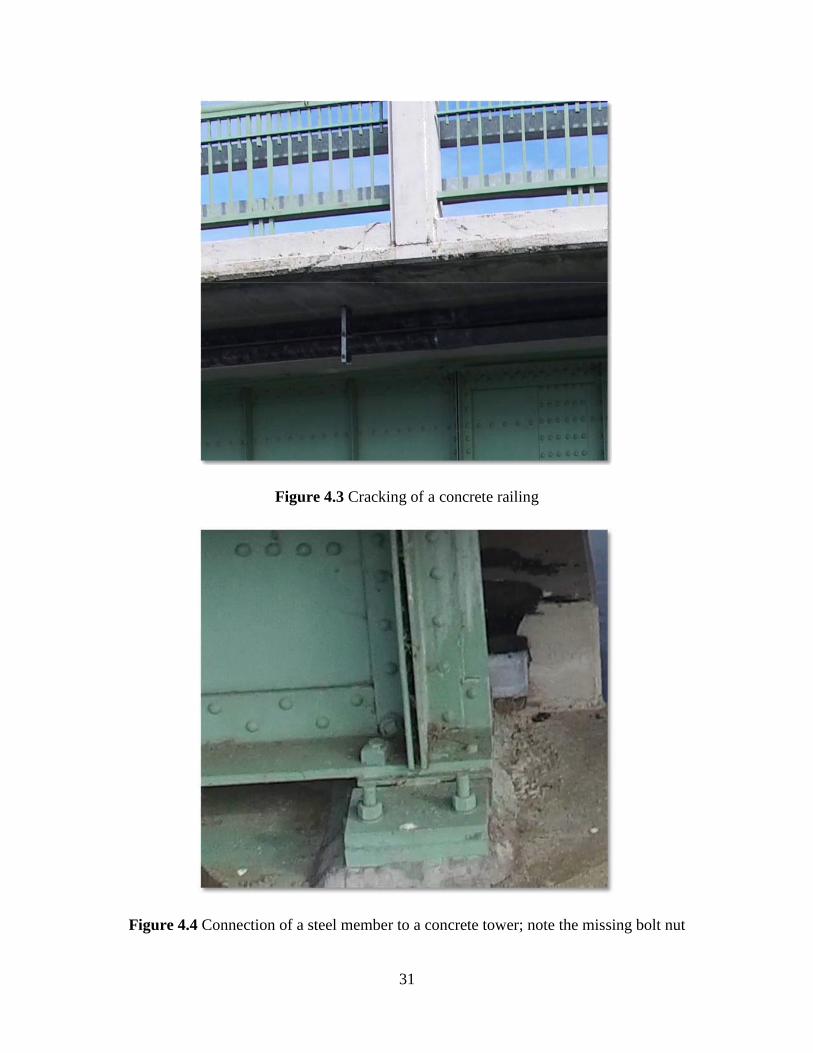
guard rail is evident in figure 4.3. Figure 4.4 depicts an important connection between two of
the steel girders on the bridge. Figure 4.5 shows the bearing of a steel beam on a concrete tower,
and it appears that a nut is missing on one of the bolts in the connection. Efflorescence was
evident on many of the concrete towers directly beneath the steel beams (e.g., figure 4.6).
In addition to collecting video of the bridge, the aircraft was also flew along the banks of
the river on both the upstream and downstream sides of the bridge. Flying and capturing video of
the banks was quite simple (especially when compared to flying in close proximity to the
bridge), and it enabled the inspector to quickly assess and document any possible erosion issues
near the bridge. During the flights of the banks of the river, the aircraft was flown at a speed of
approximately 1-3 meters per second. This speed was chosen because it simulates the
approximate speed at which a human could walk the banks and look for potential problems.
29
Figure 4.1 Evidence of a leaking joint
Figure 4.2 Example imagery of bolt patterns at steel connections
30
Figure 4.3 Cracking of a concrete railing
Figure 4.4 Connection of a steel member to a concrete tower; note the missing bolt nut
31
Figure 4.7 Bank of the river upstream of the bridge
Although beneficial video was captured of the bridge and the surrounding area, the team
noticed several challenges worth future research and development. The following discusses
some of the identified challenges and recommends some strategies for alleviating them.
4.1 Resolution
Bridge inspectors need very high-resolution imagery in order to evaluate the condition of
many of the small details on the bridge, such as each of the bolts and nuts at each joint. The
need for high resolution imagery is further compounded during an in-depth inspection, at which
the Bridge Inspector’s Reference Manual requires the inspector to view elements of the bridge
at an “arm’s length” standoff distance (Ryan 2008). As a brief discussion of this challenge, in
bright light Blackwell (1946) estimated the resolution of the human eye as 0.7 arc-minutes. For
an average human, arm’s length is approximately 63.5 cm. For small angles, the following
simple relationship enables estimation of spatial resolution as a function of angular resolution:
33
S R (4.1)
where S = the distance subtended at a standoff distance R by an arc of θ in radians. Setting R =
635 mm and θ = 0.7 arc-minutes, the spatial resolution of a human eye at arm’s length is
estimated as only 0.1 mm.
Acquiring imagery with this level of spatial resolution is quite difficult with the
consumer-grade cameras that are typically mounted on a UAS. For example, the resolution of the
ultra-high-definition video recorded by the camera mounted on the Phantom 3 Pro is up to 4096
x 2160 pixels. Its camera sensor has a width of 6.17 mm and a focal length of 3.6 mm. The
spatial resolution can be estimated by these camera parameters by the following relationship:
S SW R
(4.2) f PW
where SW = sensor width, R = standoff distance, f = the focal length, and PW = the width of the
image in pixels.
During the flights, the closest standoff distance of the aircraft from the bridge was
roughly 3 meters. Setting R = 3000 mm in Eqn. 4.2 and PW = 4096 pixels, the spatial resolution
(S) is estimated to equal 0.73 mm. This resolution is much coarser than the resolution of the
human eye at arm’s distance.
Of course, flying closer to the structure increases the likelihood of a crash. One possible
solution is to use a camera with a larger sensor focal length and/or a camera equipped with an
optical zoom. A zoom feature may enable collection of higher-resolution imagery without the
need to fly so close to the structure.
34
4.2 Obstructions
Because of the need to collect high resolution imagery as discussed above, operators
must fly the UAS very close to the structure. However, at short standoff distances, the structure
may obstruct or degrade satellite signals. If observers are attempting to fly underneath a
structure (e.g., beneath a bridge deck), the satellite signal may be completely blocked. GNSS
sensors are commonly installed on a UAS for assisting the operator during flight. When flying a
multicopter, GNSS enables the aircraft to hover in place. GNSS is also used to navigate the
aircraft during pre-programmed Waypoint-Assisted Missions. When a UAS is flown underneath
or in close-proximity to the bridge, the satellite signals may not be reliable. Other flight-
assistance sensors are needed to reduce the reliance on GNSS for positioning and navigation.
Some aircraft are equipped with ultrasonic sensors that can be used to detect obstacles or hold
the aircraft at a fixed distance from a structural member.
Inspecting the underside of the bridge deck presents another challenge. For some
aircraft, like the Phantom 3 Pro, the camera is mounted beneath the rotors. Thus, the camera
cannot be pointed to capture imagery directly above the aircraft. A UAS equipped with a front-
mounted camera is more useful for capturing imagery beneath structures.
4.3 Wind
Some of the small UAS are lightweight, and strong wind gusts have the potential to
push the aircraft in unexpected directions. The Phantom 3 Pro only weighs 1.28 kg, and a 12
knot wind gust will affect it during flight. This issue is complicated by flying in close proximity
to a bridge. Bridges over wide rivers or canyons are commonly in natural
“wind tunnels,” and complicated wind eddies can form near the bridge. A heavier multicopter
is better suited for flying through strong wind gusts.
35
4.4 Lighting
Digital cameras are passive sensors, and poor lighting degrades the quality of the
imagery. During certain times of day, especially near sunrise and sunset, shadows or overly
bright spots may be on the bridge. Use of a camera in poor lighting can result in over- or under-
exposed imagery that may make it difficult to find defects on the bridge. Typically, flights
during midday or in overcast weather are best for optimizing the natural lighting conditions.
However, lighting is generally always poor when imagery is captured underneath the bridge
deck. Flash lights or head beams could help alleviate this issue. In addition, computer science
tools might be used to post-process and enhance the quality of the UAS-derived imagery.
Additional tools need to be developed to for accounting for poor lighting conditions. Real-time
tools need to be developed for changing the aperture size of the camera during flight.
36
Chapter 5 Conclusions
UAS has great potential for reducing some of the dangers and costs associated with a
bridge inspection. Further, as documented in this report, UAS can be beneficial for a number of
additional transportation engineering-related problems, such as for monitoring traffic, inspecting
construction sites, surveying and mapping, performing roadside condition inventorying, etc.
In this study, a small quadcopter was flown to collect ultra-high-definition video of a large
bridge in Independence, Oregon. A number of minor bridge defects could be noted in the
imagery, including rust, missing nuts, efflorescence, cracks, and spalling. The videos could be
used to satisfy many of the routine and initial bridge inspection requirements of the AASHTO
Bridge Inspection Manual (AASHTO, 2011). The imagery may also be useful for in-depth
inspections; however, in-depth inspections sometimes require probing and scraping that cannot
be accomplished with UAS. In addition, in-depth inspections require the inspector to be at arm’s
length of the bridge. Obviously, a UAS does not satisfy this requirement, but imagery collected
from a UAS can be of high resolution.
A few challenges were noted in this report. Perhaps the greatest challenge involves
capturing imagery with a UAS with sufficient resolution for an inspection. At arm’s length, the
human eye has a spatial resolution approximately equal to 0.1 mm. Even within 3 meters of the
bridge, the approximate spatial resolution of the high-definition camera onboard the quadcopter
in this experiment was 0.7 mm. Flying even closer to the bridge is difficult because of
complicated wind eddies that can potentially push the aircraft into the structure. However, this
problem could be alleviated by flying a heavier aircraft equipped with a camera with a larger
sensor size and an optical zoom. Future research remains to investigate other UAS platforms for
bridge inspection.
37
It is worth noting that the authors have been awarded a two-year grant from the Oregon
Department of Transportation (ODOT) to conduct additional field tests. In this grant, the team
will fly additional bridges using other sizes of multicopters and cameras. In addition, the team
will acquire imagery during official bridge inspection(s) conducted by ODOT. The costs and
benefits of these tests will be documented in a future ODOT research report.
38
References
American Association of State Highway and Transportation Officials (AASHTO) (2011). The
Manual For Bridge Evaluation Second Edition.
ASCE 2013
Barfuss, S.L., A. Jensen, and S. Clemens, (2012). Evaluation and Development of Unmanned
Aircraft (UAV) for UDOT Needs. No. UT-12.08: http://trid.trb.org/view.aspx?id=1147966
(last date accessed: 3 Dec 2015).
Blackwell, H.R. (1946). “Contrast Thresholds of the Human Eye”. J. of the Optical Society
of America. 36(11), 624-643
Brooks C., et al (2015). Evaluating the Use of Unmanned Aerial Vehicles for Transportation
Purposes., Michigan Tech Research Institute, Ann Arbor, Michigan.
CTC & Associates LLC (2014). “The Use of Unmanned Aerial Systems for Steep Terrain
Investigations. Caltrans Division of Research.
ConnDOT. (2015). “CTDOT to Test Unmanned Aerial Vehicle System (UAV) for Bridge
Inspection.” Connecticut Department of Transportation News Release.
<http://www.ct.gov/dot/cwp/view.asp?a=1373&Q=574468> (last date accessed: 18 Dec
2015).
Ellenberg A., L. Branco, A. Krick, I. Baroli, and A. Kontsos (2014). “Use of Unmanned
Aerial Vehicle for Quantitative Infrastructure Evaluation.” J. Infrastruct. Syst., ASCE.
Eschmann C., C.-M. Kuo, C.-H. Kuo, and C. Boller (2013). “High-Resolution Multisensor
Infrastructure Inspection with Unmanned Aircraft Systems.” International Archives of the
Photogrammetry, Remote Sensing and Spatial Information Sciences. 1(2), 125-129.
Estes C. (2014). Unmanned Aircraft Use in North Carolina. Report to the Joint Legislative
Oversight Committee on Information Technology Joint Legislative Transportation
Oversight Committee Fiscal Research Division.
Federal Aviation Administration (FAA), (2015). “Fact Sheet – Unmanned Aircraft Systems (UAS).” FAA, < https://www.faa.gov/news/fact_sheets/news_story.cfm?newsId=14153 >
(last date accessed: 3 Dec 2015).
Federal Aviation Administration (FAA), (2016). “Fact Sheet – Small Unmanned Aircraft
Regulations (Part 107).” FAA, <
https://www.faa.gov/news/fact_sheets/news_story.cfm?newsId=20516 > (last date
accessed: 12 Oct 2016).
Frierson, T., (2013). Use of Unmanned Aerial Vehicles for AHTD Applications. Arkansas State
Highway and Transportation Department Report Number TRC1104. Arkansas State
Highway and Transportation Department, 28 pp.
39
Gillins, M.N., Gillins, D.T., and Parrish, C., (2016). Cost-Effective Bridge Safety Inspection
using Unmanned Aircraft Systems (UAS). Proceedings of Geotechnical and Structural
Engineering Congress 2016, ASCE, Phoenix, AZ, 10 pp.
GPO 2012
Gu, Y., (2009). Evaluation of Remote Sending Aerial Systems In Existing
Transportation Practices. West Virginia Department of Highway.
Hallermann N., and Morgenthal G. (2013). “Unmanned Aerial Vehicles (UAV) for the
Assessment of Existing Structures.” IABSE Symposium Report. IABSE 101(14).
Hallermann N., Morgenthal G., and Rodehorst V. (2014). “Vision- Based deformation monitoring of
large scale structures using Unmanned Aerial Systems.” IABSE Symposium Report, IABSE.
Hart, W.S., and Gharaibeh, N.G., (2011). Use of Micro Unmanned Aerial Vehicles in Roadside
Condition Surveys, Proceedings of the T & DI Congress 2011, ASCE, Chicago, IL, p.
81– 92.
Irizarry, J., and Johnson, E.N., (2014). Feasibility Study to Determine the Economic and
Operational Benefits of Utilizing Aerial Vehicles (UAVs). Georgia DOT Research
Project Report No. FHWA-GA-1H-12-38, Georgia Department of Transportation, 158
pp.
Judson, F., (2013). Unmanned Aircraft Systems at the Ohio Department of Transportation,
2013 AASHTO GIS for Transportation Symposium: http://www.gis-
t.org/files/TthrL.pdf (last date accessed: 3 Dec 2015).
Khan F. et al. (2015). “Investigation on Bridge Assessment Using Unmanned Aerial Systems.”
Structures Congress 2015.
Lovelace, B., (2015). Unmanned Aerial Vehicle Bridge Inspection Demonstration Project,
Minnesota DOT Report No. MN/RC 2015-40, Minnesota Dept. of Transportation, 214 pp.
McCormack, E.D., (2008). The Use of Small Unmanned Aircraft by the Washington State
Department of Transportation, Research Report, Agreement T4118, Task 04, Unmanned
Aerial Vehicles. Washington State Transportation Center (TRAC), Seattle, Washington.
Otero L., et al (2015). “Proof of Concept for Using Unmanned Aerial Vehicles for High
Mast Pole and Bridge Inspections”, Florida Institute of Technology, Department of
Engineering Systems, Melbourne, Florida.
Pajares, G., (2015). Overview and Current Status of Remote Sensing Applications Based on
Unmanned Aerial Vehicles (UAVs). Photogrammetric Engineering & Remote Sensing,
ASPRS, 81(4): 281-329.
40
Ryan, T.W., Mann, J. E., Chill Z. M., Ott B. T. (2008). “Bridge Inspector’s Reference
Manual (BIRM).” 984 pp.
Sa I., S. Hrabar, and P. Corke (2015). “Outdoor Flight Testing of a Pole Inspection UAV
incorporation High-Speed Vision.” Field and Service Robotics, 105(3) 107-121.
Vaghefi K. et al. (2012). “Evaluation of Commercially Available Remote Sensors for Highway
Bridge Condition Assessment.” Journal of Bridge Engineering, 17(6), 886-895.
41