Prepared by: Public Works Department Water Utilities Division Water Resources Hydrology 307 W. Guadalupe Road Tempe, Arizona 85018 28 February 2017 GROUNDWATER RESOURCES SUMMARY REPORT CITY OF TEMPE ASR WELL RW-1 KEN MCDONALD GOLF COURSE ASR PROGRAM
Transcript
Prepared by:
Public Works Department
Water Utilities Division
Water Resources Hydrology
307 W. Guadalupe Road Tempe, Arizona 85018
28 February 2017
GROUNDWATER RESOURCES SUMMARY REPORT
CITY OF TEMPE ASR WELL RW-1 KEN MCDONALD GOLF COURSE ASR PROGRAM
BLANK PAGE
EXECUTIVE SUMMARY
A summary report for each production and artificial recharge well operated and/or managed by the City of Tempe (COT) has been prepared with the intent of summarizing well permitting, construction, operation and maintenance throughout the life of the well. These reports are living documents, intended to be regularly updated as new data is discovered or developed, or when wells are modified, tested or rehabilitated.
This report summarizes collected information and data for Artificial Storage and Recovery (ASR) well RW-1. RW-1 was initially drilled in 2011, and has been used for ASR activities since July 2014 when potable water has been available for recharge and storage. The well is remotely operated via the City’s SCADA system from the JGM WTP. Field staff is assigned to maintain the well as directed by WUD water managers. Water quality sampling and water level monitoring to meet ADWR permit requirements are conducted by staff from the Environmental Division of WUD.
RECORD OF REVISIONS
Revision # Date Name Summary
1 28 Feb 2017 DEA Updated from EK and PB comments, added records, added quarterly report as Appx H.
BLANK PAGE
City of Tempe Well # RW-1 – KMGC ASR 28 February 2017
Table 4 – Backwash Line Hydraulic Design Data ......................................................................... 6
Table 5 – Monitoring Well Summary ........................................................................................... 10
Table 5 - KMGC ASR RW-1 Summary ....................................................................................... 13
Table 5- KMGC ASR RW-1 Summary (Continued) .................................................................... 14
Table 6 - KMGC ASR RW-1 Action Items ................................................................................... 15
Table 7 - KMGC ASR RW-1 Activity Tracking ............................................................................ 15
LIST OF APPENDICES
Appendix A - Well Location Information .................................................................................. A-1
Appendix B - Well Drilling and Construction Records ............................................................. B-1
Appendix C - Well and Aquifer Testing Records ..................................................................... C-1
Appendix D - Water Quality Records ....................................................................................... D-1
Appendix E – Well Rehabilitation Records .............................................................................. E-1
Appendix F – ADWR and ADEQ Permits and Records ............................................................ F-1
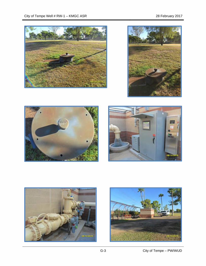
Appendix G – Representative Site Photos .............................................................................. G-1
Appendix H – Additional Data Summary Information .............................................................. H-1
City of Tempe Well # RW-1 – KMGC ASR 28 February 2017
vii City of Tempe – PW/WUD
LIST OF ACRONYMS AND ABBREVIATIONS
ADWR Arizona Department of Water Resources
AF Acre-Feet
AMSL Above Mean Sea Level
APN Assessor’s Parcel Number
APP Aquifer Protection Permit
ASR Aquifer Storage and Recovery
AWQS Arizona Aquifer Water Quality Standards
BGS Below Ground Surface
COT City of Tempe
FS Feasibility Study
gpm Gallons Per Minute
GWSI Groundwater Site Inventory
HPU Hydraulic Power Unit
JGM WTP Johnny G. Martinez Water Treatment Plant
KGS Kyrene Generating Station
KMGC Ken McDonald Golf Course
LUST Leaking Underground Storage Tank
MGD Million Gallons per Day
MW Mega Watt
OIT Operator Interface Terminal
PLC Programmable Logic Controller
POE Point of Entry
PRV Pressure Reduction Valve
PW Public Works
RCRA Resource Conservation and Recovery Act
City of Tempe Well # RW-1 – KMGC ASR 28 February 2017
viii City of Tempe – PW/WUD
SC Specific Capacity
SCADA Supervisory Control and Data Acquisition
SRP Salt River Project
STWTP South Tempe Water Treatment Plant
T Transmissivity (in gpd/ft or ft2/day)
USF Underground Storage Facility
WRF Water Reclamation Facility
WUD Water Utilities Division
City of Tempe Well # RW-1 – KMGC ASR 28 February 2017
1 City of Tempe – PW/WUD
1.0 INTRODUCTION
The City of Tempe’s (COT) groundwater management program is managed by the Public Works Department (PW), Water Utilities Division (WUD). WUD operates one Aquifer Storage and Recovery (ASR) well, 14 potable groundwater wells permitted as recovery wells with ADWR and used as drinking water sources and supplemental water supply for the municipal water system, and a number of additional groundwater wells used for irrigation, water recovery, and water exchange purposes (Tempe 2017). COT also cooperatively accesses 4 wells with SRP (Wells 14, 17, 18 and 19).
The City can withdraw a limited amount of safe-yield groundwater supplies from its potable wells each year. Water stored in groundwater aquifers through underground storage projects can also be recovered through city wells that are permitted as recovery wells. The use of groundwater from Tempe’s municipal production wells over the last decade has ranged from less than 1% to about 11% of Tempe’s total municipal water use in a normal year. During periods of prolonged drought, with reductions in available surface water supplies, Tempe’s use of groundwater may be increased within allowable limits until watershed conditions improve. The Arizona Department of Water Resources (ADWR) Assured Water Supply Rules allow for drought exemption groundwater pumping only during periods when normal surface water supply allocations have been reduced due to drought conditions (Tempe 2012).
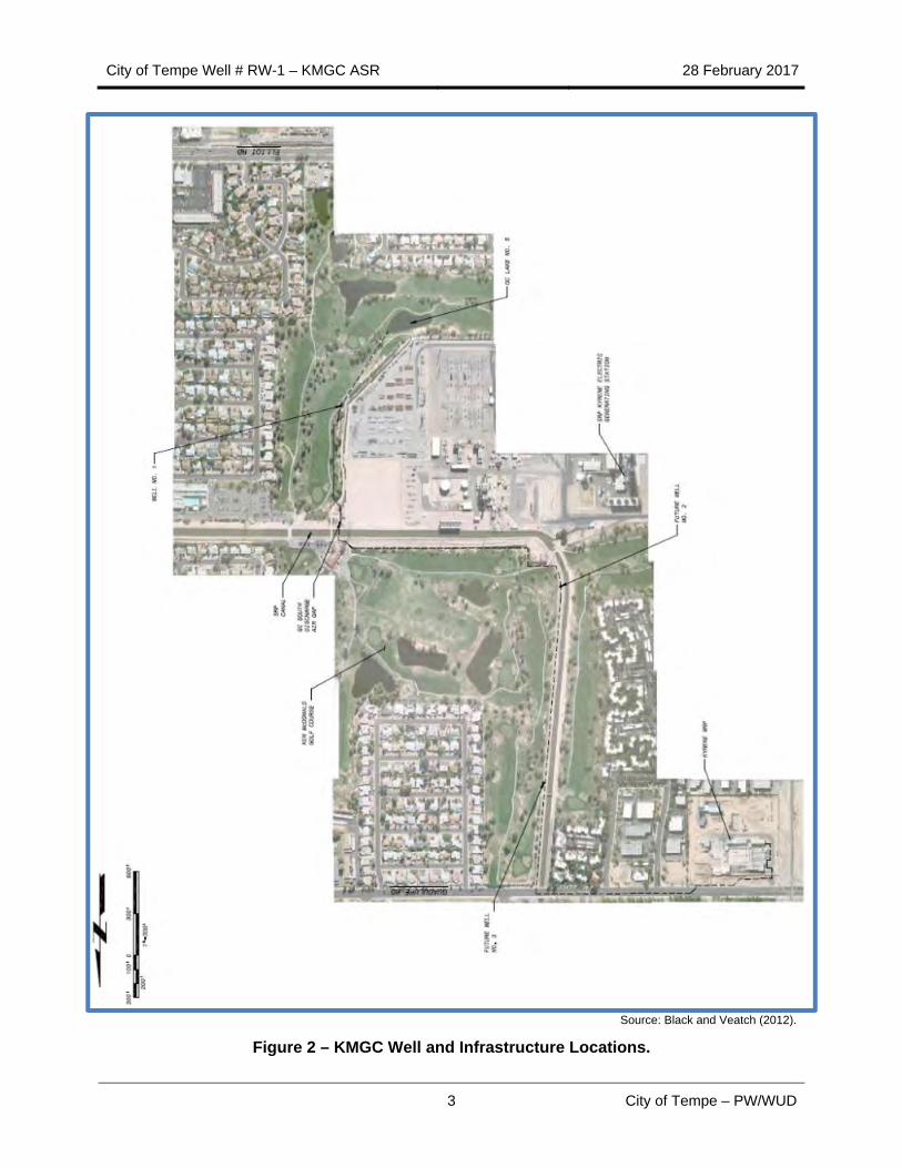
The general locations of all City wells are illustrated on Figure 1. The Ken McDonald Golf Course (KMGC) ASR well designated RW-1 is located at the Ken McDonald Golf Course in south Tempe, in Section 10 Range 22 East, Township 1 South; south of East Guadalupe Road, east of South Kyrene Road and west of South Rural Road. Figure 2 illustrates the location of the KMGC ASR well and related infrastructure (Black and Veatch 2011). Figure 3 illustrates locations of the KMGC ASR well, five City monitoring well locations and other wells within the general vicinity as reported by ADWR’s Groundwater Site Inventory (GWSI) online database (ADWR, 2016).
City of Tempe Well # RW-1 – KMGC ASR 28 February 2017
2 City of Tempe – PW/WUD
Source: City of Tempe, 2016.
Figure 1 – City of Tempe Water Resources Infrastructure.
City of Tempe Well # RW-1 – KMGC ASR 28 February 2017
3 City of Tempe – PW/WUD
Source: Black and Veatch (2012).
Figure 2 – KMGC Well and Infrastructure Locations.
City of Tempe Well # RW-1 – KMGC ASR 28 February 2017
4 City of Tempe – PW/WUD
Source: ADWR (2017).
Figure 3 – KMGC ASR Well and Monitoring Well Locations.
1.1 Recharge Well Hydraulics
Recharge well hydraulics were evaluated in 2011 by Black and Veatch, and were based on overall recharge flows as shown in Table 1. In the initial phase of the project, only Well No. 1 was developed, with a maximum recharge capacity of 1.70 Million Gallons per Day (MGD).
Table 1 – Recharge Flow Design Summary
Design Conditions Well No. 1 Well No. 2 Well No. 3 Total
Current, MGD 1.7 0 0 1.7
Future, MGD 1.5 1.5 1.5 4.5*
* Based on 2011 Predicted Flow (Black and Veatch, 2011).
Individual recharge well hydraulics was analyzed in 2011 using the flow criteria shown in Table 2. To maintain minimum pressure at the recharge control equipment, an upgrade to the existing Pressure Reduction Valves (PRV’s) at the Kyrene Water Reclamation Facility (WRF) was required.
City of Tempe Well # RW-1 – KMGC ASR 28 February 2017
5 City of Tempe – PW/WUD
Table 2 – 2011 Recharge Design Flows
Phase 11 Phase 22
Design Flow, MGD 1.7 4.5 3
Number of Wells 1 3
Delivery Line Size, in 12 12
Min Velocity, FPS 3.35 4 3.35
Max Velocity, FPS 7.54 5 8.86 6
Notes:
1. Phase 1 includes recharge flow to Well No. 1 (1.7 MGD).
2. Phase 2 includes flows to 3 recharge wells (4.5 MGD).
3. 4.5 MGD is limited by the existing 12‐inch line and Kyrene effluent pumps capability.
4. Velocity of 1.7 MGD through main 12‐inch line.
5. Velocity of 1.7 MGD to a single well through well 8‐inch line.
6. Velocity of 4.5 MGD through main 12‐inch line.
Source: Black and Veatch (2011).
Table 3 – 2011 Recharge Design Flows
Criteria Value
Physical Well Parameters
Specific recharge capacity, gpm/ft 148.2
Depth to groundwater, ft 85 ft bgs
Casing diameter, in 20
Screen diameter, in 20
Screen setting depth (bottom), ft 160 ft bgs
Length of screen, ft 60 ft
Pump setting depth (bottom), ft 150 ft bgs
Rise at rated recharge capacity, ft Approximately 12 ft
Drawdown at backwash rated capacity, ft Approximately 14 ft
Well Equipment
Pump capacity, gpm 1500
Pump rated head, ft 115
Pump power, hp 60
Column pipe size, in 10
Rated recharge capacity, gpm 1200
Variable orifice valve size, in 8 inches
Source: Black and Veatch (2011).
City of Tempe Well # RW-1 – KMGC ASR 28 February 2017
6 City of Tempe – PW/WUD
Table 4 – Backwash Line Hydraulic Design Data
Item Value
Design Backwash Rates
Design Rate, gpm 1,500
Backwash Supply Pump
Number of Pumps 1
Pump rated head, ft 114
Discharge Size, in 10
Discharge Velocity, fps 6.03
Source: Black and Veatch (2011).
1.2 Recharge Well Summary
The recharge wells consist of a drilled well shaft, lined with casing and screening, and a submersible pump with discharge column and check valve. Just above the submersible pump and check valve is a special hydraulically actuated variable-orifice (V-Smart) valve that can be opened to regulate recharge flow or closed to allow the pump to discharge normally. Equipment at the surface consists of piping and valves for recharge flow as well as pumped flow, instrumentation, and controls.
Surface equipment is at grade. The schematic for a typical recharge well is shown below on Figure 4 (Black and Veatch, 2011). Recharge well equipment consists of a V-Smart valve, control cabinet consisting of the hydraulic pump and controls, programmable logic controller (PLC), operator interface terminal (OIT), electrical connections, and control interface. Appurtenances also includes surface piping assembly consisting of motor actuated valves and a bi-directional magnetic flowmeter. Supply piping to the well, column pipe, and backwash piping to the appropriate lake are also installed. (Black and Veatch, 2011).
City of Tempe Well # RW-1 – KMGC ASR 28 February 2017
7 City of Tempe – PW/WUD
Source: HydroSystems, Inc. (2011).
Figure 4 – ASR Well Schematic.
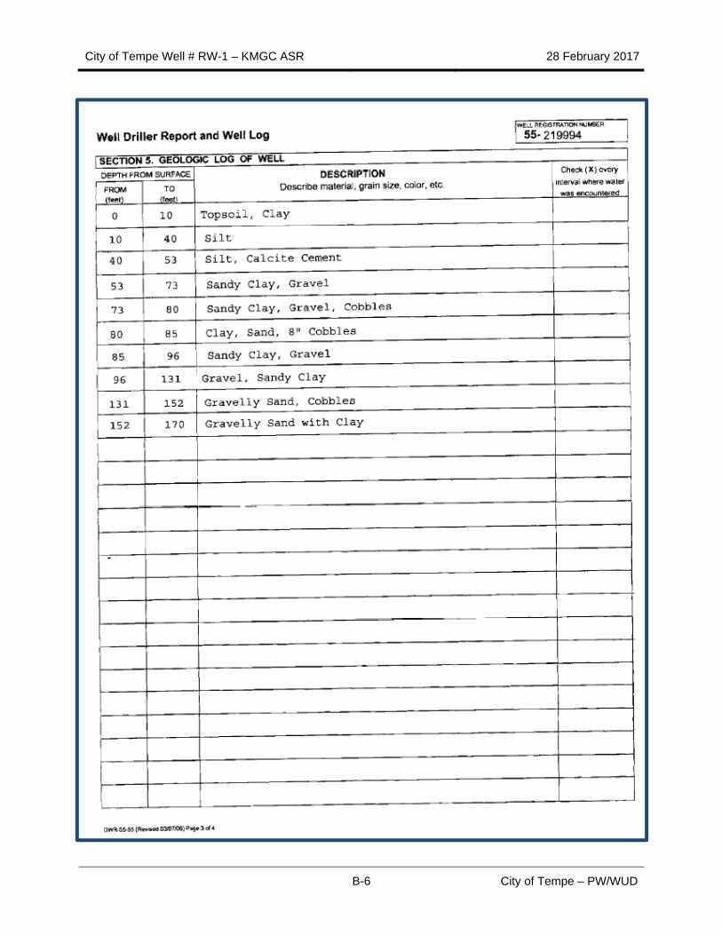
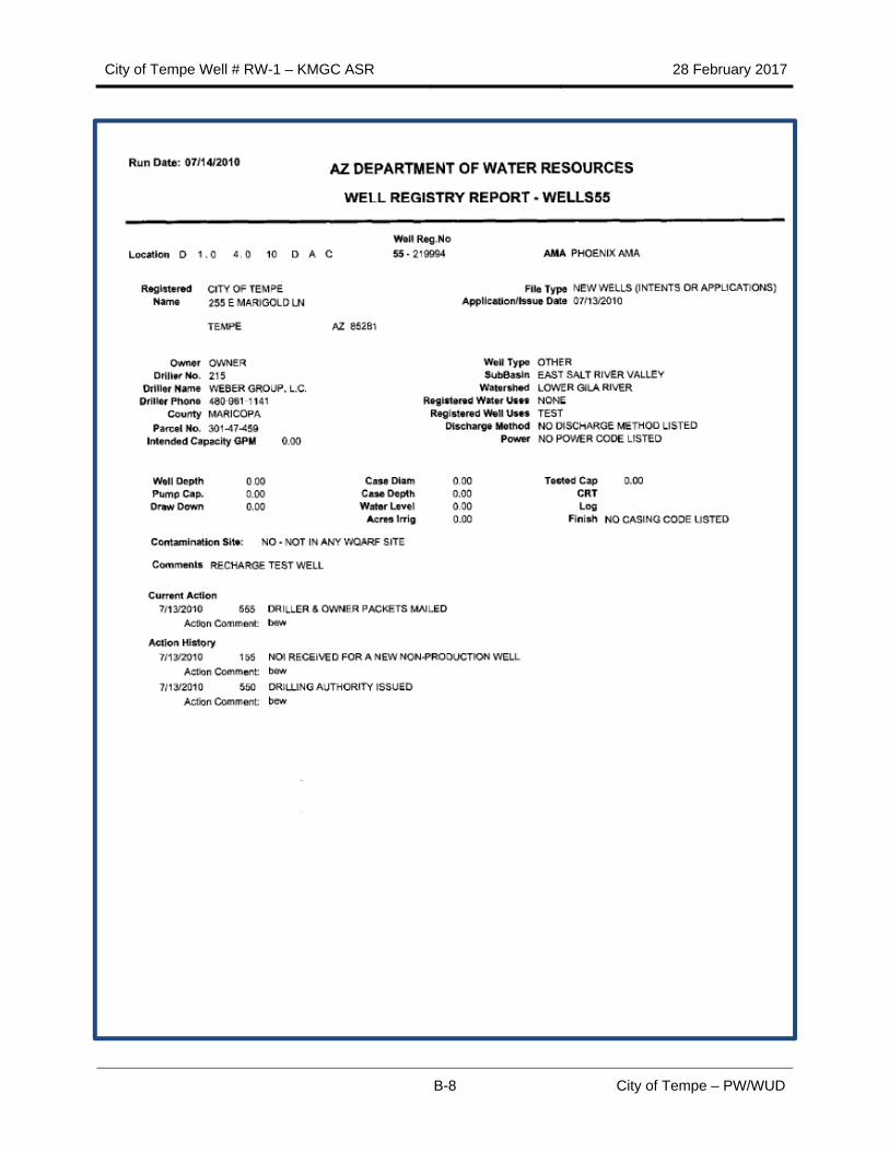
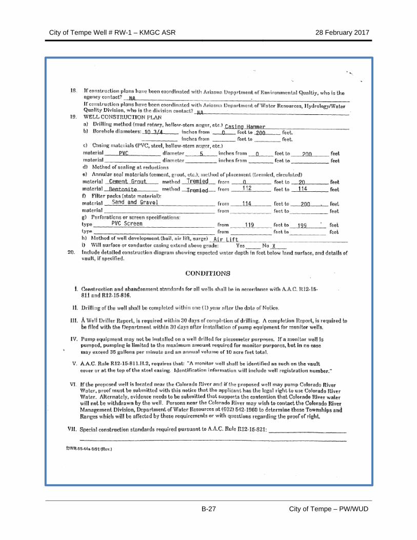
Weber Drilling was contracted by COT to drill and install ASR well RW-1. The steel conductor casing was drilled and installed 27 July 2010 to a depth of 39 feet bgs with one foot of casing above ground surface. The well was drilled using a cable tool drill rig between 10 August 2010 and 28 July 2010. The drill rig was equipped with a 20-inch-diameter drill bit, and the well was drilled to a depth 171 feet bgs (Hydro-Systems, Inc., 2011). The HSI report indicated that drilling was slow to a depth of about 53 feet bgs, at about 1 ft/hr due to the abundance of silt and clay. The drilling rate increased slightly below 53 feet, between seven and ten feet per day. Minor caving was encountered while drilling through sand and gravel intervals. Drilling continued until a total depth of 171 feet was reached. The last 20 feet of material, 151 feet to 171 feet, were penetrated at a higher drilling rate of ten feet per hour. Steel casing was advanced simultaneously with the drilling of the borehole. Well construction related data are summarized in Table 5.
City of Tempe Well # RW-1 – KMGC ASR 28 February 2017
8 City of Tempe – PW/WUD
1.3 Aquifer Testing
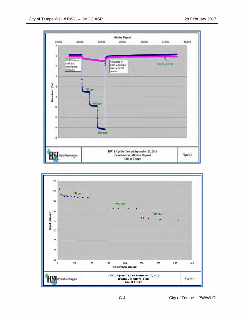
A stepped rate aquifer test was conducted on RW-1 September 20, 2010. This six -hour test pumped at rates of 750, 1,000 and 1,300 gpm for two hours per step. Water level measurements were recorded by a dedicated transducer installed in RW-1 three days before the test. Field personnel independently recorded water level measurements over the course of the test.
Ten to 15 minutes after the beginning of each pumping step, water levels drew down quickly to relative stability. At the end of the last step, at a maximum pumping rate of 1,300 gpm, drawdown was 14.3 feet. Specific Capacity (SC) at the end of the first step (750 gpm) was 113.7 gpm per foot of drawdown (gpm/ft). SC at the end of the second (1,000 gpm) and third (1,300 gpm) steps was 102.1 gpm/ft and 90.6 gpm/ft. These are large values, indicating a highly conductive and transmissive aquifer. (HSI, 2011).
At the end of the aquifer test, water levels recovered to within two inches of the initial static water level within 38 minutes. Recovery data was used to calculate transmissivity (T) of the aquifer at 272,712 gpd/ft (or 36,754 ft2/day). This high T value is consistent with observed drill cuttings between 60 and 160 feet, which are dominated by well-rounded pebbles and less abundant clean sand.
1.4 Injection Testing
Potable water was used for injection testing. Previous testing indicated that a possible flow of 900 gpm could be obtained with a pressure of 70 psi. Injection testing occurred 28 September 2010. The water level mounded, rising 2.6 feet initially, reaching a maximum level of +2.8 feet. The maximum pressure within the well was 14 psi. Flow rates varied between 410 and 420 gpm. The injection flow rate was increased in the well to 465 gpm generating a water mound of about +2.8 feet. Increases in flow rate could not be obtained due to the lack of well head pressure. (HSI, 2011).
1.5 RW-1 Well Equipping Summary
RW-1 is equipped with a 60 HP submersible electric pump, with the intake at 150 feet bgs, and a V-Smart valve above the pump. The V-Smart Valve is hydraulically actuated, near linear flow control device that permits adjustment of the flow rate using the Programmable Logic Controller/Supervisory Control and Data Acquisition (PLC/SCADA) system. At startup and during recharge, the valve is set in the closed position allowing the drop pipe to fill with water. Air in the pipe is evacuated through an air-vacuum valve at the wellhead, eliminating cascading water. Air entrainment can lead to air fouling, increased bio-fouling and calcite formation. Recharge rate is controlled using an electric hydraulic control valve with local and/or SCADA control. Flow is adjusted using a null loop, a dead band, a magnetic flow meter and the dynamic water level with a PLC to control water flow. Figure 5 diagrammatically illustrates operation of a typical V-Smart valve (ASR, 2016).
City of Tempe Well # RW-1 – KMGC ASR 28 February 2017
9 City of Tempe – PW/WUD
Source: ASR (2016).
Figure 5 – V-Smart Valve Operation Schematic
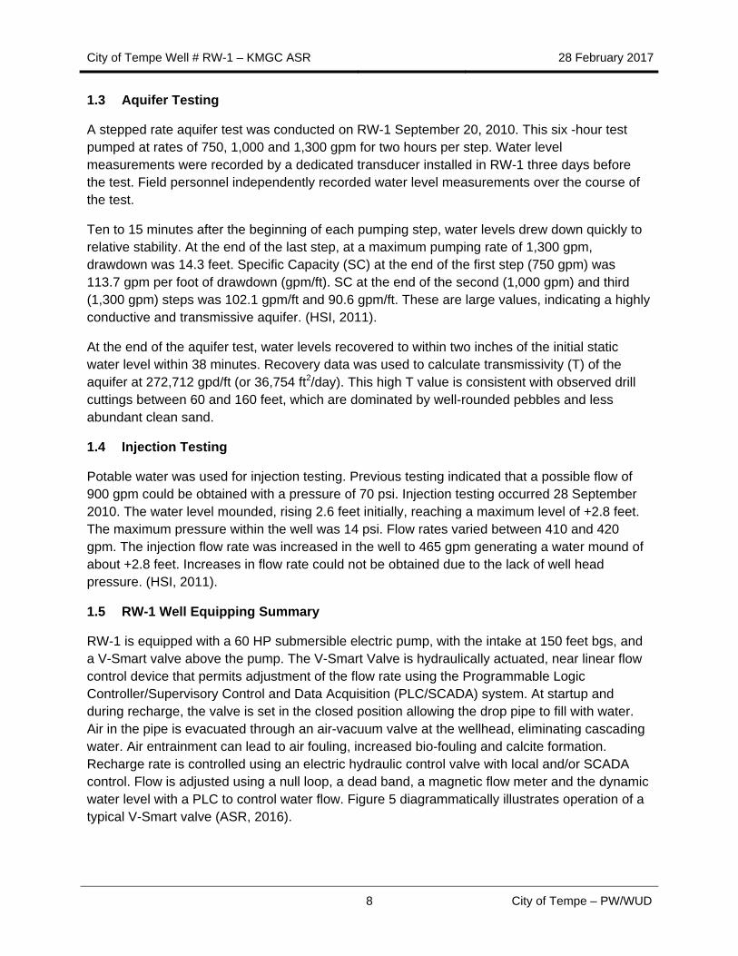
RW-1 utilizes an 8” multi-port V-Smart down hole control valve. Valve installation included two sets of continuous length dual line hydraulic hose connected to a Nema-3R enclosed hydraulic power unit (HPU). The HPU includes a front door mounted control panel with a local/remote selector switch, push buttons for local operation, pump run and open/closed lights. The valve has 8” female standard straight threads in both the upper and lower couplings. The valve is installed above the submersible pump and check valve, and threads onto to the male standard straight threads of the column pipe. Figure 6 illustrates the valve and hydraulic couplings prior to down hole installation. Figure 7 illustrates the discharge versus valve opening position.
Source: ASR (2016).
Figure 6 – V-Smart Valve and Hydraulic Couplers
City of Tempe Well # RW-1 – KMGC ASR 28 February 2017
10 City of Tempe – PW/WUD
Source: ASR (2016).
Figure 7 – Discharge versus Valve Opening
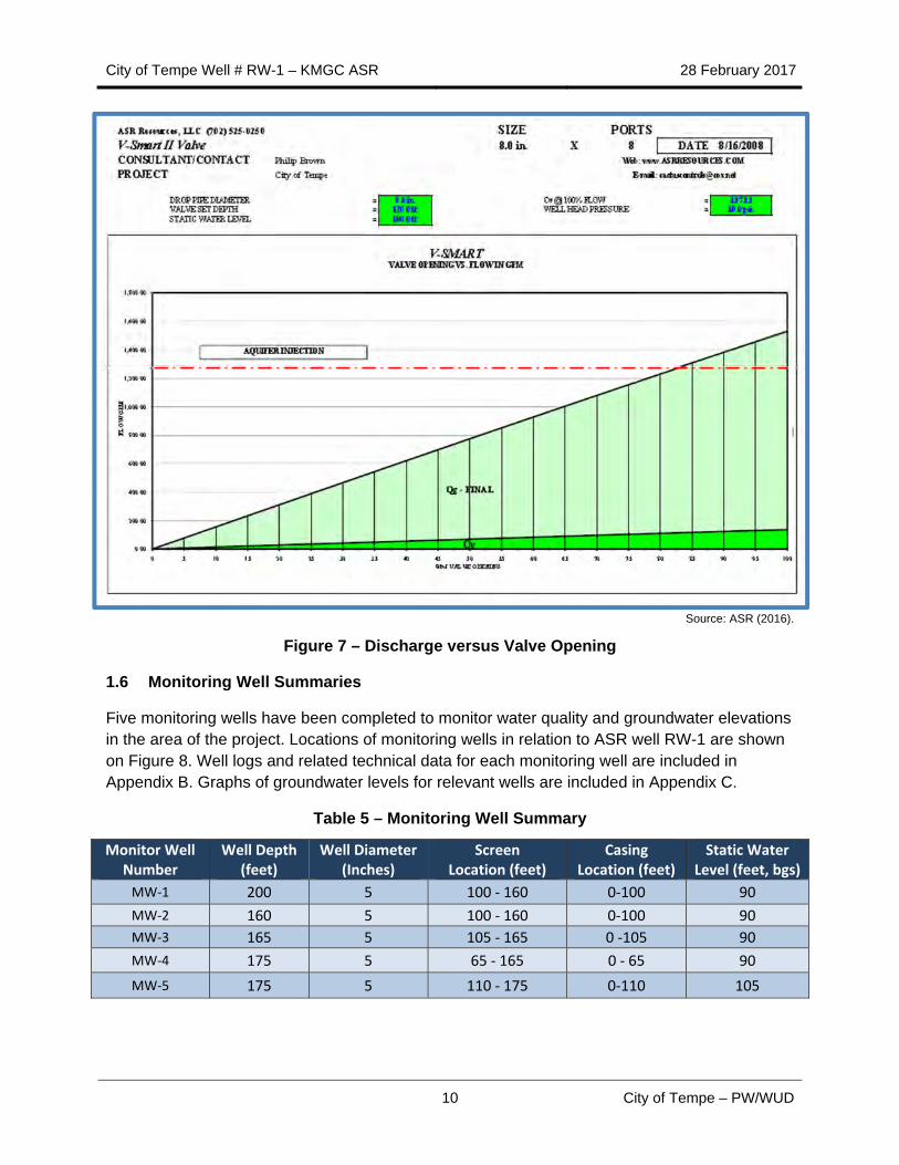
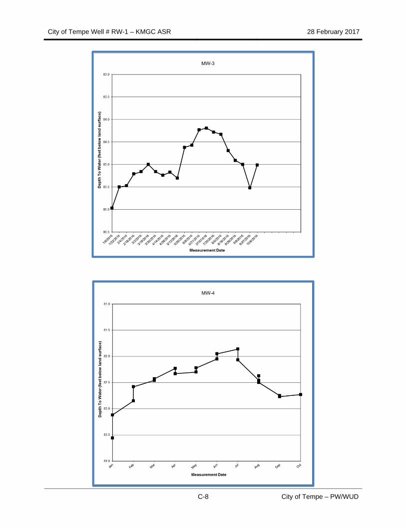
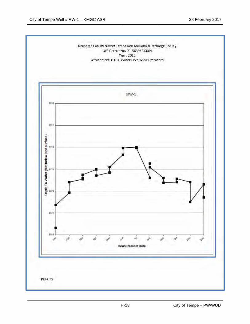
1.6 Monitoring Well Summaries
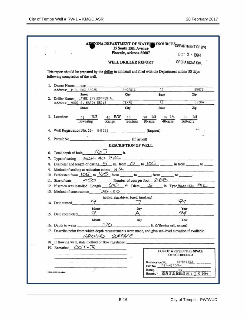
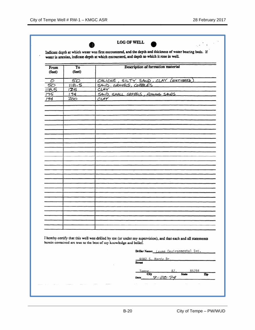
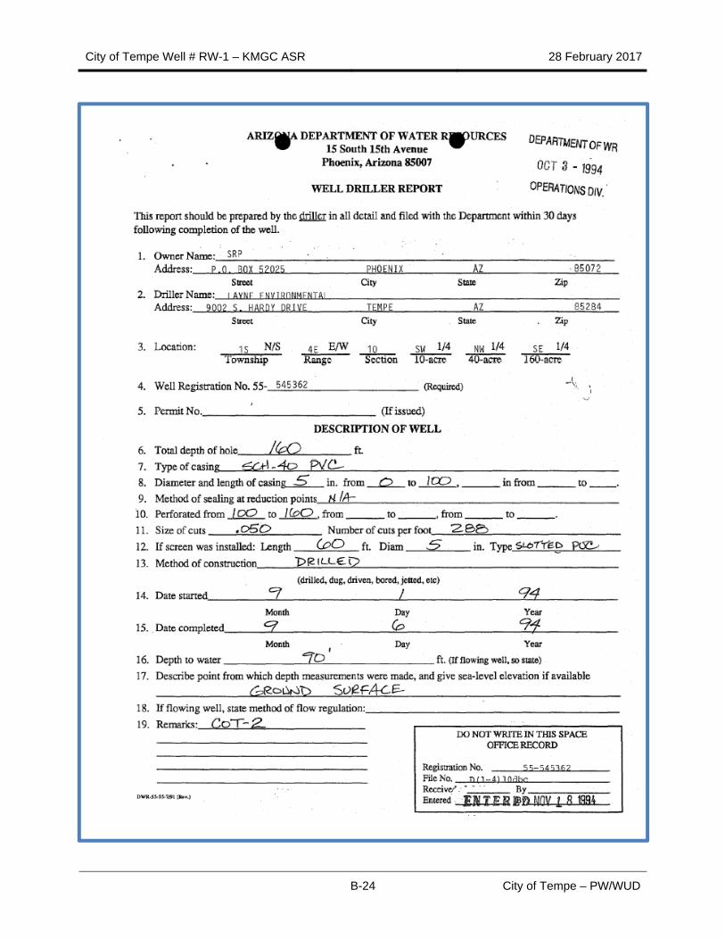
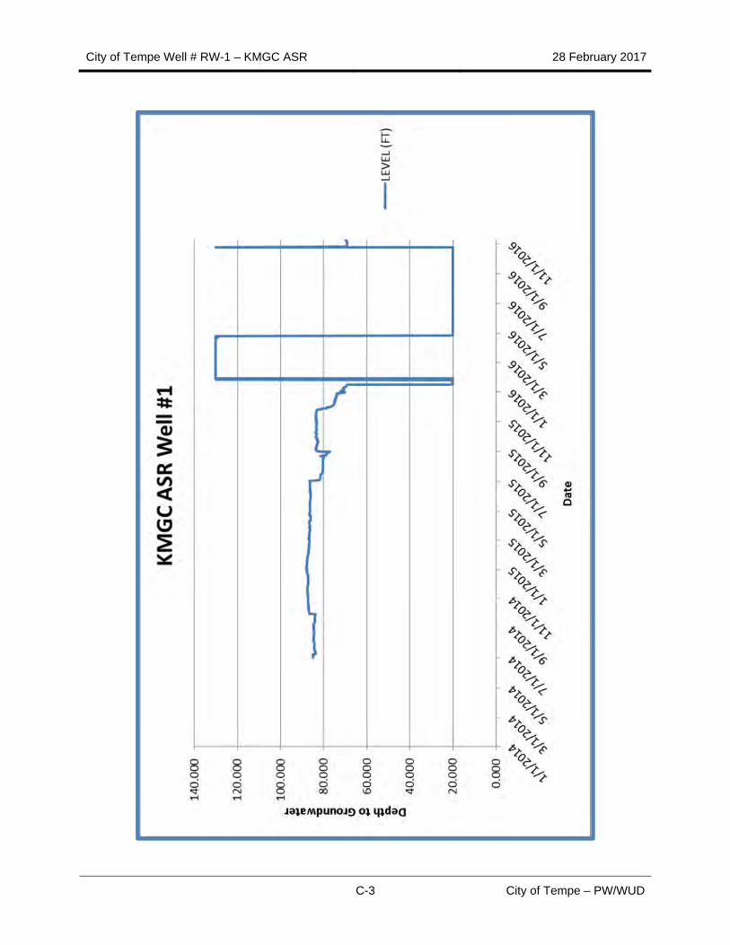
Five monitoring wells have been completed to monitor water quality and groundwater elevations in the area of the project. Locations of monitoring wells in relation to ASR well RW-1 are shown on Figure 8. Well logs and related technical data for each monitoring well are included in Appendix B. Graphs of groundwater levels for relevant wells are included in Appendix C.
Table 5 – Monitoring Well Summary
Monitor Well Number
Well Depth (feet)
Well Diameter (Inches)
Screen Location (feet)
Casing Location (feet)
Static Water Level (feet, bgs)
MW‐1 200 5 100 ‐ 160 0‐100 90
MW‐2 160 5 100 ‐ 160 0‐100 90
MW‐3 165 5 105 ‐ 165 0 ‐105 90
MW‐4 175 5 65 ‐ 165 0 ‐ 65 90
MW‐5 175 5 110 ‐ 175 0‐110 105
City of Tempe Well # RW-1 – KMGC ASR 28 February 2017
11 City of Tempe – PW/WUD
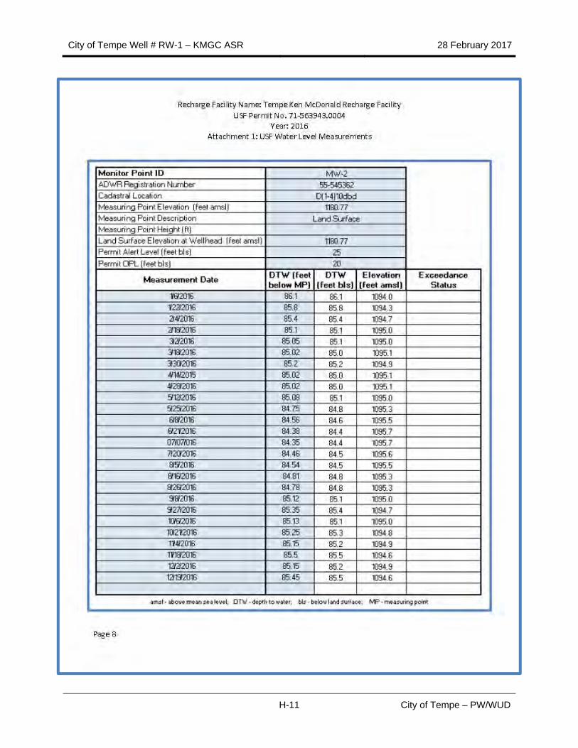
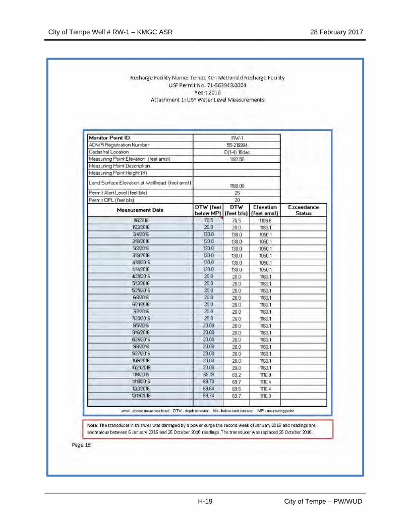
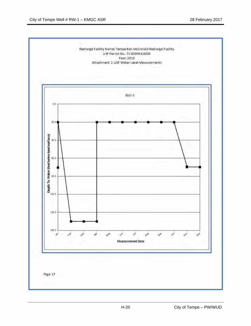
All monitoring wells and RW-1 are monitored for water levels bi-weekly. RW-1 is telemetered through the SCADA system and is polled daily for water levels and performance data. Monitor well MW-2 is also monitored quarterly for water quality purposes to meet permit requirements. The pressure transducer in RW-1 was damaged in January 2016, and replaced in August 2016.
Source: Black and Veatch (2011).
Figure 8 – Monitor Well Locations
1.7 Overall ASR System Performance Summary
The system appears to operate within original design parameters, with the caveat that recharge events have occurred irregularly. Recharge occurred for four months in 2014 following start up in July through November at rates up to 0.735 MGD. 2015 recharge occurred in July and
City of Tempe Well # RW-1 – KMGC ASR 28 February 2017
12 City of Tempe – PW/WUD
August, at a maximum of 1.18 MGD. Recharge did not occur in 2016. Recharge has not approached the design rate of 1.7 MGD.
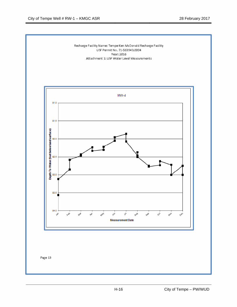
Groundwater elevations have stayed below permitted alert limits, generally between 81 and 86 feet bgs during 2014 and 2015 recharge periods. Significant mounding does not appear to have occurred, and significant changes in groundwater elevations have not been observed in nearby monitoring wells. It also appears that the system has not been stressed enough to evaluate constructed capacity of recharge in RW-1, nor potential long-term effects upon the aquifer.
.
City of Tempe Well # RW-1 – KMGC ASR 28 February 2017
13 City of Tempe – PW/WUD
Table 5 - KMGC ASR RW-1 Summary
Well Location
Address 800 E. Divot Drive Tempe, AZ 85283
Latitude/Longitude 33.353850 ‐111.931778
T/R, Section 1S 4E 10
Surface Elevation 1,180.08 Feet
Maricopa County APN 301‐47‐459D
Legal Description E2 SE4 EX Beg SE Cor Sec TH N 1155.02F TH W 1055.02F TH S 1155.02F TH E
1055.02F TO POB & EX S 55F & E 55F RDS & Ex Any Portion within Tempe
6‐hour step test at 750, 1,000 and 1,300 gpm @ 2 hours/step. SC = 113.7 gpm/ft at 750 gpm was. SC at 1,000 and 1,300 gpm were 102.1 gpm/ft and 90.6 gpm/ft. Injection testing was conducted at 14 psi, flow rate between 410 and 420 gpm.
Active Recharge Water Level
80 – 87 Feet bgs
Initial Recharge Rate 0.7 MGD 1 July 2014
Permitted Recharge Rate 1.7 MGD Per ASR Well
Current Recharge Rate 1.14 MGD 30 August 2015
City of Tempe Well # RW-1 – KMGC ASR 28 February 2017
14 City of Tempe – PW/WUD
Table 5- KMGC ASR RW-1 Summary (Continued)
Well Equipping
V‐Smart Downhole flow control valve.
Pump Intake Depth 150 Feet BGS
Pump System Summary 60 HP submersible electric pump designed to provide intermittent backwashing cycles at up to 1,500 gpm with a VFD and controlled in concersrt with the V‐Smart
flow control valve systems. Discharge it to a small lake on the golf course.
Data Logger ? Yes, recharge flow, backwash cycles and water levels are logged automatically.
Well Repair and Rehabilitation Summary
Repair/Rehab Activity N/A
Rehab Methods Used N/A
Encrustation Unknown
Well Re‐development N/A
Ground Water Quality Summary – Monitor Well MW‐2
TDS 1,115.4 mg/L
pH 7.2 mg/L
Hardness 279.4 mg/L
Alkalinity 340 mg/L
Conductivity 1,518.8 mg/L
Turbidity 0.35 mg/L
VOC’s ND mg/L
SVOC’s ND mg/L
Metals As – 0.0049; Ba – 0.076; Cr – 0.0022; Fe – 0.4;
Mg – 28.8; Se – 0.0013 mg/L
IOC’s ND mg/L
Radionuclides NA mg/L
Microbiology Absent P/A
Anything else of note: Values shown above are averages for the period September 2013 to July 2016
City of Tempe Well # RW-1 – KMGC ASR 28 February 2017
15 City of Tempe – PW/WUD
1.8 Recommendations
ASR well RW-1 was used intermittently through 2014 and 2015, and was not utilized in 2016. The lack of full use has not allowed testing and evaluation of short and long term effects of recharge, and has not allowed for the development of a specific backwash cycle.
It is recommended that COT retain a consultant with ASR expertise to evaluate the system under full recharge conditions, evaluate backwashing protocols, evaluate previous research and studies for performance, well siting, and design parameters. The project should include requirements and permitting for expansion of the current system with two to four new ASR wells to accommodate re-activation of the Kyrene WRF within the next two to five-years.
Table 6 - KMGC ASR RW-1 Action Items
Action Item #
Date Description By (Name)
1 28 February 2017 Retain an engineering/hydrogeologic consultant to evaluate current system parameters, future requirements at
potential build out of Kyrene WRF, permitting needs, etc.
Dean Alford
2
3
4
5
Table 7 - KMGC ASR RW-1 Activity Tracking
Action Item #
Date Description By (Name)
City of Tempe Well # RW-1 – KMGC ASR 28 February 2017
16 City of Tempe – PW/WUD
2.0 WATER QUALITY SUMMARY
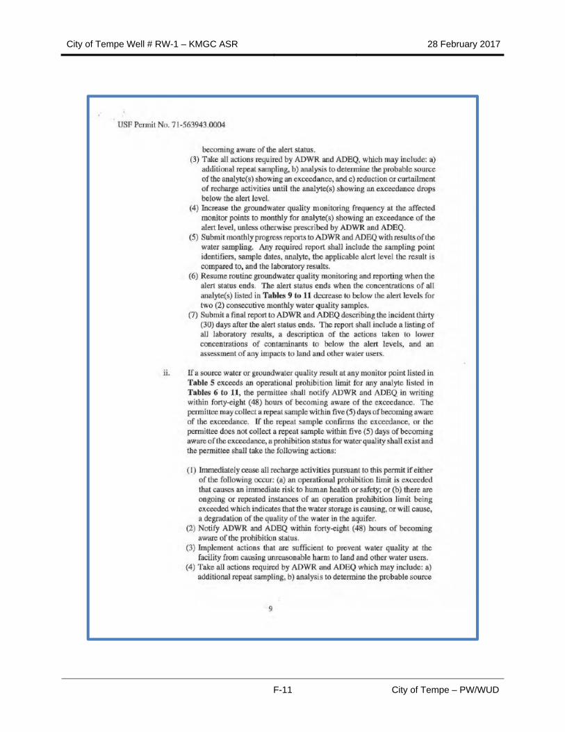
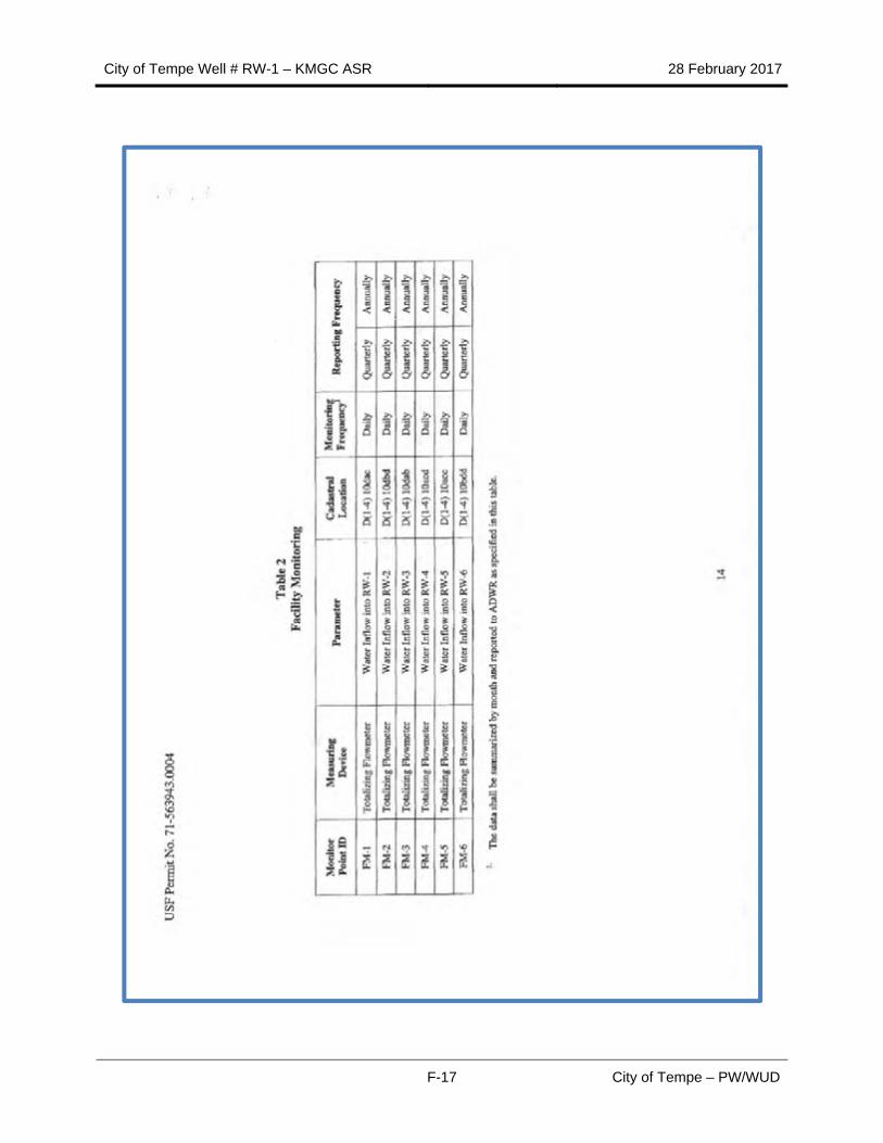
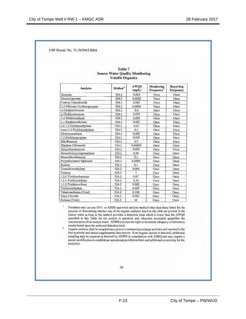
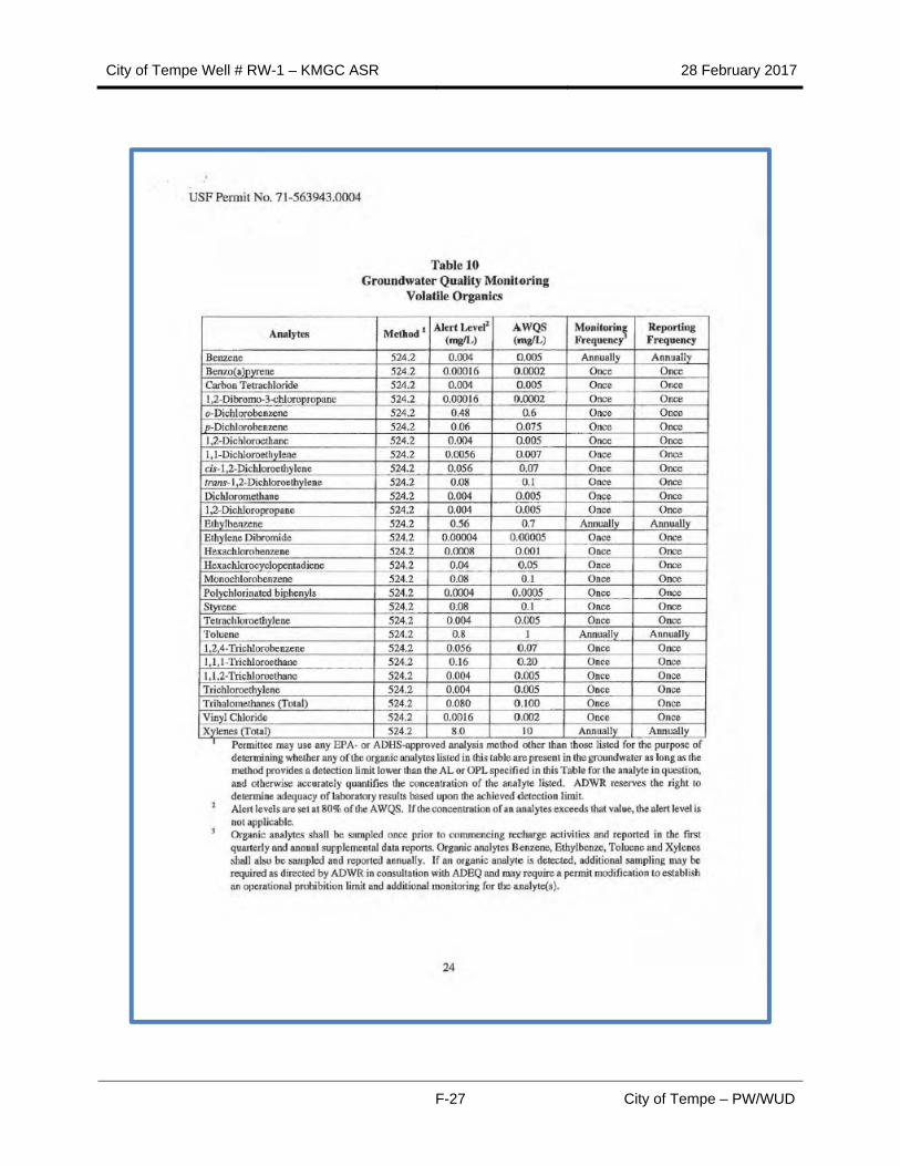
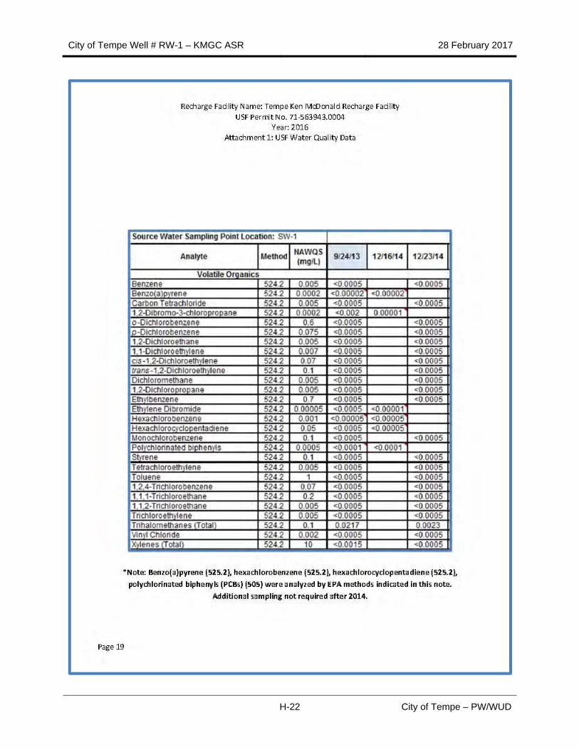
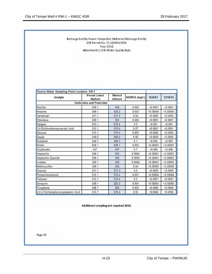
Water supplied for recharge at RW-1 was originally designed to consist of treated effluent from the Kyrene WRF. When the WRF was mothballed, potable water was delivered via a distribution pipeline from the South Tempe Water Treatment Plant (STWTP) to RW-1. Source water quality in for either source is carefully controlled and monitored. To meet permit requirements (under ADWR USF Permit Number 71-563943.0004, Appendix F) and evaluate potential upset conditions, water quality is monitored monthly for source water and in groundwater in Monitoring Well #2. Water quality data has been collected and tabulated quarterly from 24 September 2013 to present. Summary data is presented in Appendix D.
2.1 Groundwater Protection and Potential Contaminant Sources
Two industrial sites are near the KMGC ASR facility, but at this time do not to appear to pose an environmental impact to the facility. The Capitol Castings facility, to the northwest of KMGC, is undergoing active groundwater remediation. SRP’s Kyrene Generating Station (KGS) is to the west and southwest of KMGC and does have any reported releases of potential contaminants to the environment that might impact KMGC ASR operations. Each site is discussed in the following sections.
2.1.1 Capitol Castings Remediation Site
The Capitol Castings foundry facility is northwest of the ASR wells (Figure 8) and encompasses a monitoring well network (Figure 9), and 1,1-DCE affected groundwater (Arcadis, 2016). The facility is located at 5857 South Kyrene Road and is bounded by the Western Canal and Kiwanis Park to the north and east, UPRR to the west, and Guadalupe Road to the south (Figure 1) (Arcadis, 2016).
Operation of the facility began in 1953 as a secondary steel foundry that produced various steel castings used primarily by the mining industry for wear-resistant and structural applications. VTI owned and operated the facility from 1988 until 1994, when the facility was purchased by ME International. ME International’s successor in interest, ME Elecmetal (ME Global), currently owns and operates the site as a metals casting facility.
Groundwater at the site is affected by a chlorinated volatile organic compound (CVOC) release and a gasoline leaking underground storage tank (LUST) release. Based on the historical evaluations, 1,1-DCE, 1,2-dichloroethane (1,2-DCA) and benzene are the primary contaminants of concern COCs. These three compounds are detected above their respective Arizona Aquifer Water Quality Standards (AWQS) and the maximum concentrations are typically two times greater than their respective AWQS, based on previous site investigations. 1,2-DCA and benzene are related to the LUST release and the 1,1-DCE is related to the CVOC release. 1,1-DCE is the only chemical in groundwater present beyond the facility boundary. The LUST is being addressed by a separate plan. Historical information regarding the site, the two releases, and historical remedial actions is available in the ADEQ-approved Final Feasibility Study (FS) Report and the Leaking Underground Storage Tank (LUST) Groundwater Closure Assessment Report (ARCADIS 2014a and 2014b), respectively.
City of Tempe Well # RW-1 – KMGC ASR 28 February 2017
17 City of Tempe – PW/WUD
Groundwater monitoring of the 1,1-DCE affected groundwater has been ongoing since 1993 and the monitoring well network has been expanded to cover the four primary groundwater aquifers (S-, D-, D2-, and D3-Zones). 1,1-DCE has not been detected in the deeper D3b-Zone (lower D3-Zone) or D4-Zone. The horizontal and vertical extent of the 1,1-DCE plume has been heavily influenced by regional pumping in the deeper aquifers. Pumping by Salt River Project (SRP) well 21.5E-1.0S has had the greatest influence on the migration of the plume southerly (ARCADIS 2010). SRP well 21.5E-1.0S is screened in the D2-, A2-, and D3-Zones as well as the unaffected D4-Zone (ARCADIS 2010).
2.1.2 SRP Kyrene Generating Station
SRP owns and operates the Kyrene Generating Station (KGS). The facility consists of one natural gas-fired combined-cycle, two steam and three combustion turbine generator systems (stationary combustion turbines, stationary steam turbines, and heat recovery steam generators); diesel-fired emergency fire water pumps; mechanical draft cooling towers; and associated water supply, water discharge, and natural gas pipelines. The facility generates 521 megawatts from six units; 106 MW from two original steam units, 165 MW from three combustion-turbine units and 250 MW from one combined-cycle unit. The station can burn either natural gas or oil. (ENSR 2001; SRP 2017).
The generating station is located entirely within a 160-acre parcel that includes the generating station and other facilities owned by SRP (Figure 10). Construction began in 1951. Unit 1 was completed July 1, 1952. Unit 2 was completed on June 1, 1954. KGS and supporting infrastructure are shown on Figure 11. Four gas-combustion turbines were built in the early 1970s; one was sold back to the vendor in 1996. The newest unit was completed in October 2002. Unit 4 is a combustion turbine capable of producing power within 20-30 minutes; Units 4 and 6 are 'quick-start' turbines that can produce power in less than 10 minutes to meet peak demands. (SRP 2017).
KGS facility is a small quantity generator of hazardous waste under the Resource, Recovery and Conservation Act (RCRA). Hazardous waste is generated during routine maintenance operations, support operations, and laboratory activities. Wastes generated include small amounts of paints, solvents, and laboratory waste. RCRA wastes are accumulated for no more than 180 days prior to disposal at an approved off-site facility. Solid waste (i.e., office and non-hazardous waste) is disposed of in an off-site sanitary landfill. (ENSR 2001; SRP 2017).
City of Tempe Well # RW-1 – KMGC ASR 28 February 2017
18 City of Tempe – PW/WUD
Source: Arcadis, 2016.
Figure 8 – Capitol Castings Contaminated Site.
City of Tempe Well # RW-1 – KMGC ASR 28 February 2017
19 City of Tempe – PW/WUD
Source: Arcadis, 2016.
Figure 9 – Capitol Castings Facility Contamination Monitoring Well Locations.
City of Tempe Well # RW-1 – KMGC ASR 28 February 2017
20 City of Tempe – PW/WUD
Source: SRP, 2017.
Figure 10 – SRP Kyrene Generating Station.
City of Tempe Well # RW-1 – KMGC ASR 28 February 2017
21 City of Tempe – PW/WUD
Source: SRP, 2017.
Figure 11 – SRP Kyrene Generating Station and Environs.
City of Tempe Well # RW-1 – KMGC ASR 28 February 2017
22 City of Tempe – PW/WUD
BLANK PAGE
City of Tempe Well # RW-1 – KMGC ASR 28 February 2017
23 City of Tempe – PW/WUD
3.0 REFERENCES
Arcadis U.S., Inc. 2016. Victoria Technologies, Inc., Proposed Remedial Action Plan, Former Capitol Castings Site, Tempe, Arizona. VRP Site Code: 504426-00. 29 February 2016.
Arcadis U.S., Inc. 2008. Phase II Groundwater Flow and Solute Transport Model Report Former Capitol Castings Facility, 5857 South Kyrene Road Tempe, Arizona. 6 October 2008.
Arcadis U.S., Inc. 2010. Final Remedial Investigation Report. Former Capitol Castings Facility 5857, South Kyrene Road Tempe, Arizona. 25 October 2010.
Arcadis U.S., Inc. 2014. LUST Groundwater Closure Assessment Report, Former Capitol Castings Facility, Tempe, Arizona, ADEQ VRP Site Code: 504426-00. 30 May 2014.
Arizona Department of Water Resources. 2016. GWSI Well Information. [Online] ADWR, 22 November 2016. [Cited: 22 November 2016.] https://gisweb.azwater.gov/gwsi/SearchGWSI.aspx
ASL Hydrologic and Environmental Services and GeoWest Group, Inc. 1993. Hardy Farms Recharge Facility Feasibility Study Final Report. September 1992.
ASR Resources, LLC. 2016. ASR Valve Operation. [Online] ASR, 29 December 2016. [Cited: 29 December 2016.] http://www.asrresources.com/overview.cfm?where=overview
ASR Resources, LLC. 2013. V-Smart Control Valve Installation, Operation & Maintenance Manual, Ken McDonald Golf Course ASR Well #1. April 2013.
Black and Veatch. 2011. Kyrene WRP and Ken McDonald Golf Course Reclaimed Water Recharge Project. 4 March 2011.
Black and Veatch. 2011. Kyrene WRP and Ken McDonald Golf Course Reclaimed Water Recharge Project. 29 July 2011.
Black and Veatch. 2011. Ken McDonald Golf Course Groundwater Recharge Well No. 1. CIP Project No. 3209301. November 2011.
Black and Veatch. 2012. Ken McDonald Golf Course Groundwater Recharge Well No. 1. CIP Project No. 3209301. January 2012.
Brown & Caldwell. 2001. Well Electrical/Piping and Reclaimed Water Piping Improvements at Ken McDonald Golf Course. October 2001.
Brown & Caldwell. 1999. Recharge at Ken McDonald Golf Course - Phase 1 (1.5 MGD). January, 1999.
Brown & Caldwell. 1999. Technical Specifications for Recharge at Ken McDonald Golf Course - Phase 1. January, 1999.
City of Tempe Well # RW-1 – KMGC ASR 28 February 2017
24 City of Tempe – PW/WUD
Brown & Caldwell. 2001a. Installation of Monitor Wells M-4 and MW-5, Kyrene Water Reclamation Facility Recharge Phase I, Ken McDonald Golf Course, Tempe, Arizona. 13 February 2001.
Brown & Caldwell. 2001b. Technical Specifications for Recharge at Ken McDonald Golf Course - Phase 1 (1.5 MGD). 29 March 2001.
Brown & Caldwell. 2001c. Technical Specifications for Recharge at Ken McDonald Golf Course - Phase 1 (1.5 MGD). 7 June 2001.
Brown & Caldwell. 2001d. Technical Specifications for Recharge at Ken McDonald Golf Course - Phase 1 (1.5 MGD). 25 July 2001.
City of Tempe. 1999. Ken McDonald Golf Course Groundwater Recharge Project Underground Storage Facility Application. 2 March 1999.
City of Tempe. 2001. Well Electrical/Piping and Reclaimed Water Piping Improvements at Ken McDonald Golf Course. October 2001.
City of Tempe. 2010a. Letter and documents from the City of Tempe to the Arizona Department of Water Resources entitled "Underground Storage Permit No. 71-563943." 7 May 2010.
City of Tempe. 2010b. Response to ADWR regarding “Incomplete and Incorrect Determination for Underground Storage Facility Permit No. 71-563943.” 27 September 2010.
City of Tempe. 2012a. Water Service Area - Water Resources Plan, Tempe Public Works Department Water Utilities Division. February 2012.
City of Tempe. 2012b. Letter to ADWR regarding Underground Storage Permit No. 71-563943.0002. 3 August 2012.
City of Tempe, 2012c. Letter to ADWR regarding ”Incomplete & Incorrect Determination for Underground Storage Facility (USF) Application No. 71-563943.0003.” 21 December 2012.
City of Tempe, 2014. Letter to ADWR (with water quality data attachment) regarding ”Ken McDonald Recharge Facility (Permit No. 71-563943.0003).” 29 May 2014.
City of Tempe. 2016a. Water Quality Data. Tempe Public Works Department Water Utilities Division. 2004 - 2016.
City of Tempe. 2016b. Production Water Well Level Data. Tempe Public Works Department Water Utilities Division. 2014 - 2016.
ENSR. 2001. Environmental Assessment, Salt River Project Agricultural Improvement and Power District (SRP), Kyrene Expansion Project, Tempe, Arizona. Prepared for U.S.EPA, Region IX, San Francisco, CA and SRP, Tempe, AZ, January 2001.
City of Tempe Well # RW-1 – KMGC ASR 28 February 2017
25 City of Tempe – PW/WUD
Hydro-Analysis, Inc. 1993. Kyrene Water Reclamation Facility Groundwater Recharge Project – Phase I Final Report, Project #936481. December 1993.
HydroSystems, Inc. 1995. City of Tempe Kyrene Water Reclamation Facility, Ken McDonald Golf Course Groundwater Recharge Project: Hydrologic Report for Underground Storage and Recovery Pilot Project. September 1995.
HydroSystems, Inc. 1997. City of Tempe Ken McDonald Golf Course Groundwater Recharge Project Phase II Report: Groundwater Modeling, Well Installation and Recharge Testing. May 7, 1997.
HydroSystems, Inc. 1998. City of Tempe Ken McDonald Golf Course Groundwater Recharge Facility Numerical Modeling Report. September 1998.
HydroSystems, Inc. 2011. Summary of Drilling and Testing Operations at Recharge Well No. 1, Ken McDonald Golf Course, City of Tempe. March 2011.
Maricopa County Assessor’s Office. 2015. Parcel Viewer. [Online] Maricopa County, 22 November 2016. [Cited: 22 November 2016.] http://maps.mcassessor.maricopa.gov.
Salt River Project. 2017. Kyrene Generating Station. [Online] SRP, 11 January 2017. [Cited: 11 January 2017.] http://www.srpnet.com/about/stations/kyrene.aspx
Wilson and Company. 1991. Reclaimed Water Study for Kiwanis Park and Ken McDonald Lakes, City of Tempe Project No. 896295A. April 1991.
City of Tempe Well # RW-1 – KMGC ASR 28 February 2017
26 City of Tempe – PW/WUD
BLANK PAGE
City of Tempe Well # RW-1 – KMGC ASR 28 February 2017
A-1 City of Tempe – PW/WUD
Appendix A - Well Location Information
City of Tempe Well # RW-1 – KMGC ASR 28 February 2017
A-2 City of Tempe – PW/WUD
BLANK PAGE
City of Tempe Well # RW-1 – KMGC ASR 28 February 2017
A-3 City of Tempe – PW/WUD
Well Location Information
Address 800 E. Divot Drive Tempe, AZ 85283
Latitude/Longitude 33.353850 ‐111.931778
T/R, Section 1S 4E 10 SW¼ NE ¼ SE ¼
Surface Elevation 1,180.08 Feet
Maricopa County APN 301‐47‐459D
Well Location Aerial View
City of Tempe Well # RW-1 – KMGC ASR 28 February 2017
A-4 City of Tempe – PW/WUD
Water Distributions Line to RW‐1
Potable water line begins at the intersection of E. Divot Drive and S. La Rosa Dr.
Valve arrangement for potable supply line to RW‐1.
City of Tempe Well # RW-1 – KMGC ASR 28 February 2017
A-5 City of Tempe – PW/WUD
Well Compound Aerial View
Reclaimed water line on left, potable water line on right, ASR Well in box, control building north of well.
City of Tempe Well # RW-1 – KMGC ASR 28 February 2017
A-6 City of Tempe – PW/WUD
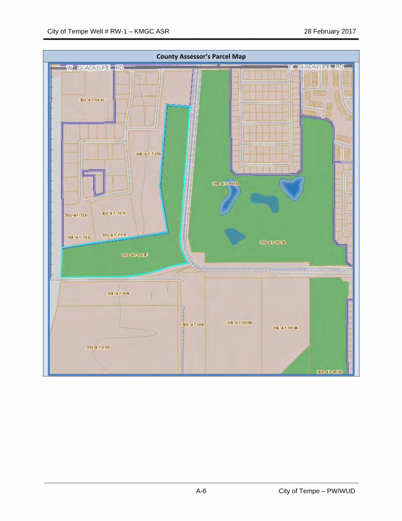
County Assessor’s Parcel Map
City of Tempe Well # RW-1 – KMGC ASR 28 February 2017
B-1 City of Tempe – PW/WUD
Appendix B - Well Drilling and Construction Records
City of Tempe Well # RW-1 – KMGC ASR 28 February 2017
B-2 City of Tempe – PW/WUD
BLANK PAGE
City of Tempe Well # RW-1 – KMGC ASR 28 February 2017
B-3 City of Tempe – PW/WUD
City of Tempe Well # RW-1 – KMGC ASR 28 February 2017
B-4 City of Tempe – PW/WUD
City of Tempe Well # RW-1 – KMGC ASR 28 February 2017
B-5 City of Tempe – PW/WUD
City of Tempe Well # RW-1 – KMGC ASR 28 February 2017
B-6 City of Tempe – PW/WUD
City of Tempe Well # RW-1 – KMGC ASR 28 February 2017
B-7 City of Tempe – PW/WUD
City of Tempe Well # RW-1 – KMGC ASR 28 February 2017
B-8 City of Tempe – PW/WUD
City of Tempe Well # RW-1 – KMGC ASR 28 February 2017
B-9 City of Tempe – PW/WUD
City of Tempe Well # RW-1 – KMGC ASR 28 February 2017
B-10 City of Tempe – PW/WUD
City of Tempe Well # RW-1 – KMGC ASR 28 February 2017
B-11 City of Tempe – PW/WUD
City of Tempe Well # RW-1 – KMGC ASR 28 February 2017
B-12 City of Tempe – PW/WUD
City of Tempe Well # RW-1 – KMGC ASR 28 February 2017
B-13 City of Tempe – PW/WUD
City of Tempe Well # RW-1 – KMGC ASR 28 February 2017
B-14 City of Tempe – PW/WUD
City of Tempe Well # RW-1 – KMGC ASR 28 February 2017
B-15 City of Tempe – PW/WUD
City of Tempe Well # RW-1 – KMGC ASR 28 February 2017
B-16 City of Tempe – PW/WUD
City of Tempe Well # RW-1 – KMGC ASR 28 February 2017
B-17 City of Tempe – PW/WUD
City of Tempe Well # RW-1 – KMGC ASR 28 February 2017
B-18 City of Tempe – PW/WUD
City of Tempe Well # RW-1 – KMGC ASR 28 February 2017
B-19 City of Tempe – PW/WUD
City of Tempe Well # RW-1 – KMGC ASR 28 February 2017
B-20 City of Tempe – PW/WUD
City of Tempe Well # RW-1 – KMGC ASR 28 February 2017
B-21 City of Tempe – PW/WUD
City of Tempe Well # RW-1 – KMGC ASR 28 February 2017
B-22 City of Tempe – PW/WUD
City of Tempe Well # RW-1 – KMGC ASR 28 February 2017
B-23 City of Tempe – PW/WUD
City of Tempe Well # RW-1 – KMGC ASR 28 February 2017
B-24 City of Tempe – PW/WUD
City of Tempe Well # RW-1 – KMGC ASR 28 February 2017
B-25 City of Tempe – PW/WUD
City of Tempe Well # RW-1 – KMGC ASR 28 February 2017
B-26 City of Tempe – PW/WUD
City of Tempe Well # RW-1 – KMGC ASR 28 February 2017
B-27 City of Tempe – PW/WUD
City of Tempe Well # RW-1 – KMGC ASR 28 February 2017
B-28 City of Tempe – PW/WUD
City of Tempe Well # RW-1 – KMGC ASR 28 February 2017
B-29 City of Tempe – PW/WUD
City of Tempe Well # RW-1 – KMGC ASR 28 February 2017
B-30 City of Tempe – PW/WUD
City of Tempe Well # RW-1 – KMGC ASR 28 February 2017
B-31 City of Tempe – PW/WUD
City of Tempe Well # RW-1 – KMGC ASR 28 February 2017
B-32 City of Tempe – PW/WUD
City of Tempe Well # RW-1 – KMGC ASR 28 February 2017
B-33 City of Tempe – PW/WUD
City of Tempe Well # RW-1 – KMGC ASR 28 February 2017
B-34 City of Tempe – PW/WUD
City of Tempe Well # RW-1 – KMGC ASR 28 February 2017
B-35 City of Tempe – PW/WUD
City of Tempe Well # RW-1 – KMGC ASR 28 February 2017
B-36 City of Tempe – PW/WUD
City of Tempe Well # RW-1 – KMGC ASR 28 February 2017
B-37 City of Tempe – PW/WUD
City of Tempe Well # RW-1 – KMGC ASR 28 February 2017
B-38 City of Tempe – PW/WUD
City of Tempe Well # RW-1 – KMGC ASR 28 February 2017
B-39 City of Tempe – PW/WUD
City of Tempe Well # RW-1 – KMGC ASR 28 February 2017
B-40 City of Tempe – PW/WUD
City of Tempe Well # RW-1 – KMGC ASR 28 February 2017
B-41 City of Tempe – PW/WUD
City of Tempe Well # RW-1 – KMGC ASR 28 February 2017
B-42 City of Tempe – PW/WUD
BLANK PAGE
City of Tempe Well # RW-1 – KMGC ASR 28 February 2017
C-1 City of Tempe – PW/WUD
Appendix C - Well and Aquifer Testing Records
City of Tempe Well # RW-1 – KMGC ASR 28 February 2017
C-2 City of Tempe – PW/WUD
BLANK PAGE
City of Tempe Well # RW-1 – KMGC ASR 28 February 2017
C-3 City of Tempe – PW/WUD
City of Tempe Well # RW-1 – KMGC ASR 28 February 2017
C-4 City of Tempe – PW/WUD
City of Tempe Well # RW-1 – KMGC ASR 28 February 2017
C-5 City of Tempe – PW/WUD
City of Tempe Well # RW-1 – KMGC ASR 28 February 2017
C-6 City of Tempe – PW/WUD
City of Tempe Well # RW-1 – KMGC ASR 28 February 2017
C-7 City of Tempe – PW/WUD
City of Tempe Well # RW-1 – KMGC ASR 28 February 2017
C-8 City of Tempe – PW/WUD
City of Tempe Well # RW-1 – KMGC ASR 28 February 2017
C-9 City of Tempe – PW/WUD
City of Tempe Well # RW-1 – KMGC ASR 28 February 2017
C-10 City of Tempe – PW/WUD
BLANK PAGE
City of Tempe Well # RW-1 – KMGC ASR 28 February 2017
D-1 City of Tempe – PW/WUD
Appendix D - Water Quality Records
City of Tempe Well # RW-1 – KMGC ASR 28 February 2017
D-2 City of Tempe – PW/WUD
BLANK PAGE
City of Tempe Well # RW-1 – KMGC ASR 28 February 2017
D-3 City of Tempe – PW/WUD
Water Quality Data Summary - USF Permit No. 71-563943.0004
Sampling Point Location: SW‐1 MW‐2
Analyte OPL (mg/L) Average Average
Field
pH NA 7.59 7.2
Conductivity NA 1111.6 1518.8
Temperature NA 23.0 24.9
Dissolved Oxygen NA 6.7 6.5
Turbidity (NTU) 1 0.5 0.3
Inorganic Analytes
Alkalinity NA 172.2 340
Alkalinity, Bicarbonate NA NA 310
Alkalinity, Carbonate NA NA <10
Ammonia NA <0.082 NA
Boron NA 0.174 0.52
Calcium NA 56.1 62.3
Chloride NA 295.6 346.9
Fluoride 4 0.5 0.4
Hardness (Total) NA NA 279.4
Nitrate (as N) 10 1.89 7.90
Nitrite (as N) 1 <0.10 0.37
Nitrate and Nitrite (as N) 10 1.89 7.9
Potassium NA 5.1 NA
Sodium NA 187.9 312.9
Sulfate NA 83.2 108.8
Total Dissolved Solids NA 758.9 1115.4
Trace Metals
Antimony 0.006 <0.003 <0.003
Arsenic 0.05 0.00219 0.00486
Barium 2 0.065 0.076
Beryllium 0.004 <0.001 <0.001
Cadmium 0.005 <0.001 <0.001
Chromium 0.1 0.00261 0.00219
Copper NA 0.00854 <0.005
Iron NA <0.05 0.4
Lead 0.05 <0.001 <0.001
Magnesium NA 24.1 28.8
Manganese NA 0.001 <0.001
Mercury 0.002 <0.0002 <0.00020
Nickel 0.1 <0.005 <0.0050
Selenium 0.05 <0.001 0.0013
Thallium 0.002 <0.001 <0.001
Zinc NA <0.02 <0.020
City of Tempe Well # RW-1 – KMGC ASR 28 February 2017