COTES C35E/C35D OPERATING AND SERVICE HANDBOOK page 1/101 COTES ALL ROUND C35E-C35D How to install, set up, operate and service your Cotes C35E/C35D dehumidifier Cotes dehumidifier C35E – C35D Manual number: 140712 Revision: B
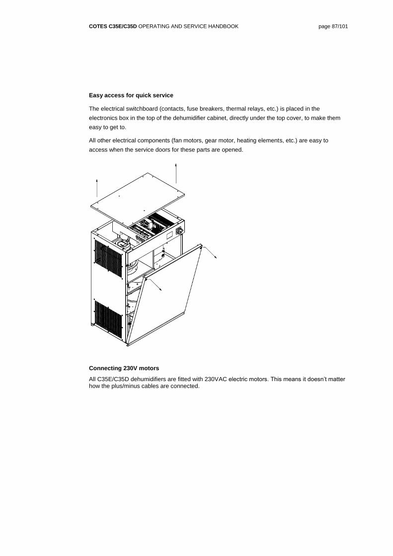
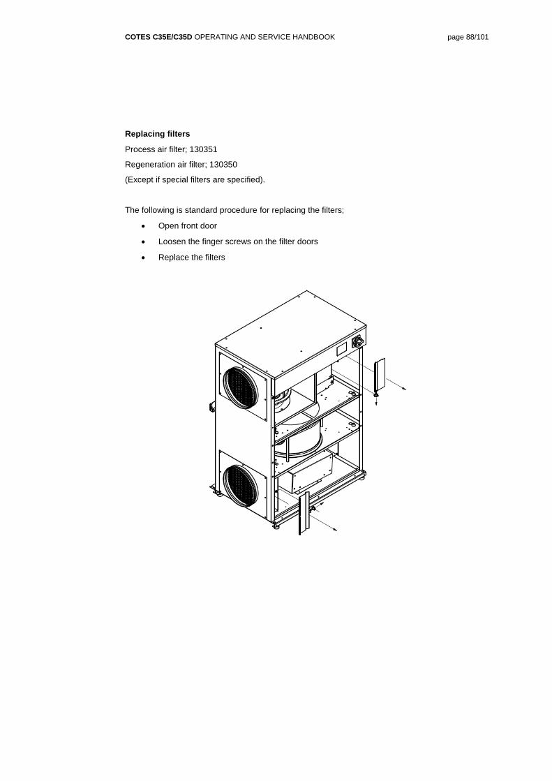
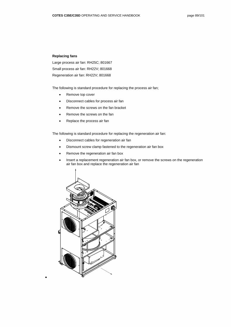
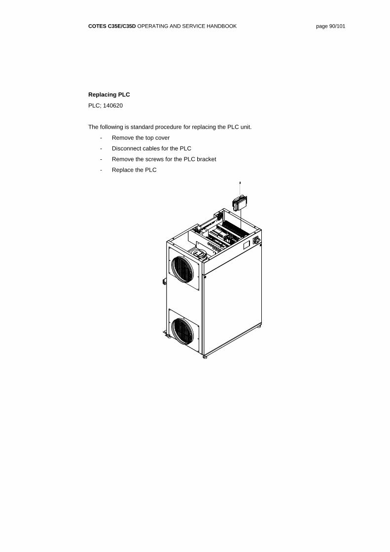
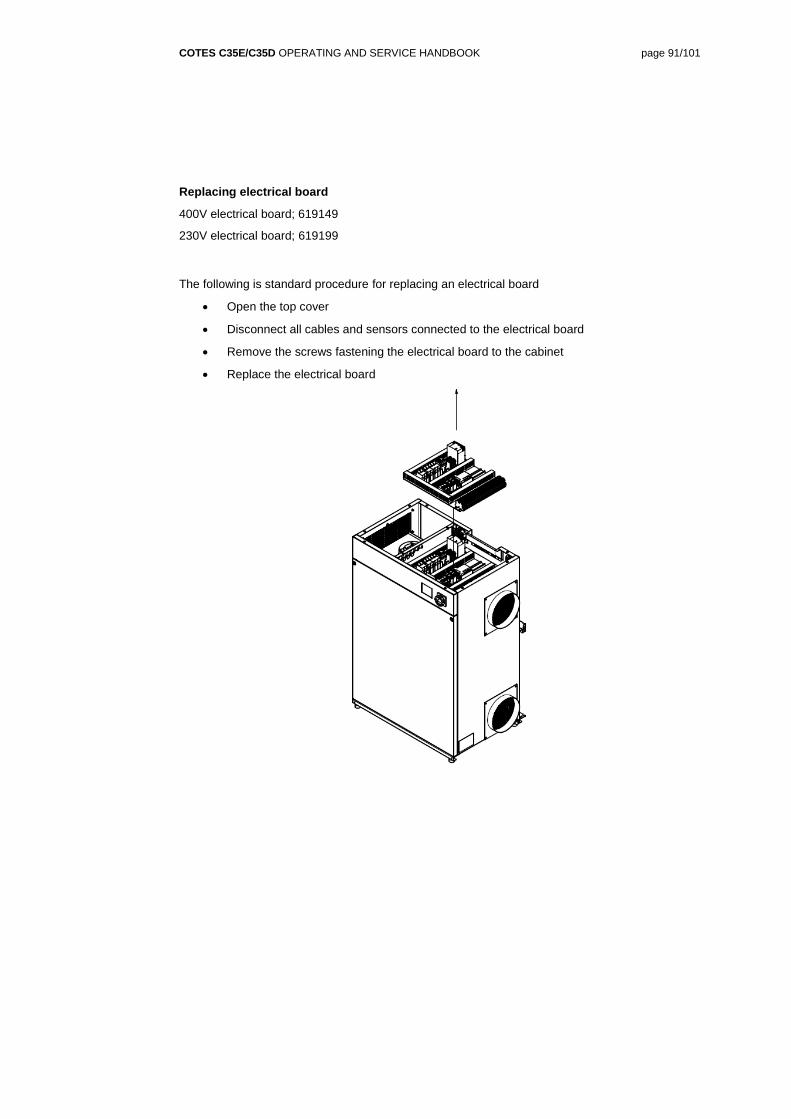
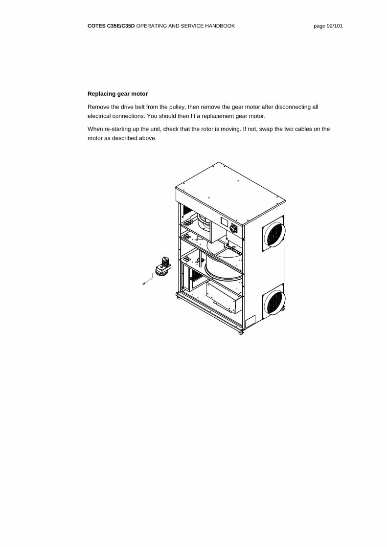
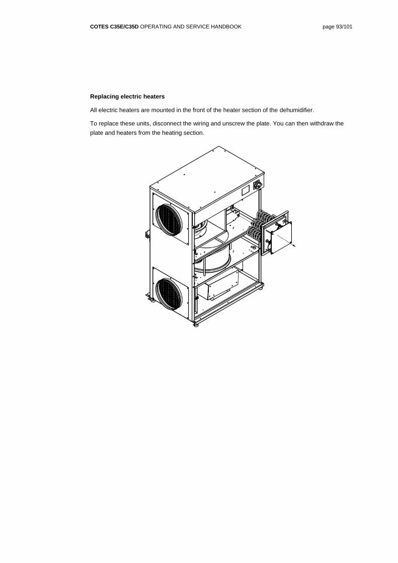
Transcript
COTES C35E/C35D OPERATING AND SERVICE HANDBOOK page 1/101
COTES ALL ROUND C35E-C35D
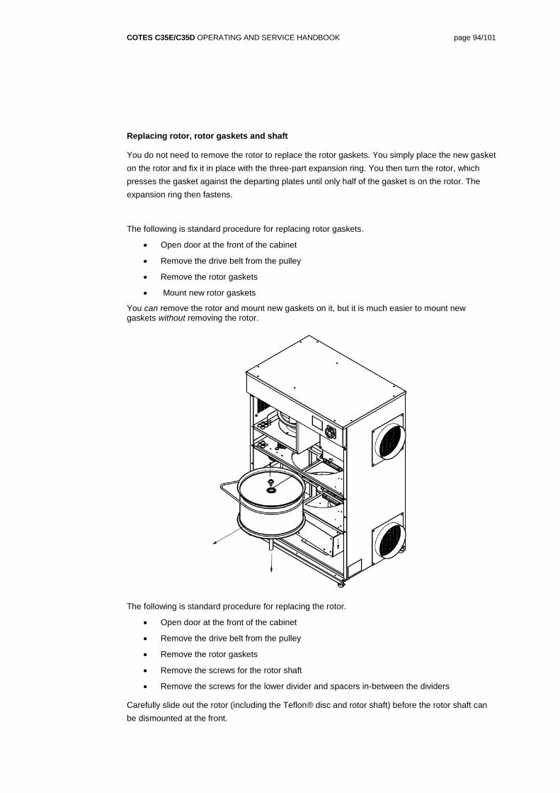
How to install, set up, operate and service your
Cotes C35E/C35D dehumidifier
Cotes dehumidifier C35E – C35D
Manual number: 140712
Revision: B
COTES.COM
CONTENTS
SECTION 1 / GENERAL BACKGROUND 3
ABOUT THIS HANDBOOK 3
ABOUT MANAGING HUMIDITY 5
ABOUT COTES 6
SECTION 2 / THE DEHUMIDIFIER 7
ABOUT THE COTES C35E/C35D RANGE OF DEHUMIDIFIERS 7
HOW IT WORKS 10
FEATURES AND BENEFITS 14
SECTION 3 / TECHNICAL DETAILS 16
SERIAL NUMBER/IDENTIFICATION 16
SPECIFICATIONS 17
ASSEMBLIES AND COMPONENTS 23
SOUND LEVELS 27
SECTION 4 / INSTALLATION 28
HOW TO INSTALL THIS DEHUMIDIFIER 28
HOW TO COMMISSION THIS DEHUMIDIFIER 32
SECTION 5 / OPERATION 34
HOW TO OPERATE THIS DEHUMIDIFIER 34
SECTION 6 / SERVICE AND REPAIR 85
HOW TO SERVICE AND REPAIR THIS DEHUMIDIFIER 85
SECTION 7 / FORMALITIES AND GENERAL/LEGAL INFO 96
WARRANTIES 96
LEGAL NOTICES 97
EU DECLARATION OF CONFORMITY 98
HOW TO UPDATE AND IMPROVE THIS COTES DEHUMIDIFIER 100
WHO TO CONTACT 101
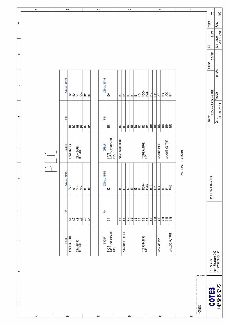
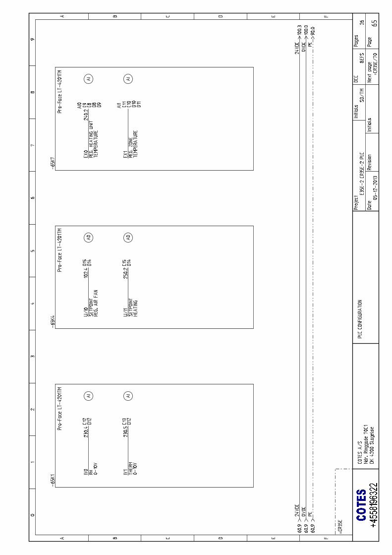
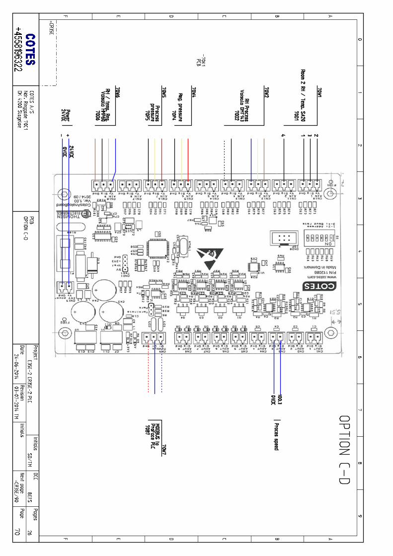
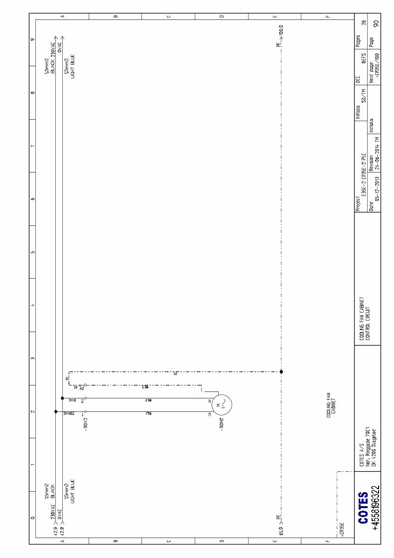
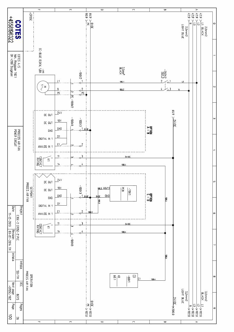
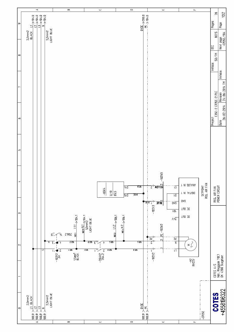
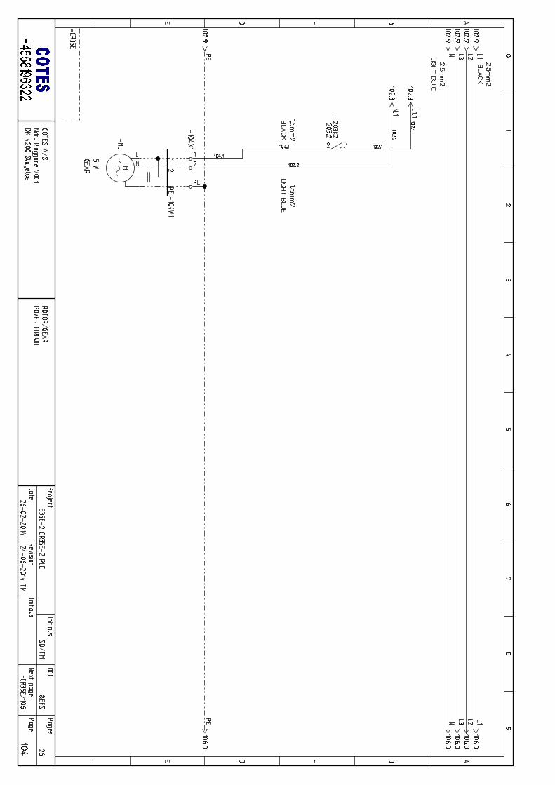
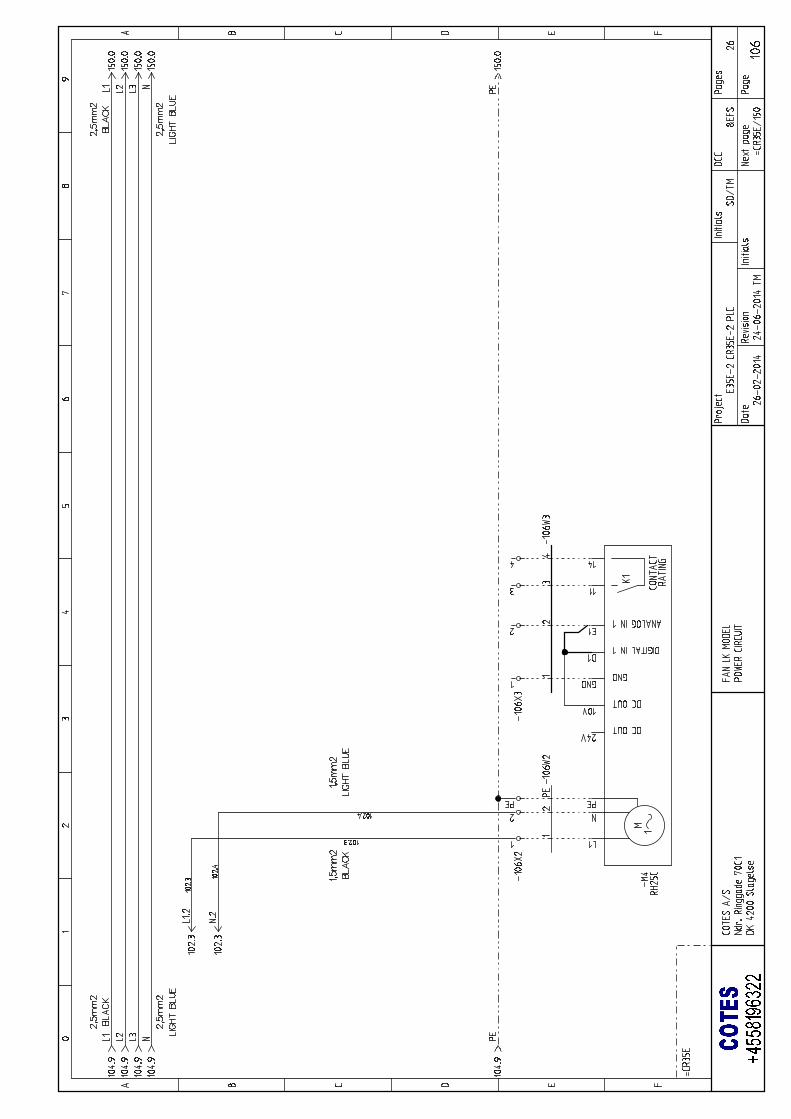
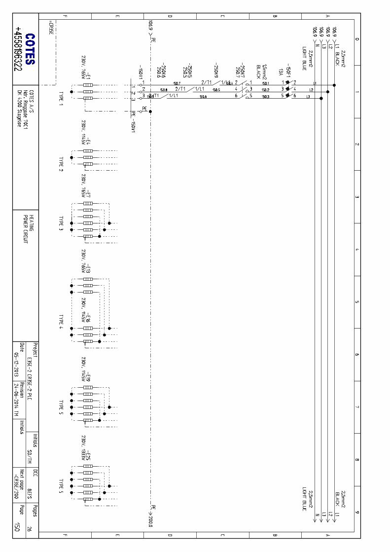
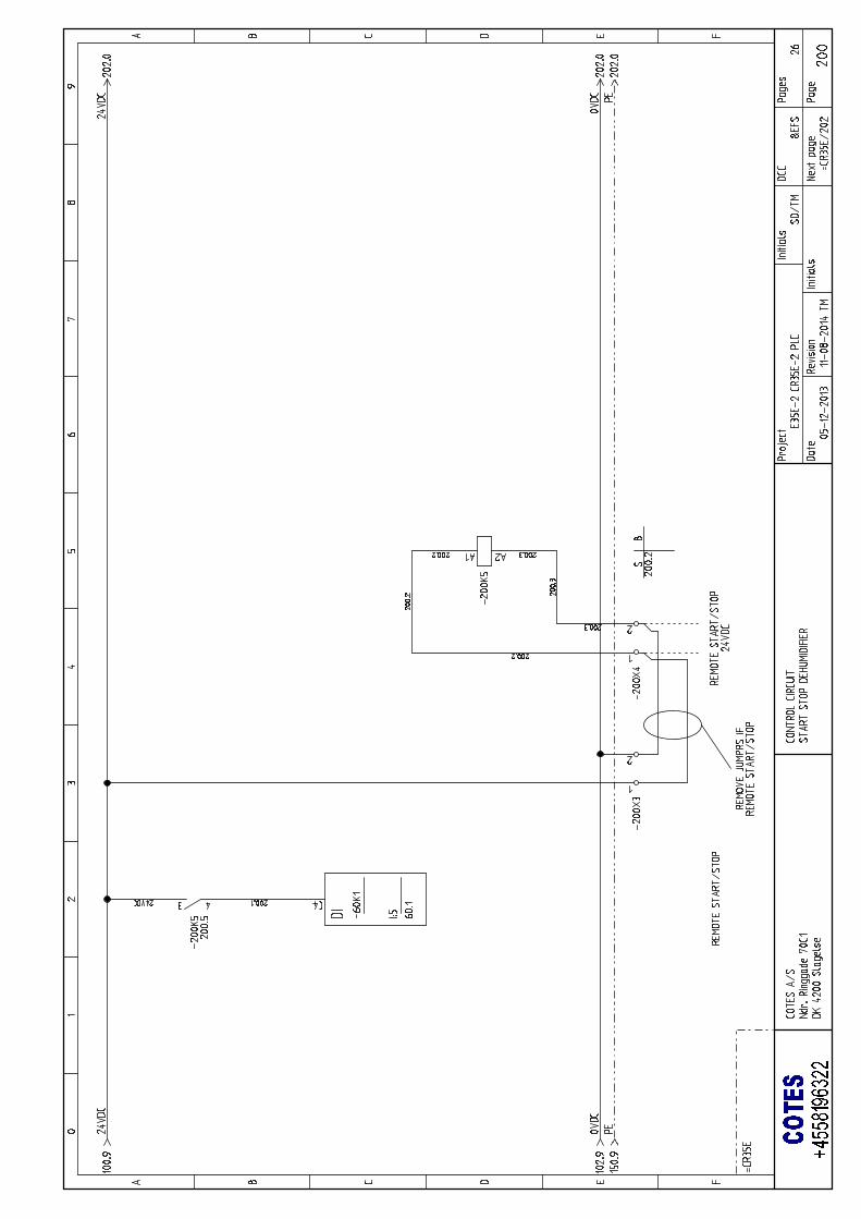
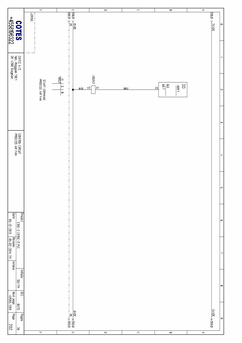
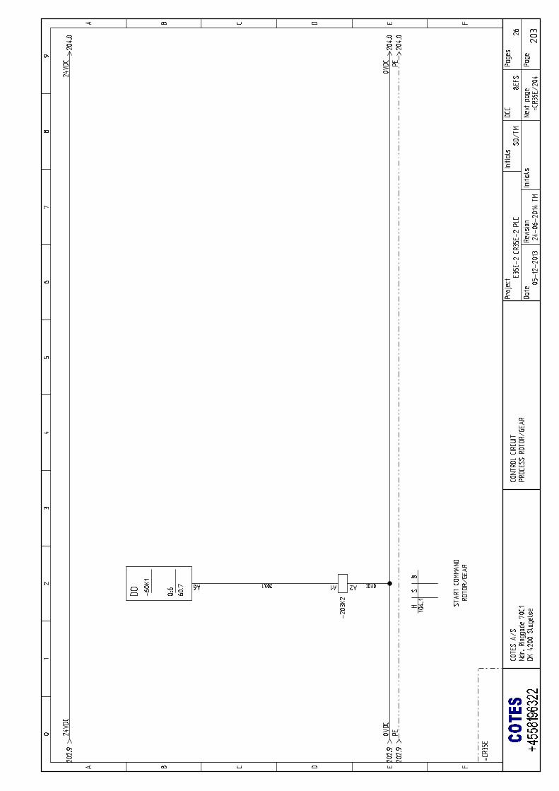
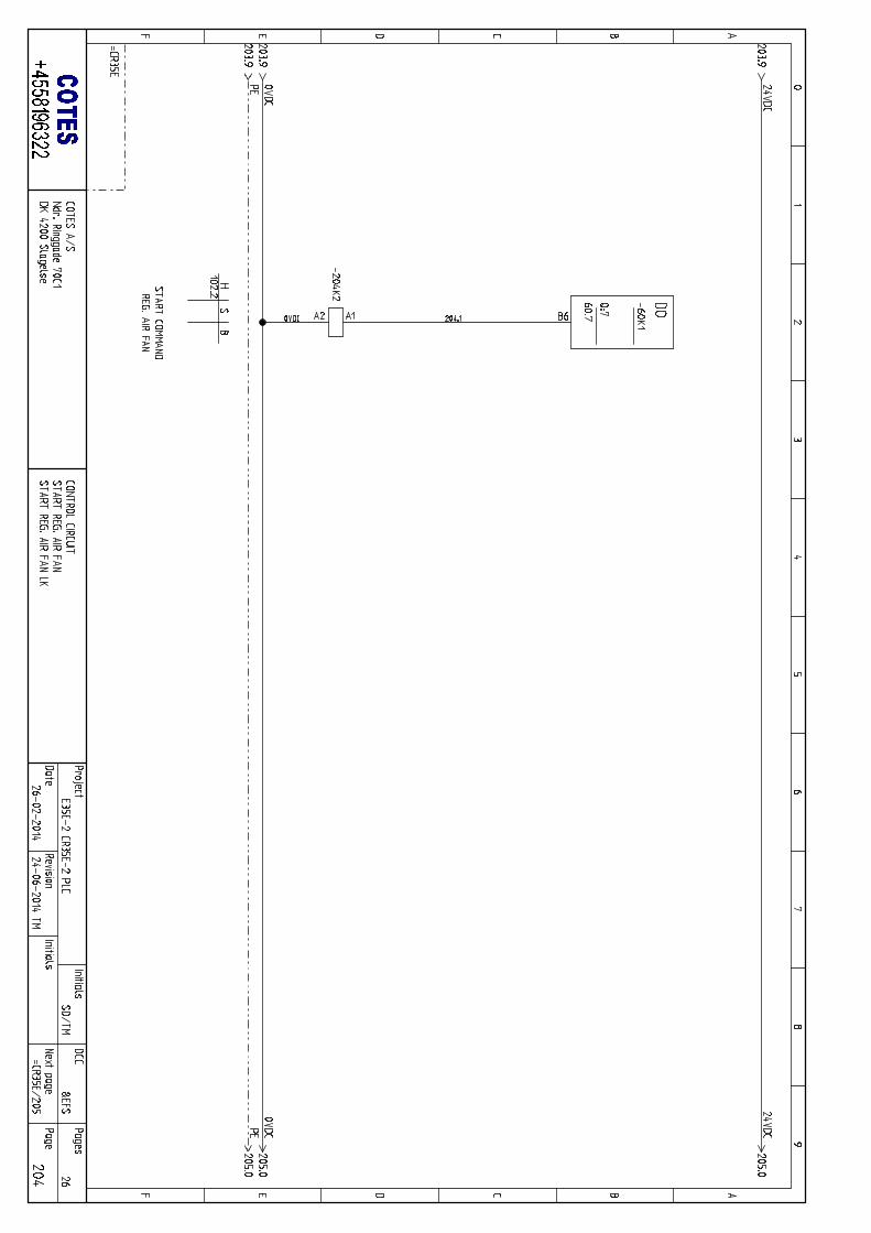
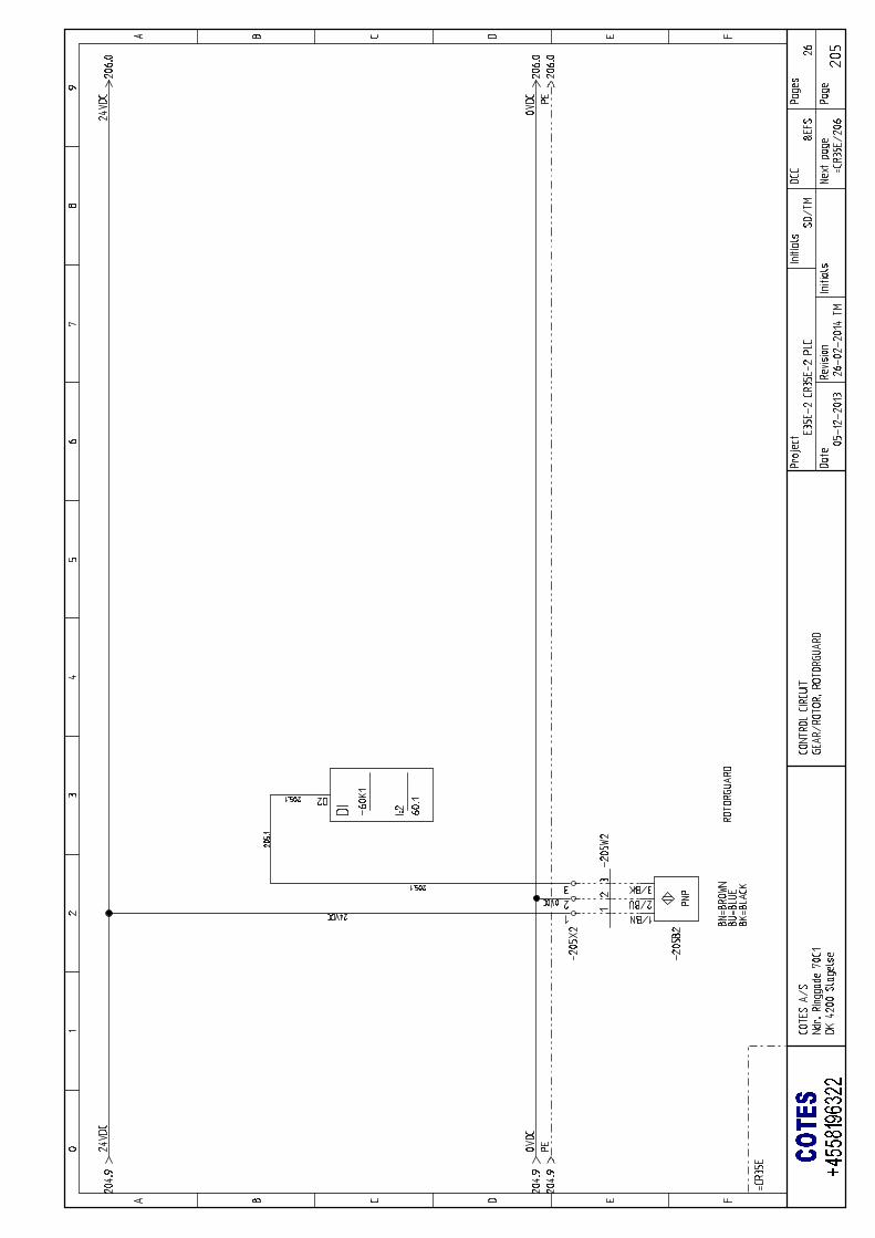
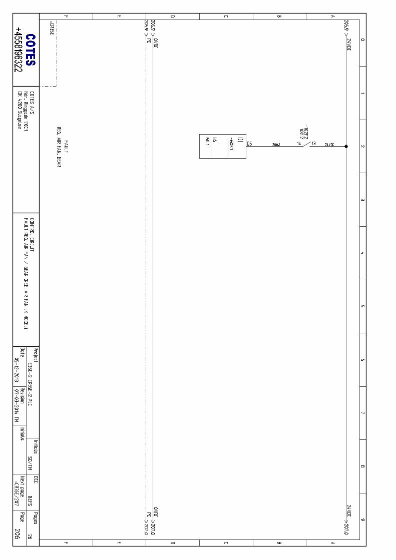
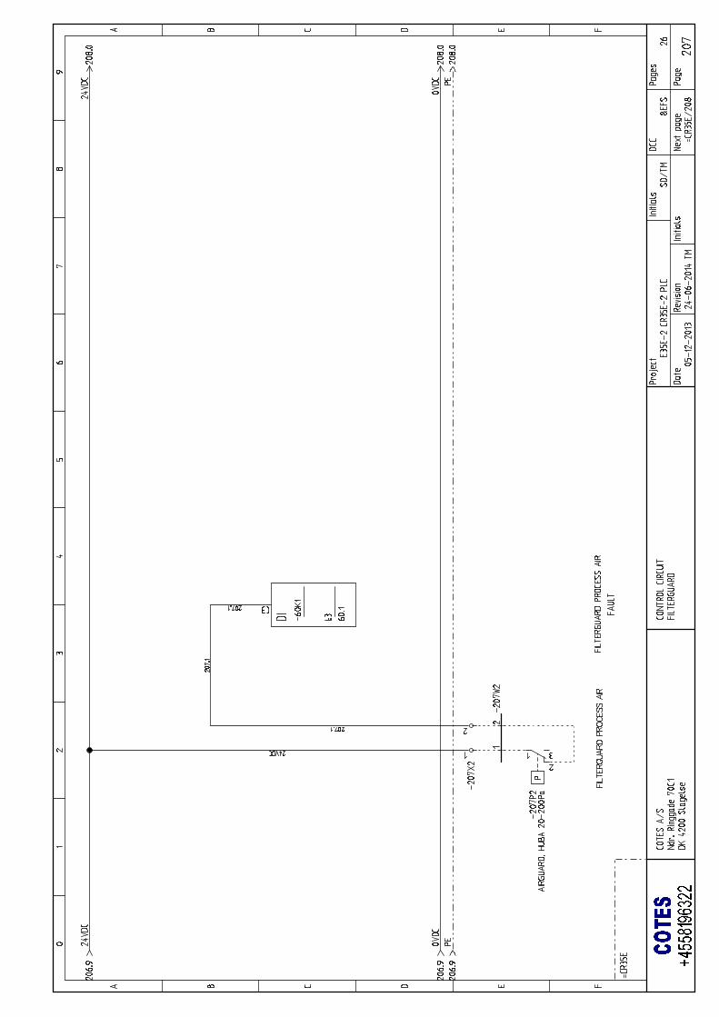
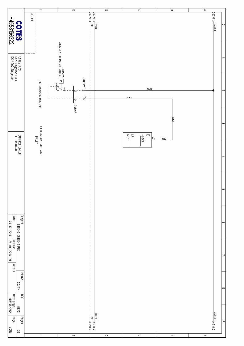
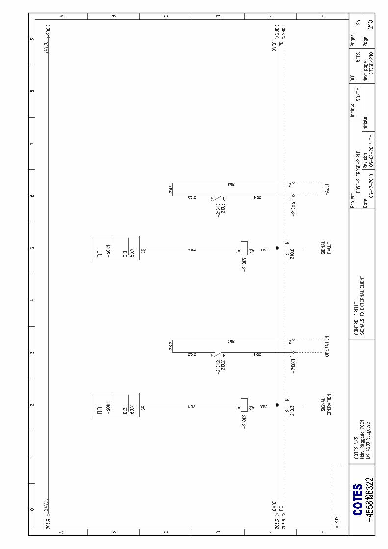
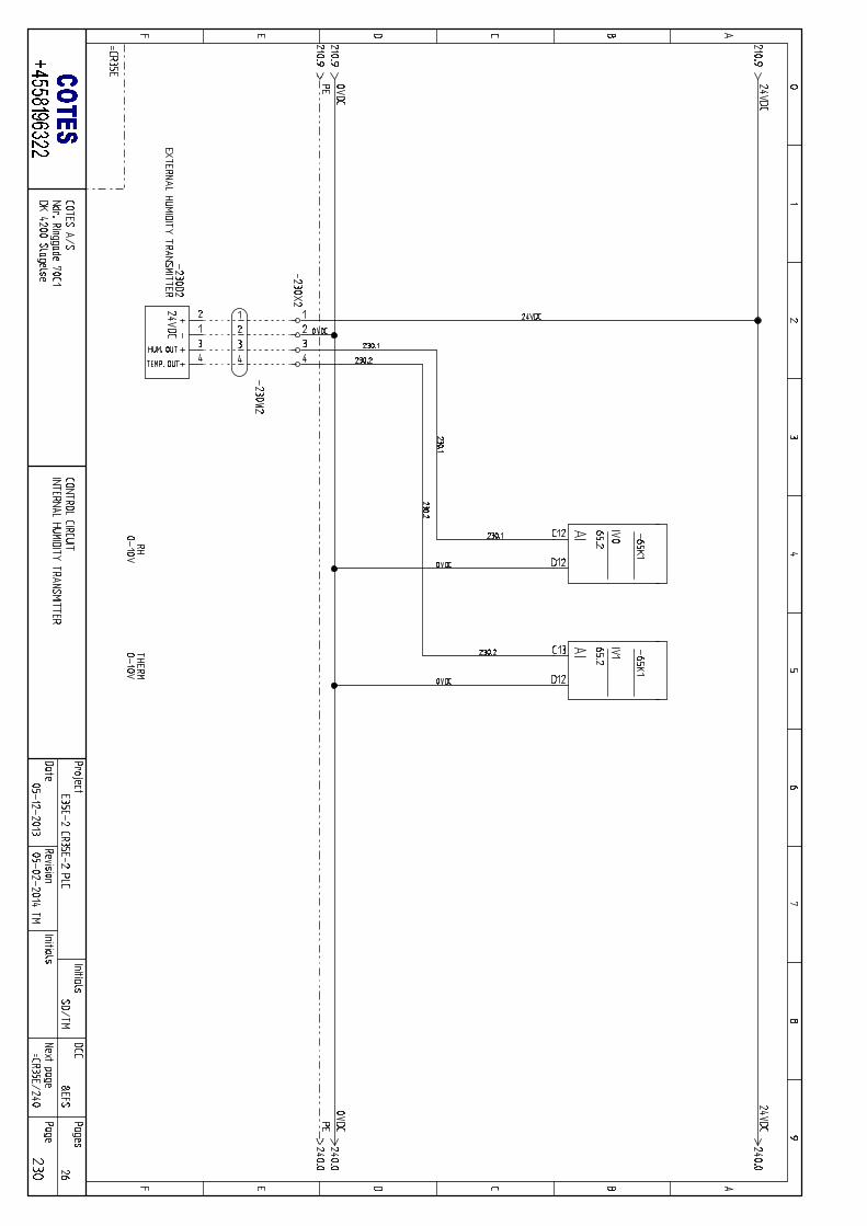
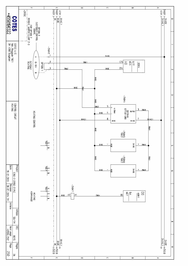
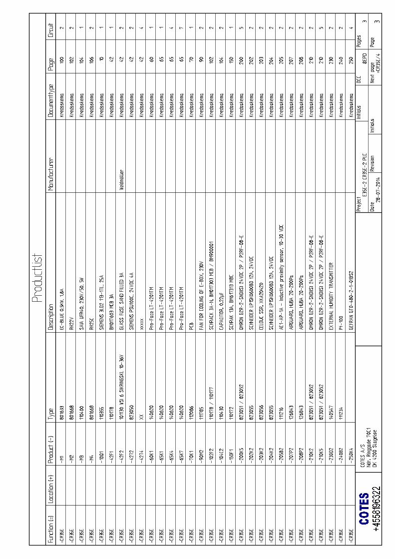
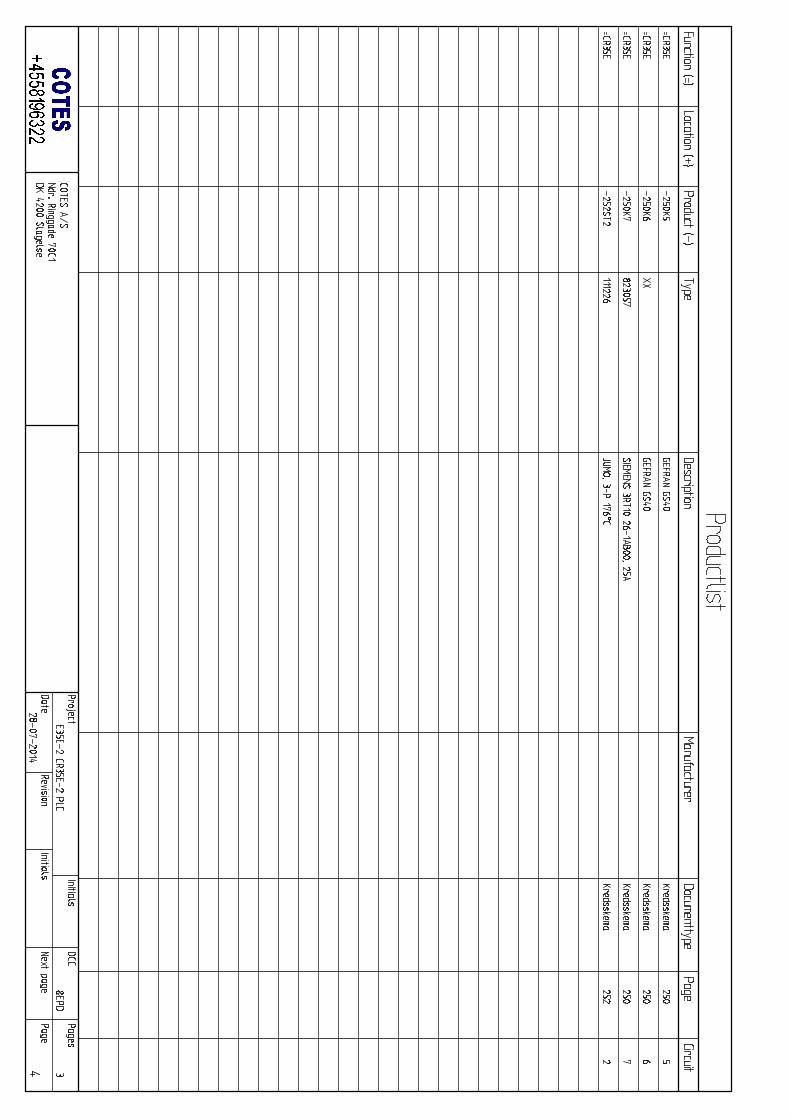
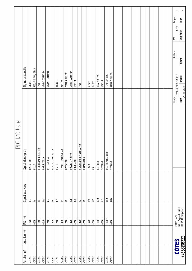
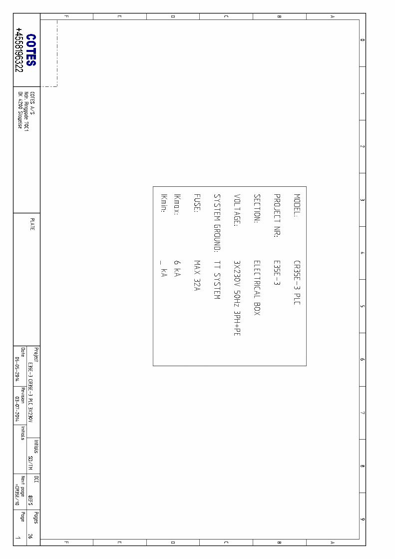
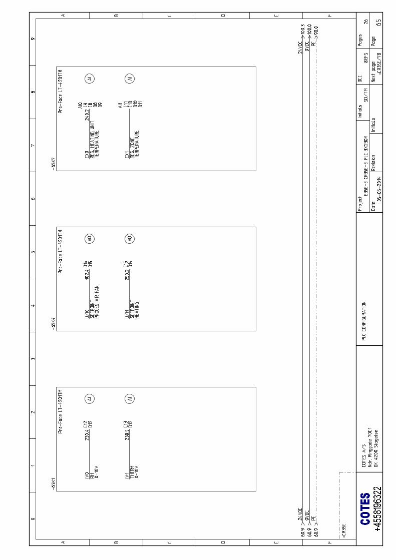
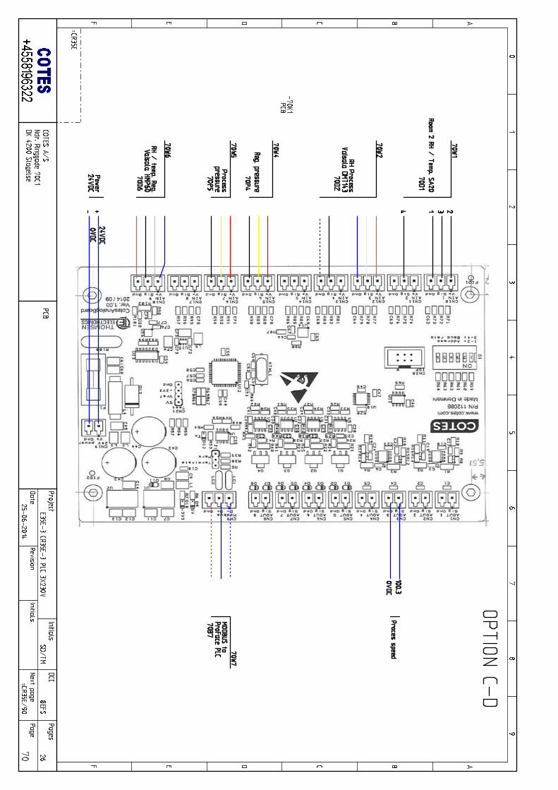
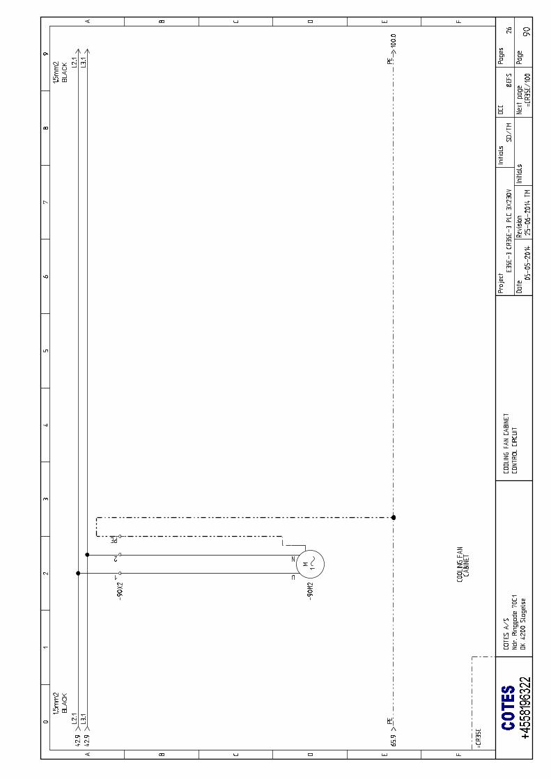
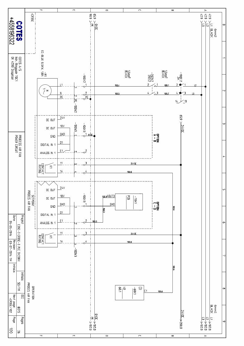
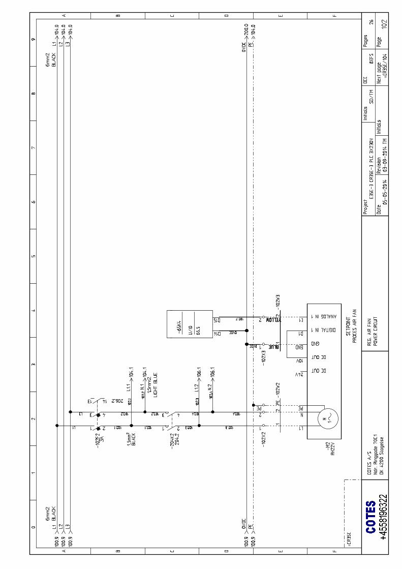
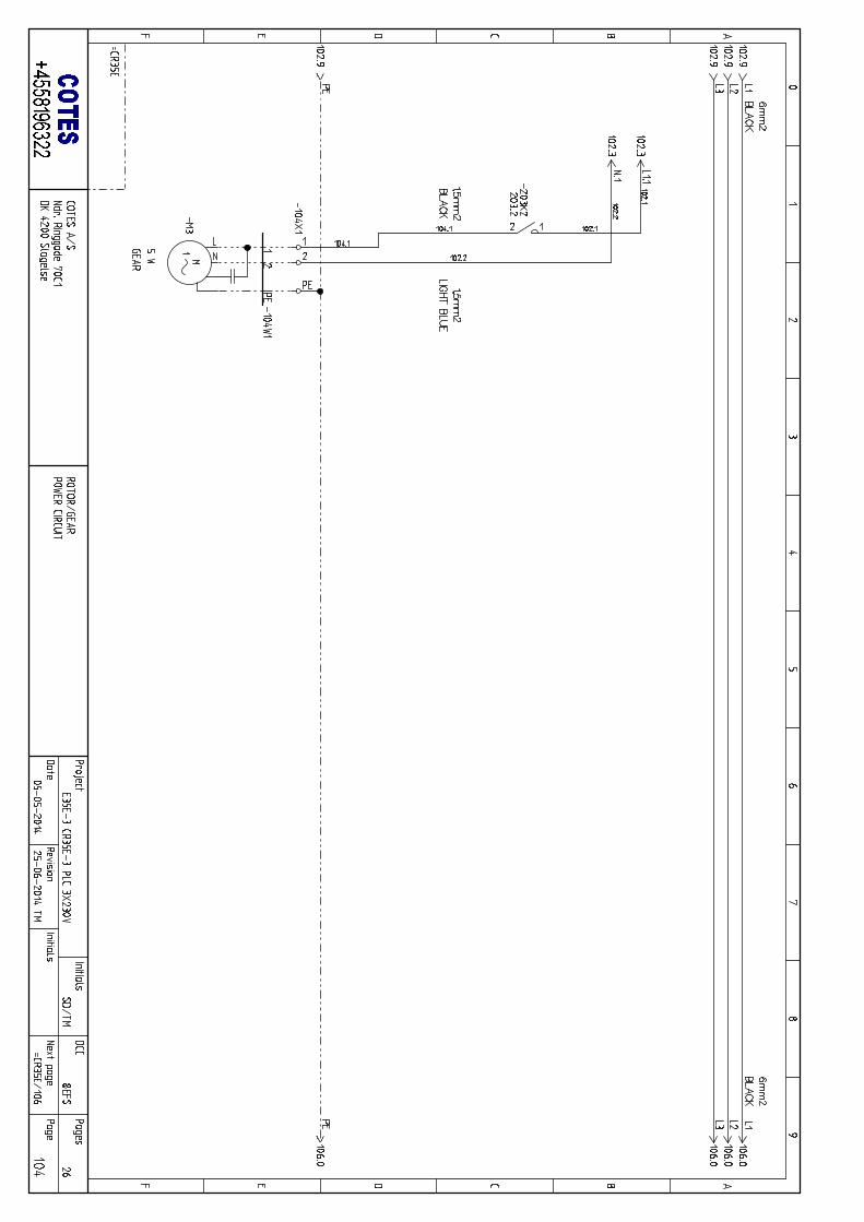
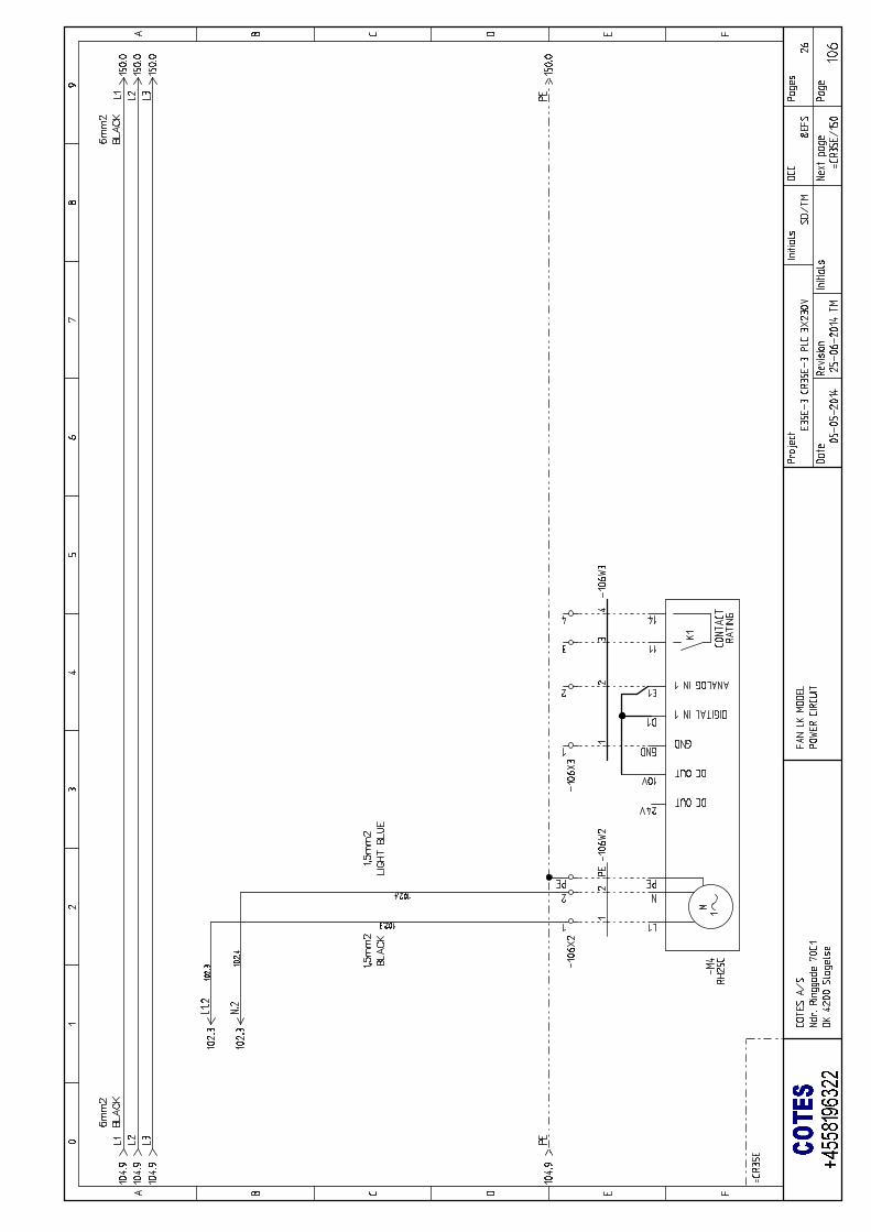
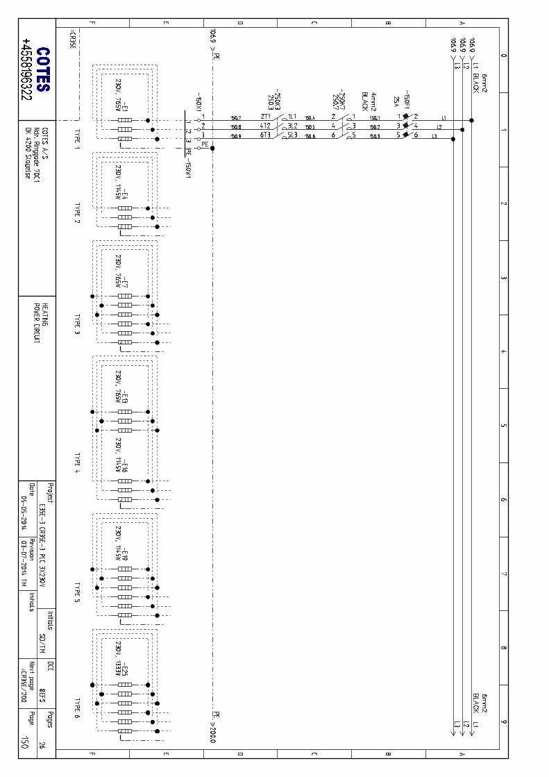
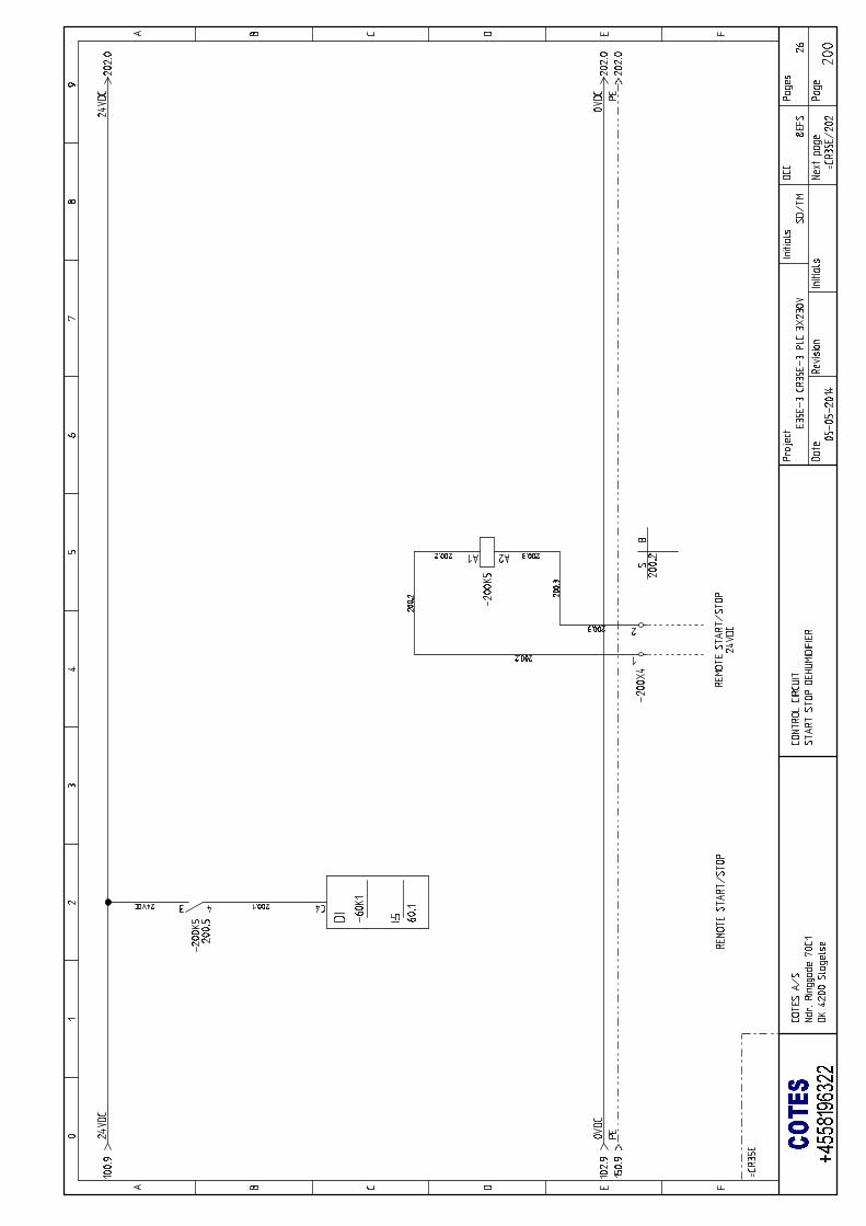
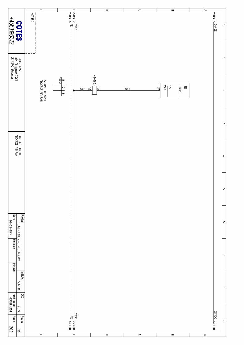
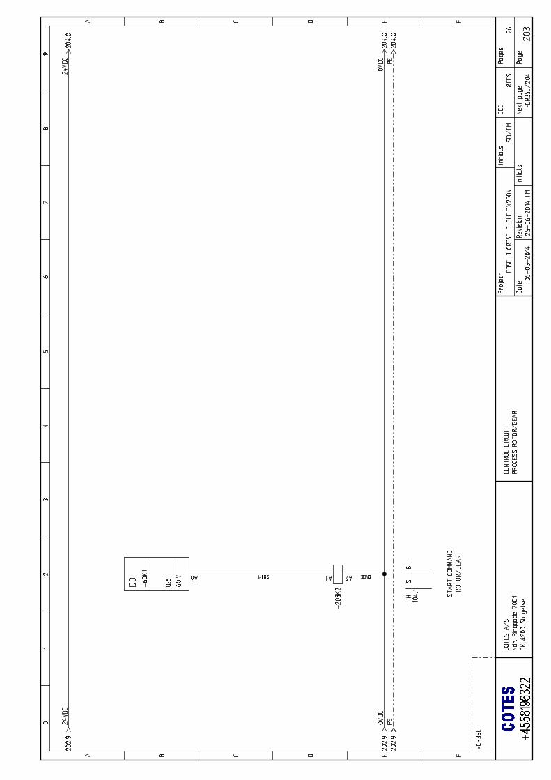
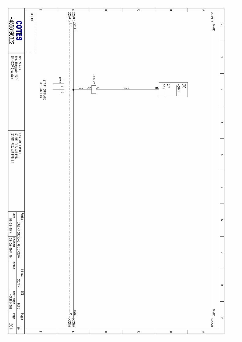
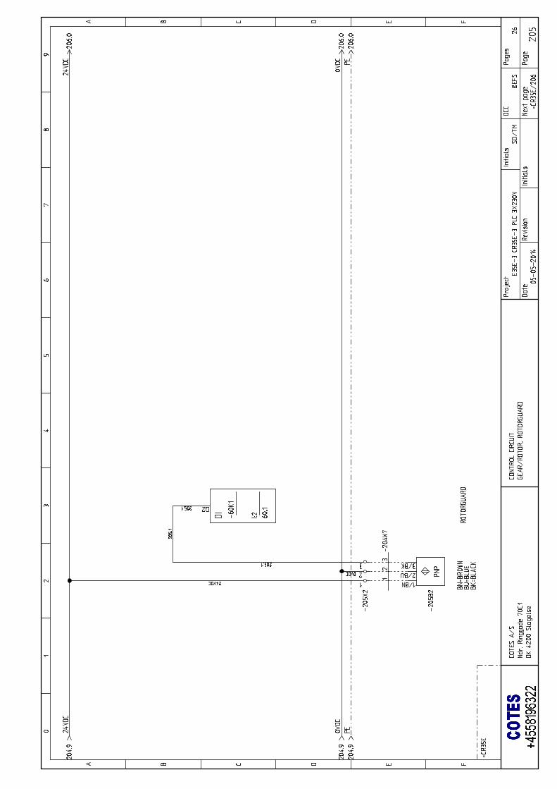
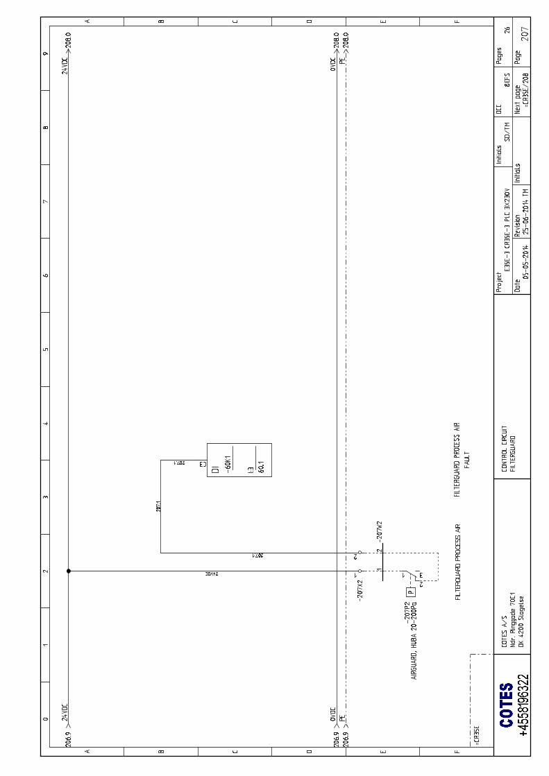
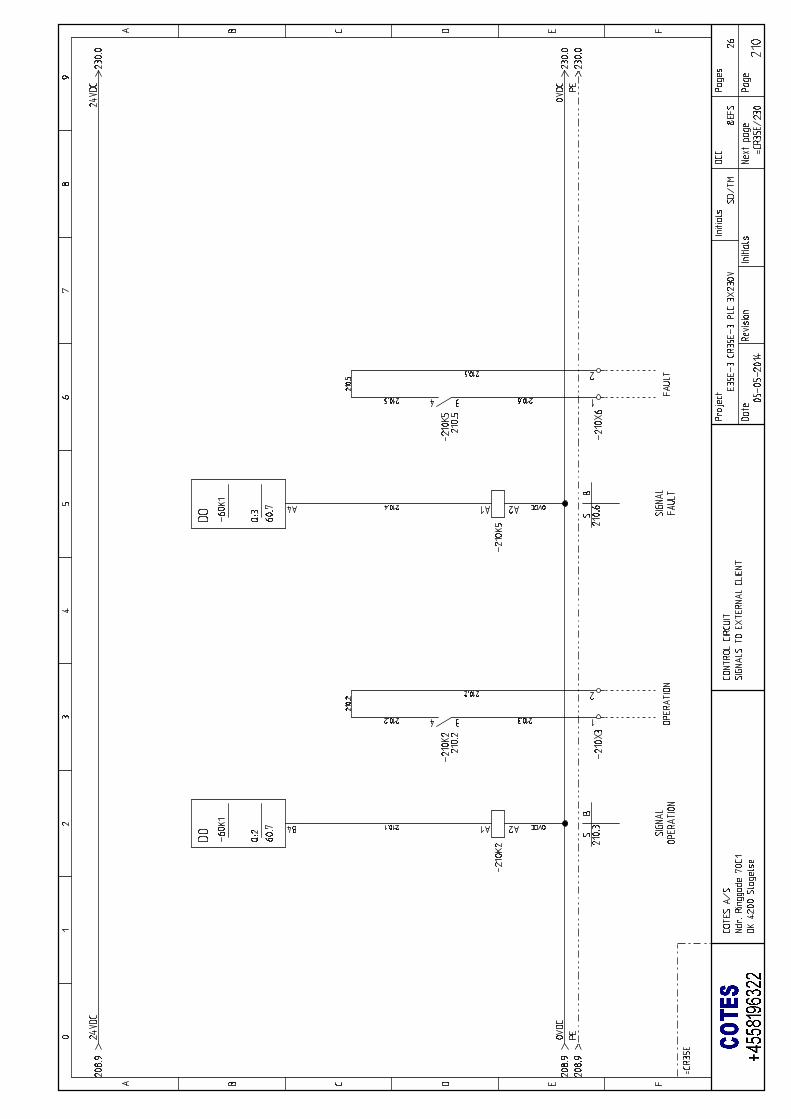
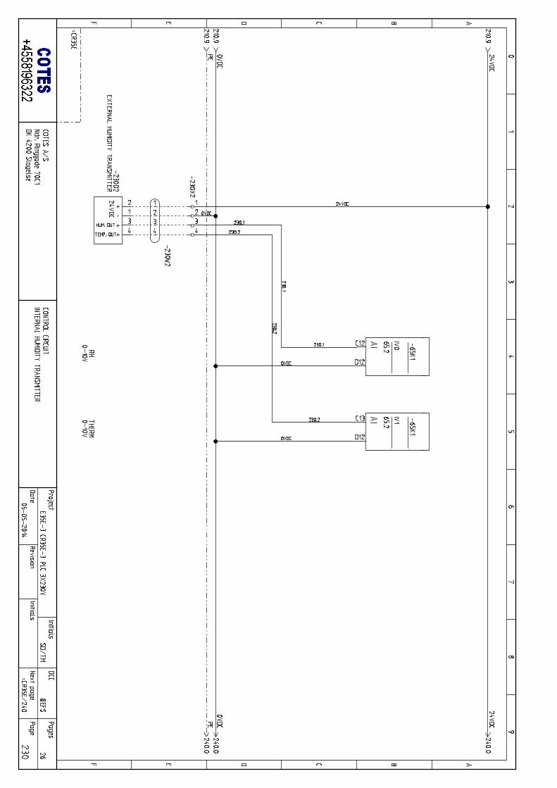
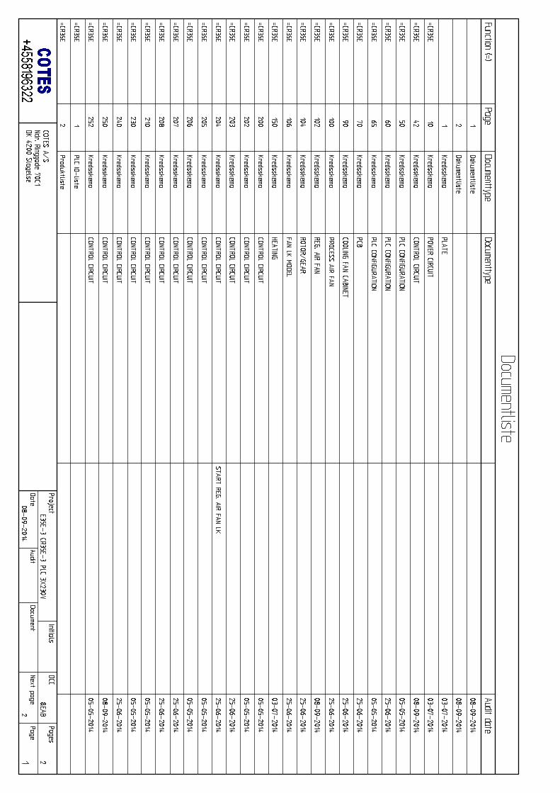
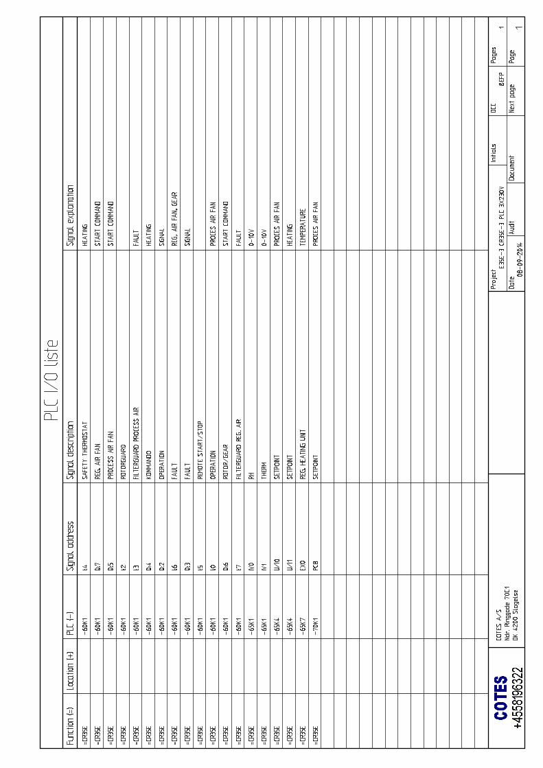
ELECTRICAL DIAGRAMS APPENDIX
COTES C35E/C35D OPERATING AND SERVICE HANDBOOK page 3/101
SECTION 1 / GENERAL BACKGROUND
ABOUT THIS HANDBOOK
This is the installation and service handbook for your Cotes dehumidifier.
You should read the whole handbook before installing and/or starting the dehumidifier unit for the
first time. It is important that you and your colleagues are familiar with the correct operating
procedures and all precautionary safety measures, in order to avoid any damage to the
surroundings, materials or installations, as well as to prevent any personal injury.
This handbook is mainly intended for use by technicians who install and operate this Cotes
dehumidifier unit, who carry out preventive maintenance and who replace defective parts.
Anyone using Cotes dehumidifier units, or whose responsibilities include supervising their
operation, will also benefit from reading this handbook and from consulting it as a practical help
should the need arise.
Product number for this handbook
The product number of this particular service handbook is 140712.
This is the number you need to give us if you would like to order additional copies for your staff,
colleagues or service personnel, or for technical staff from outside your company.
COTES C35E/C35D OPERATING AND SERVICE HANDBOOK page 4/101
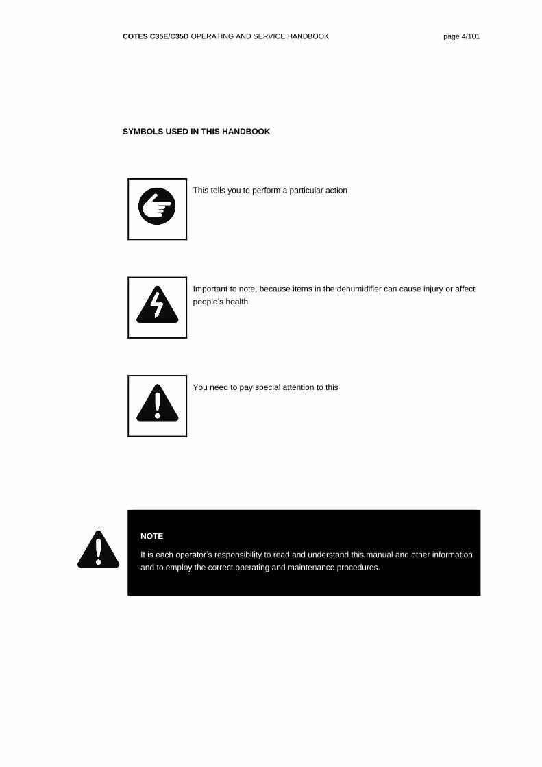
SYMBOLS USED IN THIS HANDBOOK
This tells you to perform a particular action
Important to note, because items in the dehumidifier can cause injury or affect
people’s health
You need to pay special attention to this
NOTE
It is each operator’s responsibility to read and understand this manual and other information
and to employ the correct operating and maintenance procedures.
COTES C35E/C35D OPERATING AND SERVICE HANDBOOK page 5/101
ABOUT MANAGING HUMIDITY
Cotes humidity management technology – cost-effective and energy-efficient
The moisture in the air all around us has surprising – and often costly – effects on the materials, structures and processes at the heart of virtually all business processes and industrial activity.
Cotes humidity management technologies enable you to control the levels of moisture in the air inside any building, installation or facility, using only a bare minimum of energy.
And effective control of the basic parameters for your operations is good business.
COTES C35E/C35D OPERATING AND SERVICE HANDBOOK page 6/101
ABOUT COTES
World leader
Cotes is one of the world’s leading experts in the field of adsorption dehumidification, providing technology and expertise that enable companies to achieve better control of the humidity always present in the air.
Better management of the humidity in the air also makes it possible to improve and optimise a wide range of industrial processes, prevent damage and corrosion in many types of structures, and reduce energy consumption in all kinds of installations where air specifications are important.
Big benefits
Cotes dehumidification units provide exceptional advantages.
• Our know-how and experience make sure each customer gets the right equipment to tackle all the practical needs and operating priorities associated with the specific installation
• Our units are exceptionally reliable, and can withstand even harsh treatment unusually well
• They are very easy to maintain and service
• They only use a minimum of energy in order to achieve maximum effect.
We aim to provide our customers with the most technically effective and energy-efficient solution for the best price. This ensures the best possible return on investment, as well as peace of mind about having made the best decision.
COTES C35E/C35D OPERATING AND SERVICE HANDBOOK page 7/101
SECTION 2 / THE DEHUMIDIFIER
ABOUT THE COTES C35E/C35D RANGE OF DEHUMIDIFIERS
The Cotes C35E/C35D range of dehumidifiers is designed and configured for a wide range of industrial uses. Prominent among these is humidity management in storage facilities and basement areas, in water works and in many kinds of process industry in which stable, well-controlled air conditions are crucial.
The C35E series is specifically configured to minimise the overall energy consumption of the dehumidification process, whereas the C35D is configured to ensure as dry air as possible.
The units in the C35E/C35D range are designed for easy cleaning and for configuring with extra features like cooling/heating coils and extra filters if this is needed.
Design priorities
The Cotes C35E/C35D range features an eye-catching modern industrial design appearance, along with exceptional reliability.
It is designed to ensure the unhindered passage of air through the unit, which reduces
energy consumption
pressure losses
noise levels.
All the components, ancillary equipment and features are optimised for better performance, exceptional service life and ease of maintenance.
Capacities
The Cotes C35E/C35D range currently features models with air volumes of between 405 m3/hour
and 1,000 m3/hour.
At process air inlet conditions of 20°C and 60% relative humidity (%RH), the capacities (the
amount of water which can be removed from the air) of these units are between 3.3 kg/hour and
5.6 kg/hour.
Configuration priorities
The Cotes C35E/C35D range is available with 4 different PLC configurations – PLC-A, PLC-B, PLC-C and PLC-D.
PLC-A
The PLC-A configuration provides:
High dehumidification capacity
High energy efficiency
Stainless steel cabinet
Easy installation
Low-noise running
COTES C35E/C35D OPERATING AND SERVICE HANDBOOK page 8/101
Low maintenance costs, reducing the overall operating cost
Easy cleaning
Attachment of one external humidity sensor
3.5-inch touch display
Service indication, to keep track of any need for maintenance
Hour counter, to keep track of how long the unit has been in operation
Over-heating alarm
PLC-B
In addition to the PLC-A features, the PLC-B configuration provides:
Mechanical service alarm for rotor and filters
Control of regeneration air fan, making installation easier
Capacity control / modulating heat control
Measuring and controlling dew point temperature
Datalogging for keeping track of conditions in the space where the unit is installed
Timer program
Network connectivity (optional)
Monitoring and control via smartphone app (optional)
Monitoring and control by Cotes service centre (optional)
PLC-C
In addition to the PLC-A and PLC-B features, the PLC-C configuration provides:
Control of process air fan, making installation easier
Monitoring and control of air flows [m3/hour]
Energy-saving program, for situations where energy consumption is the prime consideration
Low-noise program, for situations where silence is the prime consideration
CUSTOM program, for situation where dehumidifier parameters needs to be controlled
PLC-D
In addition to the PLC-A and PLC-B features, the PLC-D configuration provides:
Accurate control of humidity level, whether % relative humidity or specific humidity [g/kg]
Continuous measurement of capacity
Detailed energy-saving program, for situations where energy consumption is the prime consideration
COTES C35E/C35D OPERATING AND SERVICE HANDBOOK page 9/101
Operating conditions
For the process and regeneration air inlet, the following operating conditions must be respected:
Relative humidity 0–100%
Temperature 0–35°C
Pressure Ambient ± 100 Pa
It is only possible to deviate from these ranges if such deviations were specifically mentioned
when the order was placed, and special considerations have been incorporated into the unit in
order to deal with this.
NOTE
Operating conditions for air inlet flows must be respected.
Storage conditions
For storing the dehumidifier, the following conditions must be respected:
Relative humidity 0–90%
Temperature -20°C to 50°C
It is only possible to deviate from these ranges if such deviations were specifically mentioned
when the order was placed, and special considerations have been incorporated into the unit in
order to deal with this.
NOTE
Storage conditions for dehumidifier must be respected.
COTES C35E/C35D OPERATING AND SERVICE HANDBOOK page 10/101
HOW IT WORKS
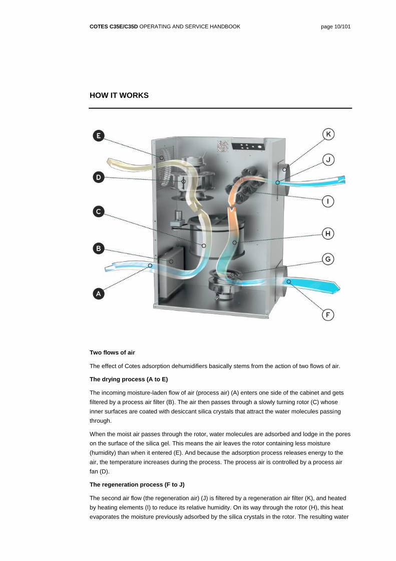
Two flows of air
The effect of Cotes adsorption dehumidifiers basically stems from the action of two flows of air.
The drying process (A to E)
The incoming moisture-laden flow of air (process air) (A) enters one side of the cabinet and gets
filtered by a process air filter (B). The air then passes through a slowly turning rotor (C) whose
inner surfaces are coated with desiccant silica crystals that attract the water molecules passing
through.
When the moist air passes through the rotor, water molecules are adsorbed and lodge in the pores
on the surface of the silica gel. This means the air leaves the rotor containing less moisture
(humidity) than when it entered (E). And because the adsorption process releases energy to the
air, the temperature increases during the process. The process air is controlled by a process air
fan (D).
The regeneration process (F to J)
The second air flow (the regeneration air) (J) is filtered by a regeneration air filter (K), and heated
by heating elements (I) to reduce its relative humidity. On its way through the rotor (H), this heat
evaporates the moisture previously adsorbed by the silica crystals in the rotor. The resulting water
COTES C35E/C35D OPERATING AND SERVICE HANDBOOK page 11/101
vapour now leaves the dehumidifier in the outgoing regeneration air (F). The regeneration air is
controlled by a regeneration air fan (G).
Fans
All units in the C35E/C35D range of adsorption dehumidifiers are fitted with two fans as standard.
For the PLC-B configuration, the speed of the regeneration air fan can be controlled.
For the PLC-C and PLC-D configuration, the flows of process air and regeneration air flows can be controlled.
Cotes adsorption dehumidifiers are always configured with a certain amount of “external pressure” to make sure that ducting does not cause a reduction in the amount of air.
For details about the fans fitted to this particular Cotes dehumidifier, see page 24.
Filters
All models of Cotes adsorption dehumidifiers are fitted with filters to remove undesirable particles
or other pollutants from the incoming process and regeneration air.
Filters of the G4 class are fitted to Cotes C35E/C35D units.as standard to filter the incoming
process air.
For details about the filters fitted to this particular Cotes dehumidifier, see page 24.
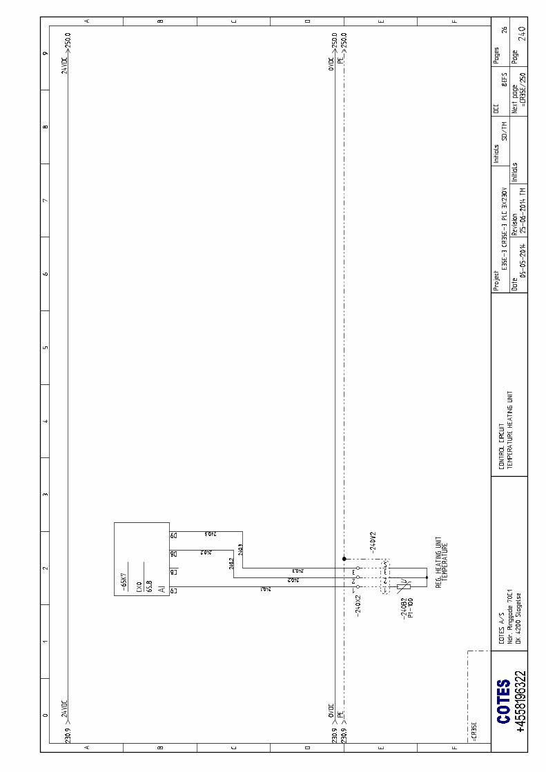
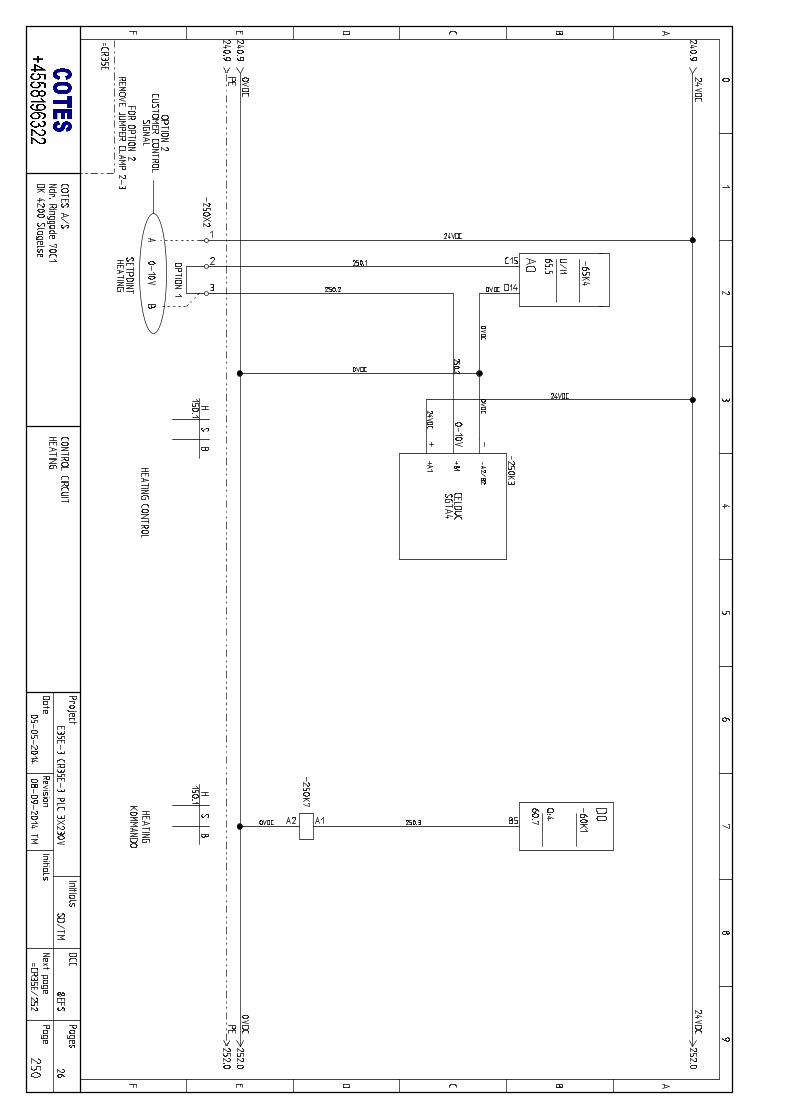
Heating units
Cotes C35E/C35D dehumidifiers are fitted with electrical heating units as standard, in order to
control the temperature of the regeneration air entering the unit.
For details about heating units fitted to this particular Cotes dehumidifier, see page 24.
Post-heating units
Being able to control the exact specifications of the air leaving the dehumidifier enables you to
extract maximum benefit from Cotes humidity management.
If it is important to keep the process air at a consistently high temperature, a post-heating unit can
be fitted after the adsorption rotor, as optional equipment.
A post-heating unit is normally in combination with a post-cooling coil, in order to ensure 100%
control of both relative humidity and temperature.
Post-heating units can be retrofitted to C35E/C35D dehumidifiers with the PLC-C and PLC-D
configuration.
For details about any post-heating units fitted to this particular Cotes dehumidifier, please contact
your Cotes dealer, or Cotes.
COTES C35E/C35D OPERATING AND SERVICE HANDBOOK page 12/101
Pre-cooling units
Being able to control the exact specifications of the air entering the dehumidifier enables you to
extract maximum benefit from Cotes humidity management.
Cotes C35E/C35D dehumidifiers can therefore be fitted with cooling units to reduce and/or control
the temperature of the dry air entering and leaving the dehumidifier.
A cooling unit fitted before the adsorption rotor is particularly beneficial if the incoming process air
is very warm and humid. In such cases, some of the water in the air condenses and the efficiency
of the adsorption rotor increases. A cooling unit fitted before the adsorption rotor can also be an
advantage if the outgoing process air has to be especially dry.
Pre-cooling units can be retrofitted to C35E/C35D dehumidifiers with the PLC-C and PLC-D
configuration.
For details about any pre-cooling units fitted to this particular Cotes dehumidifier, please contact
your Cotes dealer, or Cotes.
Post-cooling unit
Cotes C35E/C35D units can be fitted with post-cooling/heating units to maintain full control of the
temperature of the dry air leaving the dehumidifier.
Post-cooling/heating units can be retrofitted to C35E/C35D dehumidifiers with the PLC-C and
PLC-D configuration.
For details about any cooling units fitted to this particular Cotes dehumidifier, please contact your
Cotes dealer, or Cotes.
Heat recovery unit
Cotes adsorption dehumidifiers can be fitted with heat exchangers to make sure that part of the
thermal energy from the regeneration air leaving the unit is extracted, and reused for preheating
the incoming regeneration air.
The heat exchangers are placed in an external box equipped with inlets and outlets for the
incoming and outgoing regeneration air.
The heat recovery unit can save as much as 20–25% on energy consumption, and can be fitted to
C35E/C35D dehumidifiers with the PLC-B, PLC-C and PLC-D configuration.
The heat recovery unit can be fitted to C35E/C35D dehumidifiers with the PLC-A configuration, but
you have to install the appropriate ducting and damper for outgoing regeneration air.
For details about the heat recovery units fitted to this particular Cotes dehumidifier, please contact
your Cotes dealer, or Cotes.
COTES C35E/C35D OPERATING AND SERVICE HANDBOOK page 13/101
Water condensation units
Cotes adsorption dehumidifiers can be fitted with water condensation units in order to condense
some of the water from the regeneration air leaving the dehumidifier. This is beneficial when a
regeneration air outlet is not desired good idea or cannot be fitted.
When a water condensation unit is fitted, the regeneration air forms a closed circuit, using ambient
air passing through heat exchangers to cool the regeneration air to below condensation
temperature.
The water condensation unit can be fitted to C35E/C35D dehumidifiers with the PLC-B, PLC-C
and PLC-D configurations.
For details about water condensation units fitted to this particular Cotes dehumidifier, please
contact your Cotes dealer, or Cotes.
COTES C35E/C35D OPERATING AND SERVICE HANDBOOK page 14/101
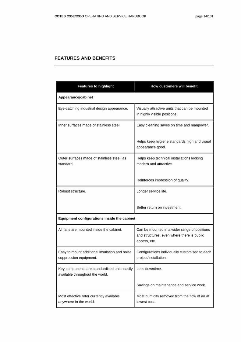
FEATURES AND BENEFITS
Features to highlight How customers will benefit
Appearance/cabinet
Eye-catching industrial design appearance. Visually attractive units that can be mounted
in highly visible positions.
Inner surfaces made of stainless steel. Easy cleaning saves on time and manpower.
Helps keep hygiene standards high and visual
appearance good.
Outer surfaces made of stainless steel, as
standard.
Helps keep technical installations looking
modern and attractive.
Reinforces impression of quality.
Robust structure. Longer service life.
Better return on investment.
Equipment configurations inside the cabinet
All fans are mounted inside the cabinet. Can be mounted in a wider range of positions
and structures, even where there is public
access, etc.
Easy to mount additional insulation and noise
suppression equipment.
Configurations individually customised to each
project/installation.
Key components are standardised units easily
available throughout the world.
Less downtime.
Savings on maintenance and service work.
Most effective rotor currently available
anywhere in the world.
Most humidity removed from the flow of air at
lowest cost.
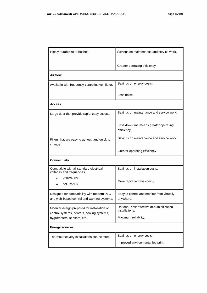
COTES C35E/C35D OPERATING AND SERVICE HANDBOOK page 15/101
Highly durable rotor bushes. Savings on maintenance and service work.
Greater operating efficiency.
Air flow
Available with frequency-controlled ventilator. Savings on energy costs.
Less noise
Access
Large door that provide rapid, easy access. Savings on maintenance and service work.
Less downtime means greater operating
efficiency.
Filters that are easy to get out, and quick to
change.
Savings on maintenance and service work.
Greater operating efficiency.
Connectivity
Compatible with all standard electrical voltages and frequencies
COTES C35E/C35D OPERATING AND SERVICE HANDBOOK page 18/101
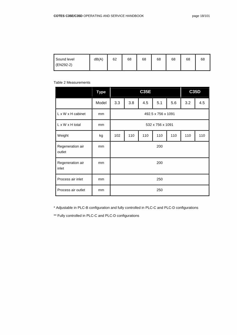
Sound level
(EN292-2)
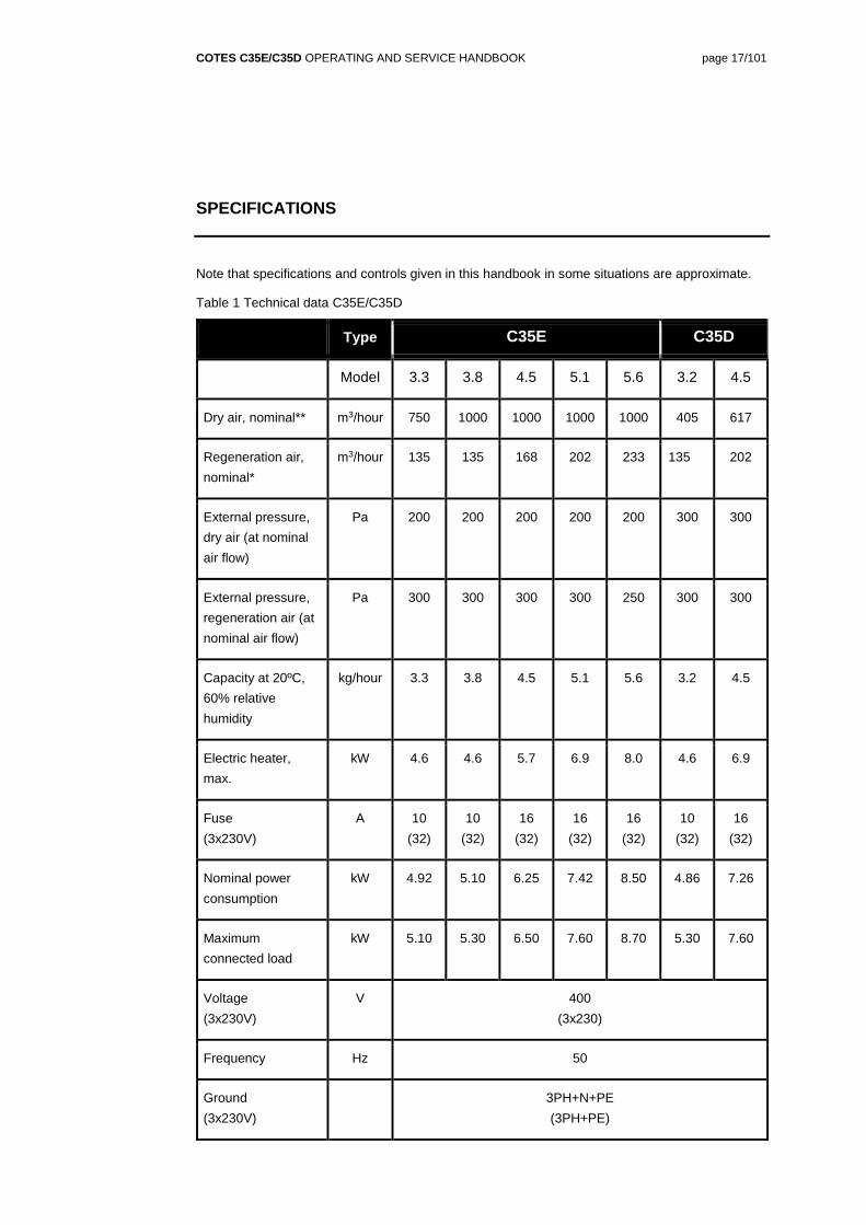
dB(A) 62 68 68 68 68 68 68
Table 2 Measurements
Type C35E C35D
Model 3.3 3.8 4.5 5.1 5.6 3.2 4.5
L x W x H cabinet mm 492.5 x 756 x 1091
L x W x H total mm 532 x 756 x 1091
Weight kg 102 110 110 110 110 110 110
Regeneration air
outlet
mm 200
Regeneration air
inlet
mm 200
Process air inlet mm 250
Process air outlet mm 250
* Adjustable in PLC-B configuration and fully controlled in PLC-C and PLC-D configurations
** Fully controlled in PLC-C and PLC-D configurations
COTES C35E/C35D OPERATING AND SERVICE HANDBOOK page 19/101
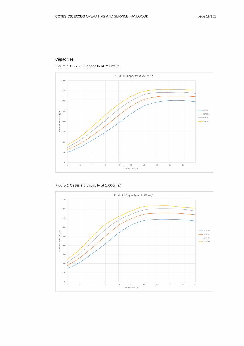
Capacities
Figure 1 C35E-3.3 capacity at 750m3/h
Figure 2 C35E-3.9 capacity at 1.000m3/h
COTES C35E/C35D OPERATING AND SERVICE HANDBOOK page 20/101
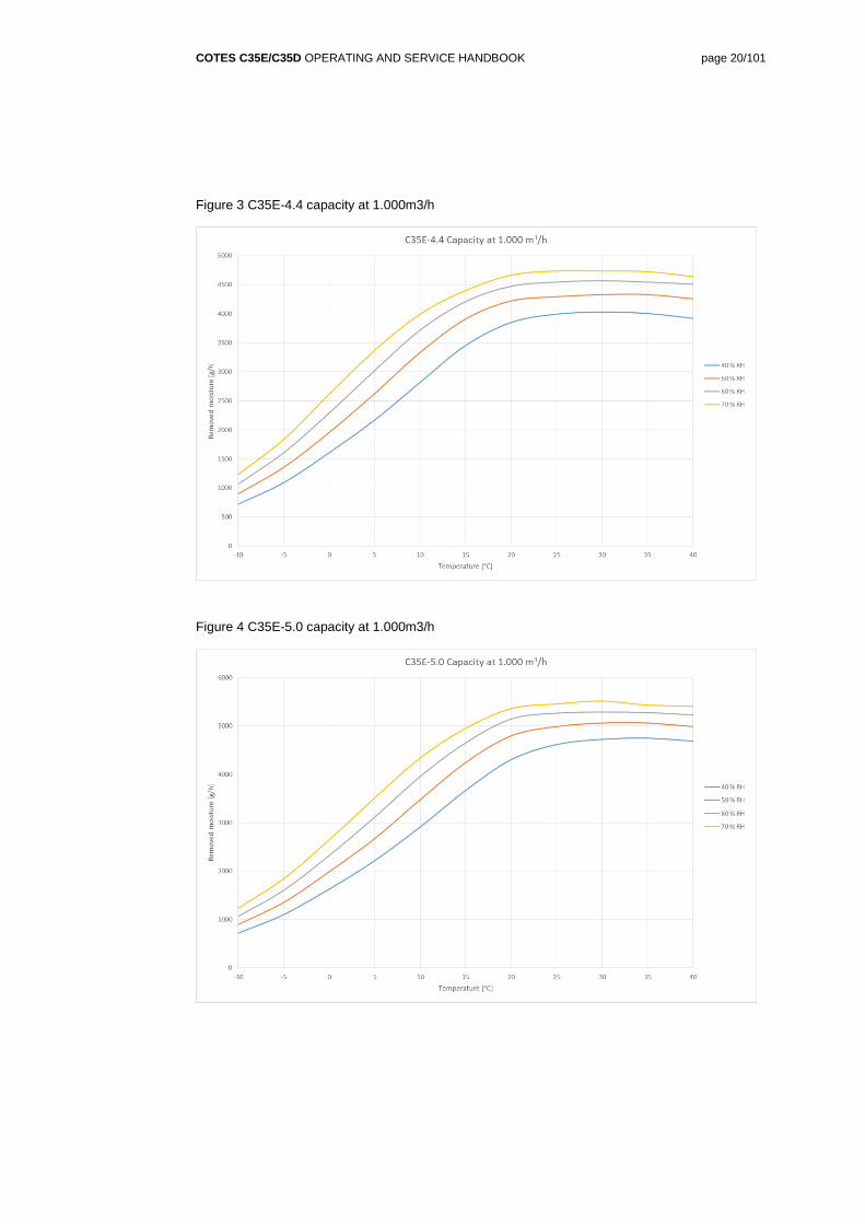
Figure 3 C35E-4.4 capacity at 1.000m3/h
Figure 4 C35E-5.0 capacity at 1.000m3/h
COTES C35E/C35D OPERATING AND SERVICE HANDBOOK page 21/101
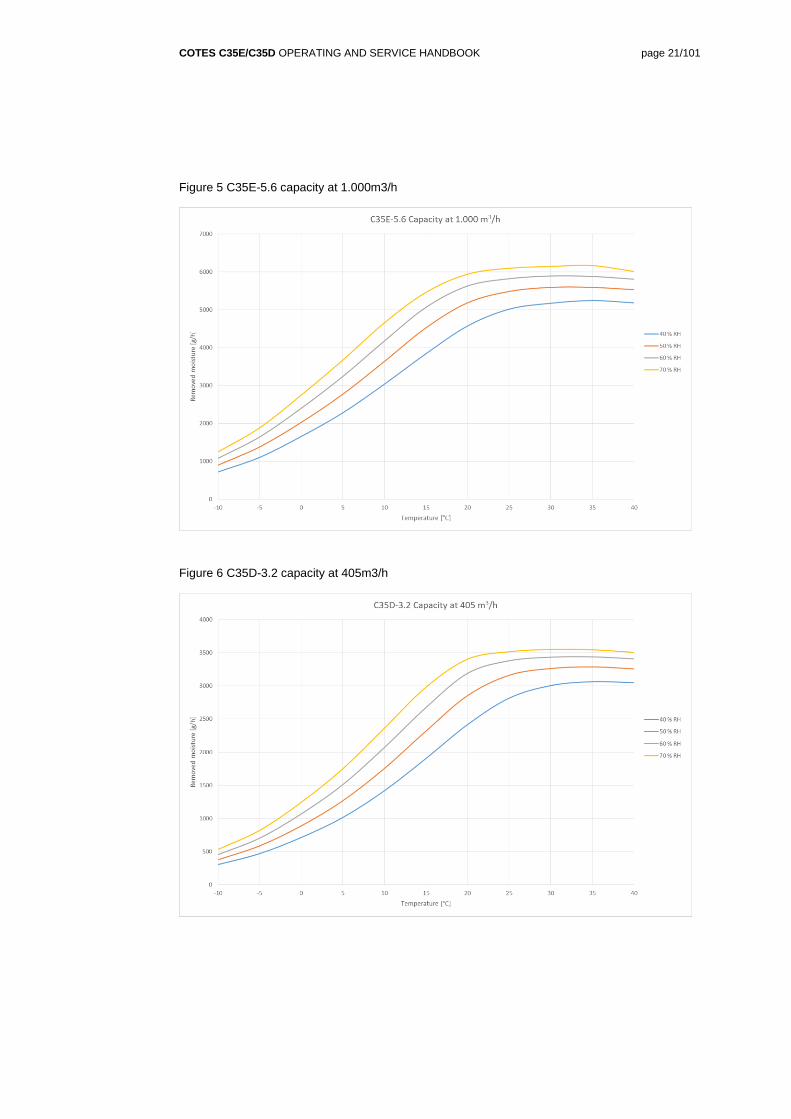
Figure 5 C35E-5.6 capacity at 1.000m3/h
Figure 6 C35D-3.2 capacity at 405m3/h
COTES C35E/C35D OPERATING AND SERVICE HANDBOOK page 22/101
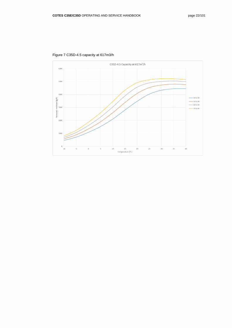
Figure 7 C35D-4.5 capacity at 617m3/h
COTES C35E/C35D OPERATING AND SERVICE HANDBOOK page 23/101
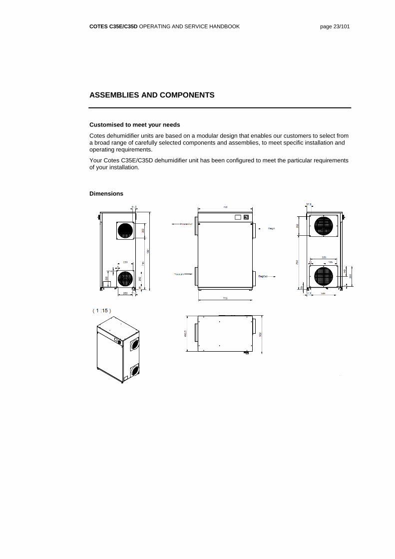
ASSEMBLIES AND COMPONENTS
Customised to meet your needs
Cotes dehumidifier units are based on a modular design that enables our customers to select from a broad range of carefully selected components and assemblies, to meet specific installation and operating requirements.
Your Cotes C35E/C35D dehumidifier unit has been configured to meet the particular requirements of your installation.
Dimensions
COTES C35E/C35D OPERATING AND SERVICE HANDBOOK page 24/101
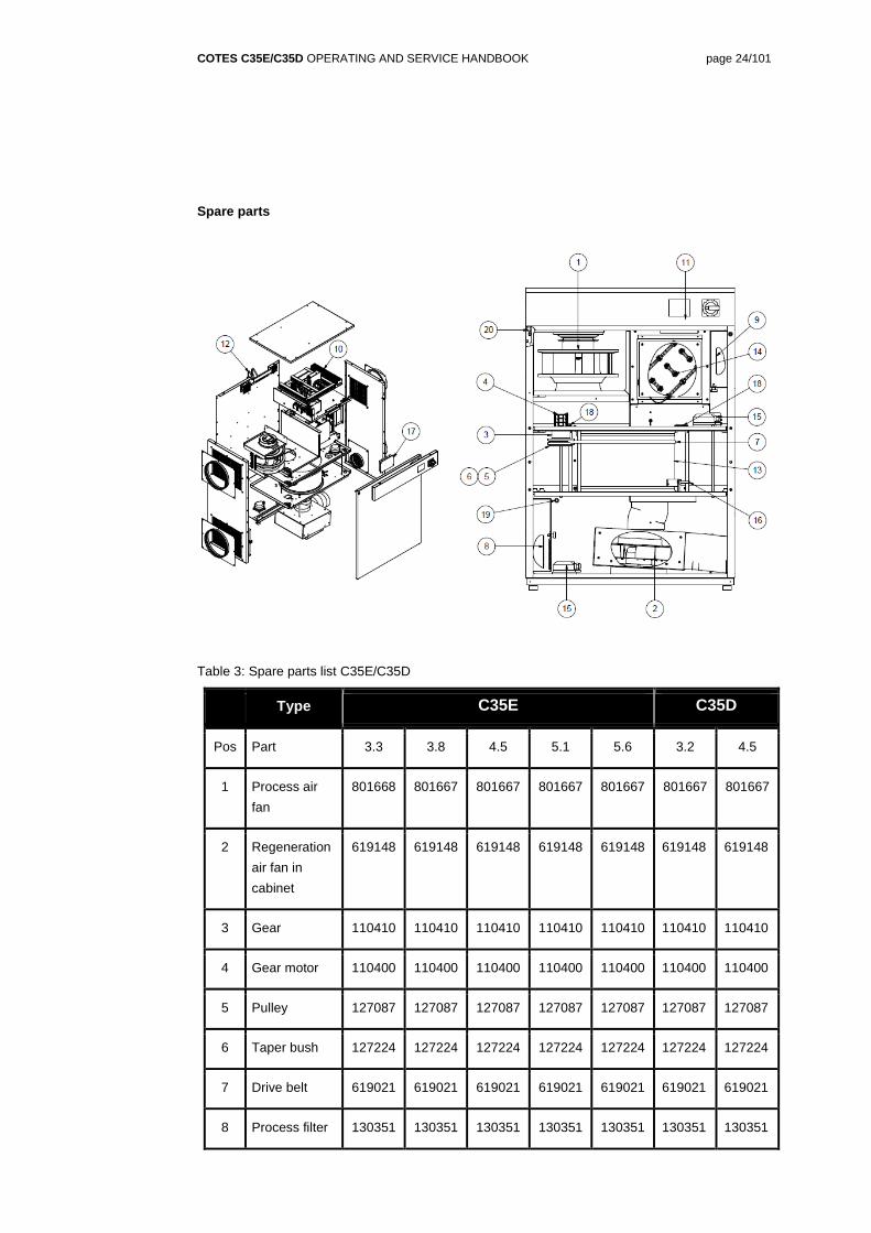
COTES C35E/C35D OPERATING AND SERVICE HANDBOOK page 26/101
COTES C35E/C35D OPERATING AND SERVICE HANDBOOK page 27/101
SOUND LEVELS
Sound dampening and silencers
Please check the maximum sound level permitted for the particular installation you are working
with, and select the sound dampening and silencers needed for the dry air outlet duct and the
regeneration air outlet duct accordingly.
Sound levels for the particular dehumidifier can be found on page 1817.
Measuring sound levels
Sound levels for Cotes dehumidifiers are measured in accordance with the provisions of the
EN292-2 standard.
While the sound level is being measured, the dehumidifier is placed on the floor. Ducts for
regeneration air and for incoming air/outgoing air are installed and led out of the measuring room.
The sound level is then measured 1 metre outside the front of the cabinet (outside the large
cabinet cover), and 1.6 metres above the floor.
COTES C35E/C35D OPERATING AND SERVICE HANDBOOK page 28/101
SECTION 4 / INSTALLATION
HOW TO INSTALL THIS DEHUMIDIFIER
Removing the packaging
Cotes C35E/C35D dehumidifier units are delivered in a cardboard box. Please dispose of this
packaging responsibly, and recycle it if at all possible.
Handling
Cotes dehumidifier units are built to be very robust, so there is no need for special handling, apart
from normal sensible care and attention.
Note the weight of the dehumidifier as specified on page 17. We recommend that you use a forklift
to move the dehumidifier around and place it in position.
Where to mount this dehumidifier
Cotes adsorption dehumidifiers are designed for installation indoors.
The back of the dehumidifier should be placed against an outer wall to make it easier to install the
regeneration air ducts.
The three other sides of the unit should have at least 1 metre of unobstructed access, for easy
service and maintenance.
Where not to mount it
Unless it has been arranged with Cotes and special considerations have been made, the unit
should not be placed outdoors.
The unit should not be placed inside an office or in other locations where the sound pressure level
must be kept to a minimum.
NOTE
Dehumidifier must be placed indoors, and protected from rain and water.
COTES C35E/C35D OPERATING AND SERVICE HANDBOOK page 29/101
Things to be careful about
Electrical work should only be carried out by an authorised electrician.
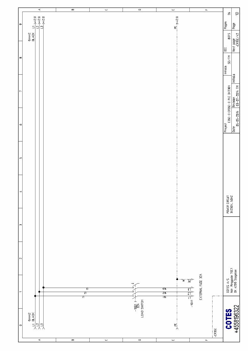
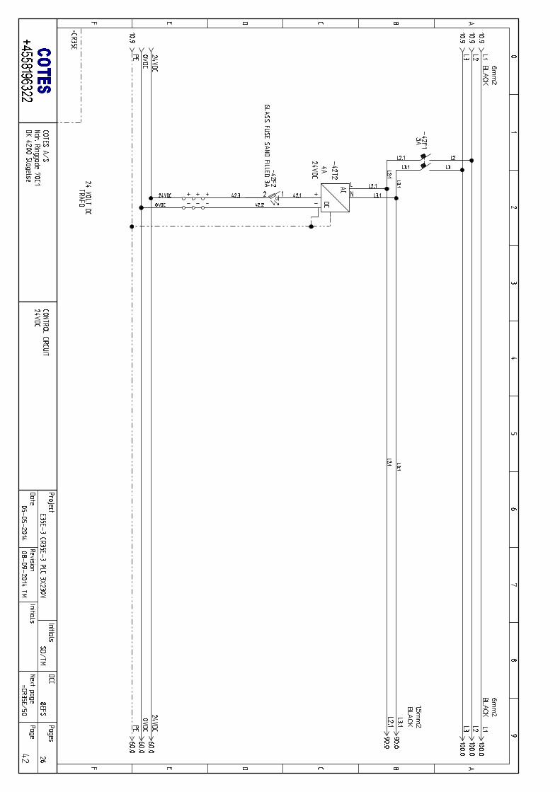
Connections needed – electrical
First, make sure that the main switch is OFF.
Now the power circuit cable can be connected to the unit.
Connections needed – ductwork
The ductwork for the process air should be selected with regard to the external pressure available
from the process air fan and the space available for ducting. A 250mm-diameter duct is normally
recommended for the process air flow.
When installed, the process air flow should be adjusted by means of a damper.
In PLC-C and PLC-D configurations, the process air fan is equipped with a frequency converter,
which makes dampers on the process air side unnecessary.
The regeneration air should be led to and taken from the outdoors.
The ductwork for the regeneration air should be selected with regard to the external pressure
available from the regeneration air fan and the space available for ducting. A 200mm-diameter
duct is normally recommended for the regeneration air flow.
NOTE
Electrical work should only be carried out by an authorised electrician.
NOTE
Make sure power is switched off before installing and servicing.
NOTE
To ensure low pressure drop and low sound pressure levels, please request assistance
from a company that specialises in ductwork.
COTES C35E/C35D OPERATING AND SERVICE HANDBOOK page 30/101
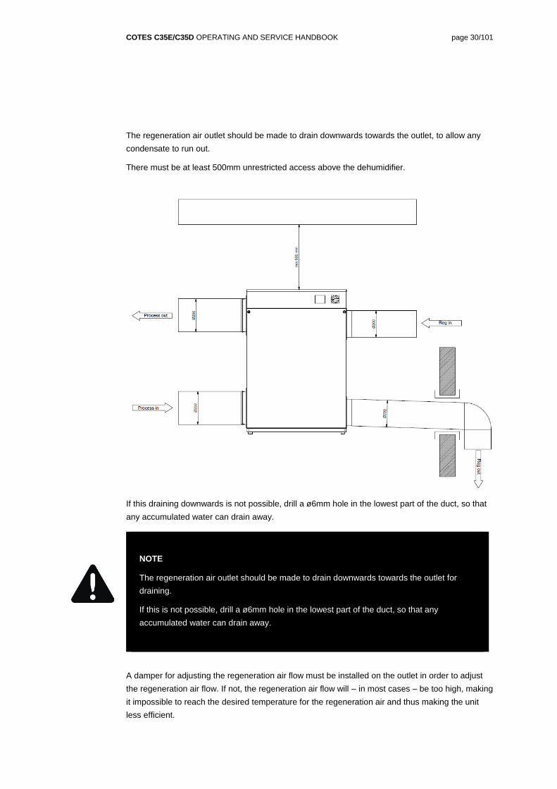
The regeneration air outlet should be made to drain downwards towards the outlet, to allow any
condensate to run out.
There must be at least 500mm unrestricted access above the dehumidifier.
If this draining downwards is not possible, drill a ø6mm hole in the lowest part of the duct, so that
any accumulated water can drain away.
A damper for adjusting the regeneration air flow must be installed on the outlet in order to adjust
the regeneration air flow. If not, the regeneration air flow will – in most cases – be too high, making
it impossible to reach the desired temperature for the regeneration air and thus making the unit
less efficient.
NOTE
The regeneration air outlet should be made to drain downwards towards the outlet for
draining.
If this is not possible, drill a ø6mm hole in the lowest part of the duct, so that any
accumulated water can drain away.
COTES C35E/C35D OPERATING AND SERVICE HANDBOOK page 31/101
In PLC-B, PLC-C and PLC-D configurations, the regeneration air fans are equipped with frequency
converters, which makes dampers on the regeneration air side unnecessary. In PLC-C and PLC-D
configurations, the flow of regeneration air will adjust automatically.
Safety precautions
The smallest units in the C35E/C35D range weigh approximately 102–110 kg and should therefore
only be moved using a forklift or similar equipment
Any work in the electrical box should only be carried out by authorised electricians.
Any pipe connections to and from the coils should only be carried out by authorised plumbers.
COTES C35E/C35D OPERATING AND SERVICE HANDBOOK page 32/101
HOW TO COMMISSION THIS DEHUMIDIFIER
Procedure
a) Check the electrical installation before starting the dehumidifier, switch on the mains
switch.
Check the voltage between the terminals L1, L2, L3 (= 400V or 230V for 3 x 230V
dehumidifiers)
Check one of the phases and Neutral (= 230V)
Is the ground cable connected, and of the correct specifications?
Is any hygrometer (if fitted) correctly connected?
b) To check the connected duct system
Is the recommended damper installed in the regeneration air outlet duct (PLC-A only)
Is the recommended damper installed in the process air outlet duct (PLC-A and PLC-B
only)
Do the regeneration air outlet ducts drain away from the dehumidifier, to make sure that
any condensed water flows away?
If the regeneration air outlet does not drain away from the dehumidifier, check whether
there is a 6mm-diameter hole drilled in the lowest part of the duct, so that any
accumulated water can drain away.
c) Suggested damper positions/air flow settings at commissioning
Dampers/settings should be set in the following positions.
PLC-A configuration:
o Damper at process air outlet: Fully open.
o Damper at regeneration air outlet: Fully open.
PLC-B configuration:
o Damper at process air outlet: Fully open.
NOTE
Only trained/authorised electricians are allowed to carry out any work required in the
electronics box of this Cotes dehumidifier.
When the cover of the electronics box is open, the power supply must be switched off at the
mains switch.
COTES C35E/C35D OPERATING AND SERVICE HANDBOOK page 33/101
o Regeneration air fan speed 50% (default value)
PLC-C and PLC-D configuration:
o Process air fan automatically adjusts to preset airflow (no damper needed)
o Regeneration air fan automatically adjusts to preset airflow (no damper needed)
d) If the dehumidifier starts up as described above, then go to e)
If the dehumidifier does not start, you should check the humidity set point. If set point is higher
than measured by the humidity sensor, the dehumidifier will not start (unless the “Always On”
program has been chosen – see below).
e) Once the dehumidifier is operating, you should adjust the air flows
PLC-A configuration:
Adjust the dampers on process air and regeneration air so the incoming air flow matches the
nominal values given on page 17. Check the air flows using a suitable instrument (pitot
pipe/thermoanemometer or similar) in the duct.
PLC-B configuration:
Adjust the damper on the process air so the incoming air flow matches the nominal value
given on page 17. Check the air flow using a suitable instrument (pitot
pipe/thermoanemometer or similar) in the duct.
Adjust the regeneration air fan speed until the incoming air flow matches the nominal
value given on page 17. Check the air flow using a suitable instrument (pitot
pipe/thermoanemometer or similar) in the duct.
PLC-C and PLC-D configuration:
In the PLC-C and PLC-D configuration, the dehumidifier is self-adjusting, and adjusts
according to default air flows.
COTES C35E/C35D OPERATING AND SERVICE HANDBOOK page 34/101
SECTION 5 / OPERATION
HOW TO OPERATE THIS DEHUMIDIFIER
The dehumidifier needs to be turned on at the main switch.
After a while the PLC overview screen will appear.
Overview menu
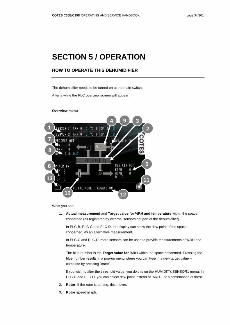
What you see:
1. Actual measurement and Target value for %RH and temperature within the space
concerned (as registered by external sensors not part of the dehumidifier).
In PLC-B, PLC-C and PLC-D, the display can show the dew point of the space
concerned, as an alternative measurement.
In PLC-C and PLC-D, more sensors can be used to provide measurements of %RH and
temperature.
The blue number is the Target value for %RH within the space concerned. Pressing the
blue number results in a pop-up menu where you can type in a new target value –
complete by pressing ”enter”.
If you wish to alter the threshold value, you do this on the HUMIDITY/SENSOR1 menu. In
PLC-C and PLC-D, you can select dew point instead of %RH – or a combination of these.
2. Rotor. If the rotor is turning, this moves.
3. Rotor speed in rph.
13
9 3 4
2
12
5
10
11
6
7
1
8
COTES C35E/C35D OPERATING AND SERVICE HANDBOOK page 35/101
4. Regeneration air temperature. Shows the temperature of the heated regeneration air. If
the temperature is shown in red, something is overheating.
5. Regeneration air flow (PLC-C and PLC-D only). The white number indicates the air flow,
given by the chosen program. In the CUSTOM program the number is blue, and can be
changed. Pressing the blue number results in a pop-up menu where you can type in a
new target value – complete by pressing ”enter”. The value can be in m3/hour (based on
normal m3 (20˚C)) or kg/hour.
In PLC-B (only) the regeneration air fan can be adjusted in % in relation to maximum
setting. This should only be used for initial adjustment, and should not be changed
subsequently.
6. Inflow process air conditions (PLC-C and PLC-D only). For PLC-C, temperature only.
7. Adjustment of process flow (PLC-C and PLC-D only). The white number indicates the
air flow, given by the chosen program.
In the CUSTOM program the number is blue, and can be changed. Pressing the blue
number results in a pop-up menu where you can type in a new target value – complete
by pressing ”enter”. The value can be in m3/hour or kg/hour.
8. Adjustment of process air conditions, measured in g/kg (PLC-D only). The blue
number is where you adjust the target value. Pressing the blue number results in a pop-
up menu where you can type in a new target value – complete by pressing ”enter”.
9. Regeneration air filter (PLC-B, PLC-C and PLC-D only). If this is yellow, this filter should
soon be replaced. If this is red, the service interval has been exceeded, or the filter
sensor is showing an alarm.
10. Process air filter (PLC-B, PLC-C and PLC-D only). If this is yellow, this filter should soon
be replaced. If this is red, the service interval has been exceeded, or the filter sensor is
showing an alarm
11. Alarm/warning. Green = everything is ok. Yellow = warning = the target is not reached
yet, or a service will soon be required.
Red = alarm = there is a fault or malfunction somewhere. The most likely causes are that
the regeneration air heater is over-heating, the filter is blocked, or the service interval has
been exceeded.
12. Actual mode. Indication of chosen program. See more page 41.
13. Return to main menu
Note that to change values, you will be asked to enter an operator code (1234 is standard/default).
COTES C35E/C35D OPERATING AND SERVICE HANDBOOK page 36/101
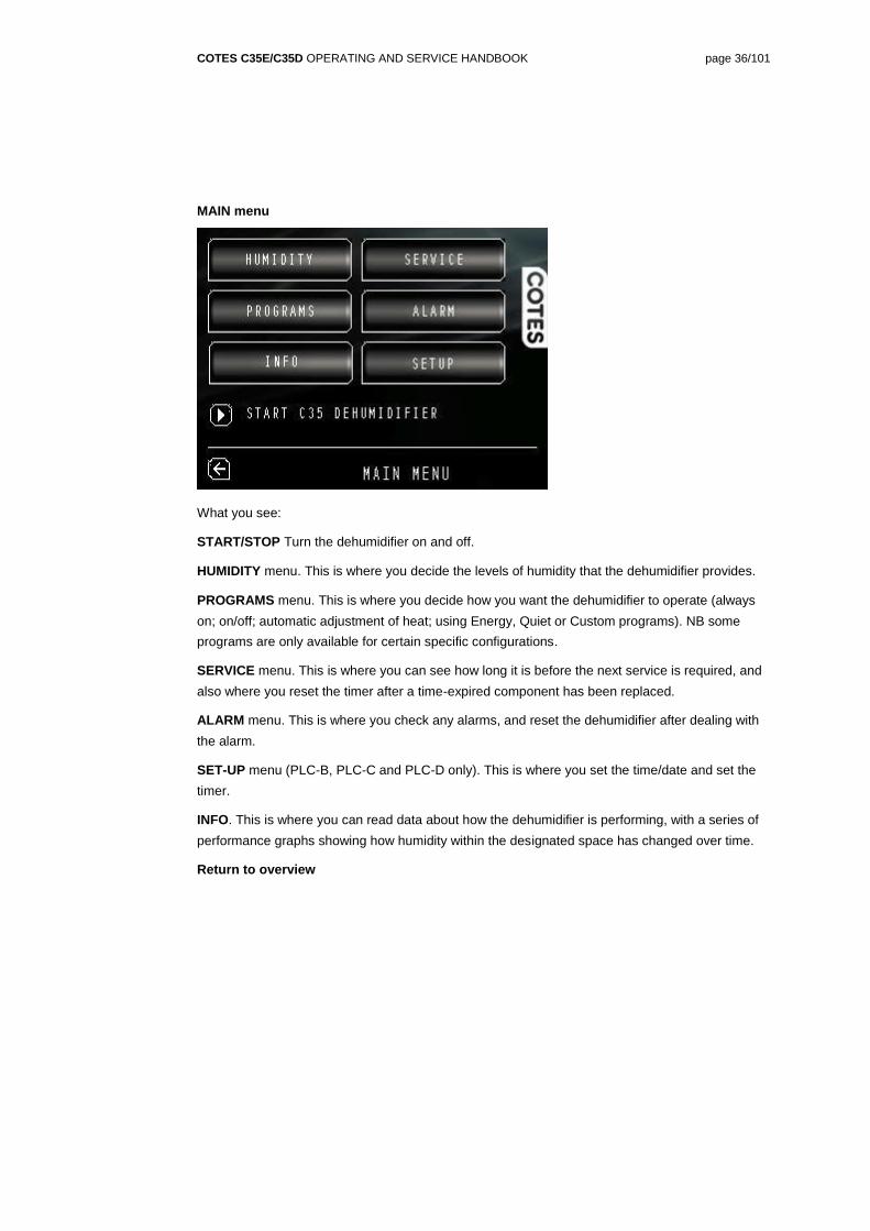
MAIN menu
What you see:
START/STOP Turn the dehumidifier on and off.
HUMIDITY menu. This is where you decide the levels of humidity that the dehumidifier provides.
PROGRAMS menu. This is where you decide how you want the dehumidifier to operate (always
on; on/off; automatic adjustment of heat; using Energy, Quiet or Custom programs). NB some
programs are only available for certain specific configurations.
SERVICE menu. This is where you can see how long it is before the next service is required, and
also where you reset the timer after a time-expired component has been replaced.
ALARM menu. This is where you check any alarms, and reset the dehumidifier after dealing with
the alarm.
SET-UP menu (PLC-B, PLC-C and PLC-D only). This is where you set the time/date and set the
timer.
INFO. This is where you can read data about how the dehumidifier is performing, with a series of
performance graphs showing how humidity within the designated space has changed over time.
Return to overview
COTES C35E/C35D OPERATING AND SERVICE HANDBOOK page 37/101
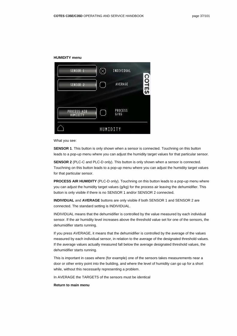
HUMIDITY menu
What you see:
SENSOR 1. This button is only shown when a sensor is connected. Touchning on this button
leads to a pop-up menu where you can adjust the humidity target values for that particular sensor.
SENSOR 2 (PLC-C and PLC-D only). This button is only shown when a sensor is connected.
Touchning on this button leads to a pop-up menu where you can adjust the humidity target values
for that particular sensor.
PROCESS AIR HUMIDITY (PLC-D only). Touchning on this button leads to a pop-up menu where
you can adjust the humidity target values (g/kg) for the process air leaving the dehumidifier. This
button is only visible if there is no SENSOR 1 and/or SENSOR 2 connected.
INDIVIDUAL and AVERAGE buttons are only visible if both SENSOR 1 and SENSOR 2 are
connected. The standard setting is INDIVIDUAL.
INDIVIDUAL means that the dehumidifier is controlled by the value measured by each individual
sensor. If the air humidity level increases above the threshold value set for one of the sensors, the
dehumidifier starts running.
If you press AVERAGE, it means that the dehumidifier is controlled by the average of the values
measured by each individual sensor, in relation to the average of the designated threshold values.
If the average values actually measured fall below the average designated threshold values, the
dehumidifier starts running.
This is important in cases where (for example) one of the sensors takes measurements near a
door or other entry point into the building, and where the level of humidity can go up for a short
while, without this necessarily representing a problem.
In AVERAGE the TARGETS of the sensors must be identical
Return to main menu
COTES C35E/C35D OPERATING AND SERVICE HANDBOOK page 38/101
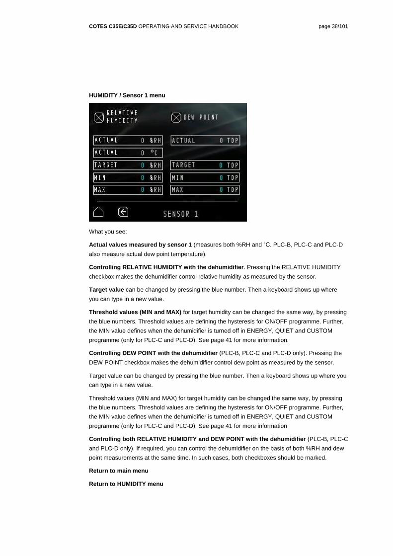
HUMIDITY / Sensor 1 menu
What you see:
Actual values measured by sensor 1 (measures both %RH and ˚C. PLC-B, PLC-C and PLC-D
also measure actual dew point temperature).
Controlling RELATIVE HUMIDITY with the dehumidifier. Pressing the RELATIVE HUMIDITY
checkbox makes the dehumidifier control relative humidity as measured by the sensor.
Target value can be changed by pressing the blue number. Then a keyboard shows up where
you can type in a new value.
Threshold values (MIN and MAX) for target humidity can be changed the same way, by pressing
the blue numbers. Threshold values are defining the hysteresis for ON/OFF programme. Further,
the MIN value defines when the dehumidifier is turned off in ENERGY, QUIET and CUSTOM
programme (only for PLC-C and PLC-D). See page 41 for more information.
Controlling DEW POINT with the dehumidifier (PLC-B, PLC-C and PLC-D only). Pressing the
DEW POINT checkbox makes the dehumidifier control dew point as measured by the sensor.
Target value can be changed by pressing the blue number. Then a keyboard shows up where you
can type in a new value.
Threshold values (MIN and MAX) for target humidity can be changed the same way, by pressing
the blue numbers. Threshold values are defining the hysteresis for ON/OFF programme. Further,
the MIN value defines when the dehumidifier is turned off in ENERGY, QUIET and CUSTOM
programme (only for PLC-C and PLC-D). See page 41 for more information
Controlling both RELATIVE HUMIDITY and DEW POINT with the dehumidifier (PLC-B, PLC-C
and PLC-D only). If required, you can control the dehumidifier on the basis of both %RH and dew
point measurements at the same time. In such cases, both checkboxes should be marked.
Return to main menu
Return to HUMIDITY menu
COTES C35E/C35D OPERATING AND SERVICE HANDBOOK page 39/101
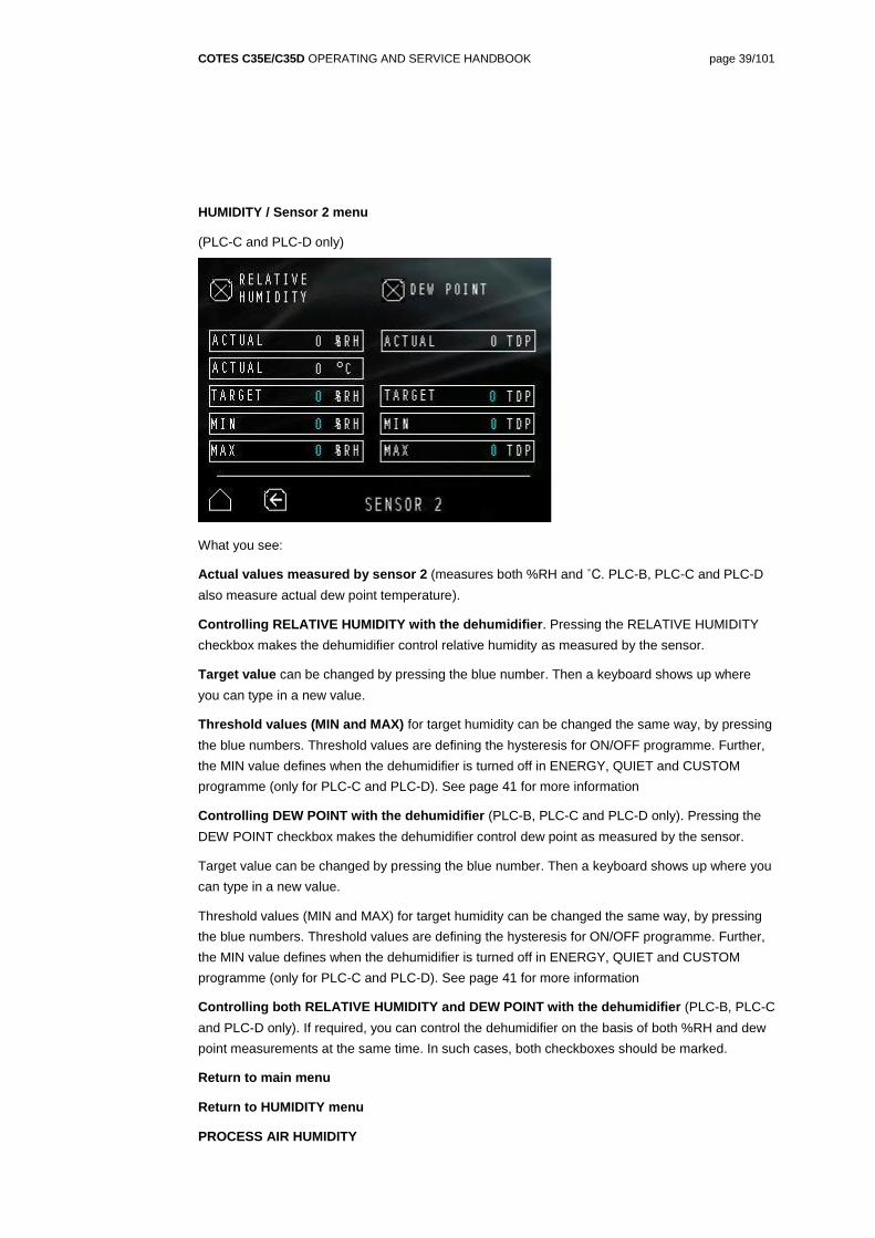
HUMIDITY / Sensor 2 menu
(PLC-C and PLC-D only)
What you see:
Actual values measured by sensor 2 (measures both %RH and ˚C. PLC-B, PLC-C and PLC-D
also measure actual dew point temperature).
Controlling RELATIVE HUMIDITY with the dehumidifier. Pressing the RELATIVE HUMIDITY
checkbox makes the dehumidifier control relative humidity as measured by the sensor.
Target value can be changed by pressing the blue number. Then a keyboard shows up where
you can type in a new value.
Threshold values (MIN and MAX) for target humidity can be changed the same way, by pressing
the blue numbers. Threshold values are defining the hysteresis for ON/OFF programme. Further,
the MIN value defines when the dehumidifier is turned off in ENERGY, QUIET and CUSTOM
programme (only for PLC-C and PLC-D). See page 41 for more information
Controlling DEW POINT with the dehumidifier (PLC-B, PLC-C and PLC-D only). Pressing the
DEW POINT checkbox makes the dehumidifier control dew point as measured by the sensor.
Target value can be changed by pressing the blue number. Then a keyboard shows up where you
can type in a new value.
Threshold values (MIN and MAX) for target humidity can be changed the same way, by pressing
the blue numbers. Threshold values are defining the hysteresis for ON/OFF programme. Further,
the MIN value defines when the dehumidifier is turned off in ENERGY, QUIET and CUSTOM
programme (only for PLC-C and PLC-D). See page 41 for more information
Controlling both RELATIVE HUMIDITY and DEW POINT with the dehumidifier (PLC-B, PLC-C
and PLC-D only). If required, you can control the dehumidifier on the basis of both %RH and dew
point measurements at the same time. In such cases, both checkboxes should be marked.
Return to main menu
Return to HUMIDITY menu
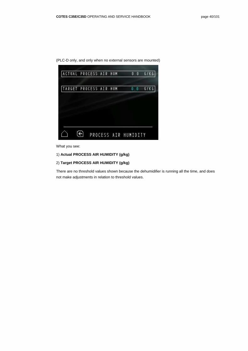
PROCESS AIR HUMIDITY
COTES C35E/C35D OPERATING AND SERVICE HANDBOOK page 40/101
(PLC-D only, and only when no external sensors are mounted)
What you see:
1) Actual PROCESS AIR HUMIDITY (g/kg)
2) Target PROCESS AIR HUMIDITY (g/kg)
There are no threshold values shown because the dehumidifier is running all the time, and does
not make adjustments in relation to threshold values.
COTES C35E/C35D OPERATING AND SERVICE HANDBOOK page 41/101
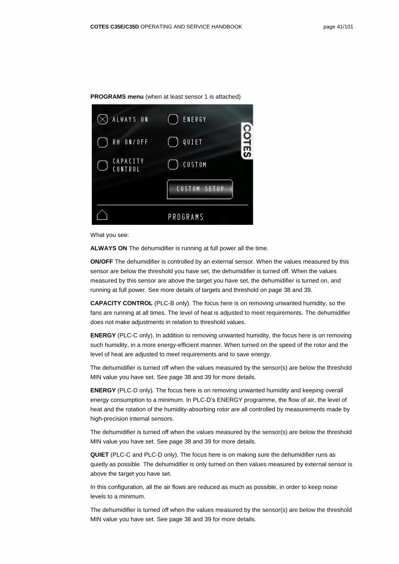
PROGRAMS menu (when at least sensor 1 is attached)
What you see:
ALWAYS ON The dehumidifier is running at full power all the time.
ON/OFF The dehumidifier is controlled by an external sensor. When the values measured by this
sensor are below the threshold you have set, the dehumidifier is turned off. When the values
measured by this sensor are above the target you have set, the dehumidifier is turned on, and
running at full power. See more details of targets and threshold on page 38 and 39.
CAPACITY CONTROL (PLC-B only). The focus here is on removing unwanted humidity, so the
fans are running at all times. The level of heat is adjusted to meet requirements. The dehumidifier
does not make adjustments in relation to threshold values.
ENERGY (PLC-C only). In addition to removing unwanted humidity, the focus here is on removing
such humidity, in a more energy-efficient manner. When turned on the speed of the rotor and the
level of heat are adjusted to meet requirements and to save energy.
The dehumidifier is turned off when the values measured by the sensor(s) are below the threshold
MIN value you have set. See page 38 and 39 for more details.
ENERGY (PLC-D only). The focus here is on removing unwanted humidity and keeping overall
energy consumption to a minimum. In PLC-D’s ENERGY programme, the flow of air, the level of
heat and the rotation of the humidity-absorbing rotor are all controlled by measurements made by
high-precision internal sensors.
The dehumidifier is turned off when the values measured by the sensor(s) are below the threshold
MIN value you have set. See page 38 and 39 for more details.
QUIET (PLC-C and PLC-D only). The focus here is on making sure the dehumidifier runs as
quietly as possible. The dehumidifier is only turned on then values measured by external sensor is
above the target you have set.
In this configuration, all the air flows are reduced as much as possible, in order to keep noise
levels to a minimum.
The dehumidifier is turned off when the values measured by the sensor(s) are below the threshold
MIN value you have set. See page 38 and 39 for more details.
COTES C35E/C35D OPERATING AND SERVICE HANDBOOK page 42/101
CUSTOM SETUP (PLC-C and PLC-D only). In this configuration, you can adjust all the values
individually, within predefined limits. See page 45 for more details.
The dehumidifier is turned off when the values measured by the sensor(s) are below the threshold
MIN value you have set. See page 38 and 39 for more details.
Return to main menu
COTES C35E/C35D OPERATING AND SERVICE HANDBOOK page 43/101
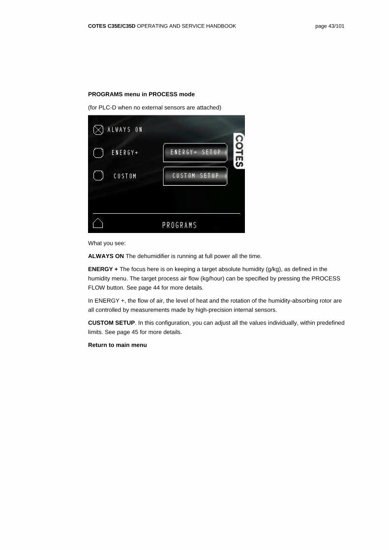
PROGRAMS menu in PROCESS mode
(for PLC-D when no external sensors are attached)
What you see:
ALWAYS ON The dehumidifier is running at full power all the time.
ENERGY + The focus here is on keeping a target absolute humidity (g/kg), as defined in the
humidity menu. The target process air flow (kg/hour) can be specified by pressing the PROCESS
FLOW button. See page 44 for more details.
In ENERGY +, the flow of air, the level of heat and the rotation of the humidity-absorbing rotor are
all controlled by measurements made by high-precision internal sensors.
CUSTOM SETUP. In this configuration, you can adjust all the values individually, within predefined
limits. See page 45 for more details.
Return to main menu
COTES C35E/C35D OPERATING AND SERVICE HANDBOOK page 44/101
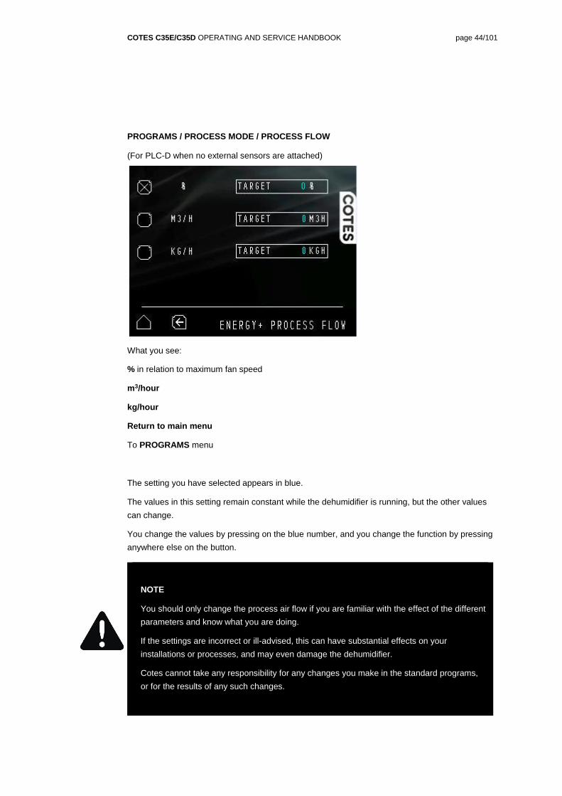
PROGRAMS / PROCESS MODE / PROCESS FLOW
(For PLC-D when no external sensors are attached)
What you see:
% in relation to maximum fan speed
m3/hour
kg/hour
Return to main menu
To PROGRAMS menu
The setting you have selected appears in blue.
The values in this setting remain constant while the dehumidifier is running, but the other values
can change.
You change the values by pressing on the blue number, and you change the function by pressing
anywhere else on the button.
NOTE
You should only change the process air flow if you are familiar with the effect of the different
parameters and know what you are doing.
If the settings are incorrect or ill-advised, this can have substantial effects on your
installations or processes, and may even damage the dehumidifier.
Cotes cannot take any responsibility for any changes you make in the standard programs,
or for the results of any such changes.
COTES C35E/C35D OPERATING AND SERVICE HANDBOOK page 45/101
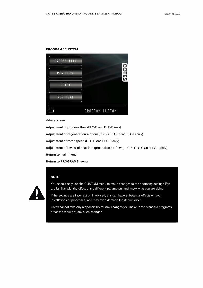
PROGRAM / CUSTOM
What you see:
Adjustment of process flow (PLC-C and PLC-D only)
Adjustment of regeneration air flow (PLC-B, PLC-C and PLC-D only)
Adjustment of rotor speed (PLC-C and PLC-D only)
Adjustment of levels of heat in regeneration air flow (PLC-B, PLC-C and PLC-D only)
Return to main menu
Return to PROGRAMS menu
NOTE
You should only use the CUSTOM menu to make changes to the operating settings if you
are familiar with the effect of the different parameters and know what you are doing.
If the settings are incorrect or ill-advised, this can have substantial effects on your
installations or processes, and may even damage the dehumidifier.
Cotes cannot take any responsibility for any changes you make in the standard programs,
or for the results of any such changes.
COTES C35E/C35D OPERATING AND SERVICE HANDBOOK page 46/101
PROGRAMS / CUSTOM / PROCESS flow
What you see:
% in relation to maximum fan speed (PLC-C and PLC-D only)
m3/hour (PLC-C and PLC-D only)
kg/hour (PLC-C and PLC-D only)
Return to main menu
To CUSTOM menu
The setting you have selected appears in blue.
The values in this setting remain constant while the dehumidifier is running, but the other values
can change.
You change the values by pressing on the blue number, and you change the function by pressing
anywhere else on the button.
In CUSTOM programme the dehumidifier is turned off when the values measured by the sensor(s)
are below the threshold MIN value you have set. See page 38 and 39 for more details.
NOTE
You should only change the process air flow if you are familiar with the effect of the different
parameters and know what you are doing.
If the settings are incorrect or ill-advised, this can have substantial effects on your
installations or processes, and may even damage the dehumidifier.
Cotes cannot take any responsibility for any changes you make in the standard programs,
or for the results of any such changes.
COTES C35E/C35D OPERATING AND SERVICE HANDBOOK page 47/101
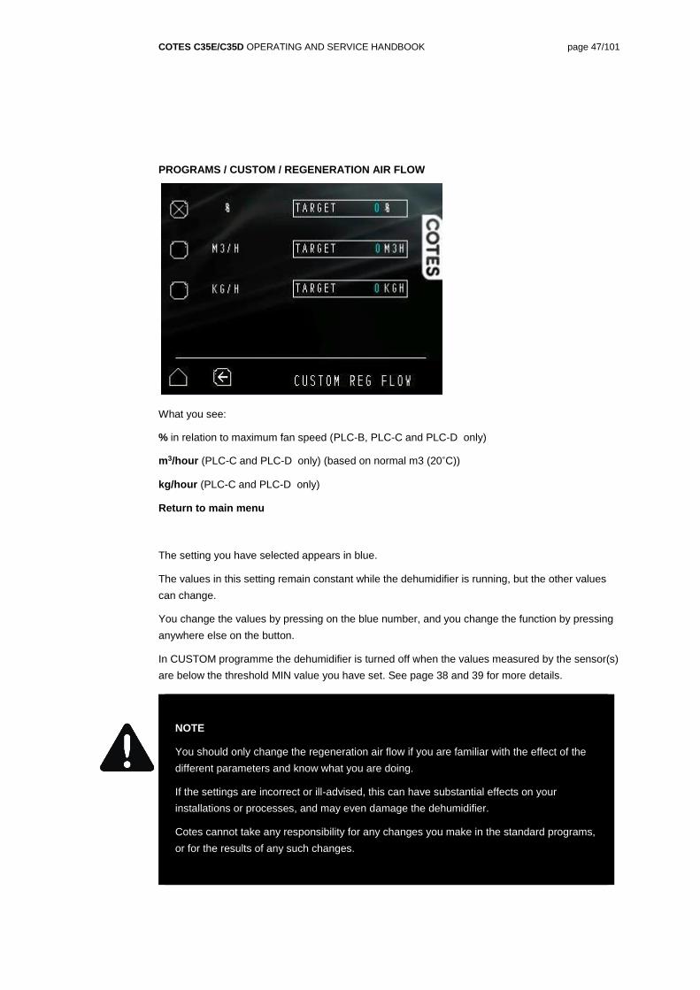
PROGRAMS / CUSTOM / REGENERATION AIR FLOW
What you see:
% in relation to maximum fan speed (PLC-B, PLC-C and PLC-D only)
m3/hour (PLC-C and PLC-D only) (based on normal m3 (20˚C))
kg/hour (PLC-C and PLC-D only)
Return to main menu
The setting you have selected appears in blue.
The values in this setting remain constant while the dehumidifier is running, but the other values
can change.
You change the values by pressing on the blue number, and you change the function by pressing
anywhere else on the button.
In CUSTOM programme the dehumidifier is turned off when the values measured by the sensor(s)
are below the threshold MIN value you have set. See page 38 and 39 for more details.
NOTE
You should only change the regeneration air flow if you are familiar with the effect of the
different parameters and know what you are doing.
If the settings are incorrect or ill-advised, this can have substantial effects on your
installations or processes, and may even damage the dehumidifier.
Cotes cannot take any responsibility for any changes you make in the standard programs,
or for the results of any such changes.
COTES C35E/C35D OPERATING AND SERVICE HANDBOOK page 48/101
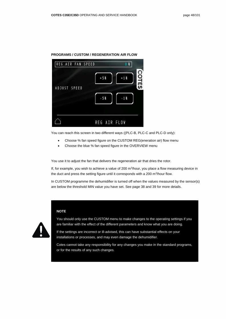
PROGRAMS / CUSTOM / REGENERATION AIR FLOW
You can reach this screen in two different ways ((PLC-B, PLC-C and PLC-D only):
Choose % fan speed figure on the CUSTOM REG(eneration air) flow menu
Choose the blue % fan speed figure in the OVERVIEW menu
You use it to adjust the fan that delivers the regeneration air that dries the rotor.
If, for example, you wish to achieve a value of 200 m3/hour, you place a flow measuring device in
the duct and press the setting figure until it corresponds with a 200 m3/hour flow.
In CUSTOM programme the dehumidifier is turned off when the values measured by the sensor(s)
are below the threshold MIN value you have set. See page 38 and 39 for more details.
NOTE
You should only use the CUSTOM menu to make changes to the operating settings if you
are familiar with the effect of the different parameters and know what you are doing.
If the settings are incorrect or ill-advised, this can have substantial effects on your
installations or processes, and may even damage the dehumidifier.
Cotes cannot take any responsibility for any changes you make in the standard programs,
or for the results of any such changes.
COTES C35E/C35D OPERATING AND SERVICE HANDBOOK page 49/101
PROGRAMS / CUSTOM / ROTOR
What you see:
RPH – this is where you select rotor speed (PLC-C and PLC-D only), by pressing the blue
number, and entering the new value.
AUTO – automatically calculates the ideal rotor speed (rph)
Return to main menu
In CUSTOM programme the dehumidifier is turned off when the values measured by the sensor(s)
are below the threshold MIN value you have set. See page 38 and 39 for more details.
NOTE
You should only change rotor speed if you are familiar with the effect of the different
parameters and know what you are doing.
If the settings are incorrect or ill-advised, this can have substantial effects on your
installations or processes, and may even damage the dehumidifier.
Cotes cannot take any responsibility for any changes you make in the standard programs,
or for the results of any such changes.
COTES C35E/C35D OPERATING AND SERVICE HANDBOOK page 50/101
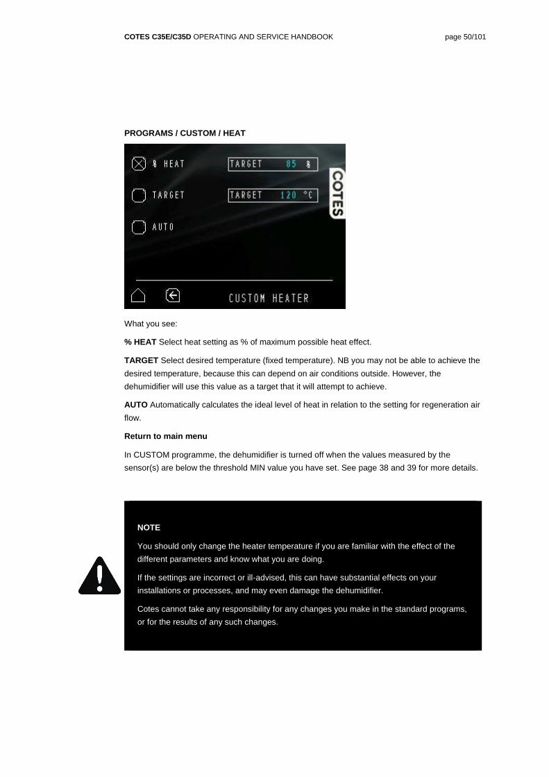
PROGRAMS / CUSTOM / HEAT
What you see:
% HEAT Select heat setting as % of maximum possible heat effect.
TARGET Select desired temperature (fixed temperature). NB you may not be able to achieve the
desired temperature, because this can depend on air conditions outside. However, the
dehumidifier will use this value as a target that it will attempt to achieve.
AUTO Automatically calculates the ideal level of heat in relation to the setting for regeneration air
flow.
Return to main menu
In CUSTOM programme, the dehumidifier is turned off when the values measured by the
sensor(s) are below the threshold MIN value you have set. See page 38 and 39 for more details.
NOTE
You should only change the heater temperature if you are familiar with the effect of the
different parameters and know what you are doing.
If the settings are incorrect or ill-advised, this can have substantial effects on your
installations or processes, and may even damage the dehumidifier.
Cotes cannot take any responsibility for any changes you make in the standard programs,
or for the results of any such changes.
COTES C35E/C35D OPERATING AND SERVICE HANDBOOK page 51/101
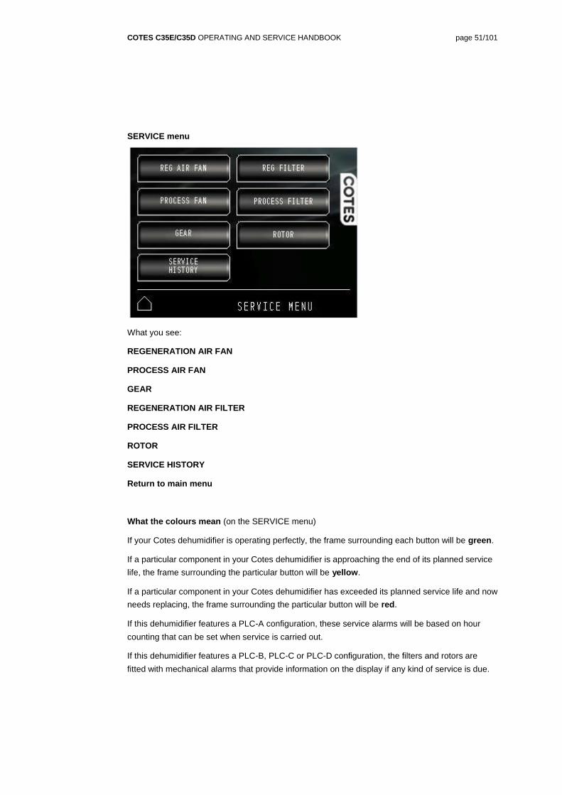
SERVICE menu
What you see:
REGENERATION AIR FAN
PROCESS AIR FAN
GEAR
REGENERATION AIR FILTER
PROCESS AIR FILTER
ROTOR
SERVICE HISTORY
Return to main menu
What the colours mean (on the SERVICE menu)
If your Cotes dehumidifier is operating perfectly, the frame surrounding each button will be green.
If a particular component in your Cotes dehumidifier is approaching the end of its planned service
life, the frame surrounding the particular button will be yellow.
If a particular component in your Cotes dehumidifier has exceeded its planned service life and now
needs replacing, the frame surrounding the particular button will be red.
If this dehumidifier features a PLC-A configuration, these service alarms will be based on hour
counting that can be set when service is carried out.
If this dehumidifier features a PLC-B, PLC-C or PLC-D configuration, the filters and rotors are
fitted with mechanical alarms that provide information on the display if any kind of service is due.
COTES C35E/C35D OPERATING AND SERVICE HANDBOOK page 52/101
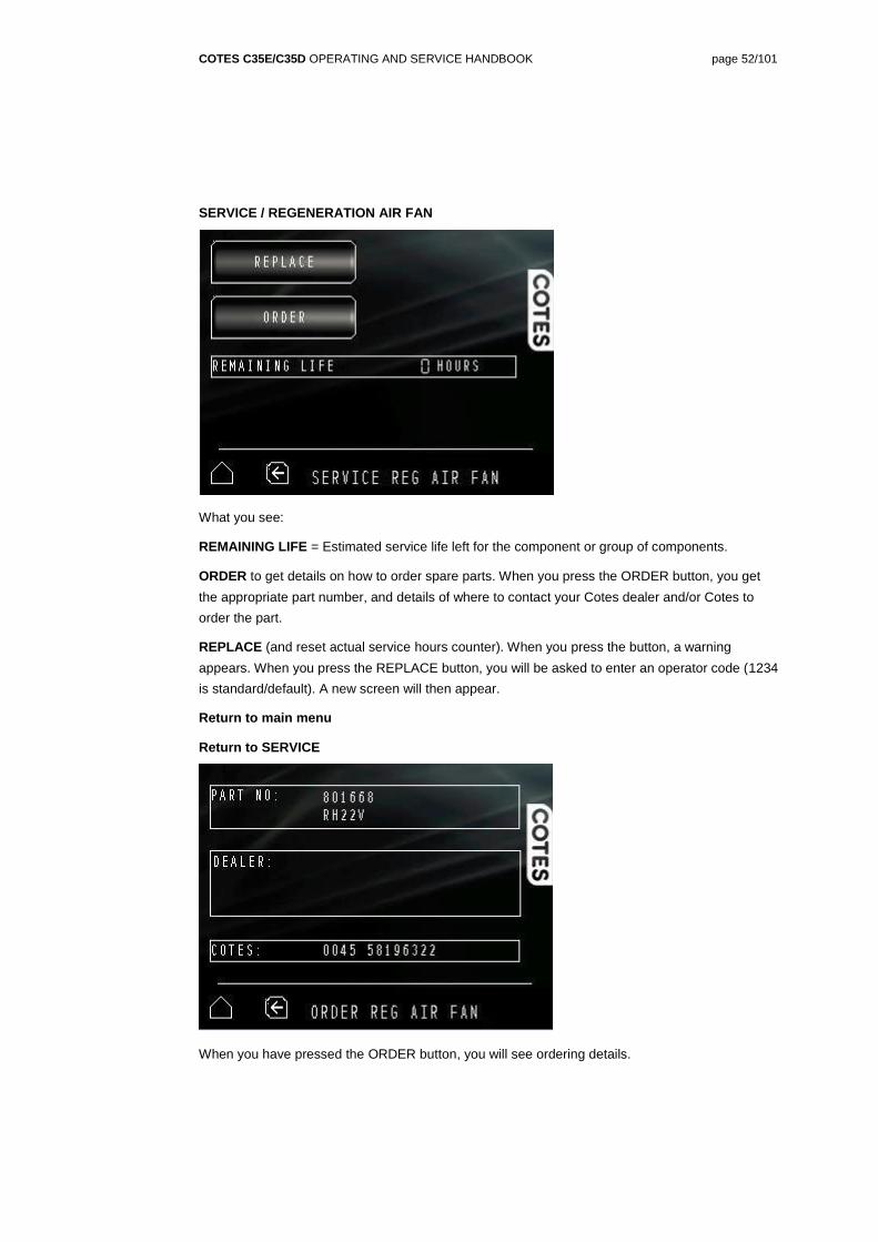
SERVICE / REGENERATION AIR FAN
What you see:
REMAINING LIFE = Estimated service life left for the component or group of components.
ORDER to get details on how to order spare parts. When you press the ORDER button, you get
the appropriate part number, and details of where to contact your Cotes dealer and/or Cotes to
order the part.
REPLACE (and reset actual service hours counter). When you press the button, a warning
appears. When you press the REPLACE button, you will be asked to enter an operator code (1234
is standard/default). A new screen will then appear.
Return to main menu
Return to SERVICE
When you have pressed the ORDER button, you will see ordering details.
COTES C35E/C35D OPERATING AND SERVICE HANDBOOK page 53/101
When you have pressed the REPLACE button and entered the appropriate operator code, you will
see the screen shown above.
This is where you reset the remaining service life for the component, using a drop-down keyboard.
COTES C35E/C35D OPERATING AND SERVICE HANDBOOK page 54/101
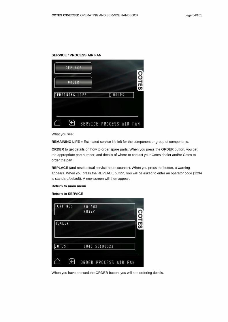
SERVICE / PROCESS AIR FAN
What you see:
REMAINING LIFE = Estimated service life left for the component or group of components.
ORDER to get details on how to order spare parts. When you press the ORDER button, you get
the appropriate part number, and details of where to contact your Cotes dealer and/or Cotes to
order the part.
REPLACE (and reset actual service hours counter). When you press the button, a warning
appears. When you press the REPLACE button, you will be asked to enter an operator code (1234
is standard/default). A new screen will then appear.
Return to main menu
Return to SERVICE
When you have pressed the ORDER button, you will see ordering details.
COTES C35E/C35D OPERATING AND SERVICE HANDBOOK page 55/101
When you have pressed the REPLACE button and entered the appropriate operator code, you will
see the screen shown above.
This is where you reset the remaining service life for the component, using a drop-down keyboard.
COTES C35E/C35D OPERATING AND SERVICE HANDBOOK page 56/101
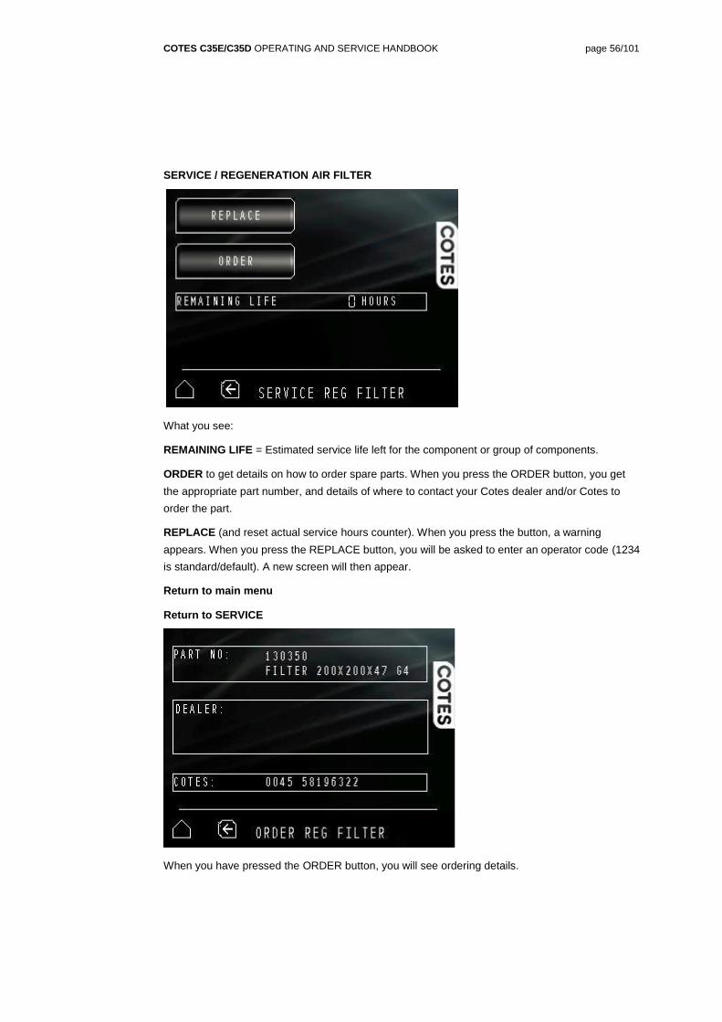
SERVICE / REGENERATION AIR FILTER
What you see:
REMAINING LIFE = Estimated service life left for the component or group of components.
ORDER to get details on how to order spare parts. When you press the ORDER button, you get
the appropriate part number, and details of where to contact your Cotes dealer and/or Cotes to
order the part.
REPLACE (and reset actual service hours counter). When you press the button, a warning
appears. When you press the REPLACE button, you will be asked to enter an operator code (1234
is standard/default). A new screen will then appear.
Return to main menu
Return to SERVICE
When you have pressed the ORDER button, you will see ordering details.
COTES C35E/C35D OPERATING AND SERVICE HANDBOOK page 57/101
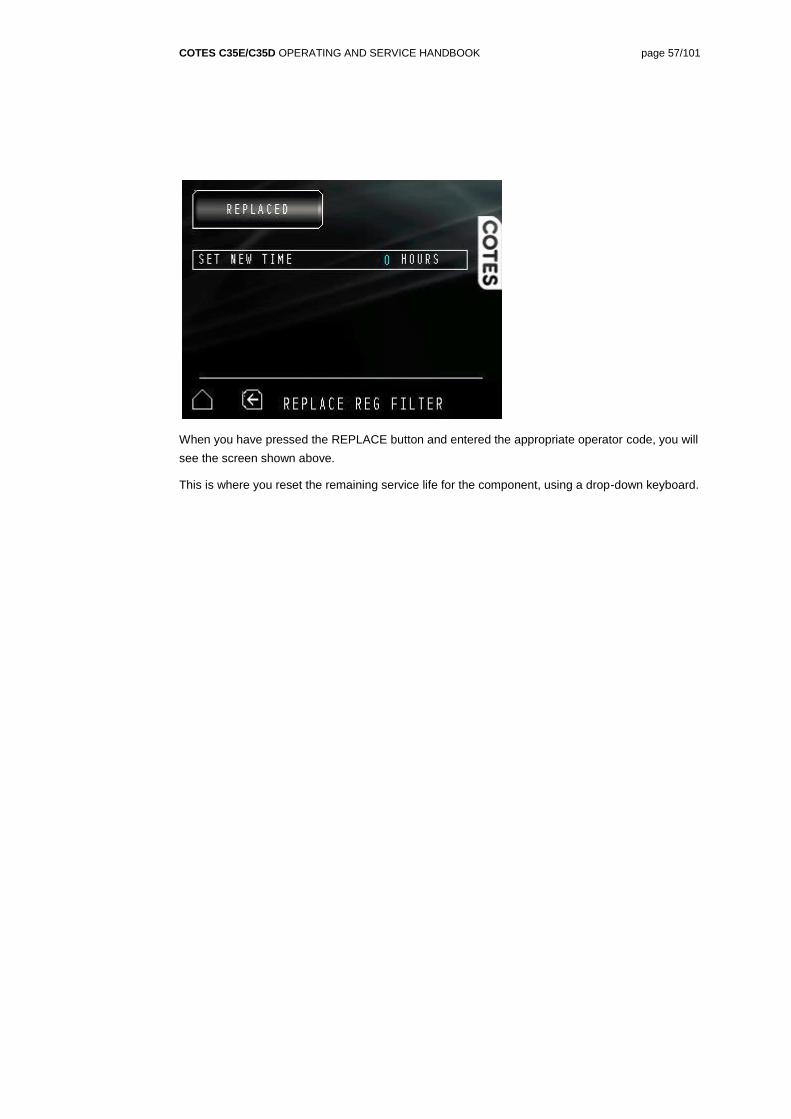
When you have pressed the REPLACE button and entered the appropriate operator code, you will
see the screen shown above.
This is where you reset the remaining service life for the component, using a drop-down keyboard.
COTES C35E/C35D OPERATING AND SERVICE HANDBOOK page 58/101
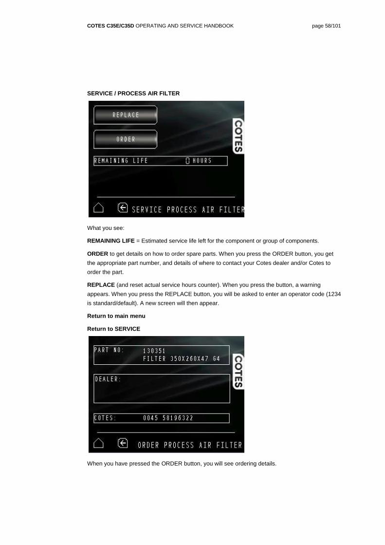
SERVICE / PROCESS AIR FILTER
What you see:
REMAINING LIFE = Estimated service life left for the component or group of components.
ORDER to get details on how to order spare parts. When you press the ORDER button, you get
the appropriate part number, and details of where to contact your Cotes dealer and/or Cotes to
order the part.
REPLACE (and reset actual service hours counter). When you press the button, a warning
appears. When you press the REPLACE button, you will be asked to enter an operator code (1234
is standard/default). A new screen will then appear.
Return to main menu
Return to SERVICE
When you have pressed the ORDER button, you will see ordering details.
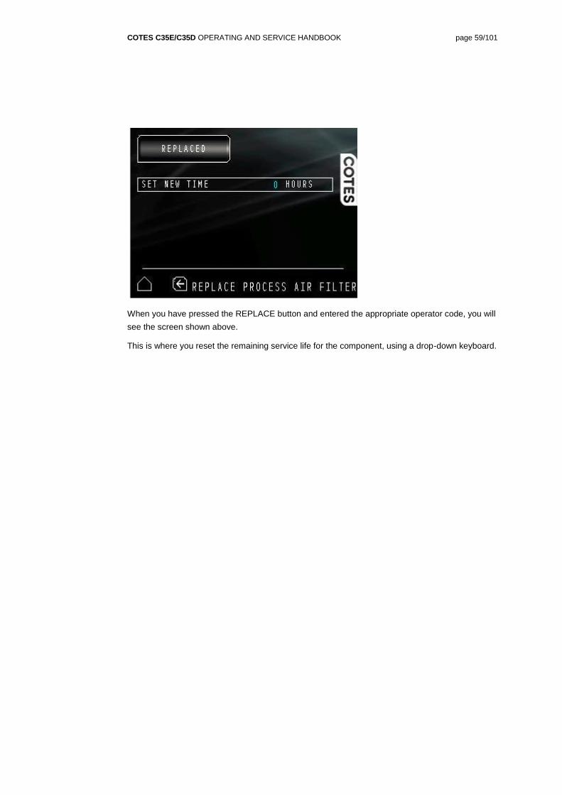
COTES C35E/C35D OPERATING AND SERVICE HANDBOOK page 59/101
When you have pressed the REPLACE button and entered the appropriate operator code, you will
see the screen shown above.
This is where you reset the remaining service life for the component, using a drop-down keyboard.
COTES C35E/C35D OPERATING AND SERVICE HANDBOOK page 60/101
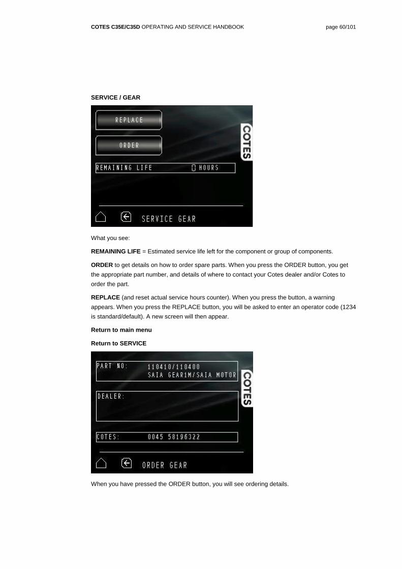
SERVICE / GEAR
What you see:
REMAINING LIFE = Estimated service life left for the component or group of components.
ORDER to get details on how to order spare parts. When you press the ORDER button, you get
the appropriate part number, and details of where to contact your Cotes dealer and/or Cotes to
order the part.
REPLACE (and reset actual service hours counter). When you press the button, a warning
appears. When you press the REPLACE button, you will be asked to enter an operator code (1234
is standard/default). A new screen will then appear.
Return to main menu
Return to SERVICE
When you have pressed the ORDER button, you will see ordering details.
COTES C35E/C35D OPERATING AND SERVICE HANDBOOK page 61/101
When you have pressed the REPLACE button and entered the appropriate operator code, you will
see the screen shown above.
This is where you reset the remaining service life for the component, using a drop-down keyboard.
COTES C35E/C35D OPERATING AND SERVICE HANDBOOK page 62/101
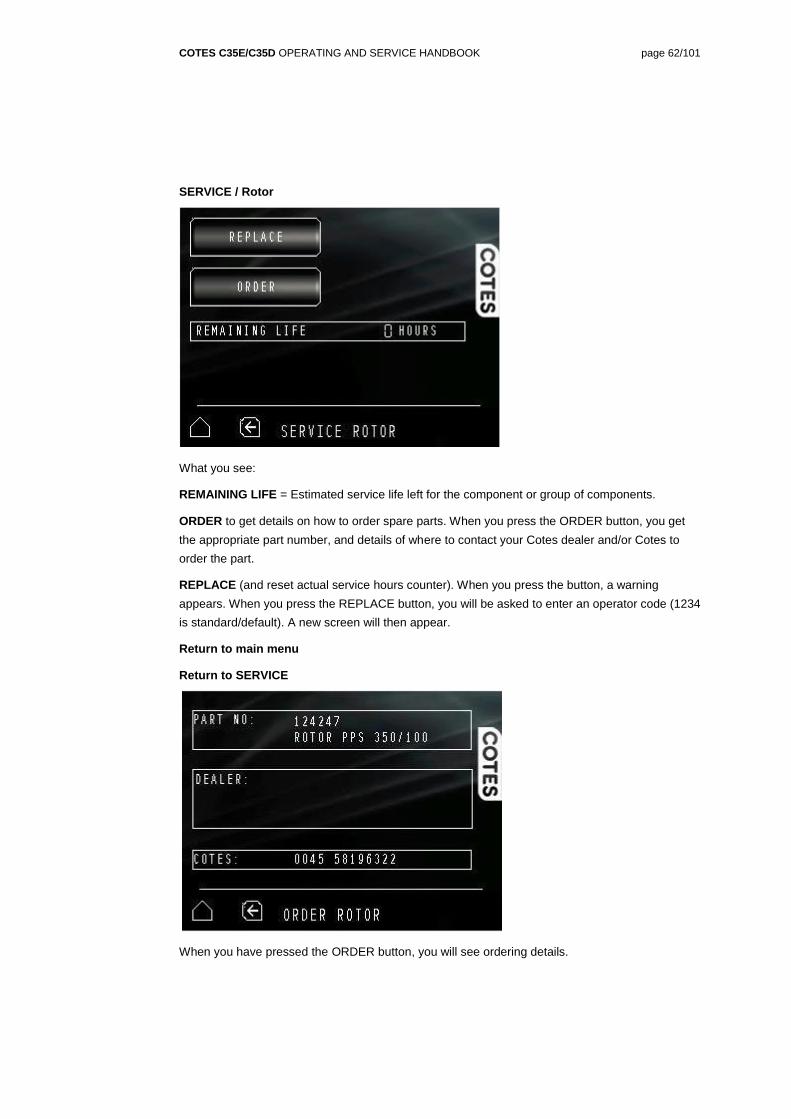
SERVICE / Rotor
What you see:
REMAINING LIFE = Estimated service life left for the component or group of components.
ORDER to get details on how to order spare parts. When you press the ORDER button, you get
the appropriate part number, and details of where to contact your Cotes dealer and/or Cotes to
order the part.
REPLACE (and reset actual service hours counter). When you press the button, a warning
appears. When you press the REPLACE button, you will be asked to enter an operator code (1234
is standard/default). A new screen will then appear.
Return to main menu
Return to SERVICE
When you have pressed the ORDER button, you will see ordering details.
COTES C35E/C35D OPERATING AND SERVICE HANDBOOK page 63/101
When you have pressed the REPLACE button and entered the appropriate operator code, you will
see the screen shown above.
This is where you reset the remaining service life for the component, using a drop-down keyboard.
COTES C35E/C35D OPERATING AND SERVICE HANDBOOK page 64/101
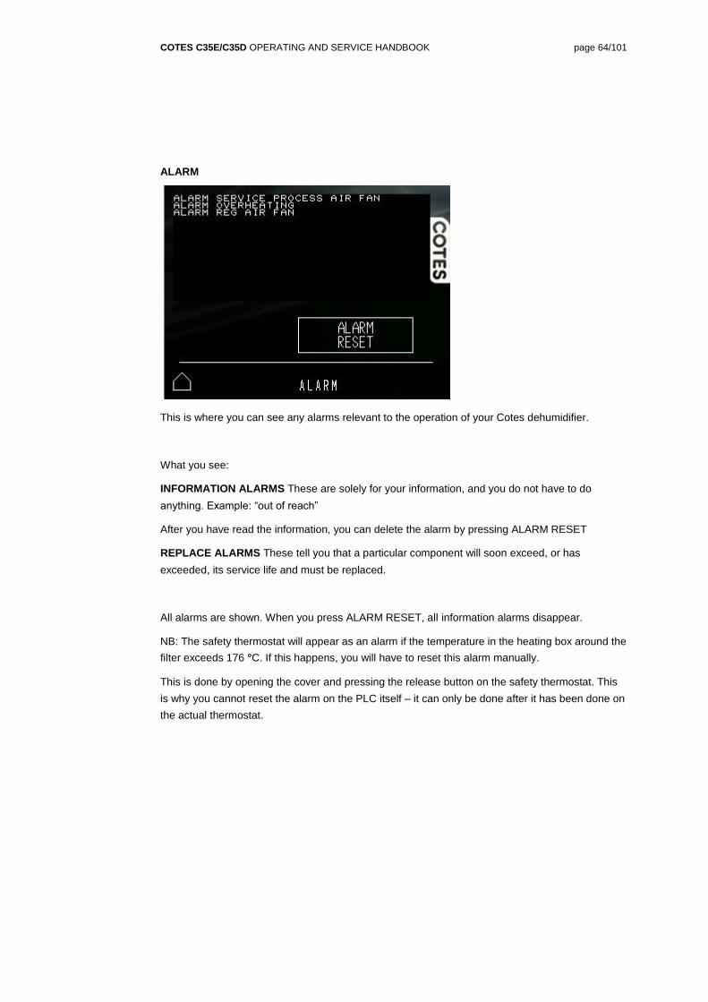
ALARM
This is where you can see any alarms relevant to the operation of your Cotes dehumidifier.
What you see:
INFORMATION ALARMS These are solely for your information, and you do not have to do
anything. Example: “out of reach”
After you have read the information, you can delete the alarm by pressing ALARM RESET
REPLACE ALARMS These tell you that a particular component will soon exceed, or has
exceeded, its service life and must be replaced.
All alarms are shown. When you press ALARM RESET, all information alarms disappear.
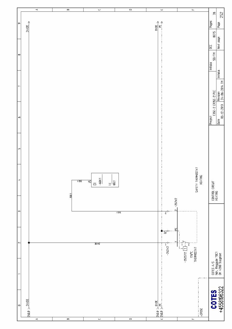
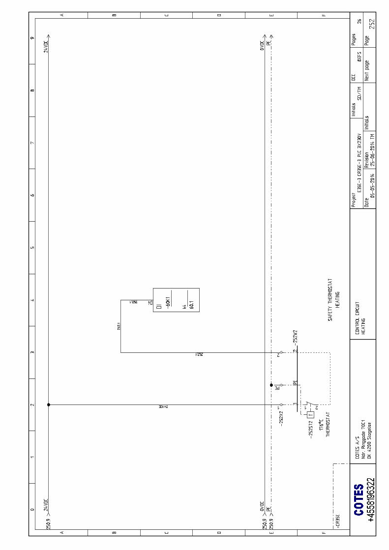
NB: The safety thermostat will appear as an alarm if the temperature in the heating box around the
filter exceeds 176 °C. If this happens, you will have to reset this alarm manually.
This is done by opening the cover and pressing the release button on the safety thermostat. This
is why you cannot reset the alarm on the PLC itself – it can only be done after it has been done on
the actual thermostat.
COTES C35E/C35D OPERATING AND SERVICE HANDBOOK page 65/101
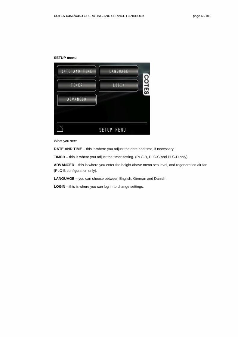
SETUP menu
What you see:
DATE AND TIME – this is where you adjust the date and time, if necessary.
TIMER – this is where you adjust the timer setting. (PLC-B, PLC-C and PLC-D only).
ADVANCED – this is where you enter the height above mean sea level, and regeneration air fan
(PLC-B configuration only).
LANGUAGE – you can choose between English, German and Danish.
LOGIN – this is where you can log in to change settings.
COTES C35E/C35D OPERATING AND SERVICE HANDBOOK page 66/101
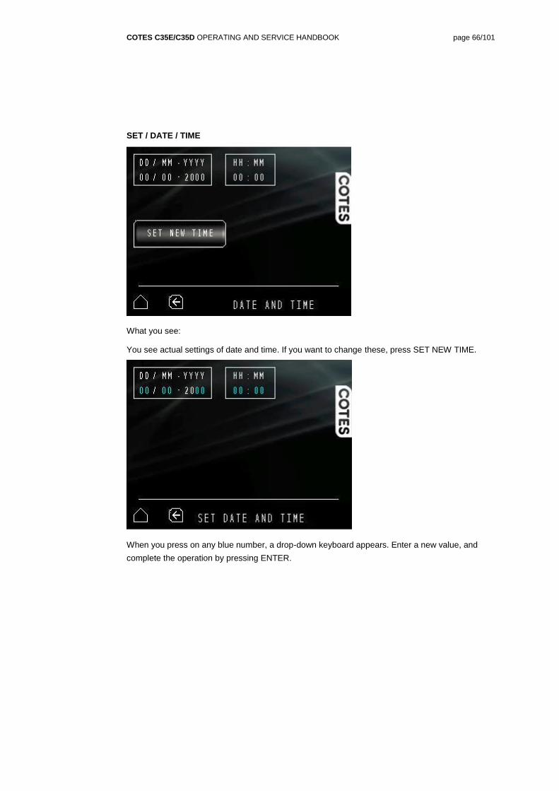
SET / DATE / TIME
What you see:
You see actual settings of date and time. If you want to change these, press SET NEW TIME.
When you press on any blue number, a drop-down keyboard appears. Enter a new value, and
complete the operation by pressing ENTER.
COTES C35E/C35D OPERATING AND SERVICE HANDBOOK page 67/101
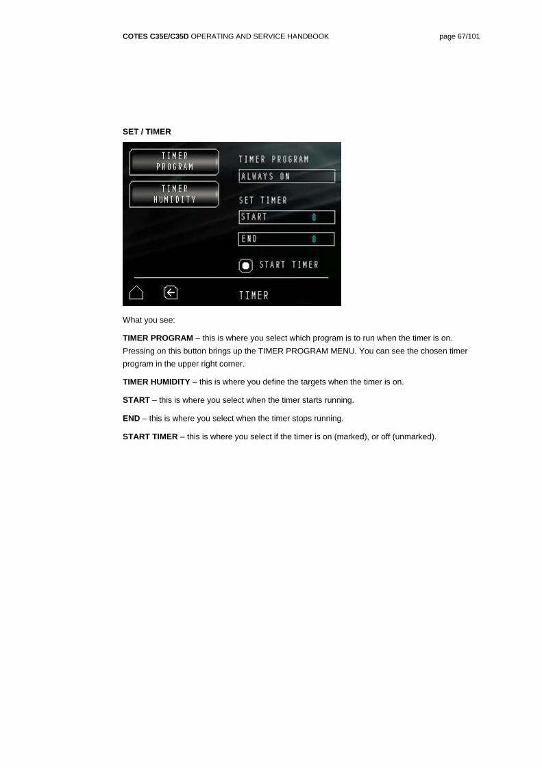
SET / TIMER
What you see:
TIMER PROGRAM – this is where you select which program is to run when the timer is on.
Pressing on this button brings up the TIMER PROGRAM MENU. You can see the chosen timer
program in the upper right corner.
TIMER HUMIDITY – this is where you define the targets when the timer is on.
START – this is where you select when the timer starts running.
END – this is where you select when the timer stops running.
START TIMER – this is where you select if the timer is on (marked), or off (unmarked).
COTES C35E/C35D OPERATING AND SERVICE HANDBOOK page 68/101
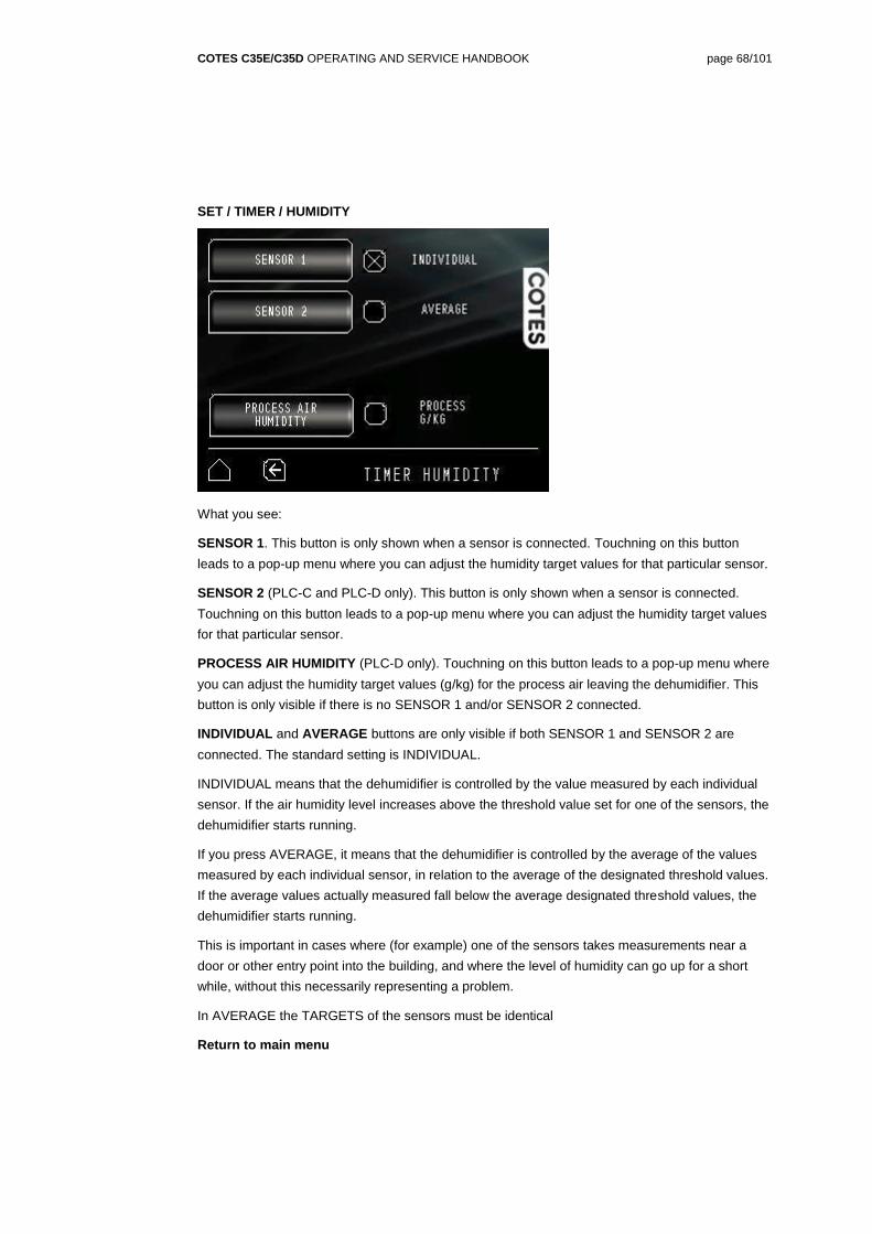
SET / TIMER / HUMIDITY
What you see:
SENSOR 1. This button is only shown when a sensor is connected. Touchning on this button
leads to a pop-up menu where you can adjust the humidity target values for that particular sensor.
SENSOR 2 (PLC-C and PLC-D only). This button is only shown when a sensor is connected.
Touchning on this button leads to a pop-up menu where you can adjust the humidity target values
for that particular sensor.
PROCESS AIR HUMIDITY (PLC-D only). Touchning on this button leads to a pop-up menu where
you can adjust the humidity target values (g/kg) for the process air leaving the dehumidifier. This
button is only visible if there is no SENSOR 1 and/or SENSOR 2 connected.
INDIVIDUAL and AVERAGE buttons are only visible if both SENSOR 1 and SENSOR 2 are
connected. The standard setting is INDIVIDUAL.
INDIVIDUAL means that the dehumidifier is controlled by the value measured by each individual
sensor. If the air humidity level increases above the threshold value set for one of the sensors, the
dehumidifier starts running.
If you press AVERAGE, it means that the dehumidifier is controlled by the average of the values
measured by each individual sensor, in relation to the average of the designated threshold values.
If the average values actually measured fall below the average designated threshold values, the
dehumidifier starts running.
This is important in cases where (for example) one of the sensors takes measurements near a
door or other entry point into the building, and where the level of humidity can go up for a short
while, without this necessarily representing a problem.
In AVERAGE the TARGETS of the sensors must be identical
Return to main menu
COTES C35E/C35D OPERATING AND SERVICE HANDBOOK page 69/101
SET / TIMER / HUMIDITY / SENSOR1
What you see:
Actual values measured by sensor 1 (measures both %RH and ˚C. PLC-B, PLC-C and PLC-D
also measures actual dew point temperature).
Controlling RELATIVE HUMIDITY with the dehumidifier. Pressing the RELATIVE HUMIDITY
checkbox makes the dehumidifier control relative humidity as measured by the sensor.
Target value can be changed by pressing the blue number. Then a keyboard shows up where
you can type in new value. Threshold values are defining the hysteresis for ON/OFF programme.
Further, the MIN value defines when the dehumidifier is turned off in ENERGY, QUIET and
CUSTOM programme (only for PLC-C and PLC-D). See page 71 for more information.
Threshold values (MIN and MAX) for target humidity can be changed the same way, by pressing
the blue numbers.
Controlling DEW POINT with the dehumidifier (PLC-B, PLC-C and PLC-D only). Pressing the
DEW POINT checkbox makes the dehumidifier control dew point as measured by the sensor.
Target value can be changed by pressing the blue number. Then a keyboard shows up where
you can type in a new value.
Threshold values (MIN and MAX) for target humidity can be changed the same way, by pressing
the blue numbers. Threshold values are defining the hysteresis for ON/OFF programme. Further,
the MIN value defines when the dehumidifier is turned off in ENERGY, QUIET and CUSTOM
programme (only for PLC-C and PLC-D). See page 71 for more information.
Controlling both RELATIVE HUMIDITY and DEW POINT with the dehumidifier (PLC-B, PLC-C
and PLC-D only). If required, you can control the dehumidifier on the basis of both %RH and dew
point measurements at the same time. In such cases, both checkboxes should be marked.
Return to main menu
Return to HUMIDITY menu
COTES C35E/C35D OPERATING AND SERVICE HANDBOOK page 70/101
SET / TIMER / HUMIDITY / SENSOR2
What you see:
Actual values measured by sensor 2 (measures both %RH and ˚C. PLC-B, PLC-C and PLC-D
also measure actual dew point temperature).)
Controlling RELATIVE HUMIDITY with the dehumidifier. Pressing the RELATIVE HUMIDITY
checkbox makes the dehumidifier control relative humidity as measured by the sensor.
Target value can be changed by pressing the blue number. Then a keyboard shows up where
you can type in a new value.
Threshold values (MIN and MAX) for target humidity can be changed the same way, by pressing
the blue numbers. Threshold values are defining the hysteresis for ON/OFF programme. Further,
the MIN value defines when the dehumidifier is turned off in ENERGY, QUIET and CUSTOM
programme (only for PLC-C and PLC-D). See page 71 for more information.
Controlling DEW POINT with the dehumidifier (PLC-B, PLC-C and PLC-D only). Pressing the
DEW POINT checkbox makes the dehumidifier control dew point as measured by the sensor.
Target value can be changed by pressing the blue number. Then a keyboard shows up where
you can type in a new value.
Threshold values (MIN and MAX) for target humidity can be changed the same way, by pressing
the blue numbers. Threshold values are defining the hysteresis for ON/OFF programme. Further,
the MIN value defines when the dehumidifier is turned off in ENERGY, QUIET and CUSTOM
programme (only for PLC-C and PLC-D). See page 71 for more information.
Controlling both RELATIVE HUMIDITY and DEW POINT with the dehumidifier (PLC-B, PLC-C
and PLC-D only). If required, you can control the dehumidifier on the basis of both %RH and dew
point measurements at the same time. In such cases, both checkboxes should be marked.
Return to main menu
Return to HUMIDITY menu
COTES C35E/C35D OPERATING AND SERVICE HANDBOOK page 71/101
SET / TIMER / PROGRAM
What you see:
Below only for dehumidifier in timer mode.
ALWAYS ON The dehumidifier is running at full power all the time.
ON/OFF The dehumidifier is controlled by an external sensor. When the values measured by this
sensor are below the threshold you have set, the dehumidifier is turned off. When the values
measured by this sensor are above the target you have set, the dehumidifier is turned on, and
running at full power. See more details of targets and threshold on page 69 and 70.
CAPACITY CONTROL (PLC-B only). The focus is on removing unwanted humidity, so the fans
are running at all times. The level of heat is adjusted to meet requirements. The dehumidifier does
not make adjustments in relation to threshold values.
ENERGY (PLC-C only). In addition to removing unwanted humidity, the focus here is on removing
such humidity, in a more energy-efficient manner. When turned on the speed of the rotor and the
level of heat are adjusted to meet requirements and to save energy.
The dehumidifier is turned off when the values measured by the sensor(s) are below the threshold
MIN value you have set. See page 69 and 70 for more details.
ENERGY (PLC-D only). The focus here is on removing unwanted humidity and keeping overall
energy consumption to a minimum. In PLC-D’s ENERGY programme, the flow of air, the level of
heat and the rotation of the humidity-absorbing rotor are all controlled by measurements made by
high-precision internal sensors.
The dehumidifier is turned off when the values measured by the sensor(s) are below the threshold
MIN value you have set. See page 69 and 70 for more details.
QUIET (PLC-C and PLC-D only). The focus here is on making sure the dehumidifier runs as
quietly as possible. The dehumidifier is only turned on then values measured by external sensor is
above the target you have set.
In this configuration, all the air flows are reduced as much as possible, in order to keep noise
levels to a minimum.
COTES C35E/C35D OPERATING AND SERVICE HANDBOOK page 72/101
The dehumidifier is turned off when the values measured by the sensor(s) are below the threshold
MIN value you have set. See page 69 and 70 for more details.
CUSTOM SETUP (PLC-C and PLC-D only). In this configuration, you can adjust all the values
individually, within predefined limits. See page 73 for more details.
The dehumidifier is turned off when the values measured by the sensor(s) are below the threshold
MIN value you have set. See page 69 and 70 for more details.
Return to main menu
COTES C35E/C35D OPERATING AND SERVICE HANDBOOK page 73/101
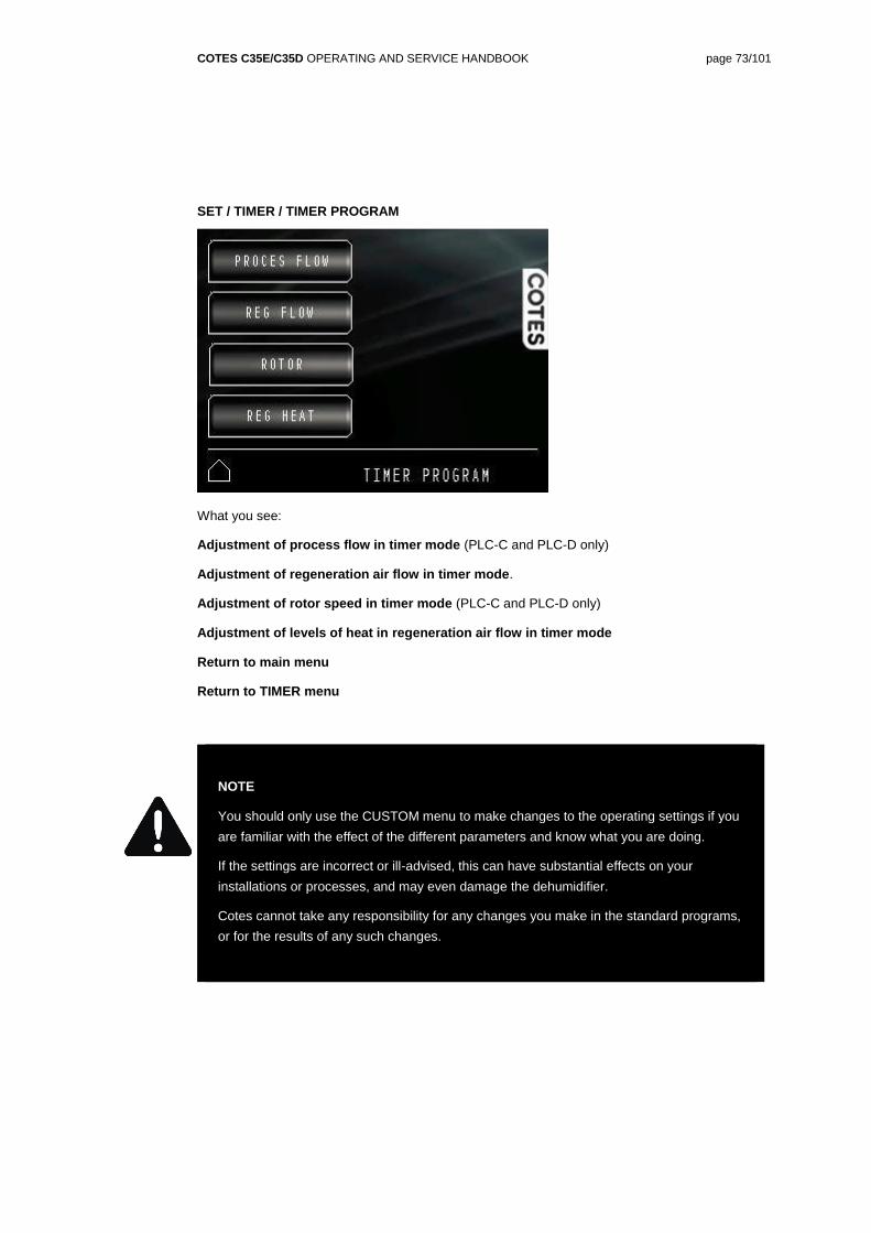
SET / TIMER / TIMER PROGRAM
What you see:
Adjustment of process flow in timer mode (PLC-C and PLC-D only)
Adjustment of regeneration air flow in timer mode.
Adjustment of rotor speed in timer mode (PLC-C and PLC-D only)
Adjustment of levels of heat in regeneration air flow in timer mode
Return to main menu
Return to TIMER menu
NOTE
You should only use the CUSTOM menu to make changes to the operating settings if you
are familiar with the effect of the different parameters and know what you are doing.
If the settings are incorrect or ill-advised, this can have substantial effects on your
installations or processes, and may even damage the dehumidifier.
Cotes cannot take any responsibility for any changes you make in the standard programs,
or for the results of any such changes.
COTES C35E/C35D OPERATING AND SERVICE HANDBOOK page 74/101
SET / TIMER / TIMER PROGRAM / CUSTOM / PROCESS FLOW
What you see:
% in relation to maximum fan speed (PLC-C and PLC-D only)
m3/hour (PLC-C and PLC-D only)
kg/hour (PLC-C and PLC-D only)
Return to main menu
To TIMER CUSTOM menu
The setting you have selected appears in blue.
The values in this setting remain constant while the dehumidifier is running, but the other values
can change.
You change the values by pressing on the blue number, and you change the function by pressing
anywhere else on the button.
The dehumidifier is turned off when the values measured by the sensor(s) are below the threshold
MIN value you have set. See page 69 and 70 for more details.
NOTE
You should only change the process air flow if you are familiar with the effect of the different
parameters and know what you are doing.
If the settings are incorrect or ill-advised, this can have substantial effects on your
installations or processes, and may even damage the dehumidifier.
Cotes cannot take any responsibility for any changes you make in the standard programs,
or for the results of any such changes.
COTES C35E/C35D OPERATING AND SERVICE HANDBOOK page 75/101
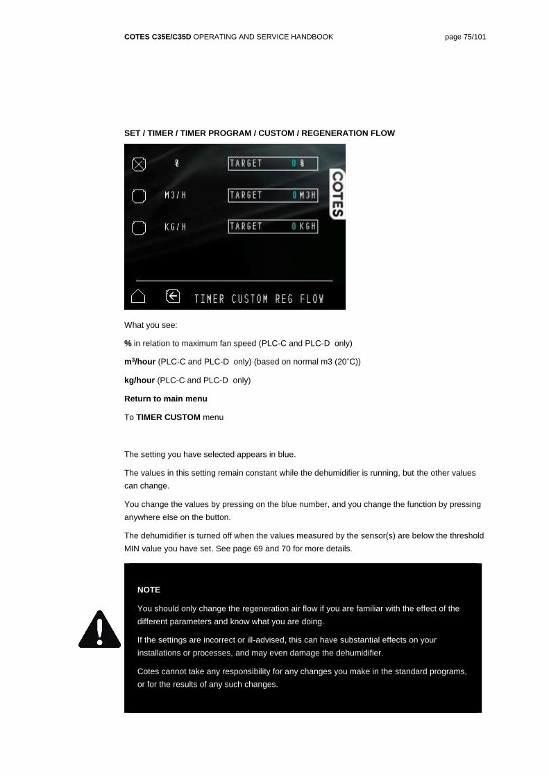
SET / TIMER / TIMER PROGRAM / CUSTOM / REGENERATION FLOW
What you see:
% in relation to maximum fan speed (PLC-C and PLC-D only)
m3/hour (PLC-C and PLC-D only) (based on normal m3 (20˚C))
kg/hour (PLC-C and PLC-D only)
Return to main menu
To TIMER CUSTOM menu
The setting you have selected appears in blue.
The values in this setting remain constant while the dehumidifier is running, but the other values
can change.
You change the values by pressing on the blue number, and you change the function by pressing
anywhere else on the button.
The dehumidifier is turned off when the values measured by the sensor(s) are below the threshold
MIN value you have set. See page 69 and 70 for more details.
NOTE
You should only change the regeneration air flow if you are familiar with the effect of the
different parameters and know what you are doing.
If the settings are incorrect or ill-advised, this can have substantial effects on your
installations or processes, and may even damage the dehumidifier.
Cotes cannot take any responsibility for any changes you make in the standard programs,
or for the results of any such changes.
COTES C35E/C35D OPERATING AND SERVICE HANDBOOK page 76/101
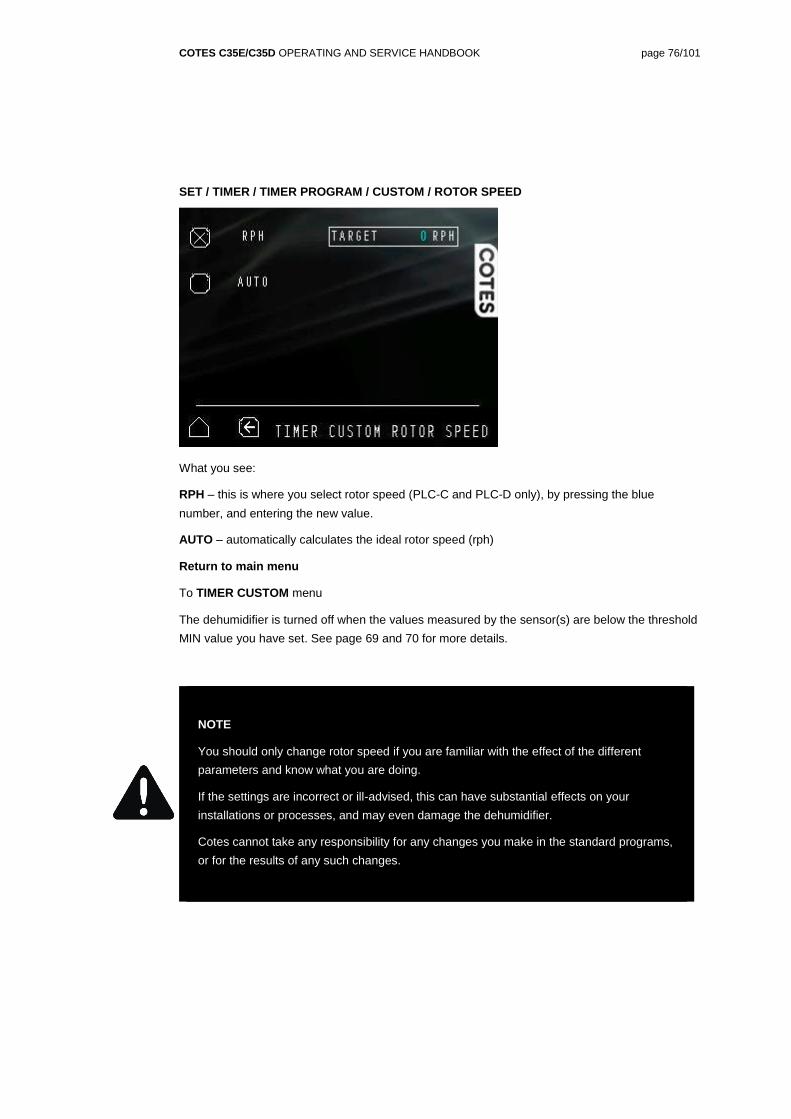
SET / TIMER / TIMER PROGRAM / CUSTOM / ROTOR SPEED
What you see:
RPH – this is where you select rotor speed (PLC-C and PLC-D only), by pressing the blue
number, and entering the new value.
AUTO – automatically calculates the ideal rotor speed (rph)
Return to main menu
To TIMER CUSTOM menu
The dehumidifier is turned off when the values measured by the sensor(s) are below the threshold
MIN value you have set. See page 69 and 70 for more details.
NOTE
You should only change rotor speed if you are familiar with the effect of the different
parameters and know what you are doing.
If the settings are incorrect or ill-advised, this can have substantial effects on your
installations or processes, and may even damage the dehumidifier.
Cotes cannot take any responsibility for any changes you make in the standard programs,
or for the results of any such changes.
COTES C35E/C35D OPERATING AND SERVICE HANDBOOK page 77/101
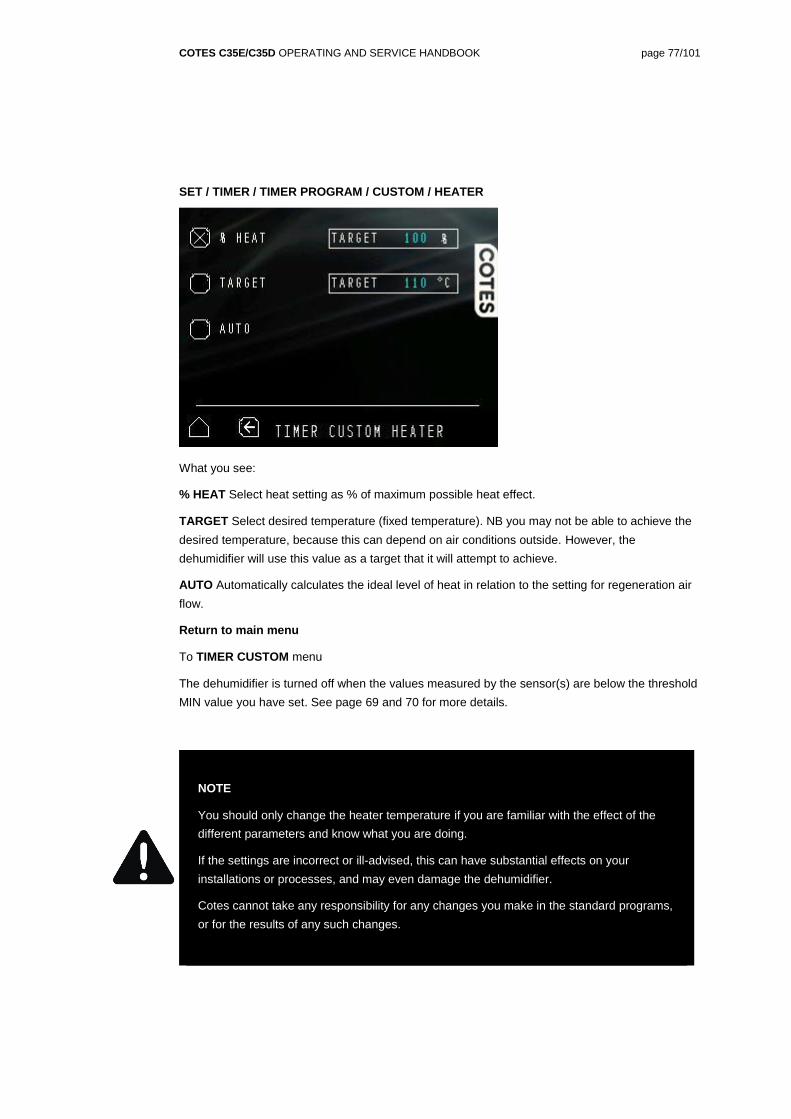
SET / TIMER / TIMER PROGRAM / CUSTOM / HEATER
What you see:
% HEAT Select heat setting as % of maximum possible heat effect.
TARGET Select desired temperature (fixed temperature). NB you may not be able to achieve the
desired temperature, because this can depend on air conditions outside. However, the
dehumidifier will use this value as a target that it will attempt to achieve.
AUTO Automatically calculates the ideal level of heat in relation to the setting for regeneration air
flow.
Return to main menu
To TIMER CUSTOM menu
The dehumidifier is turned off when the values measured by the sensor(s) are below the threshold
MIN value you have set. See page 69 and 70 for more details.
NOTE
You should only change the heater temperature if you are familiar with the effect of the
different parameters and know what you are doing.
If the settings are incorrect or ill-advised, this can have substantial effects on your
installations or processes, and may even damage the dehumidifier.
Cotes cannot take any responsibility for any changes you make in the standard programs,
or for the results of any such changes.
COTES C35E/C35D OPERATING AND SERVICE HANDBOOK page 78/101
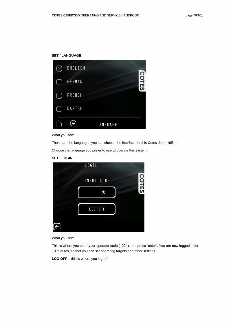
SET / LANGUAGE
What you see:
These are the languages you can choose the interface for this Cotes dehumidifier.
Choose the language you prefer to use to operate this system.
SET / LOGIN
What you see:
This is where you enter your operator code (1234), and press “enter”. You are now logged in for
10 minutes, so that you can set operating targets and other settings.
LOG OFF – this is where you log off.
COTES C35E/C35D OPERATING AND SERVICE HANDBOOK page 79/101
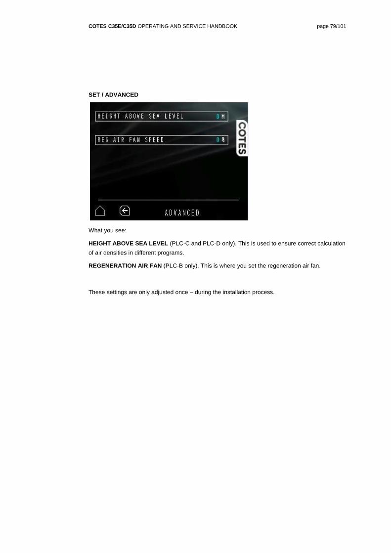
SET / ADVANCED
What you see:
HEIGHT ABOVE SEA LEVEL (PLC-C and PLC-D only). This is used to ensure correct calculation
of air densities in different programs.
REGENERATION AIR FAN (PLC-B only). This is where you set the regeneration air fan.
These settings are only adjusted once – during the installation process.
COTES C35E/C35D OPERATING AND SERVICE HANDBOOK page 80/101
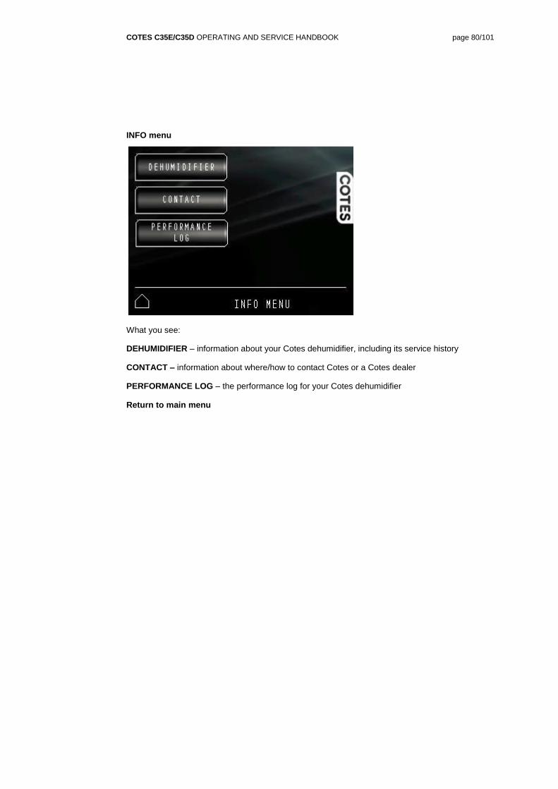
INFO menu
What you see:
DEHUMIDIFIER – information about your Cotes dehumidifier, including its service history
CONTACT – information about where/how to contact Cotes or a Cotes dealer
PERFORMANCE LOG – the performance log for your Cotes dehumidifier
Return to main menu
COTES C35E/C35D OPERATING AND SERVICE HANDBOOK page 81/101
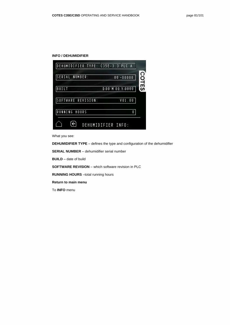
INFO / DEHUMIDIFIER
What you see:
DEHUMIDIFIER TYPE – defines the type and configuration of the dehumidifier
SERIAL NUMBER – dehumidifier serial number
BUILD – date of build
SOFTWARE REVISION – which software revision in PLC
RUNNING HOURS –total running hours
Return to main menu
To INFO menu
COTES C35E/C35D OPERATING AND SERVICE HANDBOOK page 82/101
INFO / SERVICE HISTORY
What you see:
SERVICE HISTORY – List of service performed on dehumidifier
Return to main menu
To INFO menu
COTES C35E/C35D OPERATING AND SERVICE HANDBOOK page 83/101
INFO / CONTACT
What you see:
INSTALLED – date of installation
CUSTOMER – who gets benefit of the dehumidifier
DEALER – who has sold the dehumidifier
CONTACT – how to get in contact with Cotes
Return to main menu
To INFO menu
COTES C35E/C35D OPERATING AND SERVICE HANDBOOK page 84/101
INFO / PERFORMANCE LOG
What you see:
TARGET RH – your target for relative humidity (%) (blue curve)
ACT RH – the actual relative humidity measured (white curve)
ACT T – the actual temperature measured (red curve)
DISP – see historical values
PREV – turning to previous screen
FWD – turning to next screen
ZOOM IN – zooming in
ZOOM OUT – zooming out
Return to main menu
To INFO menu
COTES C35E/C35D OPERATING AND SERVICE HANDBOOK page 85/101
SECTION 6 / SERVICE AND REPAIR
HOW TO SERVICE AND REPAIR THIS DEHUMIDIFIER
Service and maintenance work on this dehumidifier
Cotes designs its dehumidifier units so that they are as robust as possible, and only need a minimum of service and maintenance.
None of the components require lubrication or adjustment.
The only maintenance work you need to do is listed below.
Once a month
Check or replace the filters for incoming air and regeneration air. For PLC-B, PLC-C and PLC-D configurations, the filter guard will automatically provide a warning if there are problems.
Check that the fans are operating (by listening to check whether they are turning).
Once a year
We also recommend the following annual checks.
Check the service indication menu in the PLC. Are the working hours of any component inside near their time-to-change limit? If so, replace. See time-to-change limits below:
o Process air filter. Depends on the working environment. Specified for 8,700 hours under normal conditions.
o Regeneration air filter. Depends on the working environment. Specified for 8,700 hours under normal conditions.
o Air filter for electronics box. Depends on the working environment. Specified for 8,700 hours under normal conditions.
o Process air fan: 40,000 hours
o Regeneration air fan: 30,000 hours
o Motor and gear for rotor: 30,000 hours
o Heaters: 40,000 hours
o Filter guard (if installed): 40,000 hours
o Manometer (if installed): 40,000 hours
o Rotor, including gaskets: 60,000 hours
o Electrical board including PLC: 60,000 hours
External humidity sensor should be calibrated or replaced (with recycled instruments)
Internal humidity sensor (only PLC-D) should be replaced (with recycled instruments)
Check the wear on the rotor gaskets, especially the gasket placed on the circumference of the rotor. The red side of the gasket is made of Teflon®, and this coating must be intact over its entire surface.
Check the inside of the cabinet for any signs of dirt or corrosion. Check that the drive belt for the rotor is still tight and that no parts of it are too worn or close to the breaking point.
Check that the insulation on all electrical cables is intact, with no mechanical or heat
COTES C35E/C35D OPERATING AND SERVICE HANDBOOK page 86/101
damage.
Check that the insulation on the electric heater(s) is intact.
Check that all cables inside the electronics box are properly attached, all miniature circuit breakers (MCBs) are switched on and all components are intact.
Test that all electric components are working as intended – for example by following the instructions in the “Commissioning” section of this handbook.
Service/repair work on this dehumidifier
Safety instructions
Before opening the dehumidifier, make sure that the electric current is switched off at the mains before you open the electronics box cover or the covers for the electric heater, process air fan and rotor.
The QS1 safety switch should also be switched off.
You should never just turn off the power to the dehumidifier while it is running. The correct procedure is to press STOP, after which the machine runs a cooling cycle before the regeneration air fan stops. Turning the dehumidifier off properly prevents any over-heating.
WARNING
Make sure that electric current is switched off at the mains before you open the electronics
box cover or the covers for the electric heater, process air fan and rotor
The QS1 safety switch should also be switched off.
COTES C35E/C35D OPERATING AND SERVICE HANDBOOK page 87/101
Easy access for quick service
The electrical switchboard (contacts, fuse breakers, thermal relays, etc.) is placed in the
electronics box in the top of the dehumidifier cabinet, directly under the top cover, to make them
easy to get to.
All other electrical components (fan motors, gear motor, heating elements, etc.) are easy to
access when the service doors for these parts are opened.
Connecting 230V motors
All C35E/C35D dehumidifiers are fitted with 230VAC electric motors. This means it doesn’t matter how the plus/minus cables are connected.
COTES C35E/C35D OPERATING AND SERVICE HANDBOOK page 88/101
Replacing filters
Process air filter; 130351
Regeneration air filter; 130350
(Except if special filters are specified).
The following is standard procedure for replacing the filters;
Open front door
Loosen the finger screws on the filter doors
Replace the filters
COTES C35E/C35D OPERATING AND SERVICE HANDBOOK page 89/101
Replacing fans
Large process air fan: RH25C; 801667
Small process air fan: RH22V; 801668
Regeneration air fan: RH22V; 801668
The following is standard procedure for replacing the process air fan;
Remove top cover
Disconnect cables for process air fan
Remove the screws on the fan bracket
Remove the screws on the fan
Replace the process air fan
The following is standard procedure for replacing the regeneration air fan:
Disconnect cables for regeneration air fan
Dismount screw clamp fastened to the regeneration air fan box
Remove the regeneration air fan box
Insert a replacement regeneration air fan box, or remove the screws on the regeneration air fan box and replace the regeneration air fan
COTES C35E/C35D OPERATING AND SERVICE HANDBOOK page 90/101
Replacing PLC
PLC; 140620
The following is standard procedure for replacing the PLC unit.
- Remove the top cover
- Disconnect cables for the PLC
- Remove the screws for the PLC bracket
- Replace the PLC
COTES C35E/C35D OPERATING AND SERVICE HANDBOOK page 91/101
Replacing electrical board
400V electrical board; 619149
230V electrical board; 619199
The following is standard procedure for replacing an electrical board
Open the top cover
Disconnect all cables and sensors connected to the electrical board
Remove the screws fastening the electrical board to the cabinet
Replace the electrical board
COTES C35E/C35D OPERATING AND SERVICE HANDBOOK page 92/101
Replacing gear motor
Remove the drive belt from the pulley, then remove the gear motor after disconnecting all
electrical connections. You should then fit a replacement gear motor.
When re-starting up the unit, check that the rotor is moving. If not, swap the two cables on the
motor as described above.
COTES C35E/C35D OPERATING AND SERVICE HANDBOOK page 93/101
Replacing electric heaters
All electric heaters are mounted in the front of the heater section of the dehumidifier.
To replace these units, disconnect the wiring and unscrew the plate. You can then withdraw the
plate and heaters from the heating section.
COTES C35E/C35D OPERATING AND SERVICE HANDBOOK page 94/101
Replacing rotor, rotor gaskets and shaft
You do not need to remove the rotor to replace the rotor gaskets. You simply place the new gasket
on the rotor and fix it in place with the three-part expansion ring. You then turn the rotor, which
presses the gasket against the departing plates until only half of the gasket is on the rotor. The
expansion ring then fastens.
The following is standard procedure for replacing rotor gaskets.
Open door at the front of the cabinet
Remove the drive belt from the pulley
Remove the rotor gaskets
Mount new rotor gaskets
You can remove the rotor and mount new gaskets on it, but it is much easier to mount new gaskets without removing the rotor.
The following is standard procedure for replacing the rotor.
Open door at the front of the cabinet
Remove the drive belt from the pulley
Remove the rotor gaskets
Remove the screws for the rotor shaft
Remove the screws for the lower divider and spacers in-between the dividers
Carefully slide out the rotor (including the Teflon® disc and rotor shaft) before the rotor shaft can
be dismounted at the front.
COTES C35E/C35D OPERATING AND SERVICE HANDBOOK page 95/101
Troubleshooting
Problem Cause Action
The unit (or parts of it) will not
start after a power surge/an
electrical short circuit
One or more fuse breakers
have been triggered
Turn all fuse breakers on
The air is not as dry as
expected
The rotor is not turning
The regeneration air
temperature is lower than
expected
The regeneration air flow is
too low
If the drive belt is intact,
change the gear motor
Check that the regeneration
air flow is not too high
Check that all heating
elements are functioning
Check that the regeneration
air filter is not clogged
The regeneration air
temperature has large
variations
The regeneration air flow is
too low
Check that the regeneration
air filter is not clogged
If you have any queries or questions, please contact your Cotes dealer.
COTES C35E/C35D OPERATING AND SERVICE HANDBOOK page 96/101
SECTION 7 / FORMALITIES AND GENERAL/LEGAL INFO
WARRANTIES
Warranty conditions
The Cotes factory warranty is only valid if a documented programme of service and preventive
maintenance has been carried out.
Maintenance must have been carried out at intervals of six months or less. Documentation for this
must be in the form of a written log/journal, with attested entries.
All spare parts must have been purchased from Cotes or an authorised Cotes dealer.
COTES C35E/C35D OPERATING AND SERVICE HANDBOOK page 97/101
LEGAL NOTICES
Terms
The information contained in this publication and the products and equipment described herein are
subject to change at any time without prior notice.
Cotes A/S has no obligation to inform buyers of the products and equipment of such subsequent
changes.
This publication may contain misprints. Cotes A/S is not liable for errors or omissions in this
publication or for incidental or consequential damages in connection with the furnishing of or the
use of this publication.
Cotes A/S is not liable for any loss or damages, including consequential damages caused by
disregard of any advice or warnings in relation to safety in this publication.
This publication cannot be deemed to contain any express or implied warranties of any kind
concerning the construction or the suitability of the products described or the fitness of the
products for any particular purpose.
This publication is subject to the provisions and requirements laid down in Danish law.
Copyright
All copyright to this publication belongs to Cotes A/S.
All rights reserved. You are not allowed to photocopy, reproduce, adapt, modify, translate, display
or transfer any part of this publication to any other media, without explicit prior written permission
from Cotes A/S.
COTES C35E/C35D OPERATING AND SERVICE HANDBOOK page 98/101