25
A Sun Microsystems, Inc. Business

Counter ow Pipeline Processor Architecture
Robert F. SproullIvan E. Sutherland
Sun Microsystems Laboratories, Inc.
Charles E. MolnarInstitute for Biomedical Computing
Washington University
SMLI TR-94-25 April 1994
Abstract:
The counter ow pipeline processor architecture (cfpp) is a proposal for a family of micro-
architectures for risc processors. The architecture derives its name from its fundamental
feature, namely that instructions and results ow in opposite directions within a pipeline and
interact as they pass. The architecture seeks geometric regularity in processor chip layout,
purely local control to avoid performance limitations of complex global pipeline stall signals,
and simplicity that might lead to provably correct processor designs. Moreover, cfpp designs
allow asynchronous implementations, in contrast to conventional pipeline designs where the
synchronization required for operand forwarding makes asynchronous designs unattractive.
This paper presents the cfpp architecture and a proposal for an asynchronous implementation.
Detailed performance simulations of a complete processor design are not yet available.
Keywords: processor design, risc architecture, micropipelines, fifo, asynchronous systems
CR categories: B.2.1, B.6.1, C.1.0
A Sun Microsystems, Inc. Business
M/S 29-01
2550 Garcia Ave.
Mountain View, CA 94043
email addresses:

c Copyright 1994 Institute of Electrical and Electronics Engineers, Inc. Reprinted by permission. A
version of this paper will appear in IEEE Design and Test of Computers. The SMLI Technical Report
Series is published by Sun Microsystems Laboratories, Inc. Printed in U.S.A.
No part of this work covered by copyright hereon may be reproduced in any form or by any means
graphic, electronic, or mechanical, including photocopying, recording, taping, or storage in an informa-
tion retrieval system, without the prior written permission of the copyright owner.
TRADEMARKS
Sun, Sun Microsystems, and the Sun logo are trademarks or registered trademarks of Sun Microsystems,
Inc. UNIX and OPEN LOOK are registered trademarks of Unix System Laboratories, Inc. All SPARC
trademarks, including the SCD Compliant logo, are trademarks or registered trademarks of SPARC
International, Inc. SPARCstation, SPARCserver, SPARCengine, SPARCworks, and SPARCompiler
are licensed exclusively to Sun Microsystems, Inc. All other product names mentioned herein are the
trademarks of their respective owners.
Counter ow Pipeline Processor Architecture
Robert F. Sproull
Ivan E. Sutherland
Sun Microsystems Laboratories, Inc.
Mountain View, CA 94043
Charles E. MolnarInstitute for Biomedical Computing
Washington University
St. Louis, MO 63110
1 Introduction
The Counter ow Pipeline Processor (cfpp) architecture is a proposal for a simple and regular
structure for processor pipelines. It handles in a uniform way a number of features that
add complexity to conventional designs, including operand forwarding, register renaming, and
pipeline ushing following branches and traps. A cfpp uses a bi-directional pipeline|in which
instructions ow and results counter ow|to move partially-executed instructions and results
in a regular way, subject to a few pipeline rules that guarantee correct operation.
The cfpp structure has a number of properties that promise advantages:
� Local Control. Only local information is required to decide whether an item in the cfpp
pipeline should advance. There is no need to compute global \pipeline stall" signals and
then distribute them to all pipe stages. The complexity of such a global stall computation
and the time required to compute and distribute the signal are major headaches in current
processor designs.
� Regular Structure. The cfpp structure is very regular, which provides hope that it can
be laid out on silicon in a simple, regular way. The simplicity and regularity should also
help in devising correctness proofs.
� Local Communication. Pipeline stages communicate primarily with their nearest neigh-
bors, allowing short communication paths that can be very fast.
� Modular Structure. The uniform communication behavior of pipeline stages admits vari-
ants that di�er in the detailed design of individual stages or in the ordering of stages
in the pipeline. For example, one design may call for a single alu, another for separate
adder/subtractor and multiplier units; yet both have the same overall pipeline structure.
� Simplicity. Finally, the overall simplicity of the structure may mean that cfpp processors
are easier to design than their conventional counterparts, which might make them very
attractive.
The performance of cfpp designs is not known. The local nature of most communications
and control should permit very fast operation. On the other hand, cfpp designs may introduce
performance-limiting delays, such as the time between instruction issue and acquisition of all
required operands. We have not yet simulated enough cfpp variants to understand the limits
to achievable performance.
1
Program counter andinstruction fetch
Res
ults
flow
dow
n
Stage 2
Stage 1
Stage 0
Register file
Inst
ruct
ions
flow
up
Instruction Results
Instruction Results
Instruction Results
Stage R
Stage I
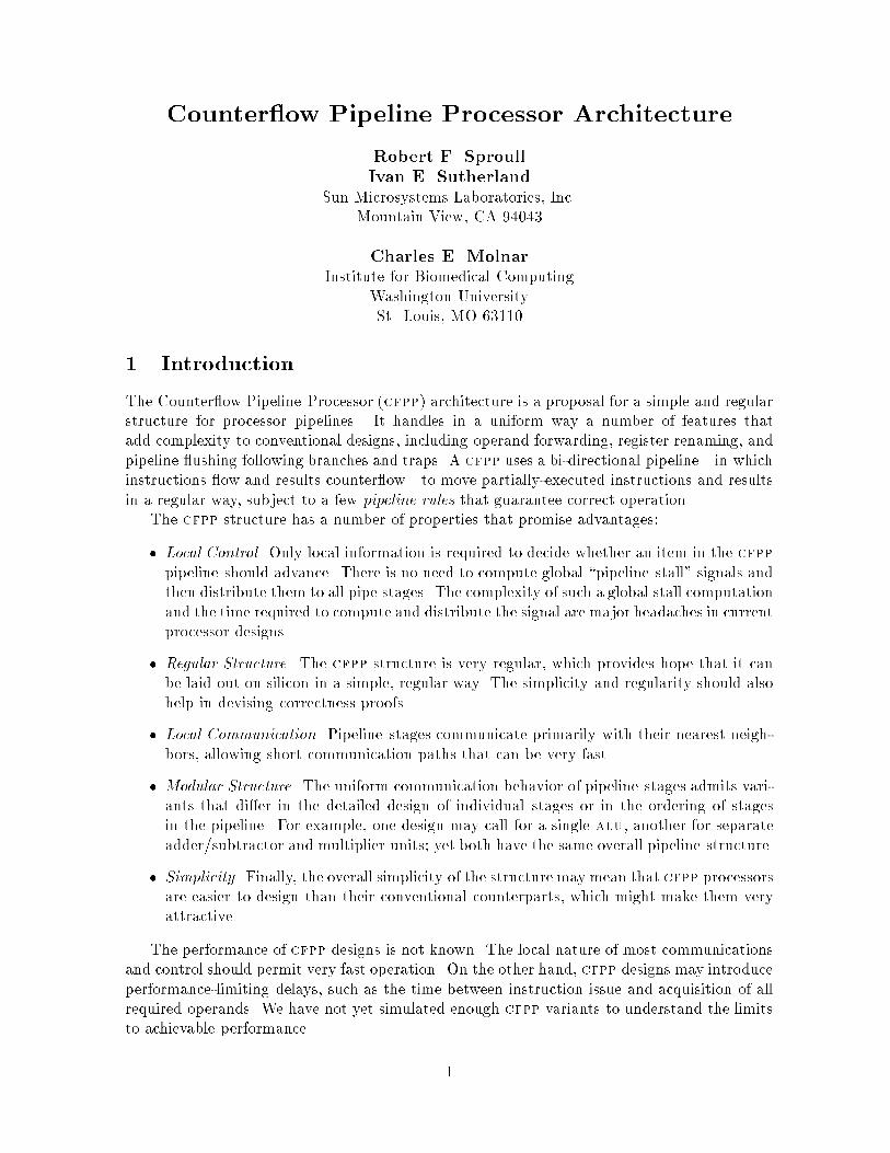
Figure 1: A simpli�ed counter ow pipeline processor.
2 Basic Structure
In a cfpp, a relatively long pipeline connects an instruction fetch unit at the bottom with
a register �le at the top (see Figure 1). We think of instructions owing up through this
instruction pipeline so that the sequence of instructions in the pipeline resembles a listing of
that section of code. Earlier instructions are above later ones and remain so because the design
forbids instructions to pass one another. Instructions move up the pipe as far and as fast as
they can, stalling only when the pipeline stage immediately above cannot yet accept a new
instruction or when the instruction reaches the last pipeline stage that is equipped to execute
it. Above a stalled instruction, a gap of arbitrary size may open in the pipeline; not every
stage needs to be \full" with an instruction.
Each instruction carries with it bindings for its source operands and its destination(s). Each
binding associates a data value with a register name; it consists of a register name, a data
value, and a validity bit to indicate whether the association is valid. The pipeline illustrated
in Figure 1 shows three bindings with each instruction, e.g., two sources and one destination.
When an instruction is executed, new data is placed into the data values of the destination
bindings, which are then marked valid. When the instruction reaches the top of the pipeline,
the data values recorded in destination bindings are written into the corresponding locations in
2

Instruction Latch Result Latch
=?
=?
=?
=?
=?
=?
Garnersource bindings
Update result bindings
Op Result 1 Result 2DestinationSource 2Source 1
Binding
value
validity bitregister name
Key:
Figure 2: Instruction and result bindings, together with logic for implementing the pipeline
rules.
the register �le. Until this �nal record is made in the register �le, instructions are considered
speculative and may be cancelled if required by a trap or branch.
Whenever an instruction is executed, the outputs are used in two ways. First, they are
entered in the instruction's destination bindings and are eventually retired into the register �le
as described above. Second, each destination binding is inserted into the downward- owing
results pipeline so that it may be observed by subsequent instructions. In Figure 1, each
stage of the results pipeline accommodates two bindings. Any later instruction that requires a
source binding whose register name matches the register name of a result binding will garner
the value by copying and retaining the value in the binding in the instruction pipe. The results
pipeline provides the function that in other designs is called \bypassing" or \forwarding" [6],
and does so in a way that is uniform for all stages.
Result bindings owing down may be modi�ed by a subsequent instruction. Each stage
must detect matches between instruction and result bindings, i.e., cases when the register
name in an instruction binding matches the register name in a result binding (see Figure 2).
An instruction that has already executed and has a destination binding that matches a result
binding must copy the value from the destination binding into the result binding. In this way,
later instructions will garner the most recent binding for any register. A di�erent situation
arises when the instruction has yet to execute; in this case, any result binding that matches
a destination binding in the instruction is killed from the result pipeline, because the binding
will not be valid for still later instructions. Thus, a particular result binding typically passes
only a short span of instructions: the section after the instruction that computes the value and
up to the next instruction that overwrites that value. These result-modi�cation rules insure
that any result that meets an instruction in the counter ow pipeline holds bindings that are
3

correct for that instruction. Note that several di�erent bindings for a register may be in transit
in di�erent parts of the pipeline at the same time. Such multiple result bindings serve the
same function as \register renaming" in other designs.
The register �le is also a source of operands for instructions; for this reason, the register
�le is the principal source of bindings inserted into the results pipe. There are many policies
that might be appropriate for determining which register values to fetch and send down the
pipe. For example, registers could be fetched at random. A preferable policy is to send down
the results pipe bindings that are known to match sources of instructions in the pipe; these
register values will be garnered by the relevant instructions and thus enable the instructions
to execute. In one implementation of this policy, the instruction-decoding stage sends source
register addresses to the register �le, which fetches register values and sends corresponding
bindings down the results pipe. Note that the register-fetching policy will a�ect performance,
even leading to deadlock if the policy prevents some instruction from ever receiving a value
for one of its sources, but no policy leads to erroneous computations.
To insure correct operation, the cfpp must detect matching bindings in each result owing
down with each instruction owing up. Each result must meet every subsequent instruction in
some pipeline stage, where the comparison is done. Thus, we must prevent adjacent pipeline
stages from swapping an instruction and result \at the same time," which would prevent
detecting matches. The interface between stages may either pass an instruction up or a result
down, but never both. In an asynchronous implementation, an arbiter between each pair of
stages enforces this communication protocol.
3 Pipeline Rules
The correctness of counter ow pipeline operation depends on a set of pipeline rules that each
stage must obey. These rules, which have been introduced above, are stated explicitly in this
section. The rules will be extended in our later discussion of traps and conditional branches.
The pipeline rules make frequent reference to bindings: source bindings and destination
bindings are held in instructions as they ow up the instruction pipeline, while result bindings
ow down the results pipeline. Each binding is speci�ed by a register name, a validity bit, and
a value, as shown in Figure 2. The validity bit indicates whether the association of register
name and value is valid. Register names embrace the general registers found in most risc
architectures, as well as other processor state such as a condition code register.
The �rst few pipeline rules concern instructions:
P0: No overtaking. Instructions must stay in program order in the instruction pipeline.
P1: Execution. If all of the source bindings for an instruction are valid, and if the instruction
is held in a stage that contains suitable computing logic, the instruction may execute.
When an instruction completes execution, its destination bindings(s) are marked valid
and value(s) are �lled in.
P2: Insert result. When an instruction completes execution, one or more copies of each of
its destination bindings is inserted into the results pipeline.
P3: Stall for operands. An un-executed instruction may not pass beyond the last stage of
the pipeline capable of executing it. In particular, an instruction cannot be retired into
the register �le until it has executed.
4

The following are matching rules that apply when an instruction and result are present in the
same pipe stage and have matching bindings (see Figure 2):
M0: Garner instruction operands. If a valid result binding matches an invalid source
binding, copy the result value to the source value and mark the source valid.
M1: Kill results. If an invalid destination binding matches a valid result binding, mark the
result binding invalid.
M2: Update results. If a valid destination binding matches a result binding, copy the
destination value into the result value and mark the result valid.
4 An Example
The operation of the counter ow pipeline subject to the pipeline rules can be illustrated with
a simple example. Let us posit a �ve-stage pipeline (Figure 1). The �rst stage (I) contains a
program counter, fetches instructions, and sends the instructions up the instruction pipeline.
It also sends source register addresses to the register �le. The next stages, numbered 2, 1, and
0, are identical; each one contains an alu capable of executing an integer instruction. The
�nal stage (R) is the register �le, containing registers named A, B, C, and D. The notation
A[] denotes a source, destination or result binding with register name A and an invalid value;
A[14] denotes a valid value of 14 �lled in.
Let us illustrate the operation of the pipeline using the following instruction sequence, in
which PC represents the program counter:
PC = 101 A := B + C
PC = 102 B := A +B
PC = 103 D := C � 1
The operation of the pipeline is illustrated using a series of snapshots, such as the one
presented below. Two columns show what is held in the instruction and result registers of
each pipeline stage; we assume that each stage can hold two result bindings at once. In order
to help anticipate the changes from one snapshot to another, upward- and downward-pointing
arrows indicate respectively that the instruction in the stage will move up in the next snapshot
or the result will move down. Bear in mind that many other execution histories are possible
because of di�erences in the timing of executions and the movement of instructions and results
through the pipeline.
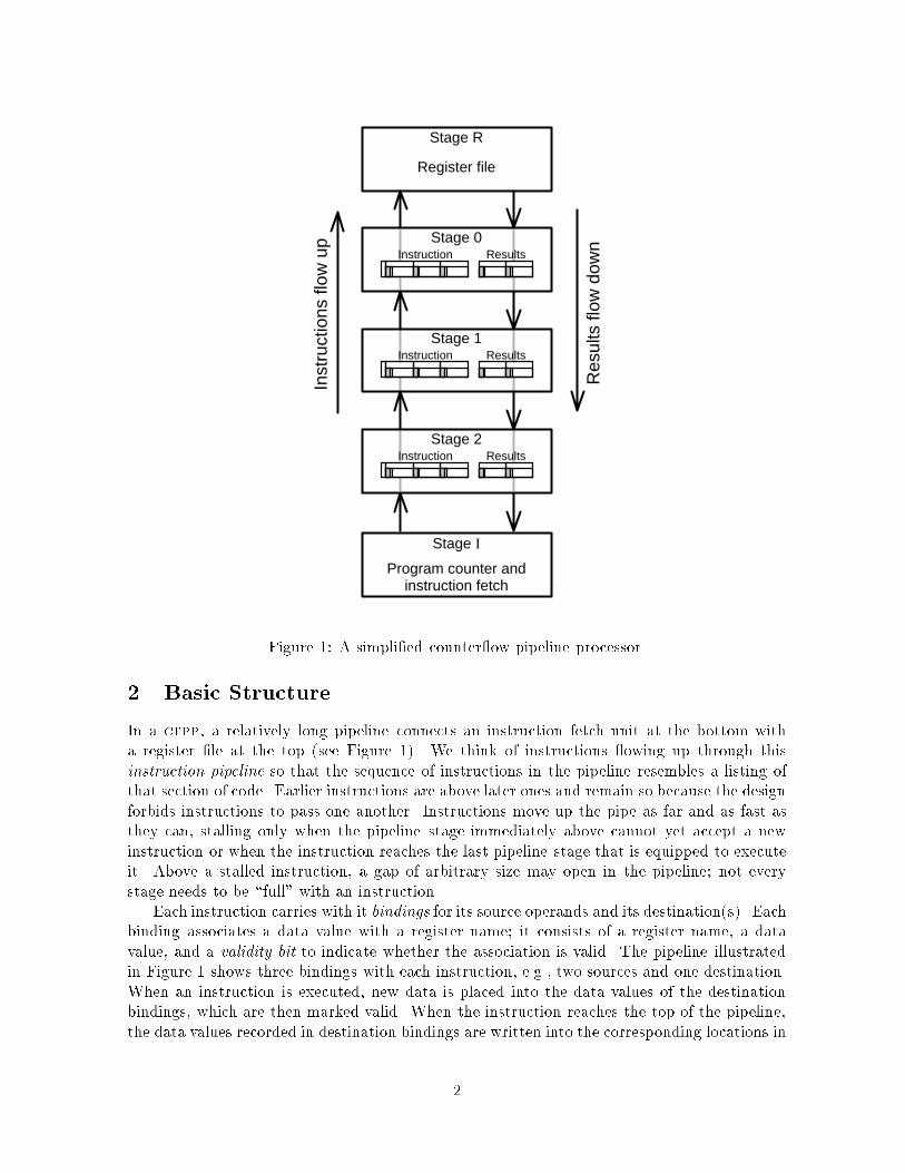
Stage Instruction pipe Result pipe Remarks
R Registers contain: A[14]B[2]C[3]D[21]
0
1
2
I PC = 101 " Fetch, send source names B, C to reg �le
The �rst instruction is fetched and launched into the instruction pipeline with source
and destination bindings that correspond to the register names given in the instruction. All
5
bindings are marked invalid. The instruction that ows up the pipe will also contain the op-
code and possibly other information, such as the program counter. The two source register
names are transmitted to the register �le, so that values can be fetched and inserted into the
results pipeline.
Stage Instruction pipe Result pipe Remarks
R B[2]C[3] # Registers contain: A[14]B[2]C[3]D[21]
0
1
2 A[] := B[] + C[] "
I PC = 102 " Fetch, send source names A, B to reg �le
Stage Instruction pipe Result pipe Remarks
R A[14]B[2] Registers contain: A[14]B[2]C[3]D[21]
0 B[2]C[3] Mustn't swap with instruction below.
1 A[] := B[] + C[] " Mustn't swap with result above.
2 B[] := A[] + B[] "
I PC = 103 Fetch delayed due to cache miss.
Stage Instruction pipe Result pipe Remarks
R A[14]B[2] Registers contain: A[14]B[2]C[3]D[21]
0 A[] := B[2] + C[3] B[2]C[3] # Garner B, C; execute
1 B[] := A[] + B[]
2
I PC = 103 " Fetch, send source name C to reg �le
Stage Instruction pipe Result pipe Remarks
R A[14]B[2] Registers contain: A[14]B[2]C[3]D[21]
0 A[5] := B[2] + C[3] " A[5] Insert result
1 B[] := A[] + B[2] " B[2]C[3] Garner B
2 D[] := C[]� 1 " Literal {1 held in binding value
I PC = 104 Fetch, send source names to reg �le
Stage Instruction pipe Result pipe Remarks
R A[5] := B[2] + C[3] " A[]B[2] Registers contain: A[5]B[2]C[3]D[21]
0 B := A[5] +B[2] " A[5] Garner A, execute
1 D := C[3]� 1 " B[2]C[3] Garner C, execute
2 . . .
I PC = 105 Fetch, send source names to reg �le
In the last snapshot, the binding for A in result stage R has been killed by rule M1. Note
in this example that instructions execute whenever all source operands are available, which is
not necessarily in the order of instruction issue.
6

5 Traps and Conditional Branches
Two of the most troublesome aspects of conventional processor design are handling traps and
conditional branches. The cfpp structure accommodates these cases easily: the basic idea
is that a specially-marked result traveling down the results pipeline invalidates instructions
following a trap or wrongly-predicted branch. If the execution of an instruction causes a
trap, the stage that generates the trap introduces a special trap-result binding into the results
pipeline instead of the normal destination bindings. To invalidate subsequent instructions, we
introduce the following additional pipeline rule that is applied when a result and instruction
meet in a stage:
M3: Kill instruction. If a result binding is either trap-result or wrong-branch-result, mark
the instruction invalid. The instruction may proceed up the pipeline, but it will have no
side e�ects on the results pipeline or the register �le.
When the trap result reaches the bottom of the results pipeline, it is interpreted specially
by the stage responsible for program-counter control (see Figure 3, which shows details of
pipeline stages for instruction fetching): it changes the program counter so as to start fetching
instructions from a suitable trap handler. As these new instructions enter the pipeline, they
will not meet the trap result, and so will remain valid. Note that the trap result may carry
information from the o�ending instruction, such as the program counter or trap condition, to
be used in handling the trap.
Conditional branches are handled in a similar fashion. A conditional-branch instruction,
which cites the condition code register as a source, goes up the instruction pipeline, just like
any other instruction. Meanwhile, the program-counter control makes a branch prediction and
continues to launch instructions into the pipeline from the predicted instruction stream. When
the conditional-branch instruction executes, if it determines that the branch was predicted
incorrectly, it sends down the results pipeline a wrong-branch-result binding, which contains
a value for the correct program counter target of the branch. This special result will kill all
subsequent instructions it meets in the pipeline. When the branch result reaches the program-
counter control stage, the program counter is adjusted to re ect the result of the branch, and
instructions will now be fetched from the proper path.
The activities sketched above for handling conditional branches might usefully be divided
among several stages. The arrangement of Figure 3, for example, splits responsibility for
program-counter control and instruction decoding into separate stages. In this example, the
instruction decoder may be responsible for branch predictions, and may send new program-
counter values to the program-counter stage via the results pipeline.
6 Function Units and Sidings
The cfpp architecture allows di�erent stages to be capable of di�erent kinds of processing.
For example, one stage might execute integer arithmetic instructions, while another does
oating-point. One stage might do adds and another multiplies; if the multiplier is above the
adder in the instruction pipeline, then mul-add sequences used to form inner products will
take advantage of the forwarding o�ered by the results pipe: a multiplication result will be
forwarded quickly to the adder.
Another view of the instruction pipeline is that stages may perform partial execution,
stalling if necessary to be sure that the instruction is su�ciently executed to progress up the
7

Register file
Memory recover
Add recover
Mult recover
Add launch
Mult launch
D cache recover
Memory launch
Decode
I cache recover
I fetch launch
Program counters
I cac
he
Inst
ruct
ions
flow
up
Dat
a ca
che
Res
ults
flow
dow
nA
dder
Dat
a m
emor
y (m
ain)
Mul
tiplie
rS
ourc
e bi
ndin
g na
mes
Figure 3: A counter ow pipeline processor with memory and arithmetic sidings.
pipe. The requirement that an instruction complete execution before being retired into the
register �le is an example of the most stringent of the partial-execution requirements. The
stage or stages that fetch instructions may also be said to accomplish partial execution: they
convert a program counter value into bits that describe an instruction to be executed.
The pipeline may also use auxiliary sidings to execute instructions. A stage in the in-
struction pipeline will launch an operation into a siding, and one or more later stages will
recover results. The sidings themselves are pipelined, so that several operations can be in
progress concurrently. While a siding is performing its job, the instruction that launched the
operation proceeds normally along the instruction pipeline so that it can recover and handle
results in proper sequence with other instructions in the pipe. Note that instructions inval-
8

idated by traps or conditional branches must still recover results from any operations they
have previously launched into sidings, in order to keep the sidings and the instruction pipeline
coordinated.
Figure 3 shows two arithmetic sidings: a multiplier and an adder. When an instruction
calling for an add reaches the stage named add-launch, it stalls if necessary to wait for all
operands to be valid, and then launches the addition into the siding. The instruction proceeds
up the instruction pipeline, and recovers a result from the siding at the stage marked add-
recover, waiting if necessary for the siding operation to �nish. The add-recover stage will put
the result value into its destination binding and launch a result into the results pipeline, just
as if the instruction had been executed using only the resources of the add-recover stage.
Figure 3 also shows a memory siding that has two recovery points. A memory load opera-
tion is launched into the siding at the bottom by providing the address. The memory siding
responds in one of two ways at the �rst recovery point. If the value was present in a cache, it is
delivered at this point and the instruction is fully executed; if not, the memory siding indicates
a miss to the instruction pipeline, and the load instruction advances up the pipeline without
a valid destination binding. At the �nal recovery point, the memory must return a value or
indicate an error, such as a page fault. The objective of this arrangement is to report cached
data values early, so that they may be forwarded quickly down the results pipeline to serve as
operands for instructions that need them. Memory write operations may be launched at the
same point as loads. Processing a write is complicated by the fact that values in memory may
be changed only after traps and conditional branches for all earlier instructions have occurred.
One way to meet this requirement is to require write operations to commit at the last stage
of the instruction pipeline, memory-recover, even though write data might have been supplied
to the siding earlier.
Many siding arrangements are possible; the con�guration shown in Figure 3 shows some
of the possibilities. One drawback of sidings is that they reduce the regularity of the pipeline
design and layout, and may lead to delays or slow paths. On the other hand, since the sidings
are pipelined, high throughput can usually be sustained by su�cient pipelining. The siding
mechanism also suggests a simple way to integrate functionally-specialized coprocessors into a
machine architecture in a way that permits concurrent operation of the processors as well as
perfect synchronization with the instruction stream.
7 Register Files and Register Caches
The architecture permits several separate register �les to co-exist along the pipeline, but any
instruction that may alter the contents of a register in the �le must execute before passing the
corresponding register �le. For example, one might locate separate �xed and oating-point
register �les at di�erent places along the pipe.
A more useful construct is the register cache, which helps reduce the latency entailed in
fetching values from the register �le and passing them down the results pipeline. The register
cache can be located just above the instruction decoder: it enters values into source bindings
for any registers that have valid entries in the cache. Any result binding that passes the cache
may be written into the cache as a valid entry. When an instruction passes the cache, any
values held in the cache that will be overwritten by the instruction must be invalidated in
the cache. Trap results and wrongly predicted branch results need to sweep the cache of any
values computed by instructions subsequent to the trap or branch. Rather than try to identify
these registers exactly, the entire cache can be cleared.
9

The register cache can also reduce the load on the register �le and the results pipeline. To
do so, we let the register cache rather than the instruction decoder send fetch requests to the
register �le. Only if the cache does not contain a needed source operand is a request forwarded
to the register �le. Note that although the path from the instruction decoder or register cache
that transmits requests to the register �le may be physically long, it can be speeded up by
pipelining the communication.
The register �le and register cache both �t into the mold of a standard cfpp stage that
obeys the pipeline rules. The register �le is equivalent to a series of stages that hold recently-
completed instructions; when a binding, injected at the top of the results pipeline to obtain
a source operand, passes the \register-�le instruction" whose destination binding matches the
result binding, the result value is updated (rule M2). Thus, the held instructions behave like
a register �le. Similarly, the register cache is conceptually like a broadening of the results
pipeline to hold a modest number of results at once. The comparison rules dictate how the
cache values �ll in sources (rule M0) and how the cache values are modi�ed (rules M1, M2).
8 Implementations
There are numerous ways to implement cfpp structures. Some of the variations are imme-
diately evident: the number of stages in the pipeline, the choice of functional specialization
of various stages, the choice of sidings and the location of their launch and recovery points,
and so on. This section describes other variations, including the nature of the information
that ows in the instruction and result pipes. Finally, the pipeline can be implemented with
either synchronous or asynchronous circuits; we present a fairly detailed description of an
asynchronous implementation.
The result pipeline carries result bindings. To increase performance, it is desirable to
combine several results together into a �xed-size result packet that ows down the pipeline
as a unit. Figures 1, 2, and Section 4 illustrate result packets containing two bindings. Al-
ternatively, a result packet might contain three bindings, so that all the operands used by a
typical instruction can be carried in a single packet: two full-word operands and a condition
code. The packet structure may make special provision for the condition code binding, whose
value requires only a few bits. Alternatively, one might argue that the instruction and result
pipelines should operate at about the same speed, and therefore a result packet should have
room for all the source and destination bindings for one instruction: perhaps two full-word
operands, a condition-code operand, and a full-word destination. Note that it would not be
necessary to carry a separate condition-code destination binding, because the \source value"
would be overwritten by the \destination value" as the packet passes any instruction that
changes the condition code.
In like fashion, the instruction pipe carries instruction packets. Each instruction carries
its op-code, all source and destination bindings, and perhaps other data such as the value of
the program counter that fetched the instruction. As with the result pipe, it is possible to
place more than one instruction in a single instruction packet; this would be analogous to a
conventional multi-scalar design.
Each stage of the pipeline contains latches for holding an instruction packet and a result
packet. These latches provide the storage that is essential for pipelined processing. Connected
to these latches are circuits to enforce the pipeline rules, including comparators that detect
when instruction and result bindings match (see Figure 2).
10

a b c d
Figure 4: Pipelines operating at maximum throughput have half their latches empty.
8.1 Pipeline Control
The pipeline control we envision for cfpp designs is elastic: new packets can be inserted into
or removed from a stream of packets. Thus, when an instruction executes, it inserts a new
result into the result path. This result could occupy a previously invalid result binding in a
result packet, or it might require inserting a fresh result packet into the result pipe. When
an instruction is killed by a trap or conditional branch, the instruction packet can be deleted
from the instruction pipe unless the instruction must synchronize with a siding. Results that
are killed may be deleted from the results pipe. Note that correctness of the cfpp structure
can be achieved without insertion and deletion. Rather than deleting an instruction or result,
we could simply mark it as invalid and let it propagate through the rest of the pipe without
causing side e�ects. Rather than inserting new result packets, we could send down the result
pipe a continuous supply of result packets that contain empty result binding slots; a result
binding could be inserted in the �rst empty slot to pass after an instruction executes.
A major objective of the cfpp structure is to allow local control of the pipeline: the decision
as to whether a packet may advance to the next stage of the pipeline requires knowing only
the state of the two stages involved in the transfer. There are three conditions that must
be met for advancement: (1) the item must be ready to advance so that, for example, if an
instruction is being executed, the execution must be complete; (2) there must be space in the
next stage; and (3) an instruction and result may not swap, i.e., they may not be exchanged
between adjacent stages. These conditions require only local knowledge.
The need to obtain space in the next stage before advancing has an unexpected conse-
quence: the maximum throughput of a pipeline is achieved when it is half-full. Figure 4a is
a schematic of a uni-directional pipeline with storage latches shown as squares, and combina-
11

E
I R
F
C
arbitrationrequired
arbitrationrequired
AIAR
PI
PR
AR AI
PRPI
Com
p
Figure 5: The state diagram for a single cfpp stage.
tional logic shown as circles. A square representing a latch is darkened if it contains a data
item. The bottom three latches are full and the top latch is empty. Immediately to the right
of the pipeline is a column of squares showing the next state of the pipeline: the top-most
data item has advanced upward. The two remaining columns show subsequent states of the
pipeline. Note that only a single data item moves in each cycle. Figure 4b shows the same
structure with bubbles and data items alternating. This con�guration achieves the maximum
throughput in which each item advances on each cycle, but the pipeline is only half full. To
recover full utilization of the logic, which may be quite extensive if it is performing, for exam-
ple, oating-point arithmetic, two latches can be provided with each stage, as in Figure 4c,
which shows a standard master-slave register for each stage, or as in Figure 4d, which shows
two symmetric latches and a multiplexor to eliminate the need to transfer master to slave.
The highest throughput is achieved when one of the two latches associated with each stage is
full and one is empty. In these con�gurations, each stage is always processing an item through
its logic, and each item can advance.
8.2 Countersynchronized Control
What distinguishes the cfpp from two independent counter owing pipelines is that the two
pipelines interact to enforce matching of instruction and result bindings when they meet, so
that the pipeline rules can be applied. This requirement can be met by inspecting the state
of pairs of adjacent stages and preventing certain items from advancing along their pipes.
Figure 5 shows a state diagram for each pipeline stage that re ects whether an instruction or
result or both are present. The states are named as follows:
E: Empty. Neither instruction nor result is present.
I: Instruction. Only an instruction is present.
12

Com
mun
icat
ion
Pro
cess
Com
munication
Process
Cop
Stage
Stage
PI? Y AR?
AI? X PR?
AI! PR!
PI! AR!
GI GR
Figure 6: The interface between two adjacent stages of an asynchronous implementation of
the cfpp.
R: Result. Only a result is present.
F: Full. Both instruction and result have arrived.
C: Complete. The pipeline rules have been enforced, and both instruction and result are
ready to move on. In practice, this state might be divided further to allow the result to
advance while the instruction is being executed.
The transitions in the state diagram that involve motion of instructions and results are labeled
AI (accept instruction from below), PI (pass instruction upward), AR (accept result from
above), PR (pass result downward). Note that no transitions are allowed in which instructions
and results swap. For example, in state R, either the result may pass down or an instruction
may be accepted from below, but not both.
8.3 Synchronous Implementation
Synchronous implementations of the cfpp are straightforward. Local control is easily achieved
by a combinational function on the state of neighboring stages, each of which uses the represen-
tation of Figure 5. The control can use a �xed policy to decide between passing an instruction
or result packet when either is possible. One sensible policy passes instructions preferentially,
because the ultimate aim of a processor is to shove instructions through the pipe as rapidly
as possible.
13

C
C
C
GI GR
XAI? PR?
PI? Y AR?
R1
G1 G2
R2
D
Arbiter
Cop
Figure 7: The internals of the cop.
A two-speed clocking strategy may be appropriate because many instructions and results
passing through stages will require little or no processing: none if instructions and results are
not both present, and little to enforce the pipeline rules. An instruction may pause longer
in a stage when it is executing. It may be advantageous to use a single very fast clock to
handle the non-execution cases in a single clock cycle, and take more cycles when executing
an instruction.
8.4 Asynchronous Implementation
The cfpp architecture was devised with an asynchronous control structure in mind. Because
the stages are all similar and the interfaces between adjacent stages are identical, we can il-
lustrate the design approach by showing the design of a typical stage and how adjacent stages
communicate. Figure 6 shows the interface between stages, which consists of two communi-
cation processes and a control element named a \cop." Throughout this discussion, we use
transition signaling conventions (also called \two-phase" or \non return to zero") and bundled
data transfer protocols, as illustrated in [10, 9].
Each stage sends signals to the cop indicating what the stage is prepared to do. The
signal AI? indicates willingness to accept an instruction, PI? willingness to pass an instruction
forward, AR? willingness to accept a result, and PR? readiness to pass a result forward.
The cop matches requests to pass with willingness to receive and activates the appropriate
communication process (GI or GR). The communication process, in turn, indicates completion
to the stages it links using the signals PI! and AI! or PR! and AR!. In the event that both
instruction and result communications are possible, the cop chooses one. We selected the name
cop because it controls tra�c between the stages, letting tra�c move only one direction at
a time. After each communication, both participating stages must announce willingness to
participate in the next communication by signaling on the X and Y wires. Only after both
stages have determined that the transfer is complete may the cop allow the next transfer.
14
R1
R2
G1
G2
D
D
D
D
G1G
2R2
R2
R2
R1
R1
R11
0
3
2
5
4
7
6
arbitration required
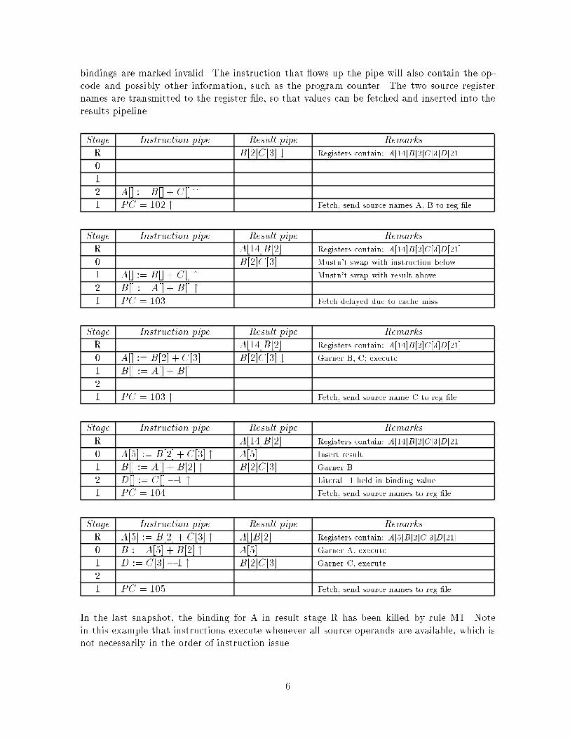
Figure 8: The state diagram of the 5-wire arbiter contained in the cop.
This communication protocol adheres to the �ve-state diagram shown in Figure 5. The
complete process AI?, PI?, GI, AI!, PI!, X, Y corresponds to the act of the lower stage's pass-
ing an instruction to the upper stage. In the 5-state diagram of Figure 5, this transaction is
represented as a single event, called AI by the upper stage and PI by the lower stage. The
interpretation of the event in the state diagram is like that of Communicating Sequential Pro-
cesses (csp) [7] events: it requires agreement and synchronization of the two communicators.
The expansion of this event into the signaling protocol used by the cop requires a delicate
interplay of the state diagrams of adjoining stages and the need for arbitration. It is not the
straightforward two-wire expansion of a csp event [2].
Cop internals. The cop can be implemented with a 5-wire arbiter and C elements as shown
in Figure 7. When both the pass and accept signals for a communication have been presented,
a C element signals a request to the arbiter. When the arbiter produces the corresponding
grant, the communication is enabled, and will eventually occur. Finally, when both stages
indicate they are �nished with the transaction by signaling on X and Y, the arbiter is freed
for the next transaction.
The arbiter exhibits the eight states shown in Figure 8. Only one of these states actually
requires arbitration; it is indicated in the �gure. Notice that R1 and G1 alternate, as do R2
and G2, while either of the grants alternate with D.
Communication processes. Instructions and results ow from stage to stage in a form of
micropipeline as shown in Figures 6 and 9a. The instruction transfer process, shown in the
�gure as an oval, is told by the cop to act (GI). It moves an instruction from one stage to the
next, latches it, and informs both stages that the transfer is complete (AI! and PI!). There is a
clear correspondence between the cfpp structure (Figure 9a) and that of a micropipeline [10]
15

AI!
PI!
GIC
AI?
PI?
1/2 Arbiter
Cop
Stage
Stage
C
AI! AI?
PI?PI!
ba
Latch
Figure 9: The stage-to-stage communications of the cfpp (a) compared to those of a mi-
cropipeline (b).
(Figure 9b). The only signi�cant di�erence is the arbitration required to enable a transfer.
The communication process represented by the oval can be implemented in a variety of
ways, such as serial communication, purely self-timed data, etc. The wiring shown in the
illustration is chosen to match most closely the micropipeline form. The latch is initially
transparent, so that input data ows to its outputs (data paths are not shown in the illustra-
tion). The GI signal will cause the latch to become opaque, so as to hold its output values,
and then generate the AI!/PI! output. Finally, a transition on the signal that enters the latch
diagonally returns it to a transparent state. Note that the pipeline latches could be physically
associated with either of the two stages or with the cop.
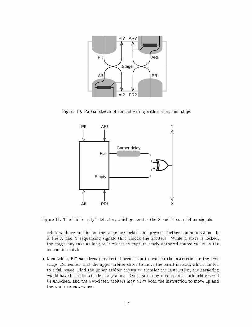
Stage internals. Figure 10 shows an over-simpli�ed view of connections within a pipeline
stage that implement the instruction and result pipelines. Control wiring connects the commu-
nication processes so that when a new instruction is received (AI!), the stage asks immediately
to pass it onward (PI?), and when it has been passed (PI!), the stage immediately requests
another (AI?). Similar wiring handles results.
The remaining component of each stage is a \full-empty detector" shown in Figure 11. It
takes as input the four communication completion signals and announces when a stage has
become full or empty. A full signal starts the garnering process. This process leads to two
subtle behaviors:
� Until the garnering process is �nished and the X and Y signals have reached the adjacent
cops, the instruction and result are locked in the stage. The lock occurs because the
16
Stage
AI!
AI? PR?
PI? AR?
PI!
PR!
AR!
Figure 10: Partial sketch of control wiring within a pipeline stage.
PI! AR!
AI! PR!
Garner delayFull
Empty
Y
X
Figure 11: The \full-empty" detector, which generates the X and Y completion signals.
arbiters above and below the stage are locked and prevent further communication. It
is the X and Y sequencing signals that unlock the arbiters. While a stage is locked,
the stage may take as long as it wishes to capture newly garnered source values in the
instruction latch.
� Meanwhile, PI? has already requested permission to transfer the instruction to the next
stage. Remember that the upper arbiter chose to move the result instead, which has led
to a full stage. Had the upper arbiter chosen to transfer the instruction, the garnering
would have been done in the stage above. Once garnering is complete, both arbiters will
be unlocked, and the associated arbiters may allow both the instruction to move up and
the result to move down.
17

This design places all the required arbitration in the cops, and allows processing within each
stage to assume that a new result or instruction may arrive during the processing, but that
neither instruction nor result may leave the stage until the processing is complete and the X
and Y signals unlock the cops.
Instruction execution can take two forms. First, an instruction that has garnered all its
operands might be executed as it passes through a stage. The data path from instruction
latch to instruction output implied by Figure 10 will contain suitable combinational logic for
execution. The control path in the �gure linking AI! and PI? may need a delay that corresponds
to the logic delay. Second, some instructions may need to await additional operands. In
this case, suitable control circuitry must inhibit producing a PI? event. The instruction will
garner sources from passing results, and will be executed during the �nal garnering process,
which must then generate PI?. We have found it challenging to design simple, fast, correct
implementations of the complete control circuitry.
9 Discussion
The sketches of the cfpp architecture and its implementation presented in this paper are
merely beginnings. The structure admits a great many variations, and raises a number of
questions, such as:
� What is a suitable organization of stages and their capabilities for e�cient processing
of instruction streams of the sort that conventional risc processors accept? Does the
forwarding mechanism o�ered by the results pipeline allow greater concurrency than
conventional risc pipeline designs?
� What sorts of instruction-ordering and other compile-time measures can be taken to
improve the performance of a cfpp pipeline?
� How can the asynchronous implementation be improved? Are there stage-to-stage sig-
naling protocols that would allow higher instruction throughput? Is it wise to reduce
the use of arbitration, or is arbitration su�ciently fast in the normal case that it can be
used more freely?
� Is the latency of operand delivery via the results pipeline too great to be practical? One
view is that the critical delay in a processor extends from the moment a value is computed
until the next instruction that depends on that value is identi�ed and both instruction
and value are delivered to a computational unit that can execute the instruction. Is the
counter ow pipeline a practical mechanism to achieve this control and communication?
� What is the best performance that can be expected from a cfpp design, and can the
structure compete with alternative processor architectures?
The last question is, of course, critical. The cfpp design calls for more circuitry than a
conventional design, e.g., in the comparators required to implement the pipeline rules. Does
the performance of the cfpp justify this cost alone? Or is the cfpp su�ciently easier to design
than a conventional processor that the reduced design time is attractive?
The cfpp design is an extreme attempt to replace physically long communication paths
on a chip with pipelined transport of data and instructions. As chip densities and transistor
performance increase, the relative delay of long wires increases. Our hope is that a small
18

number of very fast local pipeline transfers can replace a single, longer delay required to send
bits an equivalent distance. Whether this aim can be achieved awaits further simulation and
implementation studies.
At the opposite extreme from the cfpp is a data ow architecture, in which a new result is
broadcast to an associative memory that holds instructions waiting to be executed [8]. The new
result may complete the source values required to execute one or more of these instructions;
they are identi�ed, read out of the associative memory, and routed to a suitable functional unit.
The comparators in the associative memory perform the same function as the comparators
that enforce the pipeline rules in the cfpp. However, the data ow mechanism depends on
broadcasting data to an associative memory that presents a large load and long pathways to
the broadcast wires, and that slows the operation.
Ideally, we would like to compare the performance of these two extreme designs in a
closed form, such as provided by logical e�ort [11]. Perhaps the best design is a compromise
between entirely data ow and entirely pipelined extremes. For example, one could imagine
treating small blocks of instructions in a data ow fashion, but pipelining the blocks through the
processor: results would be presented in one cycle to a few immediately following instructions,
and then later to subsequent blocks.
The simple, regular structure of the cfpp design leads to bene�ts such as modularity, ease
of layout, and simple correctness arguments. Whether these bene�ts outweigh some of the
apparent disadvantages of the structure is a question left to further work.
10 Acknowledgements
The cfpp is known colloquially as the \Sproull pipeline processor" because the basic idea was
devised by Sproull, perhaps because Sutherland was about to arrive in Boston for a summer's
work, and self-defense required that some attractive \idea concentrator" be available for focus.
To Sproull, the counter ow pipeline was inspired by Sutherland's playing with the idea of two
asynchronous fifos running in opposite directions, itself an outgrowth of the observation that
data can ow backward in the fast fifo described in [10], although the control circuitry for
the fifo seems to preclude exploiting this feature.
The asynchronous implementation proved to be quite di�cult, not merely a simple compo-
sition of asynchronous modules that we had studied earlier [1, 3, 4]. Molnar, whom we enlisted
to help with our design, proposed the 5-state diagram and the 5-wire signaling protocol to im-
plement it. We have since attempted a wide variety of implementation alternatives. We have
made constant use of software based on Dill's veri�er [5]; it has detected many protocol errors
and inconsistencies. We have found the asynchronous design task very hard, perhaps because
we are striving for performance as well as modularity.
The project would not have been possible without the energy, inspiration, and contributions
of Ian Jones, Chris Kappler, Mike Wessler, and Robert Yung. The authors are extremely
grateful to Wes Clark, who gave this paper a meticulous critique.
19

Appendix: Correctness arguments
The simplicity of the cfpp should facilitate a proof of its correctness. We address two correct-
ness concerns: safety|that the structure makes only correct state transitions in the machine
state, and liveness|that all instructions eventually execute. For example, we must demon-
strate that deadlock cannot occur, e.g., if an instruction stalls waiting for a source operand
that is never transmitted down the results pipeline.
We present here an outline of a proof, assuming a simple cfpp without memory, sidings,
traps, conditional branches, or a register cache. As a \gold standard" for comparison, consider
a simple sequential implementation and a numbering that indexes instructions executed, in
order of execution: I [0]; I [1]; I [2]; etc. This same numbering identi�es successive states of the
entire register �le: the age of the register �le is j when it re ects execution of all instructions
with index less than j. Each value stored in the register �le has a lifetime that is the range of
register ages in which the value is valid. We use the notation R[b : d] to indicate a value stored
in register R with a lifetime b : d. This value is a valid source for any instruction with index
j such that b � j � d: we say that the lifetime includes j. The simple sequential machine can
be characterized as follows. Instruction I [j] computes a destination value D[j + 1 : d] such
that:
� D[j + 1 : d] = f(S1[b1 : d1]; S2[b2 : d2]; :::), where f is the computation called for by
instruction I [j] and each of the sources has a lifetime that includes j, i.e., bi � j � di.
Note that because lifetimes partition the execution sequence, the requirement that the
source lifetime include j uniquely identi�es each source.
� d = min i such that i > j and I [i] also has destination register D.
Our objective is to demonstrate that the results computed by the cfpp are the same
as those computed by the simple machine. We devise a succession of invariants that are
consequences of the pipeline organization and pipeline rules and of other invariants:
I1 The age of the register �le increases monotonically, without gaps. In other words, when
the register �le has age j, the next instruction to be retired is I [j], after which the register
�le will have age j+1. This property is true because every instruction is launched into the
instruction pipeline and P0 requires that instructions stay in order within the pipeline.
Recall that we are not dealing here with traps or branches that might kill instructions.
I2 If pipe stage p holds a valid result R, the lifetime of the result is the same as that
of a destination of the closest instruction at or above p in the instruction pipe whose
destination name matches the result name. If there is no such instruction in the pipe,
the lifetime of R is the same as that of the value of R in the register �le. This invariant
follows from the way results are fetched from the register �le and modi�ed by rule M2 or
injected by rule P2. A result killed according to rule M1 is not a valid result; hence the
antecedent of this invariant is not true.
I3 The lifetime of any valid result R in the pipe is equal to that of the destination value of the
closest preceding instruction in the instruction sequence that has the same destination
register name. To be more precise, if pipe stage p holds R, let j be the index of the
instruction in p, or if p is empty, the nearest instruction above p, or if there are no
instructions above p, the age of the register �le. Then the lifetime of R is that of the
20

destination value of the instruction k where k is the least value � j such that a destination
register name of I [k] matches R. This invariant follows from I2 and the way instructions
are retired into the register �le.
I4 For any valid result R in the same pipe stage as an instruction I [j], R's lifetime includes
j. Follows from I3 and the de�nition of lifetime.
I5 Any valid source that is carried along with I [j] has a lifetime that includes j. Conclude
from I4 and M0. This invariant shows that garnering always �nds the proper source
value.
I6 When instruction I [j] executes, the lifetime of each of its source values includes j. Con-
clude from I5, P1, and P3.
I7 For any instruction I [j] in the pipe, for every invalid source in that instruction, either
there is a valid result whose name matches that of the source higher up in the result
pipe, not including the register �le or such a result will be inserted by the execution of
an instruction I [k], k < j. When an instruction is launched into the pipe, the instruction
decoder tells the register �le to fetch a value for each source and send it down the results
pipe. Rule M1 can invalidate a result, but the same instruction that invoked M1 must
execute before leaving the pipeline; when it does, P2 requires that it insert a valid new
result binding with the same name as that of the result that it deleted.
I8 Results are able to move down the result pipeline to meet any instruction that needs
them. The result in the bottom stage can leave freely, thus creating a bubble into which the
next result can move, and so on. A result immediately above a bubble eventually moves
down, even if the stage-to-stage communication protocol favors instruction movement.
The reason is that if results do not move, then some instruction will stall waiting for its
source values, and eventually the instruction pipeline will plug up, allowing no further
movement. At this point, results will move down the result pipe.
I9 Every instruction launched is eventually executed. This follows almost directly from I7
and I8, which say that all sources are eventually �lled in, and P1 and P3. To be precise,
we need to argue by induction on the index of completed instructions to be sure that the
instruction I [j] mentioned in I7 is executed.
This chain of reasoning establishes that the basic cfpp computes the correct result (I6) and
makes progress (I9). This proof sketch suggests a framework for a complete proof involving
more complex pipelines, including register caches, trap handling, and conditional branching.
21

References
[1] Brunvand, E. L. \Parts-r-Us: A Chip Aparts." Technical Report CMU-CS-87-119, Com-
puter Science Dept., Carnegie Mellon University, 1987.
[2] Brunvand, E. L., and R. F. Sproull. \Translating concurrent communicating programs
into delay-insensitive circuits." ICCAD, 1989.
[3] Clark, W. A. \Macromodular computer systems." In Proc. Spring Joint Computer Conf.,
AFIPS, April 1967.
[4] Clark, W. A., and C. E. Molnar. \Macromodular computer systems." In Computers in
Biomedical Research, Vol. 4, R. Stacy and B. Waxman, eds., Academic Press, New York,
1974, 45{85.
[5] Dill, D. L. Trace theory for automatic hierarchical veri�cation of speed-independent cir-
cuits. MIT Press, Cambridge, MA, 1989.
[6] Hennessy, J. L., and D. A. Patterson. Computer Architecture: A Quantitative Approach.
Morgan Kaufman, San Mateo, CA, 1990.
[7] Hoare, C. A. R. Communicating Sequential Processes. Prentice-Hall, 1985.
[8] Popescu, V., M. Schultz, J. Spracklen, G. Gibson, B. Lightner, and D. Isaman. The
Meta ow Architecture. IEEE Micro (June 1991): 10{72.
[9] Seitz, C. L. \System Timing." In C. A. Mead and L. Conway, Introduction to VLSI
Systems. Addison-Wesley, 1980.
[10] Sutherland, I. E. \Micropipelines." Comm. ACM 32, 6 (1989): 720{738.
[11] Sutherland, I. E., and R. F. Sproull. \Logical E�ort: Designing for Speed on the Back
on an Envelope." In Advanced Research in VLSI, Carlo H. S�equin, ed., MIT Press,
Cambridge, MA, 1991.
22
About the authors
Robert F. Sproull is presently Vice President and Fellow at Sun Microsystems Laboratories.
He leads a section of the laboratory in Chelmsford, Mass. that focuses on improving users'
coupling to computers and information. Since undergraduate days, he has been building hard-
ware and software for computer graphics: early clipping hardware, an early device-independent
graphics package, page description languages, laser printing software, and window systems. He
has also been involved in VLSI design, especially of asynchronous circuits and systems. Prior
to joining Sun, he was a principal with Sutherland, Sproull and Associates, an associate pro-
fessor at Carnegie Mellon University and a member of the Xerox Palo Alto Research Center.
He is a coauthor with William Newman of the early text, Principles of Interactive Computer
Graphics.
Ivan E. Sutherland is widely known for his pioneering contributions. His 1963 MIT PhD thesis,
Sketchpad, opened the �eld of computer graphics. His 1966 work, with Sproull, on a head-
mounted display anticipated today's virtual reality by 25 years. He is co-founder of Evans and
Sutherland, which manufactures the most advanced computer image generators now in use.
As head of the Computer Science Department at Caltech he helped make integrated circuit
design an acceptable �eld of academic study. Dr. Sutherland is on the boards of several
small companies and is a member of the National Academy of Engineering and the National
Academy of Sciences, the ACM and IEEE. He received the ACM's Turing Award in 1988.
Charles E. Molnar is Professor in the Institute for Biomedical Computing of Washington
University and a consultant to Sun Microsystems Laboratories. He received B.S. and M.S.
degrees from Rutgers University and an Sc. D. from The Massachusetts Institute of Technology,
all in Electrical Engineering. He has studied asynchronous systems since his involvement in
the Washington University Macromodule Project in 1965{75, and has had special interests in
computer systems for biomedical research applications and in the relationship of models for
computation to mechanisms that compute.
23


