Counterweight Rope Replacement on the Murray Morgan Bridge HEAVY MOVABLE STRUCTURES, INC. 13 th Biennial Movable Bridge Symposium Counterweight Rope Replacement On The Murray Morgan Lift Bridge By: Frank Marzella, PE Hardesty & Hanover, LLP
Transcript
Counterweight Rope Replacement on the Murray Morgan Bridge
HEAVY MOVABLE STRUCTURES, INC. 13th Biennial Movable Bridge Symposium
Counterweight Rope Replacement On The Murray Morgan Lift Bridge
By: Frank Marzella, PE
Hardesty & Hanover, LLP
Counterweight Rope Replacement on the Murray Morgan Bridge
HEAVY MOVABLE STRUCTURES, INC. 13th Biennial Movable Bridge Symposium
Project Background In 2010, the Murray Morgan Lift Bridge at the age of 98, 56 of the original 64 counterweight ropes were still in service. The remaining eight ropes were removed and replaced at various times from 1974 through 2007 for strength testing and inspection. Since the early 1990’s, the Washington State Department of Transportation has been performing detailed wire rope inspections on the counterweight ropes due to escalating concerns over their age and remaining useful life. Through the years strength tests had been performed on various test ropes. The results of these tests indicated that the ultimate strength of the test specimens was satisfactory. However, determining exactly when vertical lift bridge counterweight ropes have exceeded their useful life is quite complicated. Numerous other factors including wear, wire breaks, wire fatigue, external and internal corrosion, internal nicking, fiber core breakdown and socket corrosion/wear all need to be considered. In the fall of 2007, during the aftermath of the collapse of the I-35W Bridge in Minnesota, concerns regarding the overall structural condition of the Murray Morgan Bridge mounted. Paul Hammond (Secretary of Transportation – Washington State DOT) made the unpopular decision to close the Murray Morgan Bridge to vehicular traffic. With the closing of the bridge, Fire, Police, Emergency Services and the general public were now required to detour around this vital link between Downtown Tacoma and the industrial Tide Flats. Ongoing negotiations between the bridge owner (Washington State DOT) and the City of Tacoma continued on rehabilitation options for the aging lift bridge and its approaches. A phased approach to completely rehabilitate the bridge was developed. The first phase would include replacement of the 64 counterweight ropes and the counterweight side equalizer assemblies, as the counterweight ropes were condemned near the end of 2008. Replacement of these counterweight ropes and equalizers would prove to be a daunting challenge on this nearly 100 year old lift bridge. The design engineering and construction methods used to replace the counterweight ropes and equalizers are the main subjects of this paper. Bridge General Description The Murray Morgan Bridge crosses the Thea Foss Waterway in Tacoma, Washington. The bridge has a total length of approximately 1760 feet, and is comprised of three distinct sections – the south approach, a multi-span steel girder structure, erected in 1913; the north approach, a multi-span prestressed concrete girder structure built in 1954 to replace the original approach structure; and a three span steel through truss (approximately 600 feet long) main water crossing with a 221 foot long Pratt through truss vertical lift span built in 1913. The Murray Morgan Bridge is one of the last remaining examples of the Waddell and Harrington’s (predecessors of Hardesty & Hanover, LLP) original span drive type vertical lift bridge designs. It was placed on the National Register of Historic Places on July 16, 1982.
Counterweight Rope Replacement on the Murray Morgan Bridge
HEAVY MOVABLE STRUCTURES, INC. 13th Biennial Movable Bridge Symposium
Murray Morgan Bridge – May 2010 Temporary Lift Span & Counterweight Supports and Structural Strengthening Vertical lift bridges of this vintage were not designed with long term maintenance and component replacement in mind. There were no existing counterweight hangars built into the original lift towers. The counterweight ropes were directly pinned to the lift span and to the equalizer plates on the counterweight side. No means of tensioning or de-tensioning the counterweight ropes was part of the original construction. Since the equalizer assemblies were badly corroded and non-functional, they were to be replaced as well. Previous counterweight tension measurements indicated that equalization of load between the counterweight ropes was very poor. These conditions dictated that both the lift span proper and the two counterweights would need to be temporarily supported in order to replace all the counterweight ropes and equalizers simultaneously.
Counterweight Rope Replacement on the Murray Morgan Bridge
HEAVY MOVABLE STRUCTURES, INC. 13th Biennial Movable Bridge Symposium
Preliminary analysis indicated the following:
• Supporting the counterweights in their raised positions within the lift towers was not feasible because the tower legs lacked sufficient strength to support them.
• Counterweights would have to be supported from the deteriorated roadway deck and floor system below. This would require structural strengthening and shoring for transfer of the counterweight loads to their respective pier foundations.
• The lift span would have to be supported in the raised position with temporary columns under the four live load shoe assemblies. This would allow the navigation channel to remain open during the construction period.
• While the lift piers were originally designed to support the full weight of the lift span, the questionable condition of the lift pier concrete required bolstering to safeguard against concrete blowout.
The general arrangement of the temporary lift span and counterweight supports is shown in Figures 1. Four steel W14 x 120 columns were placed under each live load shoe of the lift span. Each column was anchored longitudinally to the front lift tower leg structural steel and the column bases were anchored to the pier cap concrete.
Counterweight Rope Replacement on the Murray Morgan Bridge
HEAVY MOVABLE STRUCTURES, INC. 13th Biennial Movable Bridge Symposium
Figure 1: Lift Span and Counterweight Support Concept
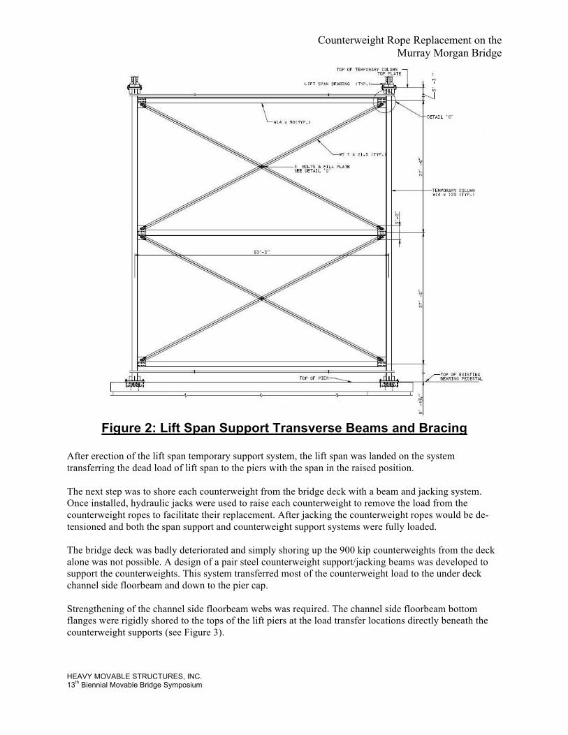
A braced frame was created using W14 x 90 sections for the beams and WT 7 x 21.5 sections for the X bracing (see Figure 2).
Counterweight Rope Replacement on the Murray Morgan Bridge
HEAVY MOVABLE STRUCTURES, INC. 13th Biennial Movable Bridge Symposium
Figure 2: Lift Span Support Transverse Beams and Bracing
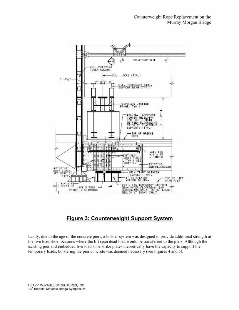
After erection of the lift span temporary support system, the lift span was landed on the system transferring the dead load of lift span to the piers with the span in the raised position. The next step was to shore each counterweight from the bridge deck with a beam and jacking system. Once installed, hydraulic jacks were used to raise each counterweight to remove the load from the counterweight ropes to facilitate their replacement. After jacking the counterweight ropes would be de-tensioned and both the span support and counterweight support systems were fully loaded. The bridge deck was badly deteriorated and simply shoring up the 900 kip counterweights from the deck alone was not possible. A design of a pair steel counterweight support/jacking beams was developed to support the counterweights. This system transferred most of the counterweight load to the under deck channel side floorbeam and down to the pier cap. Strengthening of the channel side floorbeam webs was required. The channel side floorbeam bottom flanges were rigidly shored to the tops of the lift piers at the load transfer locations directly beneath the counterweight supports (see Figure 3).
Counterweight Rope Replacement on the Murray Morgan Bridge
HEAVY MOVABLE STRUCTURES, INC. 13th Biennial Movable Bridge Symposium
Figure 3: Counterweight Support System
Lastly, due to the age of the concrete piers, a bolster system was designed to provide additional strength at the live load shoe locations where the lift span dead load would be transferred to the piers. Although the existing pier and embedded live load shoe strike plates theoretically have the capacity to support the temporary loads, bolstering the pier concrete was deemed necessary (see Figures 4 and 5).
Counterweight Rope Replacement on the Murray Morgan Bridge
HEAVY MOVABLE STRUCTURES, INC. 13th Biennial Movable Bridge Symposium
Figure 4: Elevation View of Pier Concrete Bolster
Figure 5: Plan View of Pier Concrete Bolster
Counterweight Rope Replacement on the Murray Morgan Bridge
HEAVY MOVABLE STRUCTURES, INC. 13th Biennial Movable Bridge Symposium
Counterweight Rope Selection The original 64 counterweight ropes on the Murray Morgan Bridge (installed circa 1912) had the following characteristics: Diameter: 1-1/2 inch Diameter Construction: 6 x 19 Warrington, Right Regular Lay Core: Hemp Fiber Core Material: Plow Steel Min. Ultimate Strength: 175,000 pounds Safety Factor: 6 to 1 (equal tension assumed) Numerous aspects of the counterweight ropes on the Murray Morgan Bridge did not meet modern day American Association of State Highway and Transportation Officials (AASHTO) code requirements. This is not surprising for a nearly 100 year old vertical lift bridge. Replacement rope selection was based on making as many improvements as possible without making costly changes to the rope size or attachment systems. The 2008 AASHTO LRFD Movable Highway Bridge Design Specification contains significant changes to wire rope design used on movable bridges. First, the use of Independent Wire Rope Cores (IWRC) is now allowed in lieu of fiber cores. This is a timely change as domestic wire rope suppliers are reluctant to produce fiber core wire ropes in relatively small quantities. IWRC ropes offer significant improvement in strength over a fiber core rope of the same size and construction. Secondly, AASHTO also now allows the use of Extra Improved Plow Steel (EIPS) for movable bridge wire rope. Using EIPS rope for the counterweight ropes on Murray Morgan would also improve the strength and service factor. The replacement counterweight ropes for the Murray Morgan Bridge were therefore specified as follows: Diameter: 1-1/2 inch Diameter Construction: 6 x 19 Warrington, Right Regular Lay Core: Independent Wire Rope Core Material: Extra Improved Plow Steel Min. Ultimate Strength: 228,000 pounds Safety Factor: 8 to 1 (equal tension assumed) Length Tolerance: +/- .125 inches Two test specimens produced from the supplied rope material were pulled to destruction and had ultimate strengths of 233,700 lbs and 247,600 lbs, providing even greater than expected strength.
Counterweight Rope Replacement on the Murray Morgan Bridge
HEAVY MOVABLE STRUCTURES, INC. 13th Biennial Movable Bridge Symposium
Equalizer Assembly The pinned equalizer assemblies were frozen and heavily deteriorated. Since there was no freedom of movement, rope tension equalization was very poor with some counterweight ropes varying by as much as 38% from the average tension value.
Photo 1: Original Equalizer Assembly
Photo 2: Frozen Equalizer Assembly Removed By Flame Cutting
Counterweight Rope Replacement on the Murray Morgan Bridge
HEAVY MOVABLE STRUCTURES, INC. 13th Biennial Movable Bridge Symposium
Details were developed for replacement of the equalizer assemblies utilizing high strength steel plate and forged steel pins. Rope orientation and layout diagrams were also developed and shown in the plan set (see Figure 6).
Figure 6: New Equalizer Assembly Detail
Counterweight Rope Replacement on the Murray Morgan Bridge
HEAVY MOVABLE STRUCTURES, INC. 13th Biennial Movable Bridge Symposium
Construction Phase In 2009, a construction contract was awarded to Rognlins Inc. of Aberdeen Washington to replace the counterweight ropes and equalizer assemblies on the Murray Morgan Bridge. In order to avoid the high costs of utilizing a barge crane, Rognlins modified the temporary lift span support columns to include a spliced connection. This made it possible to stick build the lift span supports without heavy equipment and without working from the channel (see Photo 3).
Photo 3: Erection of Lift Span Temporary Support Column
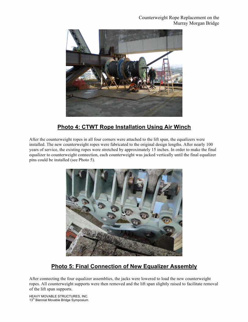
Another cost savings method utilized by Rognlins was to remove the old counterweight ropes and raise the new ones using air operated winches. Again this eliminated the need for expensive heavy equipment. One by one, an old counterweight rope was lowered to the ground and its replacement rope was then raised and laid into its place on the counterweight sheaves (see Photo 4).
Counterweight Rope Replacement on the Murray Morgan Bridge
HEAVY MOVABLE STRUCTURES, INC. 13th Biennial Movable Bridge Symposium
Photo 4: CTWT Rope Installation Using Air Winch
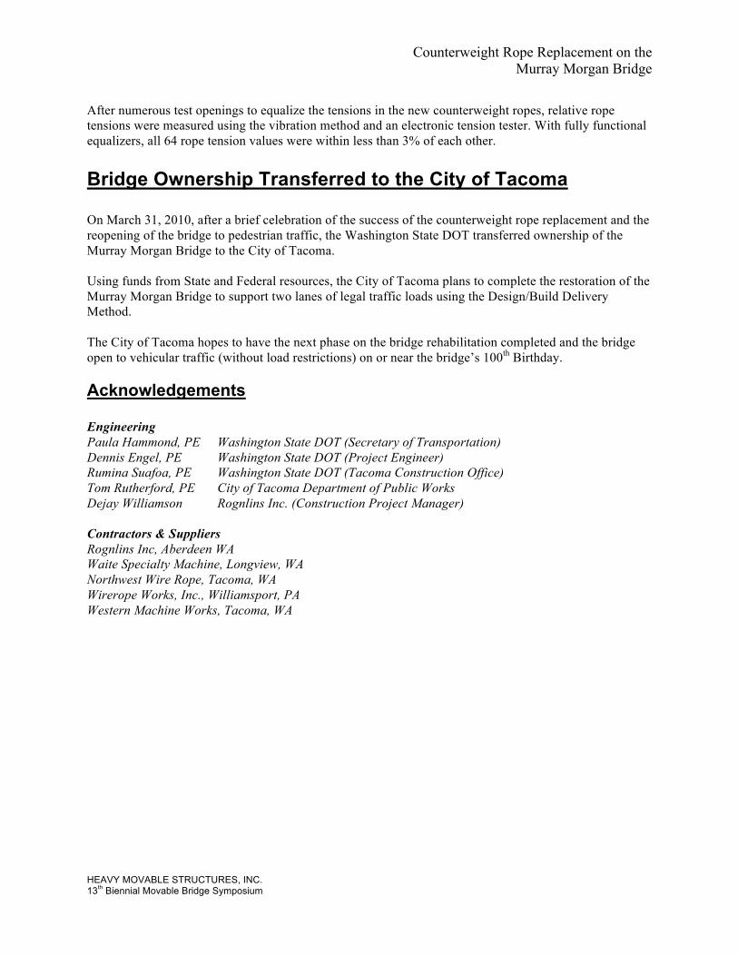
After the counterweight ropes in all four corners were attached to the lift span, the equalizers were installed. The new counterweight ropes were fabricated to the original design lengths. After nearly 100 years of service, the existing ropes were stretched by approximately 15 inches. In order to make the final equalizer to counterweight connection, each counterweight was jacked vertically until the final equalizer pins could be installed (see Photo 5).
Photo 5: Final Connection of New Equalizer Assembly
After connecting the four equalizer assemblies, the jacks were lowered to load the new counterweight ropes. All counterweight supports were then removed and the lift span slightly raised to facilitate removal of the lift span supports.
Counterweight Rope Replacement on the Murray Morgan Bridge
HEAVY MOVABLE STRUCTURES, INC. 13th Biennial Movable Bridge Symposium
After numerous test openings to equalize the tensions in the new counterweight ropes, relative rope tensions were measured using the vibration method and an electronic tension tester. With fully functional equalizers, all 64 rope tension values were within less than 3% of each other. Bridge Ownership Transferred to the City of Tacoma On March 31, 2010, after a brief celebration of the success of the counterweight rope replacement and the reopening of the bridge to pedestrian traffic, the Washington State DOT transferred ownership of the Murray Morgan Bridge to the City of Tacoma. Using funds from State and Federal resources, the City of Tacoma plans to complete the restoration of the Murray Morgan Bridge to support two lanes of legal traffic loads using the Design/Build Delivery Method. The City of Tacoma hopes to have the next phase on the bridge rehabilitation completed and the bridge open to vehicular traffic (without load restrictions) on or near the bridge’s 100th Birthday. Acknowledgements Engineering Paula Hammond, PE Washington State DOT (Secretary of Transportation) Dennis Engel, PE Washington State DOT (Project Engineer) Rumina Suafoa, PE Washington State DOT (Tacoma Construction Office) Tom Rutherford, PE City of Tacoma Department of Public Works Dejay Williamson Rognlins Inc. (Construction Project Manager) Contractors & Suppliers Rognlins Inc, Aberdeen WA Waite Specialty Machine, Longview, WA Northwest Wire Rope, Tacoma, WA Wirerope Works, Inc., Williamsport, PA Western Machine Works, Tacoma, WA