Computer Applications in Electrical Engineering Vol. 14 2016 DOI 10.21008/j.1508-4248.2016.0023 256 Coupled static and dynamic FE analyses of a nonlinear electromechanical vibration energy harvester Marcin Kulik, Mariusz Jagieła Opole University of Technology 45–758 Opole, ul. Prószkowska 76, e–mail: [email protected]The paper presents the coupled static and dynamic mechanical–electromagnetic finite element analyses of an electromechanical vibration energy harvesting converter with permanent–magnet excitation. The system consists of a small, milliwatt power range, linear–motion generator connected to a cantilever–beam spring element. The finite element equations derived for the mechanical part of the system according to the 1–D Timoshenko beam theory are coupled strongly with those describing the 2–D distribution of magnetic field in the generator and those associated with the electric circuit. The considered electromechanical coupling allows for prediction of static and dynamic response of the system subjected to action of externally applied force. The static displacement of the moving element is computed via solution of the nonlinear system of equations and is used as an initial solution in dynamic analysis. For computation of the dynamic response of the system the time–stepping procedure based on the Crank–Nicolson discretisation schema is applied. The models are positively validated against the measurements carried out on the laboratory test–stand. KEYWORDS: energy harvesting, coupled structural–electromagnetic analysis, finite element analysis 1. Introduction An interest in energy harvesting systems is related with growing amount of autonomous and wireless systems, like those used in condition monitoring of industrial machinery. One group of these converters are the harvesters of mechanical vibrations’ dissipation energy [1–13]. The general operation principle of these converters relies upon matching the frequency of internal resonance of the converter with that of the dissipative system. This works analyses the electromechanical energy harvester comprising of a cantilever beam spring element driving a linear–motion permanent–magnet generator with a single–phase cored armature winding [2, 3]. The generator produces alternating voltage with the magnitude that within certain range of the operation bandwidth is proportional to the magnitude and frequency of the externally applied excitation force. The process of energy harvesting by the considered system is much more complex than that by those with coreless generators, as the system kinematics is nonlinear due to the electromagnetic
Transcript
Computer Applications in Electrical Engineering Vol. 14 2016
DOI 10.21008/j.1508-4248.2016.0023
256
Coupled static and dynamic FE analyses of a nonlinear
electromechanical vibration energy harvester
Marcin Kulik, Mariusz Jagieła Opole University of Technology
The paper presents the coupled static and dynamic mechanical–electromagnetic finite element analyses of an electromechanical vibration energy harvesting converter with permanent–magnet excitation. The system consists of a small, milliwatt power range, linear–motion generator connected to a cantilever–beam spring element. The finite element equations derived for the mechanical part of the system according to the 1–D Timoshenko beam theory are coupled strongly with those describing the 2–D distribution of magnetic field in the generator and those associated with the electric circuit. The considered electromechanical coupling allows for prediction of static and dynamic response of the system subjected to action of externally applied force. The static displacement of the moving element is computed via solution of the nonlinear system of equations and is used as an initial solution in dynamic analysis. For computation of the dynamic response of the system the time–stepping procedure based on the Crank–Nicolson discretisation schema is applied. The models are positively validated against the measurements carried out on the laboratory test–stand. KEYWORDS: energy harvesting, coupled structural–electromagnetic analysis, finite element analysis
1. Introduction
An interest in energy harvesting systems is related with growing amount of autonomous and wireless systems, like those used in condition monitoring of industrial machinery. One group of these converters are the harvesters of mechanical vibrations’ dissipation energy [1–13]. The general operation principle of these converters relies upon matching the frequency of internal resonance of the converter with that of the dissipative system.
This works analyses the electromechanical energy harvester comprising of a cantilever beam spring element driving a linear–motion permanent–magnet generator with a single–phase cored armature winding [2, 3]. The generator produces alternating voltage with the magnitude that within certain range of the operation bandwidth is proportional to the magnitude and frequency of the externally applied excitation force. The process of energy harvesting by the considered system is much more complex than that by those with coreless generators, as the system kinematics is nonlinear due to the electromagnetic
M. Kulik, M. Jagieła / Coupled static and dynamic FE analyses ...
257
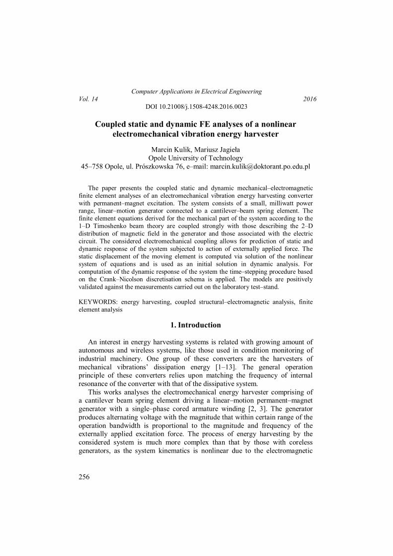
force produced by the generator [2]. This force has the two components, namely the cogging force developed by interaction of magnets' magnetic field with cored armature, and the mutual force developed by interaction of magnets' magnetic field with current of the armature winding. a)
b)
c)
Fig. 1. View of the considered system: a) overall schema, b) side view with dimensions, c) dimensions of the magnetic circuit parts
The nonlinearity is brought mainly by the cogging component. As a
consequence the system becomes a nonlinear oscillator whose resonance frequency depends on the magnitude of displacement in approximately the following way
M. Kulik, M. Jagieła / Coupled static and dynamic FE analyses ...
258
2nr A (1)
where n is the natural frequency attributed to internal mechanical structure of the system, and the coefficient which, depending on the variation of the cogging force, can be positive or negative [4], and A the magnitude of displacement. This phenomenon allows for construction of the energy harvesters whose frequency bandwidth is several Hz wide [5, 6].
There are numerous publications on the analysis of nonlinear oscillators used in energy harvesting systems [7]. The most common approach to determination of the mechanical response of these systems use the lumped–parameter models based on solution of the Duffing equation [4, 8, 9]. However, main parts of the considered system (see Fig. 1), namely the cantilever–beam spring and the linear–motion generator, are the distributed–parameter systems coupled not only through the cogging force, but also through the electromagnetic force involving the armature reaction field. The latter cannot be simply accounted for in the analysis based on the lumped–parameter model due to a nonlinear ferromagnetic core existing in the system.
In the presented approach to modeling dynamics of the considered system, the equation of motion, derived via the 1–D cantilever–beam theory, is coupled with that for the magnetic field through the electromagnetic forces and mechanical displacement. The interpolation procedures and the time–discretization schema are used to account for motion of the moving regions (yokes with magnets) in the magnetic field analysis. In order to determine the initial conditions for the dynamic model excited by the externally applied force, the coupled static model is also developed.
2. Coupled models
2.1 Dynamic model
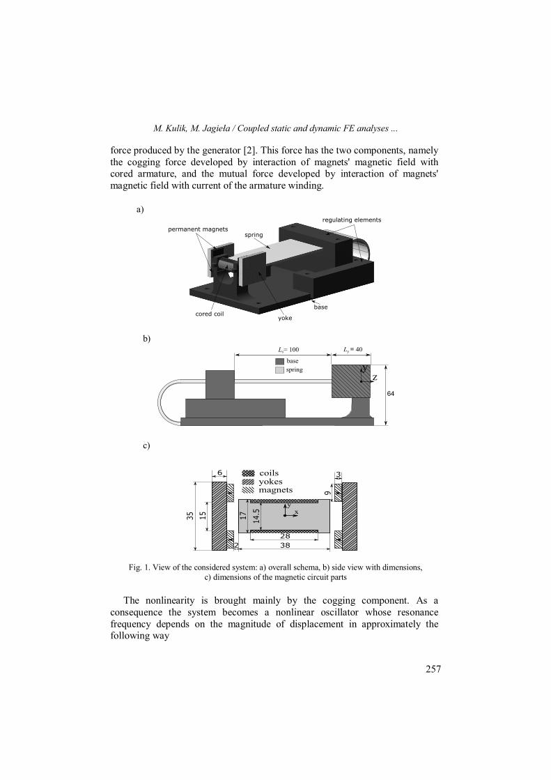
Main assumption in the considered analyses is that the 3–d effects involving
a non–straight–line trajectory of motion of the mover (yokes with magnets in Fig. 1c) can be ignored in the magnetic field analysis. This assumption is, however not too far from real condition which is illustrated in Fig. 2 by the preliminary results of simulation of the real trajectory of some particular points attached to the moving element.
As shown in figures for the magnitude of displacement being equal to a few (2 to 3) millimeters, the deviation of the trajectories from a straight line does not exceed six per cent of the translational magnitude. This is when the shaded rectangular areas that represent permanent magnets in Fig. 2a, intersect the shaded square area representing the core. In such the case results of the magnetic field analysis will not be significantly affected by the 3–d effects.
M. Kulik, M. Jagieła / Coupled static and dynamic FE analyses ...
259
Fig. 2. Illustration of motion trajectory of moving part of the generator: a) simulated deflection of spring showing relative positions of mover with respect to the armature, b) trajectories
of characteristics points attached to corners of permanent magnets in Fig. a
The finite element equation of motion of the distributed mass of spring, fixed at one end, loaded by the lumped mass (mover) derived from the Timoshenko beam theory is considered in form [14, 15]
(2) where: T
2y1y2y1y ]uu[ u is the vector of displacements containing the two translational components along the y axis, uy1 and uy2, and the
M. Kulik, M. Jagieła / Coupled static and dynamic FE analyses ...
260
two rotating components, y1 and y2, around the x axis attached to element nodes [14], M, D and K are the distributed mass, damping and stiffness matrix, respectively, while Mm is the diagonal matrix corresponding with the lumped mass of mover. In the considered approach the damping matrix is expressed via the Rayleigh damping model D = aM + bK with constants a, b to be identified. The vector Fm describes the electromagnetic force developed by the generator, dependent on the vector of displacement u, the vector of the magnetic potential and current i through the generator armature winding, while Fext the externally applied mechanical force and Fg the gravitation force.
Solution for the distribution of the magnetic potential is carried out assuming two–dimensionality of the magnetic field distribution. The finite element equation governing this distribution over plane defined by the cross–section of the generator in Fig. 1c, is considered in form [16, 17]
(3) where S is the reluctance matrix, Kw the winding function vector that distributes the current density uniformly over the coils' cross–section and takes account for sense of turns, and the vector of magnetomotive force due to permanent–magnets [16]. The current through the armature winding is calculated from equation
(4) with eff being the effective turn length, R the resistance of the winding, the load resistance, and Le the leakage inductance of the winding end connections. In order to model motion of the generator mover the interpolation sliding interface technique is used [18]. In such the case the linear constraints in the form of
0)(a jij u (5) with aij being coefficients of the first–order Lagrange interpolation polynomial, are imposed on the magnetic potentials attached to air–gap sliding interface. In such the case the equations (3) and (4) modify to
(6)
(7) with Q(u) being the transformation matrix that enforces constraints (4) on the vector such that Q(u)’ = with being the vector of nodal potentials of the constrained system. 2.2. Static model Solution of the initial–value problem defined by the equations (1), (3) and (5) must be preceded by determination of the initial conditions at time t = 0. Given the external force vector Fext0 involving the distributed mechanical force applied
M. Kulik, M. Jagieła / Coupled static and dynamic FE analyses ...
261
to the beam nodes corresponding with length of the mover at t = 0, these conditions are found assuming that current i = 0 at t = 0 and solving the following system of nonlinear equations describing the steady–state of the considered system
(8) in which the matrix CfQ’0 should be understood as to express the electromagnetic force vector Fm0 via the discrete formula describing the Maxwell stress tensor [16]. The above system of equations is solved using the fixed–point technique. 2.3. Discretisation of time in dynamic model
The initial value/algebraic problem described by equations (2)–(7) is solved considering solution of (8) by substituting in (2) du/dt with the vector of velocity and applying the Crank–Nicolson discretisation schema [16]. The obtained system of coupled difference equations has form
(9)
where t is the time–step length, and n is used as the index of a time–instant for the variables and matrices with entries that change with time. The system of equations (9) is solved starting from the initial point [u0 0 ’0 0]T. Note that unlike the rotating converters where lengths of the vectors ’n and ’n–1 are always the same, application of the sliding interface technique in the linear motion converters results in different lenght of these vectors at the two consecutive instants of time. In order to keep the dimensions of the left– and right–hand–side constant for the transition between two time–instant, the system of equations (9) takes into account that Qn–1’n–1 = n–1, Qn’n = n as well as that QT
nn–1 = ’n.
M. Kulik, M. Jagieła / Coupled static and dynamic FE analyses ...
262
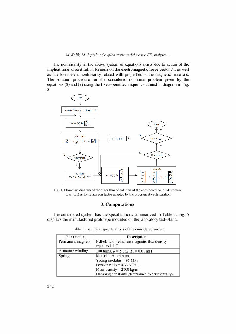
The nonlinearity in the above system of equations exists due to action of the implicit time–discretisation formula on the electromagnetic force vector Fm as well as due to inherent nonlinearity related with properties of the magnetic materials. The solution procedure for the considered nonlinear problem given by the equations (8) and (9) using the fixed–point technique is outlined in diagram in Fig. 3.
Fig. 3. Flowchart diagram of the algorithm of solution of the considered coupled problem, (0,1) is the relaxation factor adapted by the program at each iteration
3. Computations
The considered system has the specifications summarized in Table 1. Fig. 5
displays the manufactured prototype mounted on the laboratory test–stand.
Table 1. Technical specifications of the considered system
Parameter Description Permanent magnets NdFeB with remanent magnetic flux density
equal to 1.1 T. Armature winding 100 turns, R = 5.7 , Le = 0.01 mH Spring Material: Aluminum,
Young modulus = 96 MPa Poisson ratio = 0.33 MPa Mass density = 2800 kg/m3
Damping constants (determined experimentally)
M. Kulik, M. Jagieła / Coupled static and dynamic FE analyses ...
263
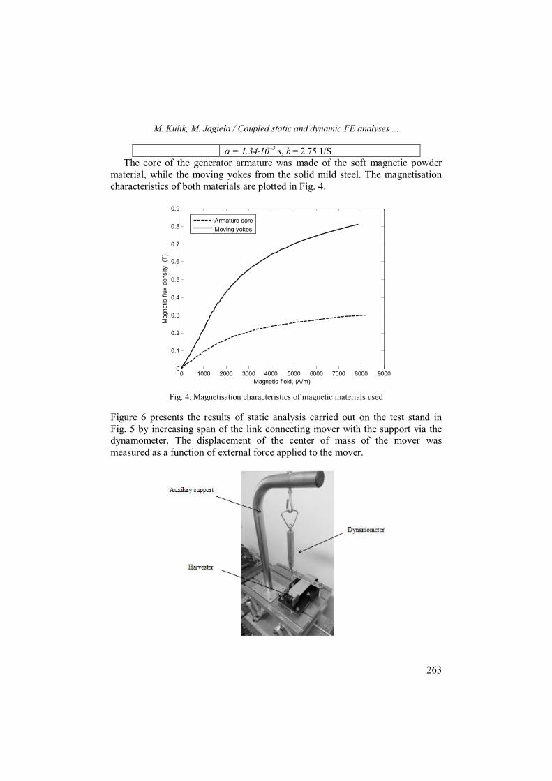
= 1.3410–5 s, b = 2.75 1/S The core of the generator armature was made of the soft magnetic powder
material, while the moving yokes from the solid mild steel. The magnetisation characteristics of both materials are plotted in Fig. 4.
0 1000 2000 3000 4000 5000 6000 7000 8000 90000
0.1
0.2
0.3
0.4
0.5
0.6
0.7
0.8
0.9
Magnetic field, (A/m)
Mag
netic
flux
den
sity
, (T)
Armature coreMoving yokes
Fig. 4. Magnetisation characteristics of magnetic materials used
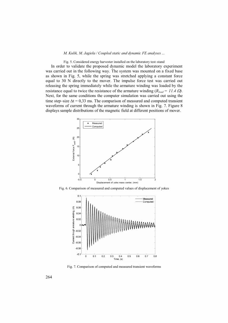
Figure 6 presents the results of static analysis carried out on the test stand in Fig. 5 by increasing span of the link connecting mover with the support via the dynamometer. The displacement of the center of mass of the mover was measured as a function of external force applied to the mover.
M. Kulik, M. Jagieła / Coupled static and dynamic FE analyses ...
264
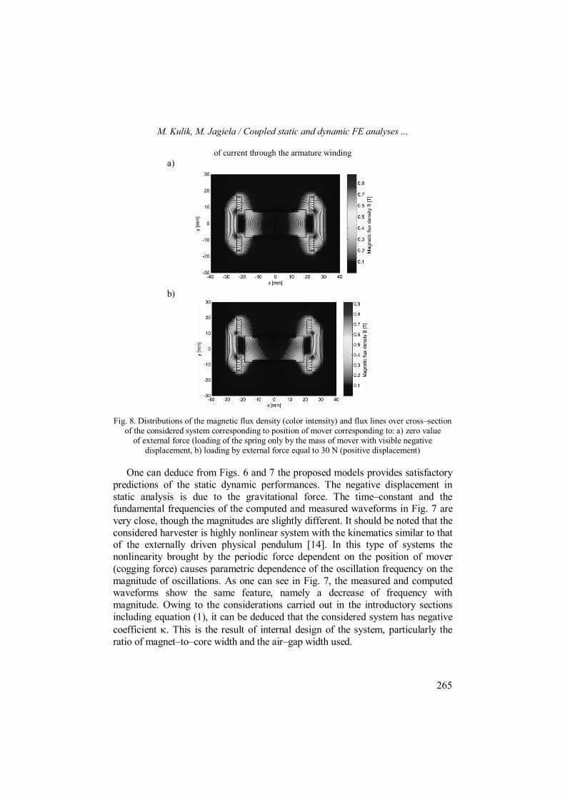
Fig. 5. Considered energy harvester installed on the laboratory test–stand In order to validate the proposed dynamic model the laboratory experiment
was carried out in the following way. The system was mounted on a fixed base as shown in Fig. 5, while the spring was stretched applying a constant force equal to 30 N directly to the mover. The impulse force test was carried out releasing the spring immediately while the armature winding was loaded by the resistance equal to twice the resistance of the armature winding (Rload = 11.4 ). Next, for the same conditions the computer simulation was carried out using the time step–size t = 0,33 ms. The comparison of measured and computed transient waveforms of current through the armature winding is shown in Fig. 7. Figure 8 displays sample distributions of the magnetic field at different positions of mover.
-0.5 0 0.5 1 1.5 2
0
5
10
15
20
25
30
Ext
erna
l for
ce F
ext0
, (N
)
Displacement of yoke mass center, (mm)
MeasuredComputed
Fig. 6. Comparison of measured and computed values of displacement of yokes
Fig. 7. Comparison of computed and measured transient waveforms
M. Kulik, M. Jagieła / Coupled static and dynamic FE analyses ...
265
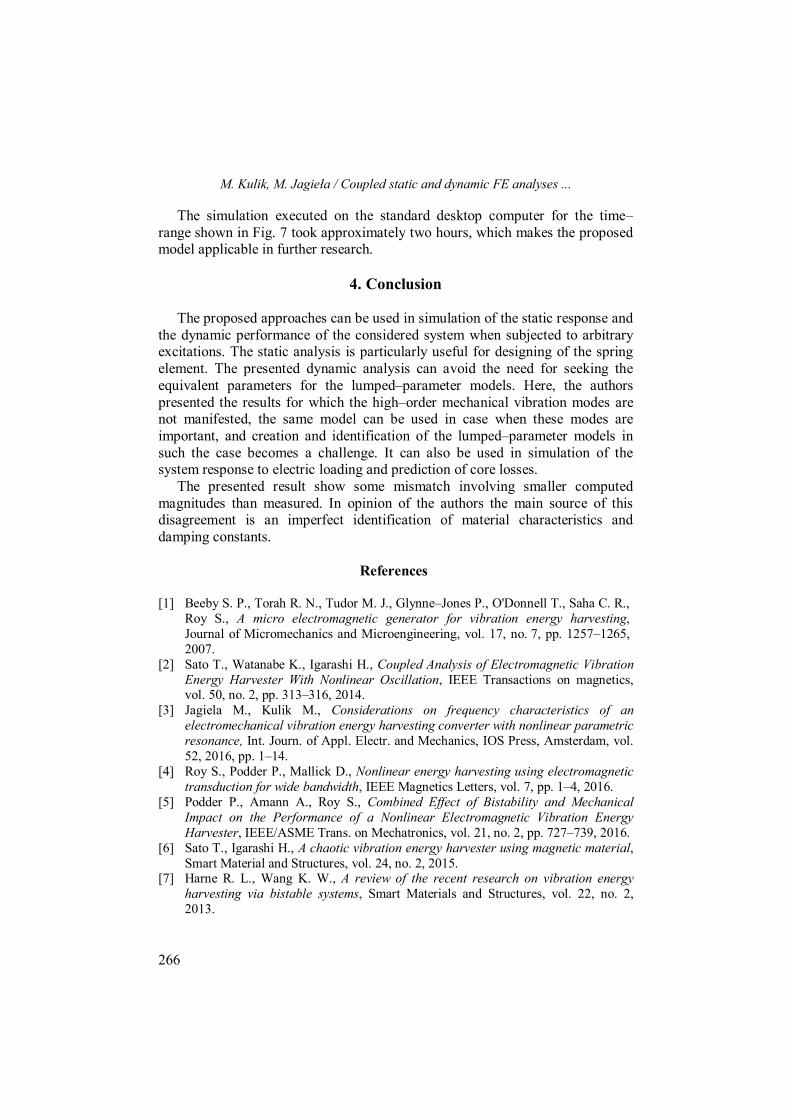
of current through the armature winding a)
b)
Fig. 8. Distributions of the magnetic flux density (color intensity) and flux lines over cross–section of the considered system corresponding to position of mover corresponding to: a) zero value
of external force (loading of the spring only by the mass of mover with visible negative displacement, b) loading by external force equal to 30 N (positive displacement)
One can deduce from Figs. 6 and 7 the proposed models provides satisfactory predictions of the static dynamic performances. The negative displacement in static analysis is due to the gravitational force. The time–constant and the fundamental frequencies of the computed and measured waveforms in Fig. 7 are very close, though the magnitudes are slightly different. It should be noted that the considered harvester is highly nonlinear system with the kinematics similar to that of the externally driven physical pendulum [14]. In this type of systems the nonlinearity brought by the periodic force dependent on the position of mover (cogging force) causes parametric dependence of the oscillation frequency on the magnitude of oscillations. As one can see in Fig. 7, the measured and computed waveforms show the same feature, namely a decrease of frequency with magnitude. Owing to the considerations carried out in the introductory sections including equation (1), it can be deduced that the considered system has negative coefficient . This is the result of internal design of the system, particularly the ratio of magnet–to–core width and the air–gap width used.
M. Kulik, M. Jagieła / Coupled static and dynamic FE analyses ...
266
The simulation executed on the standard desktop computer for the time–range shown in Fig. 7 took approximately two hours, which makes the proposed model applicable in further research.
4. Conclusion
The proposed approaches can be used in simulation of the static response and
the dynamic performance of the considered system when subjected to arbitrary excitations. The static analysis is particularly useful for designing of the spring element. The presented dynamic analysis can avoid the need for seeking the equivalent parameters for the lumped–parameter models. Here, the authors presented the results for which the high–order mechanical vibration modes are not manifested, the same model can be used in case when these modes are important, and creation and identification of the lumped–parameter models in such the case becomes a challenge. It can also be used in simulation of the system response to electric loading and prediction of core losses.
The presented result show some mismatch involving smaller computed magnitudes than measured. In opinion of the authors the main source of this disagreement is an imperfect identification of material characteristics and damping constants.
References [1] Beeby S. P., Torah R. N., Tudor M. J., Glynne–Jones P., O'Donnell T., Saha C. R.,
Roy S., A micro electromagnetic generator for vibration energy harvesting, Journal of Micromechanics and Microengineering, vol. 17, no. 7, pp. 1257–1265, 2007.
[2] Sato T., Watanabe K., Igarashi H., Coupled Analysis of Electromagnetic Vibration Energy Harvester With Nonlinear Oscillation, IEEE Transactions on magnetics, vol. 50, no. 2, pp. 313–316, 2014.
[3] Jagiela M., Kulik M., Considerations on frequency characteristics of an electromechanical vibration energy harvesting converter with nonlinear parametric resonance, Int. Journ. of Appl. Electr. and Mechanics, IOS Press, Amsterdam, vol. 52, 2016, pp. 1–14.
[4] Roy S., Podder P., Mallick D., Nonlinear energy harvesting using electromagnetic transduction for wide bandwidth, IEEE Magnetics Letters, vol. 7, pp. 1–4, 2016.
[5] Podder P., Amann A., Roy S., Combined Effect of Bistability and Mechanical Impact on the Performance of a Nonlinear Electromagnetic Vibration Energy Harvester, IEEE/ASME Trans. on Mechatronics, vol. 21, no. 2, pp. 727–739, 2016.
[6] Sato T., Igarashi H., A chaotic vibration energy harvester using magnetic material, Smart Material and Structures, vol. 24, no. 2, 2015.
[7] Harne R. L., Wang K. W., A review of the recent research on vibration energy harvesting via bistable systems, Smart Materials and Structures, vol. 22, no. 2, 2013.
M. Kulik, M. Jagieła / Coupled static and dynamic FE analyses ...
267
[8] Barton D. A. W., Burrow S. G., Clare L. R., Energy Harvesting from Vibrations with a Nonlinear Oscillator, Journal of Vibration and Acoustics, vol. 132, no. 2, 2010.
[9] Nguyen C. H., Halvorsen E., Harmonic–balance analysis of nonlinear energy harvester models, IEEE Int. Symp. on Circuits and Systems, Melbourne, pp. 2608–2611, 2014.
[10] Rahman M. F. A., Kok S. L., Ali N. M., Hamzah R. A., Aziz K. A. A., Hybrid Vibration Energy Harvester Based On Piezoelectric and Electromagnetic Transduction Mechanism, IEEE Conf. Clean Energy and Technology, pp. 243–247, 2013.
[11] Lee J., Yoon S.W., Optimization of Magnet and Back–Iron Topologies in Electromagnetic Vibration Energy Harvesters, IEEE Trans. Magn., vol. 51, no. 6, pp. 1–7, 2015.
[12] Qiu J., Wen Y., Li P., Chen H., Design and Optimization of a Tunable Magnetoelectric and Electromagnetic Hybrid Vibration–Based Generator for Wireless Sensor Networks, IEEE Trans. on magn., vol. 51, no. 11, paper no. 8203804, 2015.
[13] Liu X., Qiu J., Chen H., Xu X., Wen Y., Li P., Design and Optimization of an Electromagnetic Vibration Energy Harvester Using Dual Halbach Arrays, IEEE Trans. Magn., vol. 51, no. 11, paper no. 8204204, 2015.
[14] Ferreira A.J.M., Solid mechanics and its applications Vol. 157: Matlab codes for finite element analysis, Springer, Netherlands, 2009.
[15] Lalanne C, Mechanical Vibration and Shock, Vol. 1: Sinusiodal Vibration, Taylor & Francis, New York, 1999.
[16] Demenko A., Sykulski J.K., Network equivalents of nodal and edge elements in electromagnetics, IEEE Trans. Magn., vol. 38, no. 2, pp. 1305–1308, 2002.
[17] Demenko A., Mendrela E.A., Szelag W., Finite element analysis of saturation effects in tubular linear generator, The Int. Journ. for Comp. and Math. in Electrical and Electronic Eng. COMPEL, vol. 25, no. 1, pp. 43–54, 2006.
[18] Buffa A., Maday Y., Rapetti F., Calculation of eddy currents in moving structures by a sliding mesh–finite element method, IEEE Trans. Magn., vol. 36, pp. 1356–1359, 2000.