GL-7.16 PROJECT INFORMATION APPROVAL STAMP Project: q Approved Address: q Approved as noted Contractor: q Not approved Engineer: Remarks: Submittal Date: Notes 1: Notes 2: HIGH PRESSURE SYSTEMS FIG. 7004 with EG ® Gasket Coupling MATERIAL SPECIFICATIONS BOLTS: SAE J429, Grade 5, Zinc Electroplated ISO 898-1, Class 8.8, Zinc Electroplated followed by a Yellow Chromate Dip HEAVY HEX NUTS: ASTM A563, Grade A, Zinc Electroplated ISO 898-2, Class 8.8, Zinc Electroplated followed by a Yellow Chromate Dip STAINLESS STEEL BOLTS & NUTS: 304SS bolts and nuts are available as a standard option. (316SS are available for special order). HOUSING: Ductile Iron conforming to ASTM A 536, Grade 65-45-12. COATINGS: q Rust inhibiting paint – Color: Orange (standard) q Hot Dipped Zinc Galvanized (optional) q Other Colors Available (IE: RAL3000 and RAL9000) For other Coating requirements contact an Anvil Representative. GASKETS: Materials Properties as designated in accordance with ASTM D 2000 Grade “T” Nitrile (Orange color code) EG Gasket -20°F to 180°F (Service Temperature Range)(-29°C to 82°C) Recommended for petroleum applications. Air with oil vapors and vegetable and mineral oils. NOT FOR USE IN HOT WATER OR HOT AIR. GASKET TYPE: “EG” Style LUBRICATION: q Standard Gruvlok q Gruvlok Xtreme TM (Do Not use with Grade “L”) WORKING PRESSURE, END LOAD, PIPE END SEPARATION & DEFLECTION FROM CENTER LINE Based on standard wall steel pipe with cut or roll grooves in accordance with Gruvlok specifications. See technical data section for design factors. The Gruvlok Fig. 7004 Coupling with EG® Gasket uses the specially designed “End Guard” gasket for use with “EG” grooved pipe. The “EG” gasket has a center rib which extends between the pipes in order to provide pipe end protection, which makes it ideally suited for internally lined or coated pipe applications. The Fig. 7004 Coupling with EG® Gasket permits working pressure ratings up to 2500 psi (172.4 bar). Working Pressure and End Load values are based on “EG” cut grooved extra heavy steel pipe. Fig. 7004 provides a rigid joint and does not allow for expansion or contraction. Beveled end pipe should not be used with “EG” gaskets.
Transcript
GL-7.16
PROJECT INFORMATION APPROVAL STAMPProject: q Approved
Address: q Approved as noted
Contractor: q Not approved
Engineer: Remarks:
Submittal Date:
Notes 1:
Notes 2:
HIGH PRESSURE SYSTEMS
FIG. 7004 with EG® GasketCoupling
MATERIAL SPECIFICATIONSBOLTS:SAE J429, Grade 5, Zinc ElectroplatedISO 898-1, Class 8.8, Zinc Electroplated followed by a Yellow Chromate Dip
HEAVY HEX NUTS:ASTM A563, Grade A, Zinc ElectroplatedISO 898-2, Class 8.8, Zinc Electroplated followed by a Yellow Chromate Dip
STAINLESS STEEL BOLTS & NUTS:304SS bolts and nuts are available as a standard option.(316SS are available for special order).
HOUSING: Ductile Iron conforming to ASTM A 536, Grade 65-45-12.
COATINGS:q Rust inhibiting paint – Color: Orange (standard)q Hot Dipped Zinc Galvanized (optional)q Other Colors Available (IE: RAL3000 and RAL9000)For other Coating requirements contact an Anvil Representative.
GASKETS: Materials Properties as designated in accordance with ASTM D 2000
Grade “T” Nitrile (Orange color code) EG Gasket -20°F to 180°F (Service Temperature Range)(-29°C to 82°C) Recommended for petroleum applications. Air with oil vapors and vegetable and mineral oils. NOT FOR USE IN HOT WATER OR HOT AIR.
GASKET TYPE: “EG” Style
LUBRICATION:q Standard Gruvlokq Gruvlok XtremeTM(Do Not use with Grade “L”)
WORKING PRESSURE, END LOAD, PIPE END SEPARATION & DEFLECTION FROM CENTER LINEBased on standard wall steel pipe with cut or roll grooves in accordance with Gruvlok specifications. See technical data section for design factors.
The Gruvlok Fig. 7004 Coupling with EG® Gasket uses the specially designed “End Guard” gasket for use with “EG” grooved pipe. The “EG” gasket has a center rib which extends between the pipes in order to provide pipe end protection, which makes it ideally suited for internally lined or coated pipe applications.
The Fig. 7004 Coupling with EG® Gasket permits working pressure ratings up to 2500 psi (172.4 bar).
Working Pressure and End Load values are based on “EG” cut grooved extra heavy steel pipe. Fig. 7004 provides a rigid joint and does not allow for expansion or contraction. Beveled end pipe should not be used with “EG” gaskets.
HIGH PRESSURE SYSTEMS
FIG. 7004 with EG® GasketCoupling
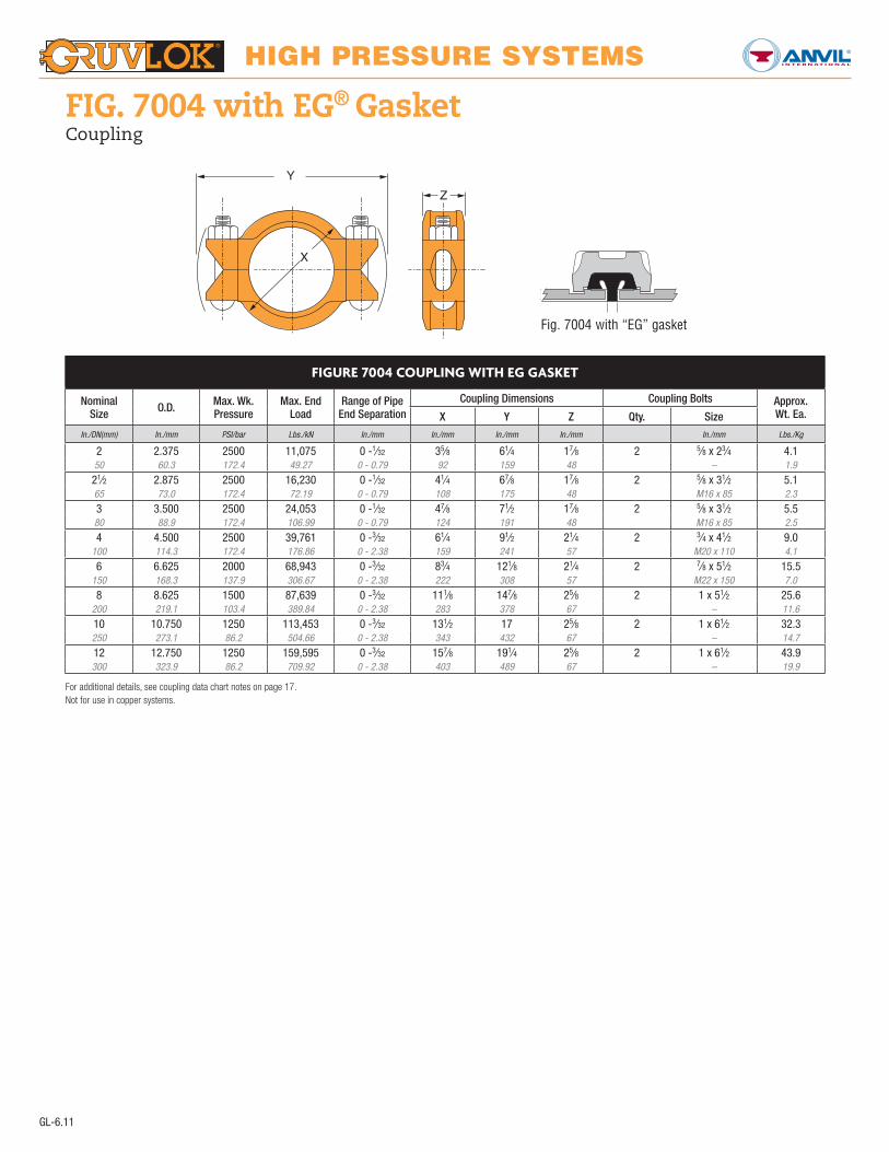
For additional details, see coupling data chart notes on page 17.Not for use in copper systems.
FIGURE 7004 COUPLING WITH EG GASKET
Nominal Size O.D. Max. Wk.
PressureMax. End
LoadRange of Pipe
End SeparationCoupling Dimensions Coupling Bolts Approx.
Wt. Ea. X Y Z Qty. SizeIn./DN(mm) In./mm PSI/bar Lbs./kN In./mm In./mm In./mm In./mm In./mm Lbs./Kg
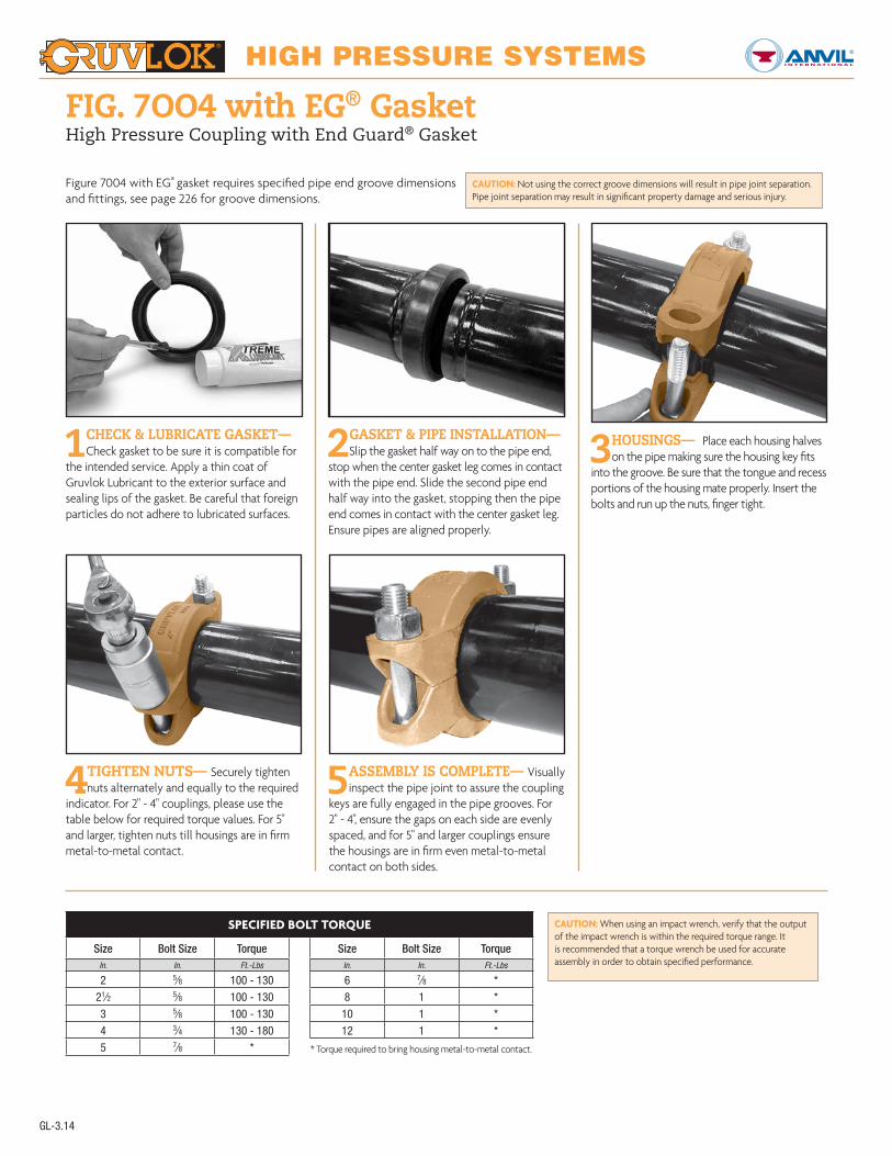
FIG. 7OO4 with EG® GasketHigh Pressure Coupling with End Guard® Gasket
1CHECK & LUBRICATE GASKET— Check gasket to be sure it is compatible for
the intended service. Apply a thin coat of Gruvlok Lubricant to the exterior surface and sealing lips of the gasket. Be careful that foreign particles do not adhere to lubricated surfaces.
2 GASKET & PIPE INSTALLATION— Slip the gasket half way on to the pipe end,
stop when the center gasket leg comes in contact with the pipe end. Slide the second pipe end half way into the gasket, stopping then the pipe end comes in contact with the center gasket leg. Ensure pipes are aligned properly.
3 HOUSINGS— Place each housing halves on the pipe making sure the housing key fits
into the groove. Be sure that the tongue and recess portions of the housing mate properly. Insert the bolts and run up the nuts, finger tight.
4 TIGHTEN NUTS— Securely tighten nuts alternately and equally to the required
indicator. For 2" - 4" couplings, please use the table below for required torque values. For 5" and larger, tighten nuts till housings are in firm metal-to-metal contact.
5 ASSEMBLY IS COMPLETE— Visually inspect the pipe joint to assure the coupling
keys are fully engaged in the pipe grooves. For 2" - 4", ensure the gaps on each side are evenly spaced, and for 5" and larger couplings ensure the housings are in firm even metal-to-metal contact on both sides.
CAUTION: When using an impact wrench, verify that the output of the impact wrench is within the required torque range. It is recommended that a torque wrench be used for accurate assembly in order to obtain specified performance.
SPECIFIED BOLT TORQUE
Size Bolt Size Torque Size Bolt Size TorqueIn. In. Ft.-Lbs In. In. Ft.-Lbs
Figure 7004 with EG® gasket requires specified pipe end groove dimensions and fittings, see page 226 for groove dimensions.
CAUTION: Not using the correct groove dimensions will result in pipe joint separation. Pipe joint separation may result in significant property damage and serious injury.