Liquid Process Piping Part 3: Miscellaneous Piping Design Course No: M02-037 Credit: 2 PDH Elie Tawil, P.E., LEED AP Continuing Education and Development, Inc. 9 Greyridge Farm Court Stony Point, NY 10980 P: (877) 322-5800 F: (877) 322-4774 [email protected]
Transcript
Liquid Process Piping Part 3: Miscellaneous Piping Design Course No: M02-037
Credit: 2 PDH
Elie Tawil, P.E., LEED AP
Continuing Education and Development, Inc. 9 Greyridge Farm Court Stony Point, NY 10980 P: (877) 322-5800 F: (877) 322-4774 [email protected]
EM 1110-1-40085 May 99
5-1
Chapter 5Plastic Piping Systems
5-1. General
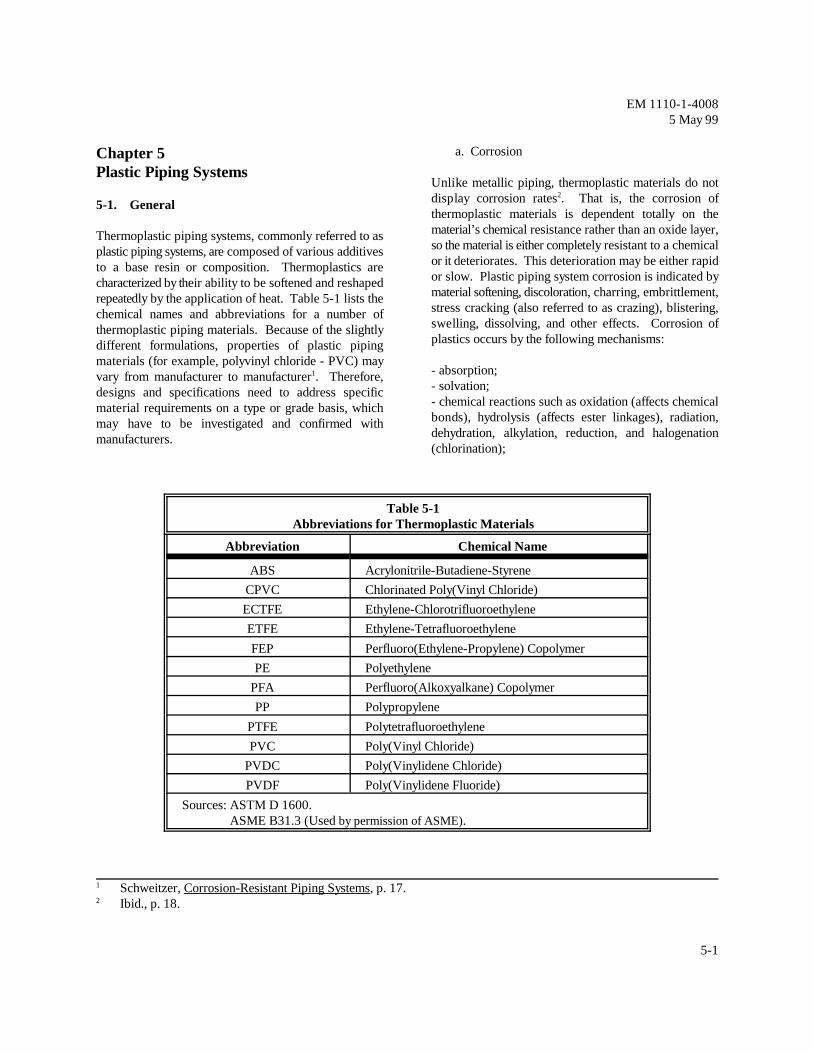
Thermoplastic piping systems, commonly referred to asplastic piping systems, are composed of various additivesto a base resin or composition. Thermoplastics arecharacterized by their ability to be softened and reshapedrepeatedly by the application of heat. Table 5-1 lists thechemical names and abbreviations for a number ofthermoplastic piping materials. Because of the slightlydifferent formulations, properties of plastic pipingmaterials (for example, polyvinyl chloride - PVC) mayvary from manufacturer to manufacturer . Therefore,1
designs and specifications need to address specificmaterial requirements on a type or grade basis, whichmay have to be investigated and confirmed withmanufacturers.
a. Corrosion
Unlike metallic piping, thermoplastic materials do notdisplay corrosion rates . That is, the corrosion of2
thermoplastic materials is dependent totally on thematerial’s chemical resistance rather than an oxide layer,so the material is either completely resistant to a chemicalor it deteriorates. This deterioration may be either rapidor slow. Plastic piping system corrosion is indicated bymaterial softening, discoloration, charring, embrittlement,stress cracking (also referred to as crazing), blistering,swelling, dissolving, and other effects. Corrosion ofplastics occurs by the following mechanisms:
- absorption;- solvation;- chemical reactions such as oxidation (affects chemicalbonds), hydrolysis (affects ester linkages), radiation,dehydration, alkylation, reduction, and halogenation(chlorination);
Table 5-1Abbreviations for Thermoplastic Materials
Sources: ASTM D 1600.ASME B31.3 (Used by permission of ASME).
Schweitzer, Corrosion-Resistant Piping Systems, p. 17.1
Ibid., p. 18.2
PR ' 2(HDS)(t/Dm)
EM 1110-1-40085 May 99
5-2
- thermal degradation which may result in eitherdepolymerization or plasticization;- environmental-stress cracking (ESC) which isessentially the same as stress-corrosion cracking inmetals; where:- UV degradation; and P = pipe pressure rating, MPa (psi)- combinations of the above mechanisms. t = minimum wall thickness, mm (in)
For plastic material compatibility with various chemicals, HDS = (HDB)(DF)see Appendix B. If reinforcing is used as part of thepiping system, the reinforcement is also a material that is The minimum pipe wall thickness can also be determinedresistant to the fluid being transported. Material selection using the requirements of ASME B31.3 as described inand compatibility review should consider the type and Paragraph 3-3b. This procedure is not directly applicableconcentration of chemicals in the liquid, liquid to thermoplastic pipe fittings, particularly in cyclictemperature, duration of contact, total stress of the piping pressure operations due to material fatigue. Therefore, itsystem, and the contact surface quality of the piping should not be assumed that thermoplastic fittings labeledsystem. See Appendix A, paragraph A-4 - Other Sources with a pipe schedule designation will have the sameof Information, for additional sources of corrosion data. pressure rating as pipe of the same designation. A good
b. Operating Pressures and Temperatures 2467 which specify pressure ratings for PVC schedule 40
The determination of maximum steady state design the rating for PVC pipe of the same designation. Forpressure and temperature is similar to that described for thermoplastic pipe fittings that do not have publishedmetallic piping systems. However, a key issue that must pressure ratings information similar to ASTM standards,be addressed relative to plastic piping systems is the the fitting manufacturer shall be consulted for fittingimpact of both minimum and maximum temperature pressure rating recommendations.limits of the materials of construction.
c. Sizing
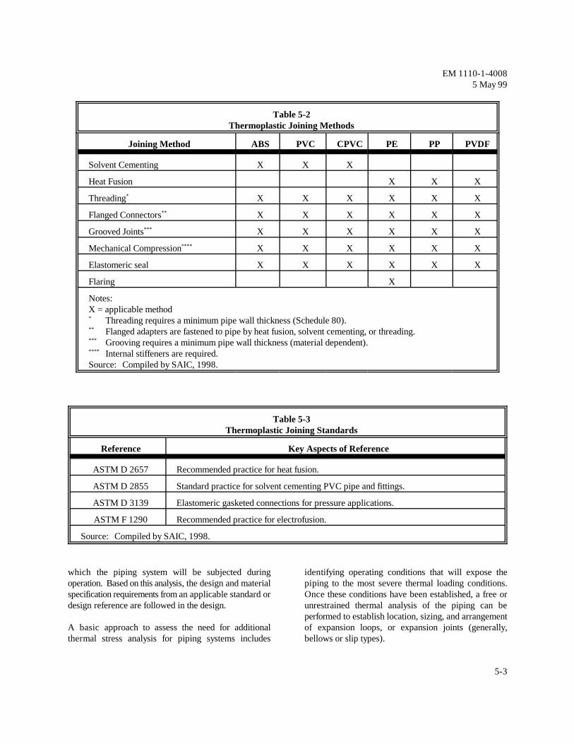
The sizing for plastic piping systems is performed for liquid process waste treatment and storage systemsconsistent with the procedures of Paragraph 3-3. are contained in Table 5-2. In selecting a joining methodHowever, one of the basic principles of designing and for liquid process piping systems, the advantages andspecifying thermoplastic piping systems for liquid disadvantages of each method are evaluated and theprocess piping pressure applications is that the short and manner by which the joining is accomplished for eachlong term strength of thermoplastic pipe decreases as the liquid service is specified. Recommended procedurestemperature of the pipe material increases. and specification for these joining methods are found in
Thermoplastic pipe is pressure rated by using the thermoplastic pipe. Table 5-3 lists applicable referencesInternational Standards Organization (ISO) rating for joining thermoplastic pipe.equation using the Hydrostatic Design Basis (HDB) ascontained in ASTM standards and Design Factors (DFs). e. Thermal ExpansionThe use of DFs is based on the specific material beingused and specific application requirements such as When designing a piping system where thermaltemperature and pressure surges. The following is the expansion of the piping is restrained at supports, anchors,basic equation for internal hydraulic pressure rating of equipment nozzles and penetrations, large thermalthermoplastic piping: stresses and loads must be analyzed and accounted for
R
D = mean diameter, mm (in)m
example of this is contained in ASTM D 2466 and D
and 80 fittings. These ratings are significantly lower than
d. Joining
Common methods for the joining of thermoplastic pipe
codes, standards and manufacturer procedures for joining
within the design. The system PFDs and P&IDs areanalyzed to determine the thermal conditions or modes to
EM 1110-1-40085 May 99
5-3
Table 5-2Thermoplastic Joining Methods
Joining Method ABS PVC CPVC PE PP PVDF
Solvent Cementing X X X
Heat Fusion X X X
Threading X X X X X X*
Flanged Connectors X X X X X X**
Grooved Joints X X X X X X***
Mechanical Compression X X X X X X****
Elastomeric seal X X X X X X
Flaring X
Notes:X = applicable method
Threading requires a minimum pipe wall thickness (Schedule 80).*
Flanged adapters are fastened to pipe by heat fusion, solvent cementing, or threading.**
Grooving requires a minimum pipe wall thickness (material dependent).***
Internal stiffeners are required.****
Source: Compiled by SAIC, 1998.
Table 5-3Thermoplastic Joining Standards
Reference Key Aspects of Reference
ASTM D 2657 Recommended practice for heat fusion.
ASTM D 2855 Standard practice for solvent cementing PVC pipe and fittings.
ASTM D 3139 Elastomeric gasketed connections for pressure applications.
ASTM F 1290 Recommended practice for electrofusion.
Source: Compiled by SAIC, 1998.
which the piping system will be subjected during identifying operating conditions that will expose theoperation. Based on this analysis, the design and material piping to the most severe thermal loading conditions.specification requirements from an applicable standard or Once these conditions have been established, a free ordesign reference are followed in the design. unrestrained thermal analysis of the piping can be
A basic approach to assess the need for additional of expansion loops, or expansion joints (generally,thermal stress analysis for piping systems includes bellows or slip types).
performed to establish location, sizing, and arrangement
L ' n1
3 E Do e
S
1/2
EM 1110-1-40085 May 99
5-4
If the application requires the use of a bellow or piston E = tensile modulus of elasticity, MPa (psi)joint, the manufacturer of the joint shall be consulted to D = pipe outer diameter, mm (in)determine design and installation requirements. e = elongation due to temperature rise, mm (in)
When expansion loops are used, the effects of bending onthe fittings used to install the expansion loop are In determining the elongation due to temperature riseconsidered. Installation of the loop should be performed information from the manufacturer on the material to bein consultation with the fitting manufacturer to ensure that used should be consulted. For example, the coefficient ofspecified fittings are capable of withstanding the expansion is 6.3 x 10 mm/mm/EC (3.4 x 10 in/in/EF)anticipated loading conditions, constant and cyclic, at the for Type IV Grade I CPVC and 5.4 x 10 mm/mm/ECdesign temperatures of the system. Terminal loadings on (2.9 x 10 in/in/EF) for Type I Grade I PVC. Otherequipment determined from this analysis can then be used sources of information on thermal expansion coefficientsto assess the equipment capabilities for withstanding the are available from plastic pipe manufacturers.loading from the piping system. It should also be notedthat this termination analysis at equipment and anchor PVC and CPVC pipe does not have the rigidity of metalterminations should consider the movement and stress pipe and can flex during expansion, especially withimpacts of the "cold" condition. smaller diameters. If expansion joints are used, axial
No rigid or restraining supports or connections should be the expansion joint, especially when maximum movementmade within the developed length of an expansion loop, of the joint is anticipated. Leakage at the seals can occuroffset, bend or brand. Concentrated loads such as valves if the pipe is cocked. Independent anchoring of the jointshould not be installed in the developed length. Piping is also recommended for positive movement of expansionsupport guides should restrict lateral movement and joints.should direct axial movement into the compensatingconfigurations. Calculated support guide spacing f. Piping Support and Burialdistances for offsets and bends should not exceedrecommended hanging support spacing for the maximum Support for thermoplastic pipe follows the same basictemperature. If that occurs, distance between anchors principles as metallic piping. Spacing of supports iswill have to be decreased until the support guide spacing crucial for plastic pipe. Plastic pipe will deflect underdistance equals or is less than the recommended support load more than metallic pipe. Excessive deflection willspacing. Use of the rule of thumb method or calculated lead to structural failure. Therefore, spacing for plasticmethod is not recommended for threaded Schedule 80 pipe is closer than for metallic pipe. Valves, meters, andconnections. Properly cemented socket cement joints fittings should be supported independently in plastic pipeshould be utilized. systems, as in metallic systems.
Expansion loops, offsets and bends should be installed as In addition, plastic pipe systems are not located nearnearly as possible at the mid point between anchors. sources of excessive heat. The nature of thermoplastic
Values for expansion joints, offsets, bends and branches increasing temperature, and hardened by decreasingcan be obtained by calculating the developed length from temperature. If the pipe is exposed to higher than designthe following equation. value ambient temperatures, the integrity of the system
where:L = developed length, m (ft) Support hangers are designed to minimize stressn = conversion factor, 10 m/mm (1/12 ft/in) concentrations in plastic pipe systems. Spacing of1
-3
o
S = maximum allowable stress, MPa (psi)
-5 -5
-5
-5
guides should be installed to ensure straight entrance into
pipe is that it is capable of being repeatedly softened by
could be compromised.
Contact with supports should be such that the plastic pipematerial is not damaged or excessively stressed. Pointcontact or sharp surfaces are avoided as they may imposeexcessive stress on the pipe or otherwise damage it.
PS '(E)(Ia)
0.149 (R)3
% deflection '100 )Y
Do
)Y '(Kx)(de)(')
[0.149(PS) % 0.061(EN)]
' '(H)(Do)(()
144' (S)(Do)
R '(Do & t)
2
Ia 't 3
12
EM 1110-1-40085 May 99
5-5
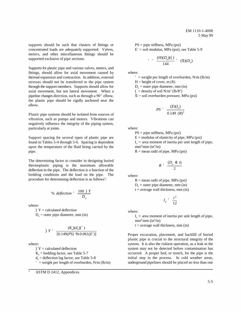
supports should be such that clusters of fittings or PS = pipe stiffness, MPa (psi)concentrated loads are adequately supported. Valves, EN = soil modulus, MPa (psi), see Table 5-9meters, and other miscellaneous fittings should besupported exclusive of pipe sections.
Supports for plastic pipe and various valves, meters, andfittings, should allow for axial movement caused bythermal expansion and contraction. In addition, externalstresses should not be transferred to the pipe systemthrough the support members. Supports should allow foraxial movement, but not lateral movement. When apipeline changes direction, such as through a 90E elbow,the plastic pipe should be rigidly anchored near theelbow.
Plastic pipe systems should be isolated from sources ofvibration, such as pumps and motors. Vibrations cannegatively influence the integrity of the piping system,particularly at joints.
Support spacing for several types of plastic pipe arefound in Tables 5-4 through 5-6. Spacing is dependentupon the temperature of the fluid being carried by thepipe.
The determining factor to consider in designing buriedthermoplastic piping is the maximum allowabledeflection in the pipe. The deflection is a function of thebedding conditions and the load on the pipe. Theprocedure for determining deflection is as follows :3
where:)Y = calculated deflectionD = outer pipe diameter, mm (in)o
where:
)Y = calculated deflectionK = bedding factor, see Table 5-7x
d = deflection lag factor, see Table 5-8e
' = weight per length of overburden, N/m (lb/in)
where:' = weight per length of overburden, N/m (lb/in)H = height of cover, m (ft)D = outer pipe diameter, mm (in)o
( = density of soil N/m (lb/ft )3 3
S = soil overburden pressure, MPa (psi)
where:PS = pipe stiffness, MPa (psi)E = modulus of elasticity of pipe, MPa (psi)I = area moment of inertia per unit length of pipe,a
mm /mm (in /in)4 4
R = mean radii of pipe, MPa (psi)
where:R = mean radii of pipe, MPa (psi)D = outer pipe diameter, mm (in)o
t = average wall thickness, mm (in)
where:I = area moment of inertia per unit length of pipe,a
mm /mm (in /in)4 4
t = average wall thickness, mm (in)
Proper excavation, placement, and backfill of buriedplastic pipe is crucial to the structural integrity of thesystem. It is also the riskiest operation, as a leak in thesystem may not be detected before contamination hasoccurred. A proper bed, or trench, for the pipe is theinitial step in the process. In cold weather areas,underground pipelines should be placed no less than one
ASTM D 2412, Appendices.3
EM 1110-1-40085 May 99
5-6
Table 5-4Support Spacing for Schedule 80 PVC Pipe
Nominal Maximum Support Spacing, m (ft) at Various TemperaturesPipe Size,mm (in) 16EC (60EF) 27EC (80EF) 38EC (100EF) 49EC (120EF) 60EC (140EF)*
Note: The above spacing values are based on test data developed by the manufacturer for the specific product andcontinuous spans. The piping is insulated and is full of liquid that has a specific gravity of 1.0.* The use of continuous supports or a change of material (e.g., to CPVC) is recommended at 60EC (140EF).
Source: Harvel Plastics, Product Bulletin 112/401 (rev. 10/1/95), p. 63.
Table 5-5Support Spacing for Schedule 80 PVDF Pipe
Nominal PipeSize, mm (in)
Maximum Support Spacing, m (ft) at Various Temperatures
Note: The above spacing values are based on test data developed by the manufacturer for the specific product andcontinuous spans. The piping is insulated and is full of liquid that has a specific gravity of 1.0.
Source: Asahi/America, Piping Systems Product Bulletin P-97/A, p. 24.
EM 1110-1-40085 May 99
5-7
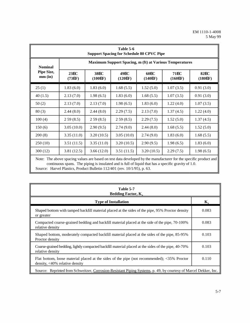
Table 5-6Support Spacing for Schedule 80 CPVC Pipe
NominalPipe Size,mm (in)
Maximum Support Spacing, m (ft) at Various Temperatures
Note: The above spacing values are based on test data developed by the manufacturer for the specific product andcontinuous spans. The piping is insulated and is full of liquid that has a specific gravity of 1.0.
Source: Harvel Plastics, Product Bulletin 112/401 (rev. 10/1/95), p. 63.
Table 5-7Bedding Factor, Kx
Type of Installation Kx
Shaped bottom with tamped backfill material placed at the sides of the pipe, 95% Proctor density 0.083or greater
Compacted coarse-grained bedding and backfill material placed at the side of the pipe, 70-100% 0.083relative density
Shaped bottom, moderately compacted backfill material placed at the sides of the pipe, 85-95% 0.103Proctor density
Coarse-grained bedding, lightly compacted backfill material placed at the sides of the pipe, 40-70% 0.103relative density
Flat bottom, loose material placed at the sides of the pipe (not recommended); <35% Proctor 0.110density, <40% relative density
Source: Reprinted from Schweitzer, Corrosion-Resistant Piping Systems, p. 49, by courtesy of Marcel Dekker, Inc.
EM 1110-1-40085 May 99
5-8
Table 5-8Deflection Lag Factor, de
Installation Condition de
Burial depth <5 ft. with moderate to high degree of compaction (85% or greater Proctor, ASTM D 698 2.0or 50% or greater relative density ASTM D-2049)
Burial depth <5 ft. with dumped or slight degree of compaction (Proctor > 85%, relative density > 40%) 1.5
Burial depth >5 ft. with moderate to high degree of compaction 1.5
Burial depth > 5 ft. with dumped or slight degree of compaction 1.25
Source: Reprinted from Schweitzer, Corrosion-Resistant Piping Systems, p. 49, by courtesy of Marcel Dekker, Inc.
Table 5-9Values of EN Modulus of Soil Reaction for Various Soils
Soil Type and Pipe BeddingMaterial
EN for Degree of Compaction of Bedding, MPa (lb/ft )2
Dumped >40% rel. den. 40-70% rel. den. >70% rel. den.
Fine-grained soils (LL >50) No data available - consult a soil engineer or use EN = 0with medium to high plasticityCH, MH, CH-MH
Fine-grained soils (LL <50) 0.35 (50) 1.38 (200) 2.76 (400) 6.90 (1000)with medium to no plasticity CL, ML, ML-CL, with <25%coarse-grained particles
Fine-grained soils (LL <50) 0.69 (100) 2.76 (400) 6.90 (1000) 13.8 (2000)with no plasticity CL, ML,ML-CL, with >25% coarse-grained particles.
Coarse-grained soils with fines 0.69 (100) 2.76 (400) 6.90 (1000) 13.8 (2000)GM, GC, SM, SC contains>12% fines.
Coarse-grained soils with little 1.38 (200) 6.90 (1000) 13.8 (2000) 20.7 (3000)or no fines GW, SW, GP, SPcontains <12% fines (or anyborderline soil beginning with GM-GC or GC-SC)
Crushed rock 6.90 (1000) 20.7 (3000) 20.7 (3000) 20.7 (3000)
Schweitzer, Corrosion-Resistant Piping Systems, p. 48, (by courtesy of Marcel Dekker, Inc.).
EM 1110-1-40085 May 99
5-9
foot below the frost line. The trench bottom should be pipes, elevated temperatures, or longer support spanrelatively flat, and smooth, with no sharp rocks that could spacing. The system is selected based upon thedamage the pipe material. The pipe should be bedded application and design calculations.with a uniformly graded material that will protect the pipeduring backfill. Typical installations use an American The ranking of PVC piping systems from highest toAssociation of State Highway Transportation Officials lowest maximum operating pressure is as follows:(AASHTO) #8 aggregate, or pea-gravel for six inches Schedule 80 pipe socket-welded; Schedule 40 pipe withbelow and above the pipe. These materials can be Schedule 80 fittings, socket-welded; and Schedule 80dumped in the trench at approximately 90-95% Proctor pipe threaded. Schedule 40 pipe provides equal pressurewithout mechanical compaction. The remainder of the rating to threaded Schedule 80, making Schedule 80trench should be backfilled with earth, or other material threaded uneconomical. In addition, the maximumappropriate for surface construction, and compacted allowable working pressure of PVC valves is lower thanaccording to the design specifications. a Schedule 80 threaded piping system.
Polyvinyl chloride (PVC) is the most widely used Polytetrafluoroethylene (PTFE) is a very commonthermoplastic piping system. PVC is stronger and more thermoplastic material used in many other applications inrigid than the other thermoplastic materials. When addition to piping systems. PTFE is chemically resistantspecifying PVC thermoplastic piping systems particular and has a relatively wide allowable temperature range ofattention must be paid to the high coefficient of -260EC (-436EF) to 260EC (500EF). Furthermore,expansion-contraction for these materials in addition to PTFE has a high impact resistance and a low coefficienteffects of temperature extremes on pressure rating, of friction and is often considered “self-lubricating.” Theviscoelasticity, tensile creep, ductility, and brittleness. most common trade name for PTFE is Teflon, registered
a. PVC Specifications
PVC pipe is available in sizes ranging from 8 to 400 mm(1/4 to 16 in), in Schedules 40 and 80. Piping shall Acrylonitrile-Butadiene-Styrene (ABS) is a thermoplasticconform to ASTM D 2464 for Schedule 80 threaded material made with virgin ABS compounds meeting thetype; ASTM D 2466 for Schedule 40 socket type; or ASTM requirements of Cell Classification 4-2-2-2-2ASTM D 2467 for Schedule 80 socket type. (pipe) and 3-2-2-2-2 (fittings). Pipe is available in both
Maximum allowable pressure ratings decrease with interchangeably. Pipe and fittings are available in size 32increasing diameter size. To maintain pressures ratings mm (1-1/4 in) through 300 mm (12 in) in diameter. Theat standard temperatures, PVC is also available in pipe can be installed above or below grade.Standard Dimension Ratio (SDR). SDR changes thedimensions of the piping in order to maintain the a. ABS Standardsmaximum allowable pressure rating.
b. PVC Installation pipe. ASTM D 2661 specifies requirements for solid
For piping larger than 100 mm (4 in) in diameter, specifies requirements for drain, waste, and vent pipe andthreaded fittings should not be used. Instead socket fittings with a cellular core. Solid wall ABS fittingswelded or flanged fittings should be specified. If a conform to ASTM D 2661. The drainage pattern forthreaded PVC piping system is used, two choices are fittings is specified by ASTM D 3311.available, either use all Schedule 80 piping and fittings,or use Schedule 40 pipe and Schedule 80 threaded ABS compounds have many different formulations thatfittings. Schedule 40 pipe will not be threaded. Schedule vary by manufacturer. The properties of the different80 pipe would be specified typically for larger diameter formulations also vary extensively. ABS shall be
trademark of E.I Dupont Company.
5-4. Acrylonitrile-Butadiene-Styrene (ABS)
solid wall and cellular core wall, which can be used
ASTM D 2282 specifies requirements for solid wall ABS
wall pipe for drain, waste, and vents. ASTM F 628
EM 1110-1-40085 May 99
5-10
specified very carefully and thoroughly because the 40 socket type. However, note that Schedule 40 socketacceptable use of one compound does not mean that all may be difficult to procure.ABS piping systems are acceptable. Similarly, ABScompositions that are designed for air or gas handlingmay not be acceptable for liquids handling.
b. ABS Limitations result of manufacturing processes. Table 5-10 lists the
Pigments are added to the ABS to make pipe and fittings weight type also exists. PE should be protected fromresistant to ultraviolet (UV) radiation degradation. Pipe ultraviolet radiation by the addition of carbon black as aand fittings specified for buried installations may be stabilizer; other types of stabilizers do not protectexposed to sunlight during construction, however, and adequately . PE piping systems are available in sizesprolonged exposure is not advised. ranging from 15 to 750 mm (½ to 30 in). Like PVC, PE
ABS pipe and fittings are combustible materials; maximum allowable pressure ratings.however, they may be installed in noncombustiblebuildings. Most building codes have determined thatABS must be protected at penetrations of walls, floors,ceilings, and fire resistance rated assemblies. The Polypropylene (PP) piping materials are similar to PE,method of protecting the pipe penetration is using a containing no chlorine or fluorine. PP piping systems arethrough-penetration protection assembly that has been available in Schedule 40, Schedule 80, and SDRtested and rated in accordance with ASTM E 814. The dimensions. With a specific gravity of 0.91, PP pipingimportant rating is the "F" rating for the through systems are one of the lightest thermoplastic pipingpenetration protection assembly. The "F" rating must be systems. a minimum of the hourly rating of the fire resistance ratedassembly that the ABS plastic pipe penetrates. Localcode interpretations related to through penetrations areverified with the jurisdiction having authority. Polyvinylidene fluoride (PVDF) pipe is available in a
5-5. Chlorinated Polyvinyl Chloride (CPVC)
Chlorinated polyvinyl chloride (CPVC) is more highly above 49EC (120EF) requires continuous support. Carechlorinated than PVC. CPVC is commonly used for must be taken in using PVDF piping under suction.chemical or corrosive services and hot water above 60EC PVDF does not degrade in sunlight; therefore, PVDF(140EF) and up to 99EC (210EF). CPVC is does not require UV stabilizers or antioxidants. PVDFcommercially available in sizes of 8 to 300 mm (1/4 to 12 pipe is chemically resistant to most acids; bases andin) for Schedule 40 and Schedule 80. Exposed CPVC organics; and can transport liquid or powdered halogenspiping should not be pneumatically tested, at any such as chlorine or bromine. PVDF should not be usedpressure, due to the possibility of personal injury from with strong alkalies, fuming acids, polar solvents, amines,fragments in the event of pipe failure; see Paragraph 3-8d ketones or esters . Trade names for PVDF pipe includefor further information. Kynar by Elf Atochem, Solef by Solvay, Hylar by
ASTM specifications for CPVC include: ASTM F 437for Schedule 80 threaded type; ASTM F 439 for Fusion welding is the preferred method for joining PVDFSchedule 80 socket type; and ASTM F 438 for Schedule pipe. Threading can only be accomplished on Schedule
5-6. Polyethylene (PE)
Polyethylene (PE) piping material properties vary as a
common types of PE, although an ultra high molecular
4
piping is available in SDR dimensions to maintain
5-7. Polypropylene (PP)
5-8. Polyvinylidene Fluoride (PVDF)
diameter range of 15 to 150 mm (½ to 6 in); Schedules40 and 80; and pressure ratings of 1.03 MPa (150 psig)and 1.59 MPa (230 psig). Use of PVDF with liquids
5
Ausimont USA, and Super Pro 230 by Asahi America.
80 pipe.
Schweitzer, Corrosion-Resistant Piping System, p. 39.4
Ibid., p. 43.5
EM 1110-1-40085 May 99
5-11
Table 5-10Polyethylene Designations
Type Standard Specific Gravity
Low Density (LDPE) ASTM D 3350, Type I 0.91 to 0.925
Medium Density (MDPE) ASTM D 3350, Type II 0.926 to 0.940
High Density (HDPE) ASTM D 3350, Type III 0.941 to 0.959and ASTM D 1248 Type IV
Source: Compiled by SAIC, 1998
EM 1110-1-40085 May 99
6-1
Chapter 6Rubber and Elastomer Piping Systems
6-1. General
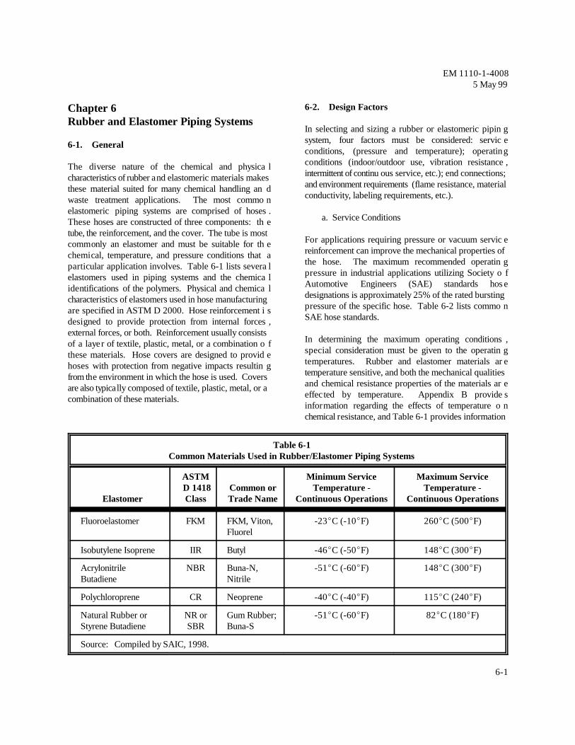
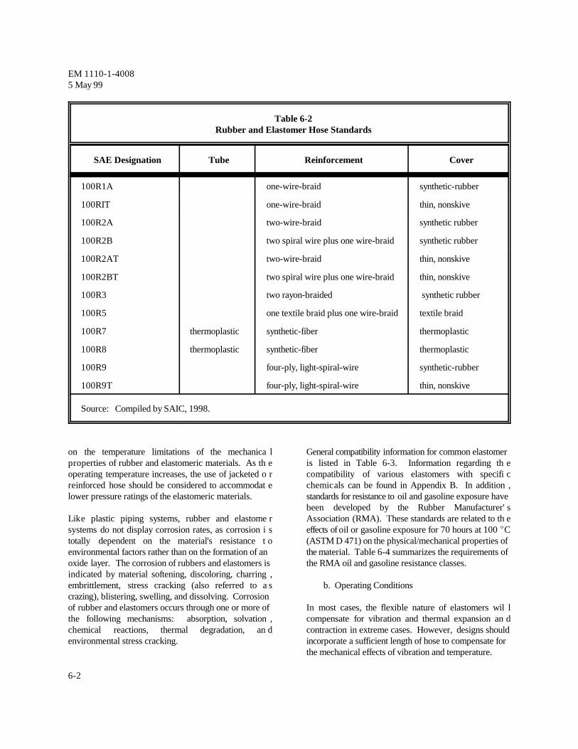
The diverse nature of the chemical and physica lcharacteristics of rubber and elastomeric materials makesthese material suited for many chemical handling an dwaste treatment applications. The most commo nelastomeric piping systems are comprised of hoses .These hoses are constructed of three components: th etube, the reinforcement, and the cover. The tube is mostcommonly an elastomer and must be suitable for th echemical, temperature, and pressure conditions that aparticular application involves. Table 6-1 lists severa lelastomers used in piping systems and the chemica lidentifications of the polymers. Physical and chemica lcharacteristics of elastomers used in hose manufacturingare specified in ASTM D 2000. Hose reinforcement i sdesigned to provide protection from internal forces ,external forces, or both. Reinforcement usually consistsof a layer of textile, plastic, metal, or a combination o fthese materials. Hose covers are designed to provid ehoses with protection from negative impacts resultin gfrom the environment in which the hose is used. Coversare also typically composed of textile, plastic, metal, or acombination of these materials.
6-2. Design Factors
In selecting and sizing a rubber or elastomeric pipin gsystem, four factors must be considered: servic econditions, (pressure and temperature); operatin gconditions (indoor/outdoor use, vibration resistance ,intermittent of continu ous service, etc.); end connections;and environment requirements (flame resistance, materialconductivity, labeling requirements, etc.).
a. Service Conditions
For applications requiring pressure or vacuum servic ereinforcement can improve the mechanical properties ofthe hose. The maximum recommended operatin gpressure in industrial applications utilizing Society o fAutomotive Engineers (SAE) standards hos edesignations is approximately 25% of the rated burstingpressure of the specific hose. Table 6-2 lists commo nSAE hose standards.
In determining the maximum operating conditions ,special consideration must be given to the operatin gtemperatures. Rubber and elastomer materials ar etemperature sensitive, and both the mechanical qualitiesand chemical resistance properties of the materials ar eeffec ted by temperature. Appendix B provide sinformation regarding the effects of temperature o nchemical resistance, and Table 6-1 provides information
Table 6-1Common Materials Used in Rubber/Elastomer Piping Systems
Elastomer Class Trade Name Continuous Operations Continuous Operations
ASTM Minimum Service Maximum Service D 1418 Common or Temperature - Temperature -
on the temperature limitations of the mechanica l General compatibility information for common elastomerproperties of rubber and elastomeric materials. As th e is listed in Table 6-3. Information regarding th eoperating temperature increases, the use of jacketed o r compatibility of various elastomers with specifi creinforced hose should be considered to accommodat e chemicals can be found in Appendix B. In addition ,lower pressure ratings of the elastomeric materials. standards for resistance to oil and gasoline exposure have
Like plastic piping systems, rubber and elastome r Association (RMA). These standards are related to th esystems do not display corrosion rates, as corrosion i s effects of oil or gasoline exposure for 70 hours at 100 ECtotally dependent on the material's resistance t o (ASTM D 471) on the physical/mechanical properties ofenvironmental factors rather than on the formation of an the material. Table 6-4 summarizes the requirements ofoxide layer. The corrosion of rubbers and elastomers is the RMA oil and gasoline resistance classes.indicated by material softening, discoloring, charring ,embrittlement, stress cracking (also referred to a s b. Operating Conditionscrazing), blistering, swelling, and dissolving. Corrosionof rubber and elastomers occurs through one or more of In most cases, the flexible nature of elastomers wil lthe following mechanisms: absorption, solvation , compensate for vibration and thermal expansion an dchemical reactions, thermal degradation, an d contraction in extreme cases. However, designs shouldenvironmental stress cracking. incorporate a sufficient length of hose to compensate for
been developed by the Rubber Manufacturer' s
the mechanical effects of vibration and temperature.
EM 1110-1-40085 May 99
6-3
Table 6-3General Chemical Compatibility Characteristics of Common Elastomers
Isobutylene Isoprene Dilute mineral acids, Hydrocarbons and oils, most solvents,alkalies, some concentrated nitric and sulfuric acidsconcentrated acids,oxygenated solvents
Natural Rubber or Styrene Butadiene Non-oxidizing acids, Hydrocarbons, oils, and oxidizing agentsalkalies, and salts
Notes: See Appendix B for more chemical resistance information.Source: Compiled by SAIC, 1998.
Table 6-4RMA Oil and Gasoline Resistance Classifications
RMA Designation Maximum Volume Change Tensile Strength Retained
Class A (High oil resistance) +25% 80%
Class B (Medium-High oil resistance) +65% 50%
Class C (Medium oil resistance) +100% 40%
Source: RMA, "The 1996 Hose Handbook," IP-2, p. 52.
EM 1110-1-40085 May 99
6-4
c. End Connections hose is designated as conducting or nonconducting, th e
Hose couplings are used to connect hoses to a proces s currently exist for the prevention and safe dissipation ofdischarge or input point. Meth ods for joining elastomeric static charge from hoses. Methods used to contro lhose include banding/clamping, flanged joints, an d electrical properties include designing contact between athreaded and mechanical coupling systems. Thes e body reinforcing wire and a metal coupling to provid emethods are typically divided into reusable and non - electrical continuity for the hose or using a conductiv ereusable couplings. Table 6-5 lists common types o f hose cover. ASTM D 380 describes standard tes tcouplings for hoses. Selection of the proper couplin g methods for the conductivity of elastomeric hoses. For ashould take into account the operating conditions an d hose to be considered non-conductive, it should be testedprocedures that will be employed. using these methods.
d. Environmental Requirements
Hose is also manufactured with conductive, non - The primary considerations in determining the minimumconductive, and uncontrolled electrical properties . acceptable diameter of any elastomeric hose are desig nCritical applications such as transferring aircraft hose or flow rate and pressure drop. The design flow rate i stransferring liquids aro und high-voltage lines, require the based on system demands that a re normally established inelectrical properties of hose to be controlled. Unless the the process design phase of a proje ct and which should be
electrical properties are uncontrolled. Standards do not
6-3. Sizing
Table 6-5Typical Hose Couplings
Class Description
Reusable with clamps 1. Short Shank Coupling2. Long Shank Coupling3. Interlocking Type4. Compression Ring Type
Reusable without clamps 1. Screw Type2. Push-on Type
fully defined by this stage of the system design. Pressuredrop through the elastomeric hose must be designed t oprovide an optimum balance between installed costs and Isobutylene isoprene (Butyl or II R) has excellent abrasionoperating costs. Primary factors that will impact thes e resistance and excellent flexing properties. Thes ecosts and system operating performance are interna l characteristics combine to give isobutylene isoprene verydiameter (and the resulting fluid velocity), materials o f good weathering and aging resistance. Isobutylen econstruction and length of hose. isoprene is impermeable to most gases, but provides poor
6-4. Piping Support and Burial
Support for rubber and elastomer piping systems shouldfollow similar principles as metallic and plastic pipe .However, continuous pi ping support is recommended for Acrylonitrile butadiene (nitrile, Buna-N or NBR) offersmost applications due to the flexible nature of thes e excellent resistance to petroleum oils, aromati cmaterials. Also due to its flexible nature, elastome r hydrocarbons and many acids. NBR also has goo dpiping is not used in buried service because the piping is elongation properties. However, NBR does not provideunable to support the loads required for buried service. good resistance to weathering.
When routing elastomer hose, change in piping directioncan be achieved through bending the hose rather tha nusing fittings. When designing a rubber or elastome r Polychloroprene (neoprene or CR) is one of the oldes tpiping system, it is important to make sure that the bend synthetic rubbers. It is a good all-purpose elastomer thatradius used does not exceed the max imum bend radius for is resistant to ozone, ultraviolet radiation, and oxidation.the hose used. If the maximum bend radius is exceeded, Neoprene is also heat and flame resistant. Thes ethe hose may collapse and constricted flow or materia l characteristics give neoprene excel lent resistance to agingfailure could occur. As a rule of thumb, the bend radius and weathering. Neoprene also provides good chemicalshould be six times the diameter of a hard wall hose o r resistance to many petroleum based products an dtwelve times the diameter of a soft wall hose. aliphatic hydrocarbons. However, neoprene is vulnerable
6-5. Fluoroelastomer
Fluoroelastomer (FKM) is a class of materials whic hincludes several fluoropolymers used for hose products.Trade names of these materials incl ude Viton and Fluorel. Natural rubber (styrene butadiene, gum rubber, Buna-S,Fluoroelastomers provide excellent high temperatur e NR, or SBR) has high resilience, good tear resistance ,resistance, with the maximum allowable operatin g and good tensile strength. I t also exhibits wear resistancetemperatures for fluoroelastomer varying from 232 t o and is flexible at low te mperatures. These characteristics315EC (450 to 600EF), depending upon th e make natural rubber suitable for general service outdoormanufacturer. Fluoroelastomers also provide very good use. However, natural rubber is not flame resistant andchemical resistance to a wide variety of chemical classes. does not provide resistance to petroleum based fluids.
6-6. Isobutylene Isoprene
resistance to petroleum based fluids. Isobutylen eisoprene is also not flame resistant.
6-7. Acrylonitrile Butadiene
6-8. Polychloroprene
to chlorinated solvents, polar s olvents, and strong mineralacids.
6-9. Natural Rubber
EM 1110-1-40085 May 99
7-1
Chapter 7Thermoset Piping Systems
7-1. General
Thermoset piping systems are composed of plasticmaterials and are identified by being permanently set,cured or hardened into shape during the manufacturingprocess. Thermoset piping system materials are acombination of resins and reinforcing. The four primarythermoset resins are epoxies, vinyl esters, polyesters, andfurans. Other resins are available.
a. Thermoset Piping Characteristics
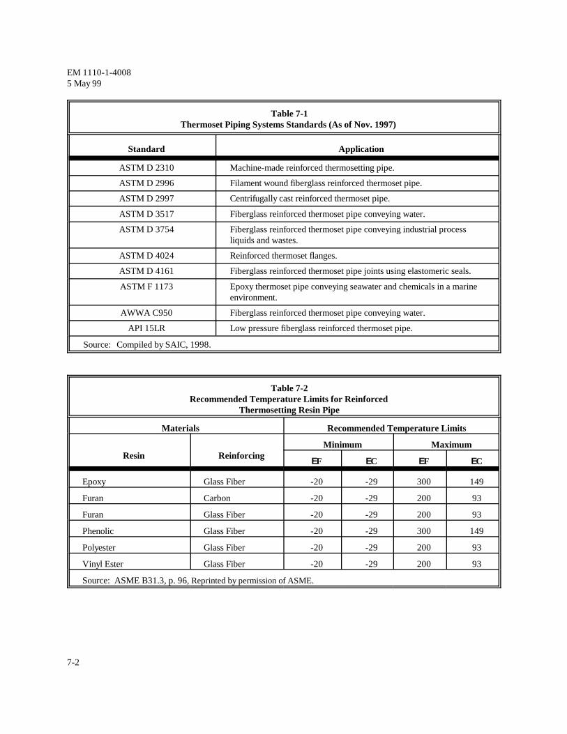
Advantages of thermoset piping systems are a highstrength-to-weight ratio; low installation costs; ease ofrepair and maintenance; hydraulic smoothness with atypical surface roughness of 0.005 mm (0.0002 in);flexibility, since low axial modulus of elasticity allowslightweight restraints and reduces the need for expansionloops; and low thermal and electrical conductivity.Disadvantages of thermoset piping systems are lowtemperature limits; vulnerability to impact failure;increased support requirements, a drawback of the lowmodulus of elasticity; lack of dimensional standardsincluding joints since pipe, fittings, joints and adhesivesare generally not interchangeable between manufacturers;and susceptibility to movement with pressure surges,such as water hammer. Table 7-1 lists applicablestandards for thermoset piping systems.
b. Corrosion Resistance
Like other plastic materials, thermoset piping systemsprovide both internal and external corrosion resistance.For compatibility of thermoset plastic material withvarious chemicals, see Appendix B. Due to the differentformulations of the resin groups, manufacturers arecontacted to confirm material compatibility. Forapplications that have limited data relating liquid servicesand resins, ASTM C 581 provides a procedure toevaluate the chemical resistance of thermosetting resins.
c. Materials of Construction
Fiberglass is the most common reinforcing material usedin thermoset piping systems because of its low cost, hightensile strength, light weight and good corrosion
resistance. Other types of commercially availablereinforcement include graphite fibers for use withfluorinated chemicals such as hydrofluoric acid; aramid;polyester; and polyethylene. The types of fiberglass usedare E-glass; S-glass for higher temperature and tensilestrength requirements; and C-glass for extremelycorrosive applications.
Most thermoset piping systems are manufactured using afilament winding process for adding reinforcement. Thisprocess accurately orients and uniformly places tensionon the reinforcing fibers for use in pressure applications.It also provides the best strength-to-weight ratio ascompared to other production methods. The other mainmethod of manufacturing is centrifugal casting,particularly using the more reactive resins.
Thermoset piping can be provided with a resin-rich layer(liner) to protect the reinforcing fibers. The use of linersis recommended for chemical and corrosive applications.Liners for filament wound pipe generally range inthickness from 0.25 to 1.25 mm (0.01 to 0.05 in), but canbe custom fabricated as thick as 2.8 mm (0.110 in) andare often reinforced. Liner thickness for centrifugally castthermoset piping generally ranges from 1.25 to 2.0 mm(0.05 to 0.08 in); these liners are not reinforced. If notreinforced, liners may become brittle when exposed tolow temperatures. Impacts or harsh abrasion may causefailure under these conditions.
Fittings are manufactured using compression molding,filament winding, spray-up, contact molding and miteredprocesses. Compression molding is typically used forsmaller diameter fittings, and filament winding is usedfor larger, 200 to 400 mm (8 to 16 in), fittings. Thespray-up, contact molding and mitered processes are usedfor complex or custom fittings. The mitered process istypically used for on-site modifications.
d. Operating Pressures and Temperatures
Loads; service conditions; materials; design codes andstandards; and system operational pressures andtemperatures are established as described in Chapters 2and 3 for plastic piping systems. Table 7-2 listsrecommended temperature limits for reinforcedthermosetting resin pipe.
EM 1110-1-40085 May 99
7-2
Table 7-1Thermoset Piping Systems Standards (As of Nov. 1997)
Standard Application
ASTM D 2310 Machine-made reinforced thermosetting pipe.
ASTM D 2996 Filament wound fiberglass reinforced thermoset pipe.
ASTM D 2997 Centrifugally cast reinforced thermoset pipe.
ASTM D 3517 Fiberglass reinforced thermoset pipe conveying water.
ASTM D 3754 Fiberglass reinforced thermoset pipe conveying industrial processliquids and wastes.
ASTM D 4024 Reinforced thermoset flanges.
ASTM D 4161 Fiberglass reinforced thermoset pipe joints using elastomeric seals.
ASTM F 1173 Epoxy thermoset pipe conveying seawater and chemicals in a marineenvironment.
API 15LR Low pressure fiberglass reinforced thermoset pipe.
Source: Compiled by SAIC, 1998.
Table 7-2Recommended Temperature Limits for Reinforced
Thermosetting Resin Pipe
Materials Recommended Temperature Limits
Resin ReinforcingMinimum Maximum
EF EC EF EC
Epoxy Glass Fiber -20 -29 300 149
Furan Carbon -20 -29 200 93
Furan Glass Fiber -20 -29 200 93
Phenolic Glass Fiber -20 -29 300 149
Polyester Glass Fiber -20 -29 200 93
Vinyl Ester Glass Fiber -20 -29 200 93
Source: ASME B31.3, p. 96, Reprinted by permission of ASME.
EM 1110-1-40085 May 99
7-3
e. Thermoset Piping Support sleeve at least the thickness of the pipe wall. This
Support for thermoset piping systems follow similar the anchor.principles as thermoplastic piping systems. Physicalproperties of the materials are similar enough that the Reinforced polyester pipe requires a wide support surfacesame general recommendations apply. Spacing of on the hanger. It also calls for a rubber or elastomericsupports is crucial to the structural integrity of the piping cushion between the hanger and the pipe to isolate thesystem. Valves, meters, and other miscellaneous fittings pipe from point loads. This cushion is approximately 3are supported independently of pipe sections. Separate mm ( / in) thick. Table 7-3 summarizes the maximumsupports are provided on either side of flanged support spacing at various system pressures forconnections. Additionally, anchor points, such as where reinforced epoxy pipe.the pipeline changes direction, are built-up with a rubber
provides protection for the pipe material on either side of
18
Table 7-3Support Spacing for Reinforced Epoxy Pipe
Nominal PipeSize, mm (in)
Maximum Support Spacing, m (ft) at Various Temperatures
Note: The above spacing values are based on long-term elevated temperature test data developed by the manufacturerfor the specific product. The above spacing is based on a 3-span continuous beam with maximum rated pressureand 12.7 mm (0.5 in) deflection. The piping is assumed to be centrifugally cast and is full of liquid that has aspecific gravity of 1.00.
Source: Fibercast, Centricast Plus RB-2530, p. 2.
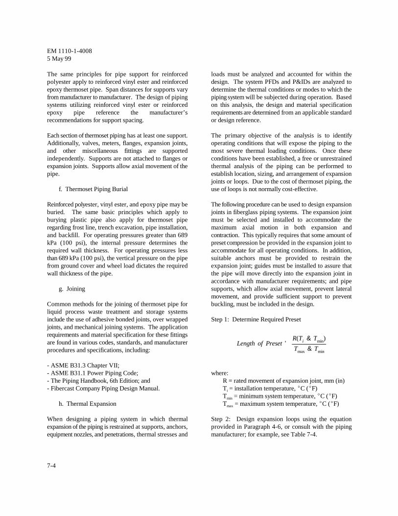
Length of Preset 'R(Ti & Tmin)
Tmax & Tmin
EM 1110-1-40085 May 99
7-4
The same principles for pipe support for reinforced loads must be analyzed and accounted for within thepolyester apply to reinforced vinyl ester and reinforced design. The system PFDs and P&IDs are analyzed toepoxy thermoset pipe. Span distances for supports vary determine the thermal conditions or modes to which thefrom manufacturer to manufacturer. The design of piping piping system will be subjected during operation. Basedsystems utilizing reinforced vinyl ester or reinforced on this analysis, the design and material specificationepoxy pipe reference the manufacturer’s requirements are determined from an applicable standardrecommendations for support spacing. or design reference.
Each section of thermoset piping has at least one support. The primary objective of the analysis is to identifyAdditionally, valves, meters, flanges, expansion joints, operating conditions that will expose the piping to theand other miscellaneous fittings are supported most severe thermal loading conditions. Once theseindependently. Supports are not attached to flanges or conditions have been established, a free or unrestrainedexpansion joints. Supports allow axial movement of the thermal analysis of the piping can be performed topipe. establish location, sizing, and arrangement of expansion
f. Thermoset Piping Burial use of loops is not normally cost-effective.
Reinforced polyester, vinyl ester, and epoxy pipe may be The following procedure can be used to design expansionburied. The same basic principles which apply to joints in fiberglass piping systems. The expansion jointburying plastic pipe also apply for thermoset pipe must be selected and installed to accommodate theregarding frost line, trench excavation, pipe installation, maximum axial motion in both expansion andand backfill. For operating pressures greater than 689 contraction. This typically requires that some amount ofkPa (100 psi), the internal pressure determines the preset compression be provided in the expansion joint torequired wall thickness. For operating pressures less accommodate for all operating conditions. In addition,than 689 kPa (100 psi), the vertical pressure on the pipe suitable anchors must be provided to restrain thefrom ground cover and wheel load dictates the required expansion joint; guides must be installed to assure thatwall thickness of the pipe. the pipe will move directly into the expansion joint in
g. Joining supports, which allow axial movement, prevent lateral
Common methods for the joining of thermoset pipe for buckling, must be included in the design.liquid process waste treatment and storage systemsinclude the use of adhesive bonded joints, over wrapped Step 1: Determine Required Presetjoints, and mechanical joining systems. The applicationrequirements and material specification for these fittingsare found in various codes, standards, and manufacturerprocedures and specifications, including:
- ASME B31.3 Chapter VII;- ASME B31.1 Power Piping Code; where:- The Piping Handbook, 6th Edition; and R = rated movement of expansion joint, mm (in)- Fibercast Company Piping Design Manual. T = installation temperature, EC (EF)
h. Thermal Expansion T = maximum system temperature, EC (EF)
When designing a piping system in which thermal Step 2: Design expansion loops using the equationexpansion of the piping is restrained at supports, anchors, provided in Paragraph 4-6, or consult with the pipingequipment nozzles, and penetrations, thermal stresses and manufacturer; for example, see Table 7-4.
joints or loops. Due to the cost of thermoset piping, the
accordance with manufacturer requirements; and pipe
movement, and provide sufficient support to prevent
i
T = minimum system temperature, EC (EF)min
max
EM 1110-1-40085 May 99
7-5
Table 7-4Loop Leg Sizing Chart for Fibercast RB-2530 Pipe
Do
mm (in)
Thermal Expansion, mm (in), versus Minimum Leg Length, m (ft)
25.4 mm 50.8 mm 76.2 mm 127 mm 178 mm 229 mm(1 in) (2 in) (3 in) (5 in) (7 in) (9 in)
33.40 (1.315) 1.22 m (4 ft) 1.52 m (5 ft) 1.83 m (6 ft) 2.44 m (8 ft) 2.74 m (9 ft) 3.05 m (10 ft)
48.26 (1.900) 1.83 m (6 ft) 2.44 m (8 ft) 2.74 m (9 ft) 3.66 m (12 ft) 4.27 m (14 ft) 4.88 m (16 ft)
60.33 (2.375) 2.13 m (7 ft) 3.05 m (10 ft) 3.66 m (12 ft) 4.88 m (16 ft) 5.79 m (19 ft) 6.40 m (21 ft)
88.90 (3.500) 2.74 m (9 ft) 3.96 m (13 ft) 4.88 m (16 ft) 6.10 m (20 ft) 7.32 m (24 ft) 8.23 m (27 ft)
114.3 (4.500) 3.66 m (12 ft) 4.88 m (16 ft) 6.10 m (20 ft) 7.62 m (25 ft) 9.14 m (30 ft) 10.4 m (34 ft)
168.3 (6.625) 4.57 m (15 ft) 6.40 m (21 ft) 7.62 m (25 ft) 9.75 m (32 ft) 11.6 m (38 ft) 13.1 m (43 ft)
219.1 (8.625) 5.18 m (17 ft) 7.01 m (23 ft) 8.84 m (29 ft) 11.3 m (37 ft) 13.1 m (43 ft) 14.9 m (49 ft)
273.1 (10.75) 5.79 m (19 ft) 7.92 m (26 ft) 9.75 m (32 ft) 12.5 m (41 ft) 14.6 m (48 ft) 16.8 m (55 ft)
323.9 (12.75) 6.10 m (20 ft) 8.53 m (28 ft) 10.4 m (34 ft) 13.4 m (44 ft) 15.8 m (52 ft) 18.0 m (59 ft)
355.6 (14.00) 5.79 m (19 ft) 7.92 m (26 ft) 9.75 m (32 ft) 12.5 m (41 ft) 14.9 m (49 ft) 16.8 m (55 ft)
Notes: D = outside diameter of standard Fibercast pipe. D may be different for other manufacturers.o o
Thermal expansion characteristics and required loop lengths will vary between manufacturers.Source: Fibercast, Piping Design Manual, FC-680, p. 6.
Although epoxies cure without the need for additional Reinforced polyester thermoset piping systems are theheat, almost all pipe is manufactured with heat-cure. most widely used due to affordability and versatility. TheReinforced epoxy piping systems are not manufactured to maximum continuous operating temperature for optimumdimensional or pressure standards. Therefore, chemical resistance is 71EC (160EF). Like the epoxies,considerable variation between manufacturers exist in reinforced polyester piping systems are not manufacturedregard to available size, maximum pressure rating and to dimensional or pressure standards. Variation ofmaximum temperature rating. Performance available piping sizes, maximum pressure rating, andrequirements, including manufacturing, conforms to maximum temperature ratings exist betweenASTM standards in order to not sole-source the piping manufacturers. Performance requirements, includingsystem. manufacturing, conform to ASTM standards in order to
not sole-source the piping system.
Schweitzer, Corrosion-Resistant Piping Systems, p. 102.1
The vinyl ester generally used for chemical process The advantage of furan resins is their resistance topiping systems is bisphenol-A fumarate due to good solvents in combination with acids or bases . Furans arecorrosion resistance . Reinforced vinyl ester piping difficult to work with and should not be used for1
systems vary by manufacturer for allowable pressures and oxidizing applications. Maximum operatingtemperatures. Performance requirements, including temperatures for furan resins can be 189EC (300EF).manufacturing, conforms to ASTM standards in order to Furan resin piping is commercially available in sizesnot sole-source the piping system. ranging from 15 to 300 mm (½ to 12 in) standard.
2
Schweitzer, Corrosion-Resistant Piping Systems, p. 96.2