Course Setting Bomb Sight Mk. IX 1 Course Setting Bomb Sight Mk. IX Leading Particulars Overall height with height bar folded 8 ½ in. Overall height with height bar erected 16 in. Overall length with zero enemy speed 22 ¼ in. Overall width 7 in. Weight of bomb sight excluding levelling bracket 14 lb. Weight of levelling bracket 2 ¼ lb. Size of storage case 23¾ x 11¾ x 8 5/8 in. Weight of storage case complete with bomb sight and levelling bracket 34 ¼ lb. Range of scales Mk. IXA Mk IXC Air speed 100 to 240 m.p.h. 87 to 208 knots Wind speed 0 to 70 m.p.h. 0 to 60 knots Ground speed 50 to 300 m.p.h. 50 to 260 knots Enemy speed 0 to 50 knots 0 to 50 knots Height 3,000 to 20,000 ft. 3,000 to 20,000 ft.
Transcript
Course Setting Bomb Sight Mk. IX 1
Course Setting Bomb Sight Mk. IX Leading Particulars Overall height with height bar folded 8 ½ in. Overall height with height bar erected 16 in. Overall length with zero enemy speed 22 ¼ in. Overall width 7 in. Weight of bomb sight excluding levelling bracket 14 lb. Weight of levelling bracket 2 ¼ lb. Size of storage case 23¾ x 11¾ x 8 5/8 in. Weight of storage case complete with bomb sight and levelling bracket 34 ¼ lb. Range of scales Mk. IXA Mk IXC Air speed 100 to 240 m.p.h. 87 to 208 knots Wind speed 0 to 70 m.p.h. 0 to 60 knots Ground speed 50 to 300 m.p.h. 50 to 260 knots Enemy speed 0 to 50 knots 0 to 50 knots Height 3,000 to 20,000 ft. 3,000 to 20,000 ft.
Course Setting Bomb Sight Mk. IX 2
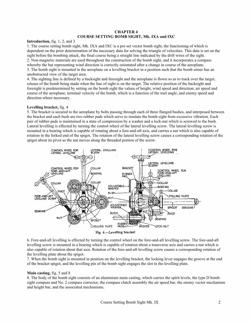
CHAPTER 4 COURSE SETTING BOMB SIGHT, Mk. IXA and IXC
Introduction, fig. 1, 2, and 3 1. The course setting bomb sight, Mk. IXA and IXC is a pre-set vector bomb sight, the functioning of which is dependent on the prior determination of the necessary data for solving the triangle of velocities. This data is set on the sight before the bombing attack, the final course being a straight line indicated by the drift wires of the sight. 2. Non-magnetic materials are used throughout the construction of the bomb sight, and it incorporates a compass whereby the bar representing wind direction is correctly orientated after a change in course of the aeroplane. 3. The bomb sight is mounted in the aeroplane on a levelling bracket in a position such that the bomb aimer has an unobstructed view of the target area. 4. The sighting line is defined by a backsight and foresight and the aeroplane is flown so as to track over the target, release of the bomb being made when the line of sight is on the target. The relative position of the backsight and foresight is predetermined by setting on the bomb sight the values of height, wind speed and direction, air speed and course of the aeroplane, terminal velocity of the bomb, which is a function of the trail angle, and enemy speed and direction where necessary. Levelling bracket, fig. 4 5. The bracket is secured to the aeroplane by bolts passing through each of three flanged bushes, and interposed between the bracket and each bush are two rubber pads which serve to insulate the bomb sight from excessive vibration. Each pair of rubber pads is maintained in a state of compression by a washer and a lock-nut which is screwed to the bush. Lateral levelling is effected by turning the control wheel of the lateral levelling screw. The lateral levelling screw is mounted in a bearing which is capable of rotating about a fore-and-aft axis, and carries a nut which is also capable of rotation in the forked end of the spigot. The rotation of the lateral levelling screw causes a corresponding rotation of the spigot about its pivot as the nut moves along the threaded portion of the screw.
6. Fore-and-aft levelling is effected by turning the control wheel on the fore-and-aft levelling screw. The fore-and-aft levelling screw is mounted in a bearing which is capable of rotation about a transverse axis and carries a nut which is also capable of rotation about that axis. Rotation of the fore-and-aft levelling screw causes a corresponding rotation of the levelling plate about the spigot. 7. When the bomb sight is mounted in position on the levelling bracket, the locking lever engages the groove at the end of the bracket spigot, and the levelling pin of the bomb sight engages the slot in the levelling plate. Main casting, fig. 5 and 8 8. The body of the bomb sight consists of an aluminium main casting, which carries the spirit levels, the type D bomb sight compass and No. 2 compass corrector, the compass clutch assembly the air speed bar, the enemy vector mechanism and height bar, and the associated mechanisms.
Course Setting Bomb Sight Mk. IX 3
9. The main casting has a transverse bush extending from the port side of the bomb sight into which the spigot of the levelling bracket enters when the sight is mounted in the aeroplane. The bomb sight is locked in position on the spigot of the levelling bracket by the spring-loaded locking lever engaging the spigot groove. By pulling the locking lever knob in a rearward direction the locking lever may be disengaged from the spigot to enable the sight to be removed from the levelling bracket. 10. Forward of the mouth of the transverse bush and screwed to the port side of the bomb sight is the levelling pin which locates in the slot milled in the levelling plate, thereby preventing the spigot from rotating in the transverse bush. 11. To the rear of the mouth of the transverse bush is the safety ring to which the safety catch of the leather lanyard is attached.
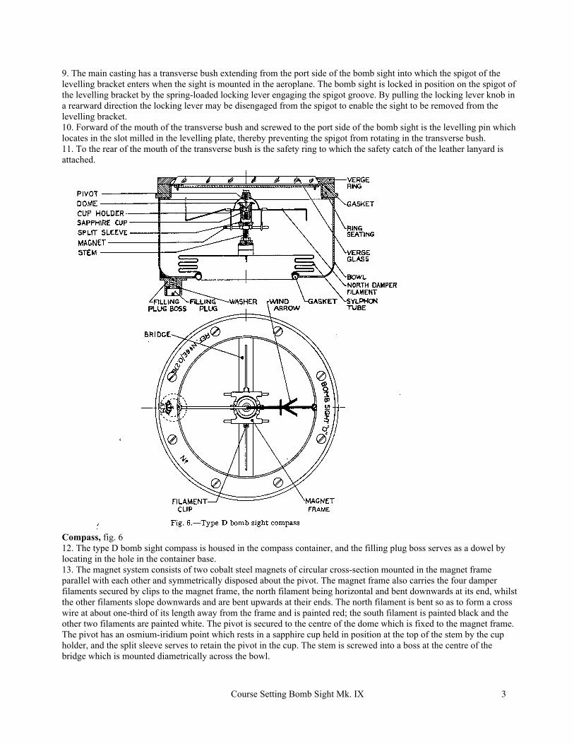
Compass, fig. 6 12. The type D bomb sight compass is housed in the compass container, and the filling plug boss serves as a dowel by locating in the hole in the container base. 13. The magnet system consists of two cobalt steel magnets of circular cross-section mounted in the magnet frame parallel with each other and symmetrically disposed about the pivot. The magnet frame also carries the four damper filaments secured by clips to the magnet frame, the north filament being horizontal and bent downwards at its end, whilst the other filaments slope downwards and are bent upwards at their ends. The north filament is bent so as to form a cross wire at about one-third of its length away from the frame and is painted red; the south filament is painted black and the other two filaments are painted white. The pivot is secured to the centre of the dome which is fixed to the magnet frame. The pivot has an osmium-iridium point which rests in a sapphire cup held in position at the top of the stem by the cup holder, and the split sleeve serves to retain the pivot in the cup. The stem is screwed into a boss at the centre of the bridge which is mounted diametrically across the bowl.
Course Setting Bomb Sight Mk. IX 4
14. The bowl is filled with alcohol diluted with distilled water, the solution having a gravity not exceeding 0.8l7 at 15 deg. C. Expansion is allowed for over a temperature range of - 50 deg. C. to + 50 deg. C. by a sylphon tube, which acts as a flexible metallic bellows, in the bottom of the bowl. The filling plug boss at the bottom of the bowl is closed by a threaded filling plug and washer and before sealing the compass is de-aerated in an exhaustion chamber 15. The verge glass is held in position by the verge ring, which is secured by screws to the seating, the joint being sealed by a rubber gasket. The wind arrow is mounted diametrically across the bowl underneath the verge glass and points along a line passing vertically above the centre of the filling plug. Half the arrow is painted black and carries the arrow head and the remaining half is painted white. Compass corrector, fig. 7 16. Correction of the compass is effected by the No. 2 corrector which is attached to the bottom of the bomb sight vertically below the compass.
Course Setting Bomb Sight Mk. IX 5
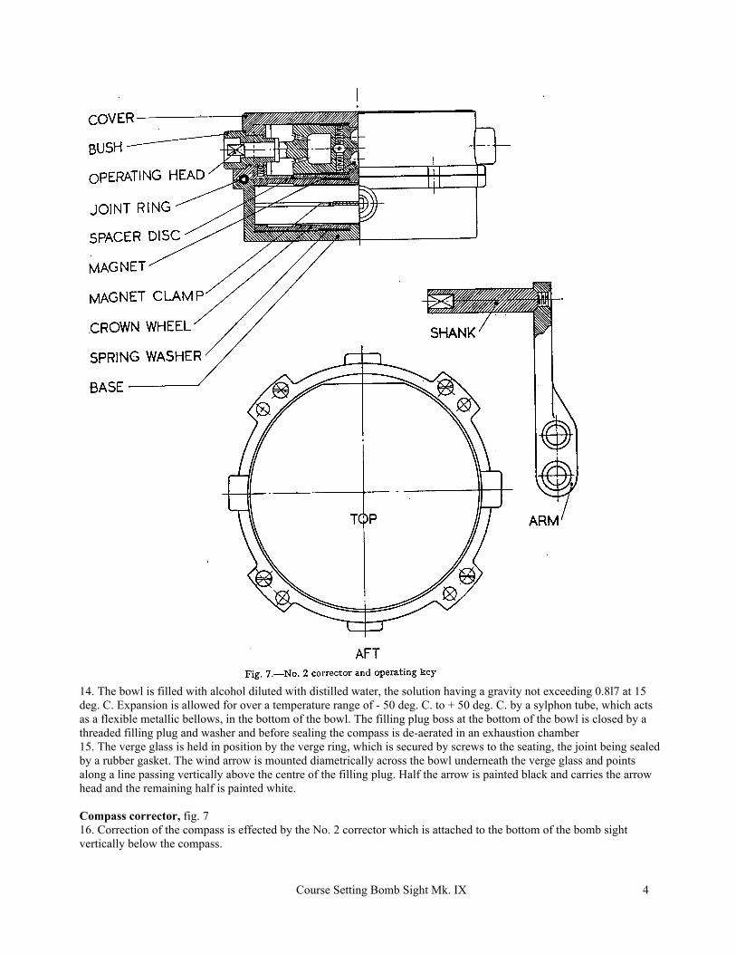
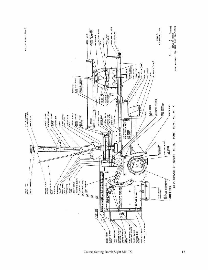
17. It consists of two pairs of magnets, one pair in the base and the other in the cover, attached to two pairs of crown wheels which engage bevel gears at the inner extremities of operating heads. The magnets are thus coupled in pairs and their positions relatively to the compass can be varied by rotation of the operating heads. The ends of the operating heads are square-shaped to engage a similarly shaped recess in the shank of the operating key. 18. The cover is secured to the base by four screws and the joint is sealed by a tubular rubber joint ring which fits into correspondingly shaped recesses in the base and cover. 19. Adjustment of the corrector is effected by rotation of the operating heads by the key. The position at which the magnets are parallel is not marked, but must be found by turning the operating heads to the extreme positions and determining the mid position. Spirit levels, fig. 8 20. The spirit levels consist of two aluminium alloy castings in each of which a graduated glass bubble tube is cemented with plaster of Paris. The fore-and-aft level is mounted on an angle bracket riveted to the port side of the bomb sight and the transverse level is mounted on the main casting underneath the drift scale, in which a slot is cut to enable the levels to be viewed from above. Compass clutch, fig. 5 21. The compass clutch is a mechanism mounted to the rear of the compass for rotating the compass with or without rotation of the compass dial. 22. The clutch comprises a shaft mounted vertically in the clutch casing, the middle portion of the shaft being of square cross-section and the end portions of circular cross-section. The upper portion of the shaft passes through a bush screwed into the clutch casing and terminates in a milled head. The clutch plunger is free to slide on the square portion of the shaft and is spring-loaded so as to apply pressure to clutch plates which are of celluloid and bronze arranged alternately. The lower circular portion of the shaft carries a clutch gear wheel which is free to turn, and a fixed gear wheel which is pinned to the shaft. A friction disk, having a leather washer riveted to its upper surface and prevented from rotating by two friction disk screws, is pressed with its leather washer against the underside of the fixed gear wheel by a coiled friction disk spring. 23. The compass clutch actuating stud is mounted in a bush in the clutch casing at right angles to the clutch shaft and carries a locking lever outside the casing, and an eccentrically mounted roller inside the casing. The locking lever is rotatable through 180 deg. and when set to the UNLOCKED position the eccentrically mounted roller raises the clutch plunger, thereby releasing the pressure on the clutch plates. With the locking lever in this position the compass and its container only are caused to rotate when the milled head is turned, and the bearing plate is free to rotate independently. 24. When the locking lever is set to the LOCKED position, turning of the milled head causes rotation of the compass and its container together with the bearing plate and retaining sleeve, i.e., the bearing plate and the compass are virtually locked together. Air speed drum, fig. 8 25. The air speed drum is on the starboard side of the instrument, and serves to adjust the length of the air speed bar over a true air speed range of 100 to 240 m.p.h. for the Mk. IXA, or 87 to 208 knots for the Mk. IXC. The air speed values are engraved on the drum and the index opposite which the air speed must be set is engraved on the locking ring. 26. The air speed drum assembly is mounted on a cover plate which is dowel pinned to the main casting of the bomb sight. An air speed drum pinion is mounted on the inside of the cover plate and axially with the air speed drum and its spindle passes through and is pinned to the drum. A locking ring is secured to the cover plate and serves as a clutch, the conical surfaces of the drum and the locking ring being held in contact by a coil spring. 27. The clutch serves to maintain the setting of the air speed drum and bar against vibration, and it is thus necessary to push the operating knob of the air speed drum inwards during adjustment of the setting. When the operating knob is released the two conical surfaces are pressed into contact and the friction thereby provided maintains the air speed setting.
Course Setting Bomb Sight Mk. IX 6
Course Setting Bomb Sight Mk. IX 7
Air speed spindle, fig. 9 28. The air speed spindle is mounted transversely in the instrument and carries an air speed shaft pinion, cam, and air speed pinion. 29. The air speed shaft pinion engages the air speed drum pinion and the air speed pinion engages the rack of the air speed bar; thus rotation of the air speed drum will cause an alteration in the effective length of the air speed bar. 30. The cam actuates a cam link and a trail plunger so that as the air speed setting is increased, the surface of the cam link upon which the lower roller of the trail plunger rolls is inclined more steeply. The effect of this is that for a given terminal velocity, the trail angle, i.e., the inclination of the height bar from the vertical, increases when the air speed is increased. Air speed bar, fig. 5 and 8 31. The air speed bar assembly extends longitudinally from the forward spout formed on the main casting, and its effective length is controlled by the air speed drum. 32. The air speed bar consists of a stem through which the main long shaft passes, its forward end terminating in a gear box housing the wind direction bevel gear wheels. The stem slides in a spherical bearing held in position at the forward end of the main casting by a threaded retaining ring, and the rack, which is secured by screws to the underside of the stem, engages the air speed pinion. The end of the stem within the main casting carries a guide fork set in a transverse position, the forked end of which slides on a guide rail which is mounted parallel with the air speed bar on the inner port side wall of the main casting. The guide fork is secured by a set-screw to the air speed bar stem, thereby preventing its rotation. Main long shaft, fig. 5 33. The main long shaft is splined for about one-third its length to receive the splined bevel gear wheel, whilst the remaining length passes through the air speed bar stem and is tapered. At the extremity of the tapered portion the shaft is turned cylindrical to receive the wind direction bevel gear wheel. Compass bevel gear wheels, fig. 5 34. The splined bevel gear wheel is mounted in a gimbal bearing, and has a shoulder formed on it which abuts the forward face of a bearing whilst a collar mounted on the gear wheel at the rear of the bearing is secured by a set-screw and maintains the gear wheel in position. The gimbal bearing is mounted in a bracket secured to the main casting. 35. The compass bevel gear wheel is mounted on a flanged shaft the end of which is milled square to receive the gear wheel, which is secured on the shaft by a ft/hd. screw. Rotation of the compass causes rotation of the compass bevel gear wheel which drives the splined bevel gear wheel. Wind direction bevel gear wheels, fig. 5 36. The wind direction bevel gear wheels are enclosed in a gear box mounted at the forward end of the air speed bar. The gear box has an end cover by which access to the bevel gears is attained. 37. The driving bevel gear is secured on the main long shaft and the driven gear is secured to the wind bar spindle. The bevel gearing is arranged so that the wind bar is always parallel with a line joining the centre of the compass filling plug to the centre of the compass container base, i.e., the wind arrow. Wind bar, fig. 5 and 8 38. The wind bar is of square section and has a longitudinal slot cut in its upper surface. On the lower face is formed a vertical spindle which passes into the gear box and carries the wind direction bevel gear wheel. 39. A block is fitted in each end of the bar and serves as a bearing for the wind screw, which is co-axial with the wind bar. The wind screw is secured at its tail by a collar and at its head by the wind screw knob. The end block at the head of the wind bar carries a small spring-loaded plunger which locates in one of ten spherical indentations at the back of the wind screw knob. The wind screw knob is knurled and has ten small flats upon which are engraved the figures 0-9 so disposed that the spring-loaded plunger engages a spherical indentation in the knob when its corresponding figure is vertically above the centre of the wind screw. This construction provides mechanical assistance in the accurate setting of the wind speed and holds the wind screw against subsequent vibration. 40. The wind bar is graduated from 0 to 70 m.p.h. for the Mk. IXA or from 0 to 60 knots for the Mk. IXC. The wind screw carries a nut in the form of a slider, the upper flat surface of which is flush with the wind speed scale and has an index line engraved on it. The end of the slider remote from the index line has a vertical spindle formed on it which passes through the ball pivot of a ground speed slider.
Course Setting Bomb Sight Mk. IX 8
Drift bar, fig. 5 and 8 41. The drift bar consists of an upper and lower drift bar held apart by distance and packing pieces and carrying the ground speed slider. The rear end of the drift bar is held in position on a drift bar pivot by a pivot screw. The forward end of the drift bar carries the drift wire extension mounted vertically. 42. On each side of the drift bar is mounted a pair of drift wires (one outer and one inner) extending the length of the bar and painted grey and white in alternate lengths. The forward ends of the drift wires terminate in end buttons which locate respectively in outer or inner plates which are separated by a packing piece, whilst the rear ends terminate in end collars and carry adjusting screws which abut the end collars and screw into a rear drift wire support. At about one-third the length of the drift bar from the forward end is a middle drift wire support, attached to the underneath surface of which are inner and outer drift wire clips which retain the drift wires in semi-cylindrical recesses in the under surface of the support. The drift wires each carry three orange, coloured timing beads 4.26 in. apart. 43. The upper drift bar is calibrated to read the ground speed on the port scale, the engraving of which is coloured white, and the time in minutes to travel 60 miles on the starboard scale, the engraving of which is coloured orange. Ground speed slider, fig. 5 and 8 44. A ground speed slider (lower) is of channel section, the vertical arms of which are extended forwards and carry two foresight points of conical shape and painted white. At the centre of the base, the channel section extends upwards to carry the ground speed slider (upper) on which are engraved the two indexes for the drift bar scales. 45. The ground speed slider is drilled, and carries a ball pivot through which the vertical spindle of the wind slider passes, and the collar pinned on the upper end of the spindle secures the ground speed slider. Auxiliary drift bar, fig. 10 46. The auxiliary drift bar consists of a frame at the ends of which are mounted drift wire supports which carry an auxiliary drift wire. The wire is painted black and grey in alternate lengths and is secured in position by small lock-nuts. 47. The frame is mounted on a quadrant, and two rollers carried by the quadrant fit in a curved slot in the frame, thus enabling the frame virtually to pivot about the apex of an indicator. 48. On both sides of the quadrant a scale graduated from minus 20 deg. to plus 20 deg. is riveted, and the index arm attached to the frame gives the drift angle on the scales. 49. The quadrant is hinged in the frame so that it may be folded over to port or to starboard and the frame is mounted on the forward part of the drift bar. A spring-loaded plunger incorporated in the quadrant locates in one of three holes on the bracket near the rear hinge, thereby holding the quadrant against vibration when folded to port or starboard or when raised to its vertical position. Enemy vector mechanism, fig. 5 and 9 50. The enemy vector mechanism consists essentially of an upper ring assembly and a lower ring assembly, the lower ring assembly being fixed to a ring mounting whilst the upper ring is mounted on trunnion bearings which allow it to pivot about a transverse axis and carries an enemy speed screw and upper slider to which is attached the height bar. 51. The lower ring assembly comprises an inner ring and inner ring gear secured together and free to rotate in the ring mounting, the bearing consisting of 32 rollers separated by distance pieces. The inner ring carries two parallel lower bars upon which slides the lower slider carrying the drift bar pivot, alignment plate, and drift bar. Mounted above the lower slider is a gimbal fork which is secured by a screw passing into the drift bar pivot, and the drift bar is secured to the pivot by a similar screw. The forward portion of the lower ring gear is protected by a cover screwed to the ring mounting. 52. The inner ring gear engages a pinion mounted on the ring mounting, and a bevel gear wheel mounted on the vertical spindle of the ring gear engages a bevel gear wheel mounted on the horizontal shaft upon which the enemy direction knob is secured. Thus rotation of the enemy direction knob causes rotation of the inner ring. 53. The upper ring assembly comprises an upper ring which is free to rotate within a ring bearing and is maintained in position by a retaining ring which is engraved from 0 to 360 deg. by 5 deg. graduations. The bearing consists of 32 rollers separated by distance pieces. 54. The two trunnions formed on the ring bearing are carried in the ring pivot blocks which are secured to the ring mounting, thus permitting the upper ring to rotate about a transverse axis by an amount known as the trail angle. An alteration in the trail angle may be caused by:-
(i) A reduction in terminal velocity setting, which rotates the trail plunger about its pivot in a counter-clockwise direction (looking at the starboard side), thereby causing the trail plunger roller to raise the upper ring quadrant. (ii) An increase in the air speed setting which causes the trail plunger to rise relatively to its bush, thereby causing the trail plunger roller to raise the upper ring quadrant.
Course Setting Bomb Sight Mk. IX 9
Course Setting Bomb Sight Mk. IX 10
Course Setting Bomb Sight Mk. IX 11
55. The trail plunger roller and upper ring quadrant are maintained in contact by the trail spring extending from the hook attached to the ring bearing to the hook attached to the main casting near the transverse bush. 56. The upper ring assembly carries two parallel enemy direction arrows, see fig. 8, so orientated as to point directly forward when an index engraved on the upper ring is aligned with a zero graduation on the retaining ring. 57. An enemy speed screw and enemy speed bar are also mounted on the upper ring assembly parallel with the enemy direction arrows, and carry the upper slider. The enemy speed bar is engraved from 0 to 50 knots by 10 knot graduations. The enemy speed screw is secured at its tail by a collar and at its head by a collar and an enemy speed knob. The bearing at the head of the enemy speed screw carries a small spring-loaded plunger, the function of which is similar to that of the plunger of the wind speed knob described in para. 39. The height bar base passes through a hole bored in the upper slider and is secured to the gimbal by a pin. 58. When the enemy speed is set to zero, rotation of the enemy direction knob rotates the lower inner ring and ring gear together with the lower slider and bars, and also the upper ring, enemy direction arrows, upper slider, enemy speed screw, and bar. The two ring assemblies are inter-connected, so as to rotate together, by a locating tongue screwed to the lower inner ring and bearing against two vertical slides machined in the upper ring. The height bar and gimbal do not rotate except when the drift angle is altered; and when the enemy speed is set to zero the axis of the height bar passes through the centre of the upper ring. The effect of making an enemy speed setting is to move the base of the height bar to an eccentric position relatively to the upper ring. Height bar, fig. 5 and 10 59. The height bar is of rectangular section and capable of pivoting about a wind gauge bar bolt from the vertical forward to the horizontal position for storage purposes. A height bar screw extends the length of the height bar, the upper and the lower ends bearing in upper and lower bushes respectively. The upper end of the height bar screw terminates in a height bar knob the rotation of which causes a height slider nut to move up or down the screw. 60. The forward face of the height bar has a slot running the length of the bar, in which slides a projection of the nut to which is screwed the height slider. The height slider has two conical backsight points which are carried each in a ring-shaped mounting set one on the port and one on the starboard side of the height bar and inclined at an angle of 60 deg. to the vertical. 61. The height bar is held rigidly in its vertical position by the eccentric action of a clamp which is attached to the lower end of the height bar by a link. When in the operative position the clamp locates in the cylindrical groove in the height bar base. 62. The starboard side face of the height bar has an inset timing height scale graduated from 600 to 1,450 ft. in 100 ft. divisions coloured orange, and the index for this scale is on the height slider and has an arrow also coloured orange engraved upon it. 63. The rear face of the height bar is designed to receive a detachable height scale. The lower end of the height scale locates in a vertical slot in the height bar forward of the clamp and the upper end is held in position by a height scale catch. 64. The height scale catch is slidably mounted on the upper bush of the height bar and is spring-loaded so as to hold the height scale in position. Two small leaf springs (not shown) are secured in recesses in the upper part of the height bar behind the height scale to facilitate the removal of the height scale when the catch is raised. Two small index lines are engraved on the rear bevelled faces of the height slider and may be adjusted to the desired value on the height scale by rotating the height bar knob. Wind gauge bar, fig. 10 and 11 65. The wind gauge bar hinges about the same axis as the height bar, and when in the stowed position it lies close to the height bar, being retained in position by two spring-loaded plungers which locate in indentations in lugs formed on the inner sides of a hinge. 66. A series of curves, known as time curves, are engraved on the upper face of the wind gauge bar and a cursor slides along it. The cursor is engraved with a scale of TRUE AIR SPEED in m.p.h. for the Mk. IXA or knots for the Mk. IXC and has at its side a lug with a hole for insertion of a chinagraph pencil for marking the glass cover plate. The opposite side of the cursor carries a pressure pad and spring to prevent movement of the cursor as a result of vibration. 67. A set of calibrated wind gauge bars is supplied with each sight. Each wind gauge bar has a range of 30 m.p.h. for the Mk. IXA or 30 knots for the Mk. IXC and the bar most suitable for the normal bombing speed of the aeroplane is fitted to the bomb sight before flight.
Course Setting Bomb Sight Mk. IX 12
Course Setting Bomb Sight Mk. IX 13
Drift scale, fig. 5 and 8 68. The drift scale is attached by six screws to a drift scale bracket situated to the rear of the height bar. A scale of drift angle, with a range of plus 50 to minus 50, is engraved in degrees on an upper forward face, and a small scale with a range of ten deg. is engraved on an upper rear face. A slot, through which the lateral spirit level is viewed, is cut in the centre of the drift scale. Pencil holder and sharpener, fig. 8 69. The pencil holder and sharpener are situated on the port side of the sight. The pencil holder is of tubular shape with a longitudinal slot down one side to allow the holder to spring and thus grip the pencil. At the top and bottom of the holder, lugs are formed with holes through which screws pass for attachment to the sight. The pencil sharpener is a rectangular piece of duralumin, slightly bent longitudinally and sharpened at its outer edge: it is attached to the drift scale by two screws. Lanyard. 70. The lanyard, the purpose of which is to prevent loss of the sight should it come adrift, is made of stout leather, doubled and bound at each end to form loops. One of the loops is passed through the safety catch, a special spring-loaded catch for attachment to the safety ring on the side of the main casting.
INSTRUCTIONS FOR USE Introduction 71. The following instructions apply to the bomb aimer and indicate the procedure when using the bomb sight under normal operational conditions. Air crews will develop their own technique for applying these instructions and can summarize and modify them in the light of their own experience. Instructions for the use of the bomb sight under certain more specialized conditions of target, bomb load, and nature of attack, are included in Armament Training Notes issued from time to time by Command or Group Headquarters: air crews should, therefore, keep themselves informed of the contents of such notes and refer to them for additional guidance when necessary. Procedure before flight 72. Ensure that the maintenance operations stated in A.P.1730A, Vol. II, Part 3, Sect. 2, Chap. 4 have been done, and check that the bomb sight is correctly installed in the aeroplane. 73. Ensure that in addition to the instruments fixed in the aeroplane for the use of the bomb aimer the following equipment is also to hand:-
(i) Correction cards for the altimeter, air speed indicator, and bomb sight compass, (ii) Height and air speed computor, Mk. I for altimeters calibrated for the isothermal convention, or Mk. II for I.C.A.N. calibration. See A.P. 1275, Vol. I, Sect. X, Chap. l and 6 for description and use of these computors, (iii) Course and speed calculator, Mk. II or IIA, (iv) Height scale for each type of bomb carried,
Course Setting Bomb Sight Mk. IX 14
(v) If low level attacks are likely to be made, graphs for low level bombing, or summarized data abstracted from them. The graphs are on R.A.F. Forms 1225, l225A, 1226, and 1226A, (vi) Stop watch, (vii) Chinagraphp pencil.
74. Record upon a card the following information :- (i) The location, nature, and height of the target, and any aids to recognition. For moving targets, information as to probable course and speed, if available, (ii) The type of attack to be made, (iii) The disposition and nature of the bomb load, and terminal velocities of each type of bomb.
75 Make the following adjustments to the sight:- (i) Ensure that the compass clutch locking lever is in the LOCKED position, so that the bearing plate is locked to the compass. This operation will subsequently be referred to as “locking the bearing plate”‚ (ii) Set the enemy speed to zero and enemy direction to approximately 270 deg., (iii) Set the terminal velocity to infinity, (iv) Set the wind speed to zero, and rotate the compass clutch milled head to set the wind bar approximately at right angles to the air speed bar, (v) Set the air speed to the approximate operational speed, (vi) Fix the wind gauge bar having the most suitable range of air speeds.
76 Adjust the altimeter to read either zero or the height of the departure aerodrome above sea level, and set the barometric pressure and temperature on the height and air speed computor. Procedure on approaching the target area (finding wind speed and direction) General 77. The majority of errors which occur in the use of the sight arise from incorrect settings of wind speed and direction. It is emphasized that the wind speed and direction may change considerably during a flight, and that the meteorological forecast for the target area will rarely be found accurate. Whenever conditions allow, the wind speed and direction in the target area should be found by one of the following three methods. If, however, this is not possible, the wind speed and direction determined by the navigator on the flight to the target should be set on the sight, or, failing this, the settings should be made according to the meteorological forecast. Whichever method of setting wind speed and direction is employed, greatest bombing accuracy will be achieved by bombing up or down wind and using the method of stick bombing to cover range errors. 78. The course setting bomb sight, Mk. IXA or IXC can be used to find the wind speed and direction. The method chosen will depend on the time available, whether flying singly or in formation, and on the conditions encountered in the vicinity of the target. When the wind speed and direction have been found they can be left set on the sight for the bombing run. 79. The first two methods described necessitate knowing the air speed and measuring the drift on two or more courses. The third method necessitates knowing the air speed and observing the drift and ground speed on one course 80. The pilot should be instructed to fly on a level course at intended bombing height and air speed. The readings of the altimeter and air speed indicator should be checked with the pilot’s instruments, corrected by reference to the correction cards, then transferred to the height and air speed computor. The true air speed and true height (either above the home aerodrome or sea level) can now be read off when required. The air speed drum should be rotated to set this true air speed on the air speed bar, and the height bar clamped into the vertical position. Use of auxiliary drift bar 81. Drift can be most accurately and conveniently observed by using the auxiliary drift bar which has all the advantages of a backward reading drift sight, in that the ground object selected for observation need not be one that will pass directly under the aeroplane, so that the process of trial and error associated with the forward reading main drift wires is eliminated. Thus, whenever practicable, the auxiliary drift bar should be employed. 82. The auxiliary drift bar should be folded down on the side which is least obstructed visually; the main drift wires should be set to zero drift (the drift angle set on the drift wires can be read at the point where the wind gauge bar crosses the main drift scale), and the backsight set to some convenient position for comfortable sighting. A suitable ground object which, when seen from the backsight, appears on the auxiliary drift bar at the point shown by the indicator should be observed and the auxiliary drift bar rotated by hand to keep the object on the wire. 83. The reading shown on the auxiliary drift scale is then the drift of the aeroplane and is read plus or minus, according to the engraving on the scale; this value can then be set on the main drift scale on the plus or minus side.
Course Setting Bomb Sight Mk. IX 15
84. If a suitable ground object cannot be found with the main drift wires set at zero drift, the main drift wires can be swung to port or starboard to facilitate the selection of a suitable ground object to observe on the auxiliary drift bar. If this is done, the correct drift angle will be the algebraic sum of the angles recorded on the main and auxiliary drift scales. Precautions to be observed 85. In observing drift, either on the main or auxiliary drift wires, it is of great importance to look through the backsight and to keep the head perfectly steady, resisting the tendency to keep the observed object on the drift wires by moving the head. 86. It should be remembered that during a course change, both the spirit levels and the compass filament become displaced from their equilibrium positions, so that time should be allowed for them to settle before reference is made to them. 87. When observing the compass filament or wind arrow before moving the bearing plate, it is important to look vertically downwards to avoid parallax errors. 90 deg. method 88. With the true air speed set on the air speed drum, the height bar in the vertical position, and the wind speed set to zero, inform the pilot of the intended method for finding the wind speed and direction and proceed as follows :-
(i) Instruct the pilot to fly up or down wind at bombing height, and at constant air speed and, when the course is steady, level the sight and check that ground objects appear to move parallel with the drift wires. If they do not, instruct the pilot to make minor course changes in the appropriate directions until they do, (ii) Rotate the wind arrow by means of the compass clutch milled head until the wind arrow is pointing directly forward for down-wind flight, or directly aft for up-wind flight. The approximate direction of the wind will be known by observation of the direction of drift before the required course was obtained, (iii) Unlock the bearing plate and rotate it to set “red on red”, i.e., the red marked north point on the bearing plate vertically over the red compass filament. Lock the bearing plate, (iv) Instruct the pilot to make a course change of approximately 90 deg. Endeavour to keep “red on red” throughout this operation by rotating the compass clutch milled head, finally checking when the compass needle has settled. (v) Rotate the wind speed knob until objects on the ground appear to move parallel with the drift wires. If this is impossible, it indicates that the wind arrow was set in the wrong direction in operation (iii) and it should be rotated through 180 deg. (vi) If required, the wind speed can be read off the scale on the wind speed bar, and the wind direction can be read on the bearing plate vertically over the black tail of the wind arrow.
Three course method 89. With the height bar in the vertical position and the true air speed set on the air speed drum, inform the pilot of the intended method for finding wind speed and direction. Turn the wind speed knob to give the maximum reading on the wind speed bar, and unlock the bearing plate. 90 First course.-Proceed as follows :-
(i) Instruct the pilot to fly on a straight level course at bombing height and at constant air speed. When the course is steady, level the sight, (ii) Use the auxiliary drift bar to find the drift angle see para. 82 to 84, then rotate the compass clutch milled head to set the main drift wires to the drift angle, (iii) Rotate the bearing plate to set “red on red”, (iv) Instruct the pilot to make a course change of approximately 60 deg., or, alternatively, 120 deg. During the turn, fold down the wind gauge bar on to the bearing plate, insert the chinagraph pencil through the hole in the wind gauge bar cursor and rule a line on the bearing plate by moving the cursor along the wind gauge bar. Fold back the wind gauge bar.
91. Second course.-When steady on the second course, repeat the procedure described in para. 90, except that when calling for the course change of 60 deg. or 120 deg. warn the pilot that this must not be in a direction that will bring the third course parallel with the first. 92. Third course.-When steady on the third course, repeat the procedure described in para. 90, but instead of asking for another course change, inform the pilot that he need no longer concentrate on course keeping, as the necessary data has been collected. The three lines ruled on the bearing plate should, theoretically, meet in a point if the drift has been correctly observed. In practice, these three lines usually form a small triangle or “cocked hat”; if any side of this triangle is greater in length than 3/8 in. it is an indication that the errors accumulated are excessive and the process should be repeated.
Course Setting Bomb Sight Mk. IX 16
93. Setting the wind speed and direction.-The wind speed and direction can be set on the sight as follows :-- (i) Rotate the bearing plate to bring the centre of the “cocked hat” above the tail of the wind arrow, then lock the bearing plate, (ii) Use the compass clutch milled head to rotate the wind arrow to bring it perpendicular to the fore-and-aft line of the sight, (iii) Fold the wind gauge bar down on to the bearing plate and adjust the wind speed knob and wind gauge bar cursor so that the hole in the cursor is over the centre of the “cocked hat”, (iv) If required, read off the wind speed on the scale on the wind speed bar and the wind direction on the bearing plate over the black tail of the wind arrow.
Timing bead and wind gauge bar method 94. With the height bar in its operational position and the air speed drum set to the true air speed, warn the pilot of the intended method of finding wind speed and direction, and proceed as follows :-
(i) Instruct the pilot to fly on a straight level course at bombing height and at constant air speed, and, when the course is steady, carefully level the sight, (ii) Set the wind speed knob so that the wind speed is at its maximum value, (iii) Set the true height above the ground on the red height scale, (iv) Use the auxiliary drift bar as explained in para. 82 to 84 to find the drift angle, and set this angle on the main drift scale by rotation of the compass clutch milled head, (v) Select a convenient object on the ground that appears to be moving down one drift wire, and, viewing it through the backsight, measure with a stop watch the time it takes to pass from one timing bead to the next, (vi) Repeat for two or three objects to obtain an average value for the time taken, (vii) Without altering the drift angle, lower the wind gauge bar on to the bearing plate, (viii) Unlock the bearing plate, rotate it to bring “red on red”, then lock the bearing plate, (ix) Slide the cursor along the wind gauge bar until the appropriate air speed graduation on the cursor cuts the time curve corresponding to the number of seconds obtained from operation (vi). Through the hole in the cursor, mark a point on the bearing plate with the chinagraph pencil, (x) Unlock and rotate the bearing plate so that this point is vertically over the tail of the wind arrow; lock the bearing plate, (xi) Rotate the compass clutch milled head to bring the wind arrow approximately perpendicular to the fore and aft line of the sight (xii) Adjust the wind speed knob and slide the cursor along the wind gauge bar until the hole in the cursor is over the point marked on the bearing plate, (xiii) If required, read off the wind speed on the wind speed bar and the wind direction on the bearing plate over the black tail of the wind arrow.
Procedure for bombing a stationary target 95. If the wind speed and direction have been found by any of the three methods described above, these settings will be already on the sight. Otherwise, set the wind speed on the wind bar by rotation of the wind speed knob, and, to set the wind direction, unlock the bearing plate, rotate it to bring the correct wind direction vertically over the black tail of the wind arrow, and re-lock the bearing plate. Finally bring “red on red” by rotating the compass clutch milled head. 96. Clip the appropriate height scale to the height bar, set the true air speed on the air speed drum, and the true height above the target on the white height scale. Set on the terminal velocity knob the terminal velocity of the bomb to be dropped. 97. Instruct the pilot to fly on a course which will, in his opinion, track the aeroplane over the target. When steady on this course, carefully level the bomb sight and bring “red on red” by rotating the compass bowl knob. If the wind speed and direction have been accurately determined, objects on the ground will appear to move parallel with the drift wires. Observe the apparent motion of the target, and if it appears to be moving to the left or to the right of the drift wires, assess the course change required and direct the pilot accordingly, (if the azimuth bracket and steering indicator are installed, see Chap. 6 for instructions for use.) 98. It is very important that the target should be viewed through the backsight, with the head kept steady, and that the sight be level before deciding whether a turn is necessary. During the turn endeavour to keep “red on red” by rotation of the compass clutch milled head: when the turn is complete and the compass needle has settled, check that “red is on red”. If time allows, and if further course corrections are required, repeat the above procedure, taking the same precautions. Do not call for a turn immediately before release point. Try to have at least 10 sec. of straight flight immediately prior to
Course Setting Bomb Sight Mk. IX 17
bomb release, even though the final course appears to be not quite correct. Concentrate now on sighting, and when the backsight, the foresight, and the target are aligned, release the bomb. Procedure for bombing at heights below 3,000 ft. 99. As the height scales supplied have a lower limit of 3,000 ft. a method of using the bomb sight at lower altitudes has been devised. In this method, the front red timing bead is used as a fixed foresight and the height of the backsight is determined by reference to graphs. 100. The following procedure should be adopted :-
(i) Set the terminal velocity to infinity, (ii) On approaching the target, note the indicated height and estimate the ground speed. Obtain the appropriate height setting from the graph, and set this on the red height scale, (iii) Release the bomb when the target, front timing bead, and the back sight are aligned.
101. The accuracy of this method may be improved by making a rough drift setting on the sight, and giving course corrections to the pilot, but, as the bombing run will usually be short, time may not be available. Procedure for bombing a moving target 102. The procedure is the same as for a stationary target, except that the enemy speed and direction are set on the sight. The enemy speed, known or estimated, is set on the enemy speedbar by rotation of the enemy speed knob. If the enemy direction is not known, rotate the enemy direction knob to bring the two arrows on the enemy vector ring parallel with the observed course of the enemy. 103. During course changes of the aeroplane, in addition to keeping “red on red”, rotate the enemy direction knob to keep these arrows parallel with, and pointing in the same direction as, the enemy course, finally checking when the aircraft course is steady. If all the settings on the sight are correct, the enemy will appear to move parallel with the drift wires and the bomb should be released when target, foresight, and backsight are aligned.