61
COVANTA FICHTNER 17/11/16 Rookery South ERF - Supporting Information Page i S2118-0320-0008JRS COVANTA ROOKERY SOUTH ERF SUPPORTING INFORMATION
COVANTA FICHTNER
17/11/16 Rookery South ERF - Supporting Information Page i
S2118-0320-0008JRS
COVANTA
ROOKERY SOUTH ERF
SUPPORTING INFORMATION

COVANTA FICHTNER
17/11/16 Rookery South ERF - Supporting Information Page ii
S2118-0320-0008JRS
COVANTA
ROOKERY SOUTH ERF
SUPPORTING INFORMATION
Document Production & Approval Record
ISSUE NO. 4 NAME SIGNATURE POSITION DATE
Prepared by: Eleanor Haynes
Environmental
Engineer
17/11/2016
Checked by: James Sturman
Associate Senior
Consultant
17/11/2016
Reviewed by: Stephen Othen
Technical Director 17/11/2016
Document Revision Record
ISSUE
NO.
DATE DETAILS OF REVISIONS PREPARED
BY
CHECKED
BY
1 9/9/2016 For Client. EH/JRS SMO
2 29/09/2016 Updated following Client comments EH SMO
3 11/11/2016 Updated following Client comments EH/JRS SMO
4 17/11/2016 Updated following Client comments JRS SMO
5
6
© 2016 Fichtner Consulting Engineers. All rights reserved.
This report and its accompanying documents contain information which is confidential and is
intended only for the use of Covanta. If you are not one of the intended recipients any disclosure,
copying, distribution or action taken in reliance on the contents of the information is strictly
prohibited.
Unless expressly agreed, any reproduction of material from this report must be requested and
authorised in writing from Fichtner Consulting Engineers. Authorised reproduction of material must
include all copyright and proprietary notices in the same form and manner as the original, and must
not be modified in any way. Acknowledgement of the source of the material must also be included
in all references.

COVANTA FICHTNER
17/11/16 Rookery South ERF - Supporting Information Page iii
S2118-0320-0008JRS
TABLE OF CONTENTS
TABLE OF CONTENTS ........................................................................................................... III
1 Introduction .............................................................................................................. 1
1.1 The applicant .................................................................................................... 1
1.1.1 Covanta .............................................................................................................. 1
1.1.2 Veolia ................................................................................................................. 1
1.2 The site ............................................................................................................ 2
1.3 Listed activities ................................................................................................. 2
1.4 The Installation ................................................................................................. 2
1.4.1 The waste incineration plant .................................................................................. 3
1.4.1.1 Raw materials ...................................................................................... 3
1.4.1.2 Combustion process .............................................................................. 4
1.4.1.3 Energy recovery ................................................................................... 5
1.4.1.4 Gas cleaning......................................................................................... 5
1.4.1.5 Emissions monitoring ............................................................................ 5
1.4.2 IBA .................................................................................................................... 6
1.4.2.1 Overview ............................................................................................. 6
1.4.2.2 Reception and drainage ......................................................................... 6
1.4.2.3 IBA processing ..................................................................................... 7
1.4.2.4 IBA Output ........................................................................................... 8
1.4.2.5 Flood risk ............................................................................................. 8
2 Other Information for Application Form ........................................................................ 9
2.1 Raw materials ................................................................................................... 9
2.1.1 Types and amounts of raw materials ...................................................................... 9
2.1.2 Raw materials selection ....................................................................................... 11
2.1.2.1 Acid gas abatement .............................................................................. 11
2.1.2.2 NOx abatement reagent ....................................................................... 12
2.1.2.3 Auxiliary fuel ....................................................................................... 12
2.2 Incoming waste management ............................................................................ 13
2.2.1 Waste to be burned ............................................................................................. 13
2.2.2 Waste handling ................................................................................................... 15
2.2.3 Waste minimisation (minimising the use of raw materials) ....................................... 15
2.2.3.1 Feedstock Homogeneity ........................................................................ 16
2.2.3.2 Dioxin & Furan Reformation .................................................................. 16
2.2.3.3 Furnace Conditions ............................................................................... 16
2.2.3.4 Flue Gas Treatment Control ................................................................... 16
2.2.3.5 Waste Charging ................................................................................... 17
2.3 Water use ........................................................................................................ 17
2.3.1 Surface water ..................................................................................................... 18
2.3.2 Process water ..................................................................................................... 18
2.3.2.1 Steam boiler........................................................................................ 18
2.3.2.2 Demineralisation plant .......................................................................... 19
2.3.2.3 Dirty Water Tank ................................................................................. 19
2.3.2.4 Ash Quench System ............................................................................. 19
2.3.2.5 IBA water use ...................................................................................... 19
2.3.2.6 Other uses .......................................................................................... 20
2.3.3 Site Drainage ..................................................................................................... 20
2.3.3.1 Spillage management ........................................................................... 20
COVANTA FICHTNER
17/11/16 Rookery South ERF - Supporting Information Page iv
S2118-0320-0008JRS
2.4 Emissions ........................................................................................................ 21
2.4.1 Emissions to air .................................................................................................. 21
2.4.2 Odour ................................................................................................................ 22
2.4.3 Emissions to water .............................................................................................. 22
2.4.4 Contaminated water ............................................................................................ 23
2.4.5 Fugitive Emissions from IBA Storage ..................................................................... 23
2.5 Emissions monitoring ........................................................................................ 23
2.5.1 Monitoring emissions to air .................................................................................. 23
2.5.1.1 Reliability ............................................................................................ 24
2.5.1.2 Start-up and shutdown ......................................................................... 25
2.5.2 Monitoring emissions to land ................................................................................ 25
2.5.3 Monitoring emissions to water .............................................................................. 25
2.5.4 Monitoring emissions from the IBA facility .............................................................. 25
2.5.5 Waste Incineration Plant Process Monitoring ........................................................... 25
2.6 Technology selection ......................................................................................... 27
2.6.1 Combustion technology ....................................................................................... 27
2.6.2 NOx Reduction System ........................................................................................ 28
2.6.2.1 Flue Gas Recirculation (FGR) ................................................................. 29
2.6.3 Acid gas abatement system ................................................................................. 30
2.6.4 Control of particulate matter ................................................................................ 31
2.6.5 Steam condenser ................................................................................................ 31
2.6.6 IBA facility ......................................................................................................... 32
2.8 Energy efficiency .............................................................................................. 38
2.8.1 Basic energy requirements ................................................................................... 38
2.8.1.1 Operating and maintenance procedures .................................................. 40
2.8.1.2 Energy efficiency benchmarks ............................................................... 41
2.8.2 Further energy efficiency requirements .................................................................. 41
2.9 Waste recovery and disposal .............................................................................. 41
2.9.1 Metals separated from the received waste ............................................................. 41
2.9.2 Incinerator bottom ash (IBA)................................................................................ 41
2.9.3 Air pollution control residues ................................................................................ 42
2.10 Management .................................................................................................... 43
2.10.1 Management systems .......................................................................................... 43
2.10.1.1 Scope and structure ............................................................................. 44
2.10.1.2 General Requirements .......................................................................... 44
2.10.1.3 Personnel ............................................................................................ 44
2.10.1.4 Competence, Training and Awareness .................................................... 44
2.10.1.5 Competence ........................................................................................ 45
2.10.1.6 Induction and Awareness ...................................................................... 45
2.10.1.7 Training .............................................................................................. 45
2.11 Closure ........................................................................................................... 45
2.12 General ........................................................................................................... 45
2.12.1 Site closure plan ................................................................................................. 45
2.12.1.1 General requirements ........................................................................... 46
2.12.1.2 Specific details ..................................................................................... 46
2.12.1.3 Disposal routes .................................................................................... 46
2.13 Improvement programme ................................................................................. 46
2.13.1 Pre-Commissioning ............................................................................................. 46
2.13.2 Post commissioning ............................................................................................. 47

COVANTA FICHTNER
17/11/16 Rookery South ERF - Supporting Information Page 1
S2118-0320-0008JRS
1 INTRODUCTION
Covanta Rookery South Limited (Covanta) is proposing to build an Energy Recovery Facility (ERF)
at Rookery Pit in Stewartby, Bedfordshire, referred to as the Rookery South ERF. The Installation
will be arranged in a three stream format with the capacity to process 585,000 tonnes of mixed
Municipal Solid Waste (MSW) and commercial, industrial and trade waste per annum. The facility
will be designed to export 52.5 MWe and up to 40 MWth of heat.
This document and its annexes contain the supporting information for Covanta’s application for an
Environmental Permit (EP). They should be read in conjunction with the formal application form.
Section 1 of this document provides an overview of the proposed Installation. Section 2 provides
further information in response to specific questions in the application form.
1.1 The applicant
Covanta and Veolia UK Limited (Veolia) have joined forces, under a Project Development
Agreement, to develop the Energy Recovery Facility at Rookery South Pit. The project team
are currently working together to discharge the planning conditions and secure the EP for the
operation of the facility. For the purposes of the EP application, and in accordance with the
definitions of the ‘legal operator’ as stated in ‘Guidance: Legal operator and competence
requirements: environmental permits’, Covanta Energy will be the Operator of the Facility
and therefore the applicant for the purposes of the EP.
1.1.1 Covanta
Covanta, the parent company of Covanta Rookery South Limited, is an internationally
recognised owner and operator of large-scale ERFs. The company delivers environmentally
responsible and increasingly innovative solutions for the public, local government, industry
and commerce, enabling its customers to reduce their impact on the environment. Covanta
processes approximately 20 million tons of municipal solid waste each year which
conserves over 25 million cubic yards of landfill space and generates 9 million megawatt
hours of electricity - enough clean, renewable energy to power for one million homes. All
of Covanta’s EfW projects feature state-of-the-art emission control technology.
Covanta believes that recovering energy from the waste that remains after recycling is an
important part of sustainable waste management and a key to reducing the hundreds of
millions of tons of waste sent to landfills each year. Energy-from-Waste (EfW) takes non-
hazardous waste destined for landfills, combusts it in specially designed boilers then
recovers the heat to generate steam to use in energy generation or other industrial
processes.
Covanta is proud of its environmental and safety performance having received a wide
range of awards from US government bodies. These include OSHA VVP star award and
various US State Environmental Awards.
Covanta is currently constructing the Dublin Energy from Waste facility in conformance
with the waste incineration requirements of the Industrial Emissions Directive (IED) and
understands how these requirements must be applied to the Rookery South Facility.
1.1.2 Veolia
The Veolia group is the global leader in optimized resource management. With over
174,000 employees worldwide, the Group designs and provides water, waste and energy
management solutions that contribute to the sustainable development of communities and
industries. Through its three complementary business activities, Veolia helps to develop
access to resources, preserve available resources, and to replenish them.

COVANTA FICHTNER
17/11/16 Rookery South ERF - Supporting Information Page 2
S2118-0320-0008JRS
1.2 The site
The application site (“the Site”) comprises 17 hectares of land located at Rookery Pit,
Stewartby, Bedfordshire (National Grid Reference 501290E 241040N), as illustrated in the
location plan presented in Annex 1. The Site is located within the district of Central
Bedfordshire Council and borders the Bedford Borough Council area of jurisdiction. The area
beyond the Site is predominantly rural in nature.
Rookery Pit is an area of approximately 200 hectares comprising two former clay pits (referred
to as Rookery North and Rookery South) associated with the former Stewartby Brickworks.
The Site will be located in the north-western quadrant of Rookery South pit.
The Site is bounded to the east and west by two railway lines. The A507 is approximately 2.9
km to the south, and the A421 is approximately 1.8 km to the north-west.
To the immediate south of the Site is a line of trees and South Pillinge Farm, located
approximately 250 m away. This is the closest residential receptor. To the immediate west of
the Site is the Marston Vale Millennium Country Park. Approximately 0.5 km to the north-
west is Stewartby Lake. Ampthill Park, a nationally important historic park, is located
approximately 2.5 km to the south-east of the Site.
To the north of the Site, and just beyond Green Lane, are the former brickworks buildings.
Approximately 1.1 km north is the settlement of Stewartby. Other neighbouring residential
areas include Houghton Conquest approximately 2.7 km to the east and Marston Moretaine
1.2 km to the west.
1.3 Listed activities
The principal activities undertaken at the Installation will consist of a combination of
Schedule 1 installation activities1 and directly associated activities, as presented in Table 1.1.
Table 1.1: Environmental Permit Activities
Type of Activity Schedule 1
Activity Description of Activity
Installation Section 5.1, Part A(1) (b)
The incineration of non-hazardous waste in an incineration plant with a capacity of 3 tonne or more per hour.
Directly Associated Activities
The processing of Incinerator Bottom Ash (IBA), to produce a material that can be recycled as a secondary aggregate.
The export of power and heat from the installation.
The primary purpose of the activities at the Installation will be to burn waste in the waste
incineration plant to recover energy in the form of steam and produce electricity for export
to the National Grid.
1.4 The Installation
The Installation will consist of the following components:
a waste reception area;
a waste storage area and waste feed system;
incineration grate and boilers;
steam, water, fuel and air supply systems;
1 As defined in the Environmental Permitting (England and Wales) Regulations 2010

COVANTA FICHTNER
17/11/16 Rookery South ERF - Supporting Information Page 3
S2118-0320-0008JRS
a flue gas treatment system and reagent injection systems;
a turbine-generator and ancillaries;
on-site facilities for storage of residues and waste water;
a stack;
devices and systems for controlling incineration operations, recording and monitoring
conditions;
an education/visitor centre and staff facilities; and
an IBA facility.
A drawing presenting the Installation boundary is presented in Annex 1.
1.4.1 The waste incineration plant
The waste incineration plant will have a design capacity of 75 tonnes per hour of waste
(i.e. 25 tonnes per stream), with a net calorific value (NCV) of approximately 9.3 MJ/kg.
The plant is expected to process a nominal 585,000 tonnes per annum, based on an
assumed annual operational availability of 7800 hours. The process is illustrated in the
simple diagram (Figure 1) below. The design information contained herein reflects best
engineering judgement at this time; final design details will be determined in the final
design phase of the project following the vendor selection process.
Figure 1 – Indicative Schematic of the Waste Incineration Plant
1.4.1.1 Raw materials
Waste will be delivered to the Installation in refuse collection and bulk transport
vehicles. Deliveries will be weighed at the weighbridge prior to being directed to the
tipping hall.
Combustion air for the boilers is drawn from the fully enclosed tipping hall which induces
an air flow through the tipping hall to minimise the escape of the odours, dust or litter
from the plant. Waste transport vehicles will tip waste onto the floor of the tipping hall
and also directly into the waste bunker located within the tipping hall. The waste bunker
has been designed for the storage of approximately 5 days of waste processing capacity.
This will allow the operation of the Rookery South ERF, throughout seasonal variations
in the supply of waste and interruptions to waste deliveries.

COVANTA FICHTNER
17/11/16 Rookery South ERF - Supporting Information Page 4
S2118-0320-0008JRS
Gantry crane grabs will be used to homogenise the waste tipped into the storage pit
and remove any unsuitable or non-combustible items. The grabs will transfer waste to
one of the three feed hoppers which feed the three stream waste incineration process.
Hydrated lime for the flue gas cleaning process will be stored in silos. The lime will be
delivered by bulk tanker and offloaded pneumatically into the silo with displaced air
vented through a pulse jet filter.
Activated carbon for use within the flue gas cleaning process will be delivered by bulk
tanker and offloaded into a silo with displaced air vented through a reverse pulse jet
filter.
Aqueous ammonia will be delivered in sealed tankers and off-loaded via a standard hose
connection into a tank within a suitable bund.
A demineralisation plant will be provided as part of the Rookery South ERF to supply
demineralised water. The chemicals for demineralisation will be stored within a bunded
area within the demineralisation plant. Caustic soda will be delivered by bulk tanker and
offloaded into a bunded tank. Hydrochloric acid will also be delivered by tanker and
stored in a bunded tank. Fugitive emissions from unloading of bulk chemicals will be
vented back to the delivery vehicle. Various other water treatment chemicals will also
be delivered in appropriate containers and stored in bunded areas.
A bunded above-ground gas oil tank will be situated within the building envelope. This
will provide fuel for the combustion chamber secondary burners and site vehicles. Any
spillages are retained within the fuelling containment systems.
All bunding will be able to contain 110% of the tank of largest storage vessels contents.
Various maintenance materials (oils, greases, insulants, antifreezes, welding and
firefighting gases etc.) will be stored in the appropriate and safe manner.
1.4.1.2 Combustion process
The combustion process for the waste incineration plant will be a mechanical moving
grate design, to ensure continuous movement of the waste and resulting good
combustion. As the waste moves onto the grate it passes through a drying zone, a
combustion zone and a burnout zone. Primary combustion air is extracted from the
tipping hall and waste bunker is fed through the grate bars to promote good waste
combustion.
Secondary combustion air will be injected above the waste where it provides for good
mixing and combustion control. Ammonia will be injected into the combustion chamber
to react with the oxides of nitrogen, chemically reducing them to nitrogen and water.
Auxiliary low NOx burners operating on low sulphur gasoil will be fitted for start-up
sequencing and when required to maintain temperatures above 850°C for 2 seconds.
This ensures compliance with the IED. The oxygen concentration and temperature will
be carefully controlled to ensure complete combustion and minimise dioxin emissions.
Combustion Bottom Ash and co-mingled metals, known as Incinerator Bottom Ash
(IBA), will be discharged off the end of the incinerator grate into a water filled quench
pit. The wet ash will then be transferred by conveyor to an ash storage bunker inside
the waste incineration plant for safe and secure storage. The IBA will be approximately
60°C and have a moisture content of 15 to 25% when it leaves the quench bath. The
composition of the IBA is expected to be similar to that from modern UK waste
incineration facilities.
Periodic sampling of the IBA will be carried out to ensure effective burn out is being
achieved by testing for the Total Organic Carbon (TOC) in the residual ash.
The IBA is expected to be transferred to the on-site IBA facility either by conveyor or
truck for processing.

COVANTA FICHTNER
17/11/16 Rookery South ERF - Supporting Information Page 5
S2118-0320-0008JRS
1.4.1.3 Energy recovery
Hot gases from the incineration of waste will pass through a series of heat exchangers
and superheaters and finally through an economiser. The first stage of the economiser
will be used to preheat feedwater before it is supplied to the boiler.
The design of the boilers, following a computerised fluid dynamics assessment, will
ensure that such that the flue gas temperature is quickly reduced through the critical
temperature range to minimise the risk of dioxin reformation.
The steam generated in the boilers will be fed to a steam turbine which will generate
electricity. Water for steam generation will be sourced from the Towns Water supply
and treated in a demineralisation plant prior to use in the boilers. Steam will be
condensed in an air cooled condenser and recycled to the boiler.
There will be a heat extraction system to export generated heat to users, as discussed
in Annex 7.
1.4.1.4 Gas cleaning
Flue gases will pass from the boiler to the gas cleaning, Air Pollution Control (APC)
equipment. The flue gases will enter a reaction duct where dry hydrated lime will react
with and neutralise the acid gases. The lime injection rate, dependent on vendor specific
design, will be controlled by upstream measurement of hydrogen chloride (HCl) and or
other parameters to optimise the efficiency of gas scrubbing and lime usage. Activated
carbon will be injected into the duct to adsorb dioxins, volatile organic compounds
reported as total organic carbon (TOC), mercury, and other trace metals.
Nitrogen oxides (NOx) abatement will be achieved through selective non-catalytic
reduction (SNCR). The SNCR is based on the injection of ammonia into the combustion
chamber.
Bag filters will be used to remove the fine ash, plus excess and spent lime and carbon,
as the gases pass through the bag filter fabric. The build-up of the latter two enhances
the performance of the system. Pulses of compressed air will be used to remove the
accumulated particulate from the bags. The Air Pollution Control residues (APCr) will fall
into a collection hopper and be conveyed to a storage silo. A proportion of APCr will be
re-circulated to help improve acid gas capture and minimise lime consumption.
The cleaned gas will then discharge to atmosphere via a 105 metre high stack at an
efflux velocity excess of 20 m/s at the design throughput.
The APCr will be removed from site in enclosed tankers. During the tanker filling
operation, displaced air will vent back to the silo. The APCr will be transported off site
by a licensed contractor for treatment and disposal at a landfill licensed to receive this
type of waste.
1.4.1.5 Emissions monitoring
Emissions from the stack will be continuously monitored for:
particulates;
carbon monoxide (CO);
ammonia (NH3);
sulphur dioxide (SO2)
hydrogen chloride (HCl);
oxygen (O2);
nitrogen oxides (NOx); and
total organic carbon (TOC).

COVANTA FICHTNER
17/11/16 Rookery South ERF - Supporting Information Page 6
S2118-0320-0008JRS
Temperature, water content and pressure shall also be measured to allow for correction
of the raw emission data to the required reference conditions. There will be a duty
Continuous Emissions Monitoring System (CEMS) for each line and one stand-by CEMS
which can be switched to any of the three lines. This will ensure that there is continuous
monitoring data available even if there is a problem with any of the duty CEMS systems.
Measurements of sulphur dioxide and hydrogen chloride in the flue gases stream will
provide a feed forward signal for adjustment of reagent feed rate, dependent on final
vendor design.
Periodic sampling and measurement will be carried out for:
hydrogen fluoride (HF);
metals – cadmium (Cd), thallium (Tl), mercury (Hg), antimony (Sb), arsenic (As),
lead (Pb), chromium (Cr), cobalt (Co), copper (Cu), manganese (Mn), nickel (Ni),
vanadium (V);
dioxins and furans;
and dioxin like PCBs.
Periodic measurements will be carried out four times in the first year and twice per year
thereafter.
1.4.2 IBA
IBA will be collected and transferred from the waste incineration plant to the on-site
IBA facility. Here the IBA will be manufactured into Incinerator Bottom Ash Aggregate
(IBAA), a secondary aggregate for use in the construction industry. Recycling IBA has
a number of benefits, but ultimately it further reduces the requirements for the need to
landfill.
The IBA facility will be designed to process all generated IBA generated by the Rookery
Plant.
1.4.2.1 Overview
The IBA facility will consist of a number of components:
IBA processing building;
oversize storage and processing area;
unprocessed IBA stockpile area;
IBAA storage stockpile areas (for different grades of IBAA);
metal storage stockpile area.
Furthermore, dependent on the selected vendor design will also include:
surface water run-off lagoon;
silt catch pit;
foul and surface drainage systems; and
an oil interceptor.
1.4.2.2 Reception and drainage
IBA will be feed from the waste incineration plant ash pit either via a conveyor or trucked
into the designated roofed IBA storage area. This area will have open sides to the north
and the south for vehicle access, and an impermeable base with contained drainage
system which discharges to a surface water run-off lagoon. The storage area has been
designed for the storage of approximately 10,000 tonnes of IBA.
The IBA will be stored for a period of two to four weeks prior to processing for the
following reasons:
(1) To reduce the water content of the IBA, as the material is allowed to dewater;
and
COVANTA FICHTNER
17/11/16 Rookery South ERF - Supporting Information Page 7
S2118-0320-0008JRS
(2) To allow the material time to undergo several naturally occurring chemical
reactions. These reactions, including carbonisation and hydration, reducing its pH
and thereby improves the material prior to processing.
Any unburnt, oversized or unsuitable materials that are found within the IBA will be
removed and stored separately for further inspection. This material will either be sent
back to the waste incineration plant waste bunker for further combustion or rejected
and transported off-site to a suitably licensed disposal facility.
The IBA is expected to be classified as non-hazardous waste which can be recycled. The
IBA will be sampled to ensure that only non-hazardous IBA is processed. The sampling
and analysis will be undertaken in accordance with the Environment Agency (EA)
guidance note M4.
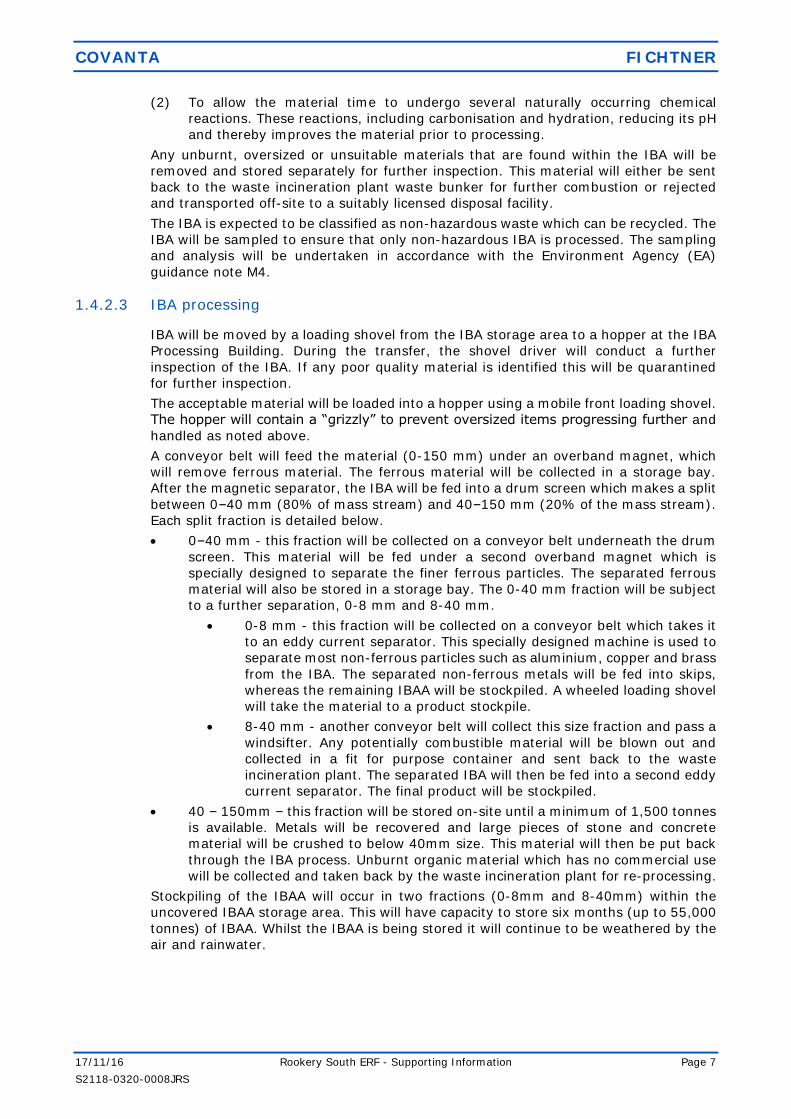
1.4.2.3 IBA processing
IBA will be moved by a loading shovel from the IBA storage area to a hopper at the IBA
Processing Building. During the transfer, the shovel driver will conduct a further
inspection of the IBA. If any poor quality material is identified this will be quarantined
for further inspection.
The acceptable material will be loaded into a hopper using a mobile front loading shovel.
The hopper will contain a “grizzly” to prevent oversized items progressing further and
handled as noted above.
A conveyor belt will feed the material (0-150 mm) under an overband magnet, which
will remove ferrous material. The ferrous material will be collected in a storage bay.
After the magnetic separator, the IBA will be fed into a drum screen which makes a split
between 0–40 mm (80% of mass stream) and 40–150 mm (20% of the mass stream).
Each split fraction is detailed below.
0–40 mm - this fraction will be collected on a conveyor belt underneath the drum
screen. This material will be fed under a second overband magnet which is
specially designed to separate the finer ferrous particles. The separated ferrous
material will also be stored in a storage bay. The 0-40 mm fraction will be subject
to a further separation, 0-8 mm and 8-40 mm.
0-8 mm - this fraction will be collected on a conveyor belt which takes it
to an eddy current separator. This specially designed machine is used to
separate most non-ferrous particles such as aluminium, copper and brass
from the IBA. The separated non-ferrous metals will be fed into skips,
whereas the remaining IBAA will be stockpiled. A wheeled loading shovel
will take the material to a product stockpile.
8-40 mm - another conveyor belt will collect this size fraction and pass a
windsifter. Any potentially combustible material will be blown out and
collected in a fit for purpose container and sent back to the waste
incineration plant. The separated IBA will then be fed into a second eddy
current separator. The final product will be stockpiled.
40 – 150mm – this fraction will be stored on-site until a minimum of 1,500 tonnes
is available. Metals will be recovered and large pieces of stone and concrete
material will be crushed to below 40mm size. This material will then be put back
through the IBA process. Unburnt organic material which has no commercial use
will be collected and taken back by the waste incineration plant for re-processing.
Stockpiling of the IBAA will occur in two fractions (0-8mm and 8-40mm) within the
uncovered IBAA storage area. This will have capacity to store six months (up to 55,000
tonnes) of IBAA. Whilst the IBAA is being stored it will continue to be weathered by the
air and rainwater.
COVANTA FICHTNER
17/11/16 Rookery South ERF - Supporting Information Page 8
S2118-0320-0008JRS
The quantities of IBAA being stored on site will be influenced by the market demand for
IBAA material. Typically, the lowest demand occurs during the winter months and the
highest during the summer months. IBAA will typically be held in the storage area for
one month prior to shipment to the construction industry to allow for fluctuations in
demand between seasons.
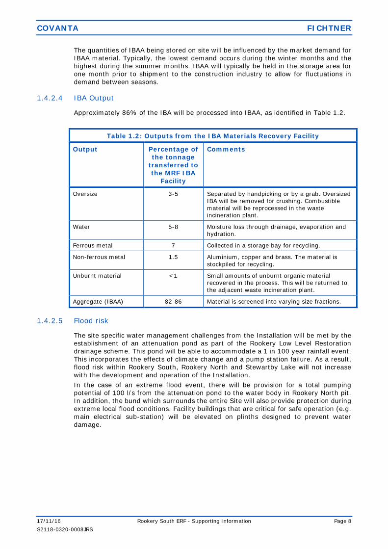
1.4.2.4 IBA Output
Approximately 86% of the IBA will be processed into IBAA, as identified in Table 1.2.
Table 1.2: Outputs from the IBA Materials Recovery Facility
Output Percentage of
the tonnage
transferred to
the MRF IBA
Facility
Comments
Oversize 3-5 Separated by handpicking or by a grab. Oversized IBA will be removed for crushing. Combustible material will be reprocessed in the waste incineration plant.
Water 5-8 Moisture loss through drainage, evaporation and hydration.
Ferrous metal 7 Collected in a storage bay for recycling.
Non-ferrous metal 1.5 Aluminium, copper and brass. The material is stockpiled for recycling.
Unburnt material <1 Small amounts of unburnt organic material recovered in the process. This will be returned to
the adjacent waste incineration plant.
Aggregate (IBAA) 82-86 Material is screened into varying size fractions.
1.4.2.5 Flood risk
The site specific water management challenges from the Installation will be met by the
establishment of an attenuation pond as part of the Rookery Low Level Restoration
drainage scheme. This pond will be able to accommodate a 1 in 100 year rainfall event.
This incorporates the effects of climate change and a pump station failure. As a result,
flood risk within Rookery South, Rookery North and Stewartby Lake will not increase
with the development and operation of the Installation.
In the case of an extreme flood event, there will be provision for a total pumping
potential of 100 l/s from the attenuation pond to the water body in Rookery North pit.
In addition, the bund which surrounds the entire Site will also provide protection during
extreme local flood conditions. Facility buildings that are critical for safe operation (e.g.
main electrical sub-station) will be elevated on plinths designed to prevent water
damage.
COVANTA FICHTNER
17/11/16 Rookery South ERF - Supporting Information Page 9
S2118-0320-0008JRS
2 OTHER INFORMATION FOR APPLICATION FORM
2.1 Raw materials
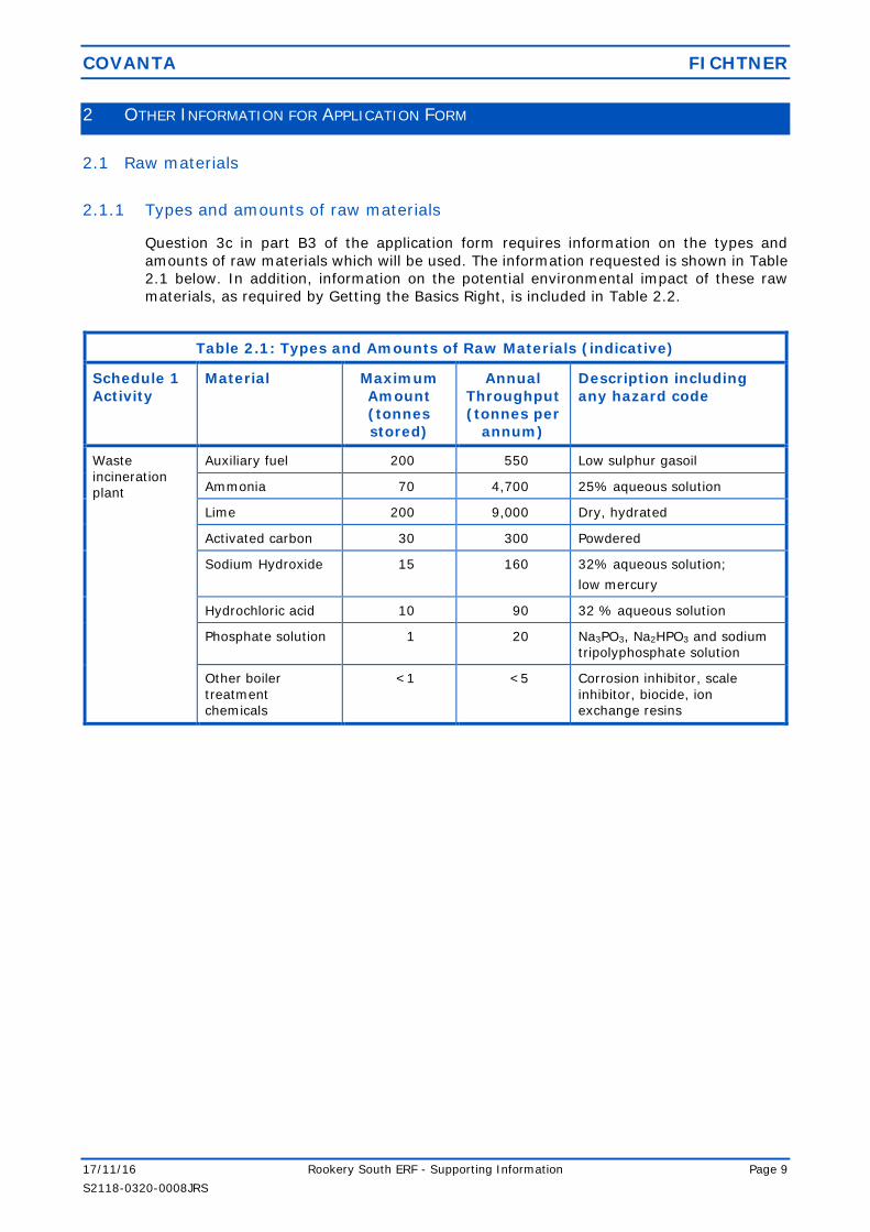
2.1.1 Types and amounts of raw materials
Question 3c in part B3 of the application form requires information on the types and
amounts of raw materials which will be used. The information requested is shown in Table
2.1 below. In addition, information on the potential environmental impact of these raw
materials, as required by Getting the Basics Right, is included in Table 2.2.
Table 2.1: Types and Amounts of Raw Materials (indicative)
Schedule 1
Activity
Material Maximum
Amount
(tonnes
stored)
Annual
Throughput
(tonnes per
annum)
Description including
any hazard code
Waste
incineration plant
Auxiliary fuel 200 550 Low sulphur gasoil
Ammonia 70 4,700 25% aqueous solution
Lime 200 9,000 Dry, hydrated
Activated carbon 30 300 Powdered
Sodium Hydroxide 15 160 32% aqueous solution;
low mercury
Hydrochloric acid 10 90 32 % aqueous solution
Phosphate solution 1 20 Na3PO3, Na2HPO3 and sodium
tripolyphosphate solution
Other boiler
treatment chemicals
<1 <5 Corrosion inhibitor, scale
inhibitor, biocide, ion exchange resins

COVANTA FICHTNER
17/11/16 Rookery South ERF - Supporting Information Page 10
S2118-0320-0008JRS
Table 2.2: Effect of Raw Materials on the Environment
Product Chemical
Composition
Typical
Quantity
Units Environmental Medium Impact
Potential
Comments
Air Land Water
Gasoil Low sulphur
(<0.1%)
550 tonnes/yr 100 Low impact Used for facility start-ups and to maintain
good combustion conditions in the boiler. Facility combustion products released to atmosphere after passing through flue gas treatment facility.
Lime Ca(OH)2 >95% 9,000 tonnes / yr 0 100 0 Low impact Injected lime is removed with the Flue Gas Treatment (FGT) residues at the bag filter
and disposed of as hazardous waste at a suitable licensed facility.
Activated Carbon
300 tonnes/yr 0 100 0 Low impact Injected carbon is removed with the APCr at the bag filter and disposed of as hazardous waste at a suitable licensed facility.
Ammonium hydroxide solution
NH4.OH 4,700 tonnes / year
100 0 00 Low impact Reacts with nitrogen oxides to form nitrogen, oxygen and water vapour. Any unreacted ammonia is released to atmosphere at low concentrations, and is continuously
monitored.
Hydrochloric Acid
HCl 32% aqueous solution
160 litres / year 0 0 100 Low impact Used for regeneration of water treatment facility. Bio-degradable, no bioaccumulation potential and negligible ecotoxicity.
Sodium Hydroxide
NaOH 32% aqueous solution,
low mercury
90 litres / year 0 0 100 Low impact Used for regeneration of water treatment facility. Bio-degradable, no bioaccumulation
potential and negligible ecotoxicity.
Phosphate solution
Na3PO3, Na2HPO3 and sodium tripolyphosphate
solution
20 tonnes / yr 0 0 0 Low impact No process water discharge. Blowdown is reused in process water system.
COVANTA FICHTNER
17/11/16 Rookery South ERF - Supporting Information Page 11
S2118-0320-0008JRS
Various other materials will be required for the operation and maintenance of the facility,
including:
hydraulic oils and silicone based oils;
electrical switchgear;
gas emptying and filling equipment;
refrigerant gases for the air conditioning plant;
oxyacetylene, TIG, MIG welding gases;
glycol/anti-freeze for cooling;
carbon dioxide (CO2), or other firefighting foam agents; and
test and calibration gases.
These will be supplied to standard specifications offered by main suppliers. All chemicals
will be handled in accordance with Control of Substances Hazardous to Health (COSHH)
Regulations as part of the quality assurance procedures and full product data sheets will
be available on site.
Periodic reviews of all materials used will be made in the light of new products and
developments. Any significant change of material, where it may have an impact on the
environment, will not be made without firstly assessing the impact and seeking approval
from the EA.
The Operator will maintain a detailed inventory of raw materials used on site and have
procedures for the regular review of new developments in raw materials.
2.1.2 Raw materials selection
2.1.2.1 Acid gas abatement
There are several reagents available for acid gas abatement. Sodium Hydroxide (NaOH)
or hydrated lime (Ca(OH)2) can be used in a wet scrubbing system. Quicklime (CaO)
can be used in a semidry FGT system. Sodium bicarbonate (NaHCO3) or hydrated lime
can be used in a dry FGT process.
The reagents for wet scrubbing and semi-dry abatement are not considered, since these
abatement techniques have been eliminated by the Best Available Technology (BAT)
assessment in Annex 5. The two alternative reagents for a dry system – lime and
sodium bicarbonate are therefore assessed further.
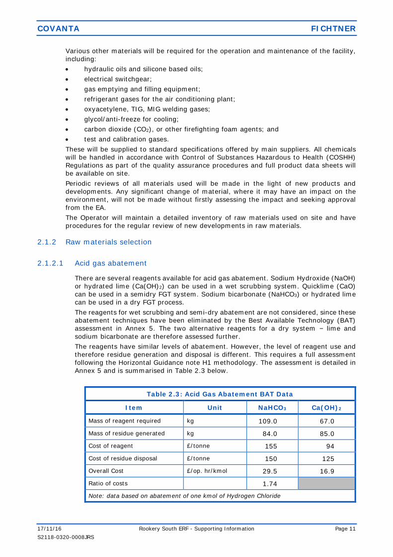
The reagents have similar levels of abatement. However, the level of reagent use and
therefore residue generation and disposal is different. This requires a full assessment
following the Horizontal Guidance note H1 methodology. The assessment is detailed in
Annex 5 and is summarised in Table 2.3 below.
Table 2.3: Acid Gas Abatement BAT Data
Item Unit NaHCO3 Ca(OH)2
Mass of reagent required kg 109.0 67.0
Mass of residue generated kg 84.0 85.0
Cost of reagent £/tonne 155 94
Cost of residue disposal £/tonne 150 125
Overall Cost £/op. hr/kmol 29.5 16.9
Ratio of costs 1.74
Note: data based on abatement of one kmol of Hydrogen Chloride

COVANTA FICHTNER
17/11/16 Rookery South ERF - Supporting Information Page 12
S2118-0320-0008JRS
There is a small environmental benefit for using sodium bicarbonate, because the mass
of residues produced is slightly smaller. However, there are a number of significant
disadvantages:
the residue has a higher leaching ability than lime-based residues, which will limit
disposal options;
the reaction temperature doesn’t match as well with the optimum adsorption
temperature for carbon;
the sodium bicarbonate system has a slightly higher global warming potential due
to the reaction chemistry (by around 1,000 tonnes of CO2); and
the costs are 74% higher.
Hence, the use of lime is considered to be BAT for this installation.
2.1.2.2 NOx abatement reagent
The SNCR system can be operated with dry urea, urea solution or aqueous ammonia
solution. There are advantages and disadvantages with all options, as follows.
Urea is easier to handle than ammonia. The handling and storage of ammonia can
introduce an additional risk.
Dry urea needs big-bags handling whereas urea solution can be stored in silos
and delivered in tankers.
Ammonia tends to generate lower nitrous oxide levels than urea. Nitrous oxide is
a potent greenhouse gas.
Ammonia emissions (or ‘slip’) can occur with both reagents, although good control
will reduce the risk of this issue.
The Sector Guidance on Waste Incineration considers all options as suitable for NOx
abatement. It is proposed to use aqueous ammonia for the SNCR system, because the
climate change impacts of urea outweigh the handling and storage issues associated
with ammonia solution. These issues can be overcome by good design of the ammonia
tanks and pipework and the use of suitable procedures for the delivery of ammonia.
2.1.2.3 Auxiliary fuel
As stated in Article 50 (3) of the Industrial Emissions Directive (IED):
The auxiliary burner shall not be fed with fuels which can cause higher emissions
than those resulting from the burning of gas oil as defined in Article 2(2) of Council
Directive 1999/32/EC of 26 April 1999 relating to a reduction in the sulphur
content of certain liquid fuels (1) OJ L 121, 11.5.1999, p. 13., liquefied gas or
natural gas.
Therefore, as identified by the requirements of the IED, the only available fuels that can
be used for auxiliary firing are:
(1) natural gas;
(2) liquefied gas (LPG); or
(3) gas oil.
Natural gas can be used for auxiliary firing and is safer to handle than LPG. As stated
previously, auxiliary firing will only be required intermittently. When firing this requires
large volumes of gas, which would be need to be supplied from a high-pressure gas
main. The installation of a high-pressure gas main to supply gas for auxiliary firing to
the Installation would be very expensive.
COVANTA FICHTNER
17/11/16 Rookery South ERF - Supporting Information Page 13
S2118-0320-0008JRS
LPG is a flammable mixture of hydrocarbon gases. It is a readily available product, and
can be used for auxiliary firing. As LPG turns gaseous under ambient temperature and
pressure, it is required to be stored in purpose built pressure vessels. If there was a fire
within the site, there would be a significant explosion risk from the combustion of
flammable gases stored under pressure.
A gas oil tank can be easily installed at the Installation. Whilst it is acknowledged that
gas oil is classed as flammable, it does not pose the same type of safety risks as those
associated with the storage of LPG. The combustion of gas oil will lead to emissions of
sulphur dioxide, but these emissions will be minimised as far as reasonably practicable
through the use of low sulphur gas oil.
Therefore, low sulphur light gas oil will be used for auxiliary firing.
2.2 Incoming waste management
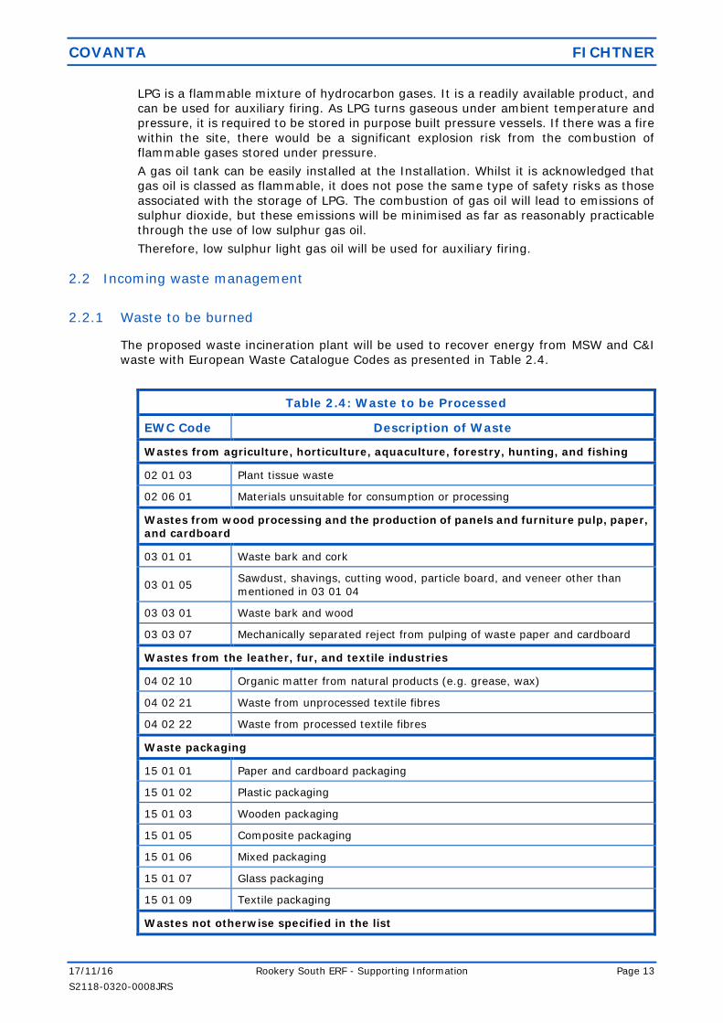
2.2.1 Waste to be burned
The proposed waste incineration plant will be used to recover energy from MSW and C&I
waste with European Waste Catalogue Codes as presented in Table 2.4.
Table 2.4: Waste to be Processed
EWC Code Description of Waste
Wastes from agriculture, horticulture, aquaculture, forestry, hunting, and fishing
02 01 03 Plant tissue waste
02 06 01 Materials unsuitable for consumption or processing
Wastes from wood processing and the production of panels and furniture pulp, paper, and cardboard
03 01 01 Waste bark and cork
03 01 05 Sawdust, shavings, cutting wood, particle board, and veneer other than
mentioned in 03 01 04
03 03 01 Waste bark and wood
03 03 07 Mechanically separated reject from pulping of waste paper and cardboard
Wastes from the leather, fur, and textile industries
04 02 10 Organic matter from natural products (e.g. grease, wax)
04 02 21 Waste from unprocessed textile fibres
04 02 22 Waste from processed textile fibres
Waste packaging
15 01 01 Paper and cardboard packaging
15 01 02 Plastic packaging
15 01 03 Wooden packaging
15 01 05 Composite packaging
15 01 06 Mixed packaging
15 01 07 Glass packaging
15 01 09 Textile packaging
Wastes not otherwise specified in the list

COVANTA FICHTNER
17/11/16 Rookery South ERF - Supporting Information Page 14
S2118-0320-0008JRS
16 03 04 Off-specification batches – inorganic
16 03 06 Off specification batches – organic
Construction and demolition wastes
17 02 01 Wood
17 02 03 Plastic
17 09 04 Mixed construction and demolition wastes other than those mentioned in 17 09 01, 17 09 02, and 17 09 03
Wastes from human or animal health care and/or related research (except kitchen and restaurant wastes not arising from immediate health care)
18 01 04 Wastes whose collection and disposal is not subject to special requirements in order to prevent infection
18 02 03 Wastes whose collection and disposal is not subject to special requirements
in order to prevent infection
Waste from waste and water treatment
19 02 03 Premixed wastes composed only of non-hazardous wastes
19 05 01 Non-composted fraction of municipal and similar wastes
19 05 02 Waste aerobic treatment of solid wastes from non-composted fraction of animal and vegetable waste
19 05 03 Off-specification compost
19 06 04 Digestate from aerobic treatment of municipal waste
19 06 06 Digestate from anaerobic treatment of animal and vegetable waste
19 12 01 Paper and cardboard
19 12 04 Plastic and rubber
19 12 07 Wood
19 12 08 Textiles
19 12 10 Combustible waste (refuse derived fuel)
19 12 12 Other wastes (including mixtures of materials) from mechanical treatment of wastes other than those mentioned in 19 12 11
Municipal wastes
20 01 01 Paper and cardboard
20 01 08 Kitchen and canteen waste
20 01 10 Clothes
20 01 11 Textiles
20 01 38 Wood
20 01 39 Plastics
20 02 01 Biodegradable waste
20 03 01 Mixed municipal waste
20 03 02 Waste from markets
20 03 03 Street cleaning residues

COVANTA FICHTNER
17/11/16 Rookery South ERF - Supporting Information Page 15
S2118-0320-0008JRS
20 03 04 Residual sludge from septic tanks and other similar installations for the
treatment of sewage only (could also include sewage undertaker sludge disposal)
20 03 07 Bulky waste
The waste incineration plant is expected process a nominal 585,000 tonnes per year, is
based on an NCV of 9.3 MJ/kg, with an assumed annual availability of 7,800 hours per
annum.
Hours of operation will affect total fuel input capacity. On certain occasions waste
throughput may be increased due to good facility performance and a reduction in planned
shut-down frequency.
The waste will be delivered from the local area in Refuse Collection Vehicles (RCVs) and
by Bulk Transfer Vehicles (BTVs). Checks will be made on the paperwork accompanying
each delivery to ensure that only waste for which the waste incineration plant has been
designed will be accepted at the Rookery South ERF.
It may not be practical to inspect compressed waste deliveries found within the RCVs or
BTVs. The waste will be randomly inspected by the tipping hall operator as it is tipped
followed by the crane driver and control room operator as it is mixed. Unacceptable waste
will be removed from the bunker and quarantined for further inspection in a designated
area within the tipping hall. Commercial and industrial waste will have spot check
inspections prior to tipping into the bunker.
2.2.2 Waste handling
Covanta will develop pre-acceptance and acceptance procedures which comply with the
Indicative BAT requirements in the Sector Guidance Note, including:
A high standard of housekeeping will be maintained in all areas and provide and
maintaining suitable equipment to clean up spilled materials.
Loading and unloading of vehicles will take place in designated areas provided with
impermeable hard standing. These areas will have appropriate falls to the process
water drainage system.
Fire fighting measures will be designed in accordance with the requirements of the
Fire Prevention Plan (refer to Annex 8).
Delivery and reception of waste will be controlled by a management system that will
identify all risks associated with the reception of waste and shall comply with all
legislative requirements, including statutory documentation.
Incoming waste will be:
delivered in covered vehicles or containers; and
unloaded in the enclosed waste reception areas.
Design of equipment, buildings and handling procedures will ensure there is
insignificant dispersal of litter.
Inspection will take place by the plant operatives during vehicle tipping and waste
unloading.
2.2.3 Waste minimisation (minimising the use of raw materials)
A number of specific techniques will be employed to minimise the production of residues,
focussing on the following:
(1) Feedstock Homogeneity;
(2) Dioxin & Furan Reformation;
(3) Furnace Conditions;
(4) Flue Gas Treatment Control; and
COVANTA FICHTNER
17/11/16 Rookery South ERF - Supporting Information Page 16
S2118-0320-0008JRS
(5) Waste Management.
All of these techniques meet the Indicative BAT requirements from the Sector Guidance
Note on Waste Incineration.
2.2.3.1 Feedstock Homogeneity
Improving feedstock homogeneity can improve the operational stability of the plant,
leading to reduced reagent use and reduced residue production. The incoming waste
which is delivered into the waste bunker will be mixed by the cranes within the bunker.
The mixing of the waste will improve the homogeneity of the fuel input to the waste
incineration plant.
2.2.3.2 Dioxin & Furan Reformation
As identified within the sector guidance for the Incineration of Waste (EPR5.01), there
are a number of BAT design considerations required for the boiler. The waste
incineration boiler has been designed to minimise the formation of dioxins and furans
as follows:
Slow rates of combustion gas cooling will be avoided via boiler design to ensure
the residence time is minimised in the critical cooling section and avoid slow rates
of combustion gas cooling to minimise the potential for de-novo formation of
dioxins and furans.
The gas residence time in the critical temperature range will be minimised by
ensuring high gas velocities exist in these sections. The residence time and
temperature profile (between 450 and 200oC) of flue gas will be considered during
the detailed design phase to ensure that dioxin formation is minimised throughout
the process.
It is reported in the EA guidance note EPR5.01 that the injection of ammonia
compounds into the furnace – an SNCR NOx abatement system – inhibits dioxin
formation and promotes their destruction. SNCR is to be utilised in the waste
incineration plant.
Computerised Fluidised Dynamics (CFD) will be applied to the design, where
considered appropriate, to ensure gas velocities are in a range that negates the
formation of stagnant pockets / low velocities. A copy of the CFD model will be
supplied to the EA following detailed design and prior to commencement of
commissioning.
Minimising the volume in the critical cooling sections will ensure high gas
velocities.
Boundary layers of slow moving gas along boiler surfaces will be prevented via
design and a regular maintenance schedule to remove build-up of any deposits
that may have occurred.
2.2.3.3 Furnace Conditions
Furnace conditions will be optimised in order to minimise the quantity of residues arising
for further disposal. Burnout in the furnace will reduce the Total Organic Carbon (TOC)
content of the bottom ash to less than 3% by optimising waste feed rate and combustion
air flows utilising ASTM D 5468 Standard Test Method for Gross Calorific and Ash Value
of Waste Materials.
2.2.3.4 Flue Gas Treatment Control
Close control of the flue gas treatment system will minimise the use of reagents and
hence minimise the APCr produced. SNCR reagent dosing will be optimised to prevent
ammonia slip.

COVANTA FICHTNER
17/11/16 Rookery South ERF - Supporting Information Page 17
S2118-0320-0008JRS
Lime usage will be minimised by trimming reagent dosing to accurately match the acid
load using fast response upstream acid gas monitoring. The plant preventative
maintenance regime will include regular checks and calibration of the reagent dosing
system to ensure optimum operation. Back-up feed systems will be provided to
minimize interruption in lime dosing. The bag filter is designed to build up a filter cake
of unreacted acid gas reagent, which acts as a buffer during any minor interruptions in
dosing.
Activated carbon dosing will be based on demonstrated performance to achieve IED
emission limits. Activated carbon will be controlled by a gravimetric feeder to ensure a
dosing that has complied with IED emission limits. Maintaining a steady minimum
concentration of activated carbon in the flue gas and consequently on the filter bags will
maintain the adsorption rate for gaseous metals and dioxins.
Activated carbon and lime will be stored in separate silos. The feed rate for the activated
carbon and lime dosing systems will be controlled separately.
2.2.3.5 Waste Charging
The waste incineration plant will meet the indicative BAT requirements outlined in the
Incinerator Sector Guidance Note for fuel charging and the specific requirements of the
IED:
The combustion control and feeding system will be fully in line with the
requirements of the IED. The conditions within the furnace will be continually
monitored to ensure that optimal conditions are maintained and that the
mandatory IED emission limits are not exceeded. Auxiliary burners fired with gas
oil will be installed and will be used to maintain the temperature in the combustion
chamber;
The waste charging and feeding systems will be interlocked with furnace
conditions so that charging cannot take place until combustion temperatures of
850°C are achieved, during start-up;
The waste charging and feeding systems will also be interlocked with the
continuous emissions monitoring system to prevent waste charging if the
emissions to atmosphere are in excess of an emission limit value for more than
four (4) consecutive hours, as allowable in accordance with the conditions relating
to abnormal operation;
Following loading into the feeding chutes by the grab, the waste will be transferred
onto the grates by hydraulic powered feeding units;
The backward flow of combustion gases and the premature ignition of waste will
be prevented by keeping the chute full of waste and by keeping the furnace under
negative pressure;
A level detector will monitor the amount of waste in the feed chute and an alarm
will be sounded if the fuel falls below the safe minimum level. Secondary air will
be injected from nozzles in the wall of the furnace to control flame height and the
direction of air and flame flow; and
In a breakdown scenario, operations will be reduced or closed down as soon as
practicable until normal operations can be restored.
The feed rate to the furnace will be controlled by the combustion control system.
2.3 Water use
It is anticipated that the Rookery South ERF will consume approximately 12 m3/hr of towns
water. The principal uses of water within the Rookery South ERF will be as boiler feedwater
and the ash quench. The water system has been designed to minimise the consumption of
potable water and ensure zero discharge of process water. Feedwater for the ash quench will
be supplemented by process effluents generated from the Rookery South ERF.

COVANTA FICHTNER
17/11/16 Rookery South ERF - Supporting Information Page 18
S2118-0320-0008JRS
An indicative water schematic for the Rookery South ERF is presented Figure 2. A larger
version is presented in Annex 1.
Figure 2 – Indicative Water Flow Diagram
2.3.1 Surface water
Surface water from the roofs of buildings at the Rookery South ERF will be collected in a
rainwater storage tank for use within the IBA Quench System. In the event of imminent
overflow of the storage tank, an outlet valve system will drain controlled quantities of water
through an interceptor into the storm drains.
All other surface water (roadways and areas of hardstanding) shall be collected in drains
with oily water interceptors which will incorporate an isolating penstock valve installed on
the discharge pipe. This water will then be discharged via an interceptor channel into an
attenuation pond to be constructed as part of the Rookery Low Level Restoration drainage
scheme. This pond will be located adjacent to the Rookery South ERF, in the north-west
corner of the Installation.
The discharge from the interceptors will be tested periodically to verify that it is not
contaminated. The drainage system, interceptor and penstock valve will be subject to a
planned maintenance regime.
2.3.2 Process water
2.3.2.1 Steam boiler
Towns Water will be treated using a package demineralisation plant to produce quality
feed water for the boiler.

COVANTA FICHTNER
17/11/16 Rookery South ERF - Supporting Information Page 19
S2118-0320-0008JRS
The majority of steam exiting the turbine will be condensed to water and returned to
the boiler via an economiser.
The remaining steam lost from the boiler will be as blowdown to prevent the build-up
of sludge and chemicals, in addition to system leaks and miscellaneous system vents
(e.g., deaerator) and drains. Boiler blowdown water will be collected in the Dirty Water
Tank. Lost steam cycle water will be replaced with demineralised Towns water.
2.3.2.2 Demineralisation plant
The demineralisation plant will be located at the waste incineration plant. The
demineralisation plant is designed to remove contaminants from water through reverse
osmosis Reject water will be used within the process..
The demineralisation plant will have two treatment streams which typically run in series
but can also operate in parallel with sufficient storage capacity such that continuous
operation is maintained whilst the other is re-generating..
2.3.2.3 Dirty Water Tank
Waste process water will be collected in the Dirty Water Tank and then pumped to the
Ash Quench System.
Under normal operating conditions, waste water is generated from the following
processes:
process effluent collected in site drainage system (e.g. boiler blowdown);
reject water from the demineralised water treatment plant;
effluent generated through washdown and maintenance procedures;
water run-off collected from the Ash Quench System which is re-used within the
ash quench;
rainwater from the roofs of waste incineration plant buildings; and
surface water from the IBA MRF.
In the event of an overflow from any on-site tanks and equipment, the water will be
directed via the process water drains to the Dirty Water Tank.
The control of the water level within the Dirty Water Tank will be automatic and
continuous. The control system will ensure that Towns Water is only taken when the
Dirty Water Tank level reaches a minimum and harvested rainwater is not available (i.e.
when the rainwater tank is at minimum level).
The Dirty Water Tank will provide settlement of the re-circulated IBA quench water.
Sludge tankers will periodically remove the settled ash and sludge from the Dirty Water
Tank for transfer off-site for disposal.
2.3.2.4 Ash Quench System
To minimise the use of Towns Water, clean rainwater collected in the storage tank will
be used in the Ash Quench System when possible.
2.3.2.5 IBA water use
Surface water run-off originating from the IBA facility will include rainwater and run-off
from roadways, areas of hardstanding and stockpile areas. This surface water will be
directed towards a run-off lagoon located along the northern boundary of the Rookery
South ERF.

COVANTA FICHTNER
17/11/16 Rookery South ERF - Supporting Information Page 20
S2118-0320-0008JRS
Surface water will pass through a catch pit before entering the lagoon. This will remove
solids that may be present in the run-off. The lagoon will allow suspended solids to
settle. There will be regular monitoring of settled solids levels within the catch pit and
lagoon. When the catch pit reaches a high level of solids it will be dewatered to allow
the solids to be emptied. The catch pit is designed to allow a front loading shovel to
enter and remove the captured silt. When high levels of silt are found in the lagoon,
these will be removed by a gulley sucker. Following removal of the silt, it will be
transferred to the IBA MRF building. If this is not possible, the material will be removed
from site using a licensed waste carrier and transported to a suitably licensed facility
for disposal/recovery.
Under normal conditions the surface water collected in the run-off lagoon will be used
for dust suppression at the IBA facility. Run-off from this process will be directed back
to the lagoon.
Under unusual conditions (such as periods of high rainfall or shutdown of the waste
incineration plant), the water within the lagoon will be collected in a tanker, and
transferred off-site for disposal at a suitably licensed facility.
2.3.2.6 Other uses
Towns water will supply the office and mess facilities within the Rookery South ERF.
Waste water from these facilities will be treated at the on-site effluent treatment plant
prior to discharge into the Low Level Restoration Scheme.
Water for firefighting will be sourced from Towns Water and stored on-site in tanks with
a dedicated pump set.
2.3.3 Site Drainage
The waste incineration plant buildings are designed with a sustainable drainage
management scheme to collect and contain process water within buildings and ensure
surface water is not contaminated. This will consist of a sloped floor gulley and piped drain
system, connected to a centralised reuse water storage tank (Dirty Water Tank).
During the commissioning period for the ERF the drainage system will be subject to testing
prior to commencing the operational phase. Records for commissioning of the drainage
systems will be made available to the EA for inspection.
The drainage system will be designed and operated in accordance with:
EA PPG1 - General guide to the prevention of pollution;
EA PPG2 - Above Ground Oil Storage Tanks;
EA PPG 21 - Incident Response Planning; and
EA PPG 22 - Dealing with spills.
Construction Industry Research and Information Association (CIRIA) Report 164 “Design
of Containment Systems for the Prevention of Water Pollution from Industrial Incidents”.
2.3.3.1 Spillage management
The Rookery South ERF has been designed to contain water used for firefighting or any
chemicals/materials in the event of a spillage. All chemical and fuel storage vessels will
be located in a bunded area to contain spillage or leaks. All process areas will be located
on hard standing with no direct drainage connection to the surface water drainage
systems. If there is a spillage, it will be contained either within the storage tank bund
or the process water drainage network.
COVANTA FICHTNER
17/11/16 Rookery South ERF - Supporting Information Page 21
S2118-0320-0008JRS
Good housekeeping practices will be in operation to ensure that any spillages are cleared
up at the earliest opportunity. Spill kits will be available for the clean-up of all chemicals
and oils stored and used within the Rookery South ERF. Spill kits will be located in close
proximity to the relevant materials handling, loading/unloading and storage areas. The
spill kits will be used to contain the spillage and prevent any release of pollution to the
drainage system. Spillage control procedures developed prior to commencement of
commissioning will detail those actions to be followed in the event of a spillage.
No material will be discharged on the internal road network which could potentially
contaminate surface water run-off. Under normal operating conditions materials will be
delivered to and from the waste incineration plant in dedicated transport vehicles by
competent delivery drivers. Pollution prevention measures and strict operational
controls will ensure that internal roadway rainwater run-off remains uncontaminated
from process materials from the waste incineration plant. A trained member of
Covanta’s operational team will be in attendance during the delivery and off-loading of
all chemicals and fuels.
In an emergency condition, such as a spillage or vehicle accident, the surface water
discharge penstock valves will be closed. Any spillage or leak on the road network will
be isolated, retained and remediated locally following the waste incineration plant spill
procedure. The penstock valve will retain all surface water run-off within the drainage
system to prevent its release to the environment. The retained surface water run-off
will be tested and transferred off-site to an appropriately permitted waste management
facility. If necessary, the drainage system and interceptor will be emptied and cleaned
prior to the penstock valve being opened to allow the discharge of uncontaminated rain
water.
2.4 Emissions
2.4.1 Emissions to air
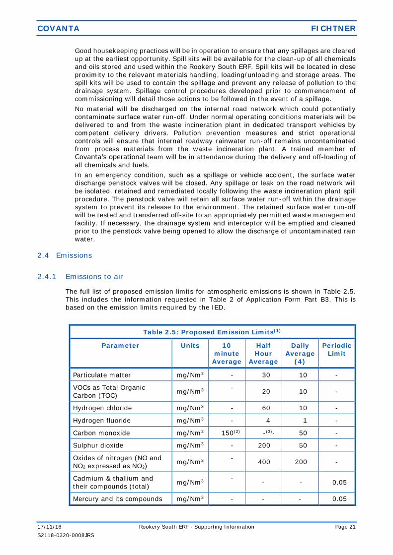
The full list of proposed emission limits for atmospheric emissions is shown in Table 2.5.
This includes the information requested in Table 2 of Application Form Part B3. This is
based on the emission limits required by the IED.
Table 2.5: Proposed Emission Limits(1)
Parameter Units 10
minute
Average
Half
Hour
Average
Daily
Average
(4)
Periodic
Limit
Particulate matter mg/Nm3 - 30 10 -
VOCs as Total Organic
Carbon (TOC) mg/Nm3
- 20 10 -
Hydrogen chloride mg/Nm3 - 60 10 -
Hydrogen fluoride mg/Nm3 - 4 1 -
Carbon monoxide mg/Nm3 150(2) -(3)- 50 -
Sulphur dioxide mg/Nm3 - 200 50 -
Oxides of nitrogen (NO and
NO2 expressed as NO2) mg/Nm3
- 400 200 -
Cadmium & thallium and
their compounds (total) mg/Nm3
- - - 0.05
Mercury and its compounds mg/Nm3 - - - 0.05

COVANTA FICHTNER
17/11/16 Rookery South ERF - Supporting Information Page 22
S2118-0320-0008JRS
2.4.2 Odour
The storage and handling of waste is considered to have potential to give rise to odour.
The facility will be designed in accordance with the requirements of EA Guidance Note H4:
Odour.
Waste Storage
Waste storage areas will be designed such that there is air flow into the building, with air
from the waste reception and bunker areas being utilised as combustion air within the ERF.
Fuel reception and storage areas will utilise a dust suppression system; this is a sprinkler
type system, which will emit a very fine spray to suppress dust, if necessary.
Overall Design
The main access doors to the reception area will used for the waste delivery vehicles will
be kept closed except during vehicles coming in and leaving to maintain odour control
during delivery times.
As the waste incineration plant is a three stream facility, it will ensure that the waste
storage areas will continuously be maintained at a negative pressure, even during
shutdown of a single line.
Management Controls
The Rookery South ERF will include the following management controls for odour:
during shutdown, doors will limit odour spread while still allowing vehicle access.
Misting sprays may be used to reduce odour from the fuel bunker; and
bunker management procedures and good mixing will be employed at the waste
incineration plant to minimise the development of anaerobic conditions.
2.4.3 Emissions to water
There will be no process emissions to water. Wastewaters from the process will be collected
and re-utilized.
All areas of hardstanding within the IBA will be profiled so that surface water run-off from
areas subject to potential ash contamination is collected.
Clean water such as rainwater from roofs will be collected in a rainwater storage tank and
utilised within the waste incineration plant or IBA facility or released through an interceptor
into the storm drains. Surface water from roadways and areas of hardstanding will pass
through an oil/silt interceptor prior to being discharged into the Low Level Restoration
Scheme (LLRS) attenuation pond.
Sb, As, Pb, Cr, Co, Cu, Mn,
Ni and V and their
compounds (total)
mg/Nm3
-
- - 0.5
Dioxins & furans ITEQ ng/Nm3 - - - 0.1
Note:
(1) all concentrations expressed at 11% oxygen, dry flue gas, at 0°C and 1 bar-a.
Limitations are not applicable during startup, shutdown or abnormal operating
conditions.
(2) Applies to a minimum of 95% of all measurements determined as a 10 minute
average
(3) Alternate to the 10 minute CO standard which is applicable to all half hour averages
on a daily basis
(4) Values of the 95% confidence interval for this averaging period shall not exceed
the WID Annex III percentages for each respective emission limit

COVANTA FICHTNER
17/11/16 Rookery South ERF - Supporting Information Page 23
S2118-0320-0008JRS
2.4.4 Contaminated water
All chemicals will be stored in a bunded environment supported by other measures (such
as acid and alkali resistant coatings) to ensure appropriate containment. Operational
control procedures and the bunding will reduce the potential for uncontrolled releases and
associated environmental impacts.
Adequate quantities of spillage absorbent materials will be available onsite. These will be
located at appropriate, accessible locations near to liquid storage areas. A site drainage
plan which includes the locations of foul and surface water drains and interceptors will be
made available onsite. Water interceptors will have penstock valves to prevent the
discharge of contaminated surface water in case of an incident on site.
The off-loading of diesel and ammonia water will take place within contained areas. The
storage tanks will be bunded at 110% of the tank capacity and the offloading location will
be fully contained.
Any spillage, no matter how minor, will be reported and recorded in the Accident Log for
further investigation. Site reviews will be followed in accordance with site inspection, audit
and reporting procedures. Relevant authorities (EA/Health and Safety Executive) will be
informed if spillages are over a certain volume threshold, as specified in the facility control
procedures.
The effectiveness of the Emergency Response Procedures for spillages will be reviewed
during planned drills and will be subject to Management Review.
2.4.5 Fugitive Emissions from IBA Storage
Good housekeeping practices will be implemented to ensure that any IBA spillage that
does occur is cleaned up at the earliest opportunity. Spill kits will be available for the clean-
up of IBA spills as procedures in the Quality and Environmental Management System (EMS)
require ash spills to be cleaned up promptly.
Water released from the IBA will be also prevented from entering surface water drains
through preventative maintenance, monitoring, housekeeping, and strict operational
controls.
Any heavy metals within the IBA will be present as salts. These salts will be retained in
solution when mixed with water and would not be expected to dissolve. Metals would be
retained in solution form if there was an IBA spill on the internal roadways or other areas
of hardstanding. If the IBA were to enter the surface water drainage system, it would
collect within the interceptors in the surface water drainage systems for the waste
incineration plant. The interceptors are designed to prevent the discharge of suspended
solids and oils and grease.
2.5 Emissions monitoring
Sampling and analysis of all pollutants including dioxins and furans will be carried out to CEN
or equivalent standards (e.g. ISO, national, or international standards). This ensures data
provision of an equivalent scientific quality.
The facility will be equipped with modern monitoring and data logging devices which will
enable the checking of process efficiency.
The purpose of emission monitoring has three main objectives, as follows.
(1) To provide the information necessary for efficient and safe facility operation.
(2) To warn the operator if emissions deviate from predefined ranges.
(3) To provide records of emissions and events to demonstrate regulatory compliance.
2.5.1 Monitoring emissions to air
The following substances will be monitored and recorded continuously at the stack (APC
outlet) using a Continuous Emissions Monitoring System (CEMS):
COVANTA FICHTNER
17/11/16 Rookery South ERF - Supporting Information Page 24
S2118-0320-0008JRS
particulates;
carbon monoxide (CO);
ammonia (NH3);
sulphur dioxide (SO2)
hydrogen chloride (HCl);
oxygen (O2);
nitrogen oxides (NOx); and
total organic carbon (TOC).
Temperature, water content and pressure shall also be measured to allow for correction of
the raw emission data to the required reference conditions. There will be a duty Continuous
Emissions Monitoring System (CEMS) for each line and one stand-by CEMS which can be
switched to any of the three lines. This will ensure that there is continuous monitoring data
available even if there is a problem with any of the duty CEMS systems.
The continuously monitored emissions concentrations will also be checked by an
independent testing company at frequencies agreed with the EA.
The following parameters will also be monitored by means of spot sampling:
hydrogen fluoride;
metals – cadmium (Cd), thallium (Tl), mercury (Hg), antimony (Sb), arsenic (As),
lead (Pb), chromium (Cr), cobalt (Co), copper (Cu), manganese (Mn), nickel (Ni),
vanadium (V);
organic compounds;
dioxins and furans; and
dioxin like PCBs.
Periodic measurements will be carried out four times in the first year and twice per year
thereafter.
The methods and standards used for emissions monitoring will be in compliance with
guidance note EPR5.01 and IED. The CEMS equipment will be certified to the EA's
Monitoring Certification Scheme (MCERTS) standard. It will have certified ranges which are
no greater than 1.5 times the relevant daily average emission limit.
It is anticipated that:
HCl, CO, SO2, NOx (NO and NO2) and NH3 will be measured by an FTIR type multi-
gas analyser;
VOCs (reported as TOC) will be measured by a FID type analyser;
particulate matter will be measured by an opacimeter; and
O2 will be monitored by a zirconium probe.
The periodic measurements will comply as a minimum with the requirements of the IED.
Flue gas sampling techniques and sampling platforms will comply with EA Technical
Guidance Notes M1 and M2.
2.5.1.1 Reliability
The IED allows a valid daily average to be obtained only if no more than 5 half-hourly
averages during the day are discarded due to malfunction or maintenance of the
continuous measurement system. The IED also requires that no more than 10 daily
averages are discarded per year.
These reliability requirements will be met primarily by selecting MCERTS certified
equipment.
Calibration will be carried out at intervals recommended by the manufacturer and by
the requirements of BS EN14181. The CEMS will be supplied with remote access which
will allow service engineers to provide remote diagnostics.

COVANTA FICHTNER
17/11/16 Rookery South ERF - Supporting Information Page 25
S2118-0320-0008JRS
There will be a duty CEMS for each line and one stand-by CEMS which can be switched
to any of the three lines. This will ensure that there is continuous monitoring data
available even if there is a problem with the duty CEMS system.
2.5.1.2 Start-up and shutdown
The emission limit values under the IED do not apply during start-up and shutdown
when the facility is incinerating waste. Therefore, under these conditions, a signal would
be sent from the main facility control system to the CEMS package indicating that the
facility is not operational and not burning waste. Averages for compliance with the IED
would only be calculated when this signal is sent. Raw monitoring data would be
retained for inspection.
Start-up ends when all of the following conditions are met:
the feed chute damper open, feeder ram, grate and ash extractors are all running;
exhaust gas O2 is less than 15% (wet measurement); and
the combustion grate is fully covered with waste.
Shutdown begins when all of the following conditions are met:
the feed chute damper is closed;
shutdown burner is in service; and
exhaust gas O2 is equal or above than 15% (wet measurement).
2.5.2 Monitoring emissions to land
Disposal of residues to land will comply with all relevant legislation. In particular the IBA
will comply with the IED criterion of Total Organic Carbon (TOC) less than 3%. Compliance
with the TOC criterion will be demonstrated during commissioning and checked at periodic
intervals. These frequencies will be agreed with the EA throughout the life of the facility.
Testing for TOC will be conducted by an independent accredited laboratory utilising ASTM
D 5468 Standard Test Method for Gross Calorific and Ash Value of Waste Materials.
2.5.3 Monitoring emissions to water
As discussed in Section 2.4.3, there will be no process emissions to water and the only
emissions to water will be of uncontaminated rainwater. Therefore, there will be no
requirement to undertake monitoring of emissions to water.
2.5.4 Monitoring emissions from the IBA facility
Quantitative sampling analysis of perimeter dust will be carried out via sticky discs to
monitor dusts emissions migrating from the IBA facility.
2.5.5 Waste Incineration Plant Process Monitoring
The waste incineration plant will be controlled from a dedicated control room. A modern
control system, incorporating the latest advances in control and instrumentation
technology, will be used to control operations, optimising the process relative to efficient
heat release, good burn-out and minimum particle carry-over. The system will control
and/or monitor the main features of the plant operation including, but not limited to the
following:
Combustion air;
Fuel feed rate;
SNCR system;
Flue gas oxygen concentration at the boiler exit;
Flue gas composition at the stack;

COVANTA FICHTNER
17/11/16 Rookery South ERF - Supporting Information Page 26
S2118-0320-0008JRS
Combustion process;
Boiler feed pumps and feedwater control;
Steam flow at the boiler outlet;
Steam outlet temperature;
Boiler drum level control;
Flue gas control;
Power generation; and
Steam turbine exhaust pressure.
The response times for instrumentation and control devices will be designed to be fast
enough to ensure efficient control.
The following process variables have particular potential to influence emissions:
(1) Fuel throughput will be recorded to enable comparison with the design throughput.
As a minimum, monthly and annual throughput will be recorded; Steam generation
rates will be recorded to enable comparison for short term design throughput.
(2) Combustion temperature will be monitored at a suitable position to demonstrate
compliance with the requirement for a residence time of 2 seconds at a temperature
of at least 850°C;
(3) The differential pressure across the bag filters will be measured, in order to optimise
the performance of the cleaning system and to detect bag failures; and
(4) The concentration of HCl and SO2 in the flue gases upstream of the flue gas treatment
system and other emission and process parameters will be monitored, to optimise
the performance of the emissions abatement equipment dependent on specific
vendor design.
Water use will be monitored and recorded regularly at various points throughout the
process to help highlight any abnormal usage. This will be achieved by monitoring the
incoming water supplies and the boiler water makeup.
In addition, electricity and auxiliary fuel consumption will be monitored to highlight any
abnormal usage.
Validation of Combustion Conditions
The waste incineration plant will be designed to provide a residence time, after the last
injection of combustion air, of more than two seconds at a temperature of at least 850°C.
This criterion will be demonstrated using Computational Fluid Dynamic (CFD) modelling
during the design stage and confirmed by the recognized measurements and
methodologies during commissioning in accordance with Guidance Note EPR5.01.
It will also be demonstrated during commissioning that the waste incineration plant can
achieve complete combustion by measuring concentrations of carbon monoxide, VOCs and
dioxins in the flue gases and TOC of the bottom ash.
During the operational phase, the temperature at the 2 seconds residence time point will
be monitored to ensure that it remains above 850°C. The location of the temperature
probes will be selected using the results of the CFD model. If it is not possible to locate
the temperature probes at precisely the 2 seconds residence time point then a correction
factor will be applied to the measured temperature. The CFD model for the design will be
made available to the EA following detailed design of the boiler.
Ammonia solution will be injected into the flue gases at a temperature of between 850 and
1000°C. This narrow temperature range is needed to reduce NOx successfully and avoid
unwanted secondary reactions. This means that multiple levels of injection points will be
required in the radiation zone of the furnace.
Sufficient nozzles will be provided at each level to distribute the ammonia correctly across
the entire cross section of the radiation zone. CFD modelling will be used to define the
appropriate location and number of injection levels as well as number of nozzles to make
sure the SNCR system achieves the required reduction efficiency for the whole range of
operating conditions while maintaining the ammonia slip below the required emission level.

COVANTA FICHTNER
17/11/16 Rookery South ERF - Supporting Information Page 27
S2118-0320-0008JRS
The CFD modelling will also be used to optimise the location of the secondary air inputs
into the combustion chamber.
Measuring Oxygen Levels
The oxygen concentration at the boiler exit of the waste incineration plant will be monitored
to ensure that there will always be adequate oxygen for complete combustion of
combustible gases.
2.6 Technology selection
2.6.1 Combustion technology
It is proposed that the waste incineration plant combustion technology will be a modern
moving grate and furnace/boiler.
This is the leading technology in the UK and Europe for the combustion of untreated
Municipal Solid Waste (MSW). The moving grate comprises of fixed and moving bars that
will move the waste from the feed inlet to the residue discharge. The grate movement
turns and mixes the waste along the surface of the grate to ensure that all waste is exposed
to the combustion process.
The Incinerator Sector Guidance Note discusses a number of alternative technologies for
the combustion of waste.
Moving Grate Furnaces
As stated in the Sector Guidance Note, these are designed to handle large volumes of
waste.
Fixed Hearth
These are not considered suitable for large volumes of waste. They are best suited to low
volumes of consistent waste.
Pulsed Hearth
Pulsed hearth technology has been used for municipal waste in the past, as well as other
solid wastes. However, there have been difficulties in achieving reliable and effective
burnout of waste and it is considered that the burnout criteria required by WID would be
difficult to achieve.
Rotary Kiln
Rotary Kilns have achieved good results with clinical waste, but they have not been used
in the UK for municipal waste. The energy conversion efficiency of a rotary kiln is lower
than that of a moving grate due to the large areas of refractory lined combustion chamber.
An oscillating kiln is used for municipal waste at two sites in England and a number of sites
in France. The energy conversion efficiency is lower than that of a moving grate for the
same reasons as for a rotary kiln. In addition, the capacity per unit is limited to 8 tonnes
per hour and for this application it would need at least 9 furnaces to achieve the design
throughput.
Pyrolysis/Gasification
Various suppliers are developing pyrolysis and gasification systems for the disposal of
municipal waste. While pyrolysis and gasification systems which generate a syngas can
theoretically take advantage of gas engines or gas turbines, which are more efficient that
a standard steam turbine cycle, the losses associated with making the syngas and the
additional electricity consumption of the site mean that the overall efficiency is no higher
than for a combustion facility and is generally lower. This means that a combustion facility
will have a more beneficial effect on climate change.
These systems are modular and are only available for small-scale facilities. The Rookery
South ERF would require at least 11 modules in order to achieve the required capacity.
This would significantly increase the capital cost of the facility, meaning that it is not viable
in this configuration.

COVANTA FICHTNER
17/11/16 Rookery South ERF - Supporting Information Page 28
S2118-0320-0008JRS
Therefore, pyrolysis and gasification are not considered to be a suitable alternative to the
current facility design.
Fluidised Bed
These are designed for the combustion of relatively homogeneous waste. For residual
MSW, the waste would need to be pre-treated before feeding to the fluidised bed. This
would lead to additional energy consumption and require a larger building. The pre-
treatment can also lead to higher quantities of rejected material. Where MSW is treated at
a material recycling facility, the residues from the MRF may already be suitable for feeding
to the fluidised bed. This does not apply to residues from kerbside collection schemes,
which would need some pre-treatment, including shredding and metals removal as a
minimum, before feeding to the fluidised bed.
While fluidised bed combustion can lead to slightly lower NOx generation, the injection of
ammonia or urea is still required to achieve the WID emission limits.
Fixed hearth, pulsed hearth, rotary/oscillating kiln and pyrolysis/gasification are not
considered suitable, but moving grate and fluidised bed technologies are considered in
more detail in Annex 5 following the approach described in Horizontal Guidance Note EPR-
H1. The conclusions are summarised in Table 2.6 below.
Table 2.6: Combustion Options Comparison
Parameter Units Grate Fluidised Bed
Change in GWP tpa CO2 eq. -176,000 -174,000
Ammonia solution tpa 4,700 2,900
Total residues tpa 147,000 153,400
Additional loss of exported power compared to Grate
£ p.a. 350,000
Total power, reagents and disposal annual cost
£ p.a. 6,500,000 6,130,000
Both the grate and fluidised bed will produce similar quantities of ash, although the
fluidised bed produces a higher proportion of fly ash.
The lower annualised costs associated with a grate system outweighs the additional
material costs and higher ammonia consumption. Furthermore, the grate system will be
able to process the varying waste composition compared to a fluidised bed system which
requires a consistent and homogenous fuel.
On this basis a grate system is considered to represent BAT for the Rookery South ERF.
2.6.2 NOx Reduction System
NOx levels will primarily be controlled by monitoring combustion conditions. Selective non-
catalytic NOx reduction (SNCR) methods will also be installed, using urea or ammonia as
a reagent.
The use of Selective Catalytic Reduction (SCR) has also been considered. In this technique,
the reagent is injected into the flue gases immediately upstream of a reactor vessel
containing layers of catalyst. The reaction is most efficient in the temperature range 200
to 350°C. The catalyst is expensive and to achieve a reasonable working life, it is necessary
to install the SCR downstream of the flue gas treatment plant. This is because the flue gas
treatment plant removes dust which would otherwise cause deterioration of the catalyst.

COVANTA FICHTNER
17/11/16 Rookery South ERF - Supporting Information Page 29
S2118-0320-0008JRS
Since the other flue gas cleaning reactions take place at an optimum temperature of
around 140°C, the flue gases have to be reheated before entering the SCR. This requires
some thermal energy which would otherwise be converted to electrical power output,
reducing the overall energy recovery efficiency of the facility. The catalytic reactor also
creates additional pressure losses to be compensated by a bigger exhaust fan, further
reducing the overall energy efficiency of the Installation.
2.6.2.1 Flue Gas Recirculation (FGR)
FGR is not a bolt-on abatement technique. FGR involves the recirculation of a proportion
of the flue gases into the combustion chamber to replace some of the secondary air
changes to effect the operation of the plant in various ways, such as by changing the
temperature balance and increasing turbulence. This would require the boiler to be
redesigned to ensure that the air distribution remains even.
Some suppliers of the furnace have designed their combustion systems to operate with
FGR and these suppliers can gain benefits of reduced NOx generation from the use of
FGR. Other suppliers have focussed on reducing NOx generation through the control of
primary and secondary air and the furnace design, and these suppliers gain little if any
benefit from the use of FGR.
It is also important to emphasise that, even where FGR does improve the performance
of a combustion system, it does not reduce NOx emissions to the levels required by
WID and so it would not alleviate the need for additional abatement.
The supplier of the combustion technology has not yet been selected, but it should be
noted that most technology suppliers do not include FGR in their design. These suppliers
can meet the required emission limits for NOx by using SNCR only.
At present, a technology provider has not been appointed for the Installation. If the
selected technology supplier has an established track record of using this technique and
can demonstrate the benefits, in terms of energy efficiency and environmental
performance, of applying it to his technology FGR will be included within the design. We
would propose that a Pre-operational Improvement condition is included within the EP
to allow the Operator to confirm whether the design will include FGR prior to the
commencement of commissioning.
A quantitative BAT assessment of the available technologies has been undertaken and
is included in Annex 6. This assessment uses data obtained by Fichtner from a range of
different projects using the technologies proposed in this application.
Table 2.7: BAT Assessment NOx Abatement
Parameter Units SNCR SCR SNCR + FGR
NOx emissions removed by abatement
tpa 900 1,380 740
POCP -27,800 -9,500 -27,800
Global Warming Potential tpa CO2 eq 1,900 6,700 2,600
Ammonia solution tpa 4,700 3,910 3,060
Total Annualised Cost £ p.a. 1,175,000 4,473,000 1,284,000
As can be seen from information presented in the table above, applying SCR to the
Rookery South ERF when compared to using an SNCR system:
(4) increases the annualised costs by approximately £3.3 million;
(5) abates an additional 480 tonnes of NOx per annum;

COVANTA FICHTNER
17/11/16 Rookery South ERF - Supporting Information Page 30
S2118-0320-0008JRS
(6) reduces the benefit of the facility in terms of the global warming potential by a
minimum of 4,800 tonnes of CO2; and
(7) reduces ammonia consumption by a minimum of approximately 790 tonnes per
annum.
This gives an effective additional annual cost of approximately £6,900 per additional
tonne of NOx abated or approximately £5,000 per additional tonne of NOx abated when
compared to SNCR + FGR. The additional costs associated with an SCR system are not
considered to represent BAT for the Rookery South ERF. Therefore, SNCR is considered
to represent BAT for the Rookery South ERF.
The two SNCR options, with and without FGR, are very similar. FGR results in a reduction
of reagent consumption, but requires more power to operate, and therefore it has a
higher global warming potential and slightly higher total annualised costs.
2.6.3 Acid gas abatement system
There are currently three technologies widely available for acid gas treatment on similar
plants in the UK.
(1) Wet scrubbing, involving the mixing of the flue gases with an alkaline solution of
sodium hydroxide or hydrated lime. This has a good abatement performance, but it
consumes large quantities of water, produces large quantities of liquid effluent which
require treatment and has high capital and operating costs. It is mainly used in the
UK for hazardous waste incineration plants where high and varying levels of acid
gases in the flue gases require the buffering capacity and additional abatement
performance of a wet scrubbing system.
(2) Semi-dry, involving the injection of quick lime as a slurry into the flue gases in the
form of a spray of fine droplets. The acid gases are absorbed into the aqueous phase
on the surface of the droplets and react with the quick lime. The fine droplets
evaporate as the flue gases pass through the system, cooling the gas. This means
that less energy can be extracted from the flue gases in the boiler, making the steam
cycle less efficient. The quick lime and reaction products are collected on a bag filter,
where further reaction can take place.
(3) Dry, involving the injection of solid hydrated lime or sodium bicarbonate into the flue
gases as a powder. The reagent is collected on a bag filter to form a cake and most
of the reaction between the acid gases and the reagent takes place as the flue gases
pass through the filter cake. In its basic form, the dry system consumes more
reagent than the semi-dry system. However, this can be improved by recirculating
the flue gas treatment residues, which contain some unreacted hydrated lime and
reinjecting this into the flue gases.
Wet scrubbing is not considered to be suitable, due to the production of a large volume of
hazardous liquid effluent and a reduction in the power generating efficiency of the facility.
The dry and semi-dry systems can achieve the emission limits required by IED and both
systems are in operation on plants throughout Europe. Both can be considered to represent
BAT by Sector Guidance Note S5.01. The advantages and disadvantages of each technique
are varied which makes assessment complex, therefore the assessment methodology
described in Horizontal Guidance Note H1 has been used and is detailed in Annex 5 The
conclusions are summarised in Table 2.8 below.
Table 2.8: Acid Gas Treatment Options Comparison
Parameter Units Dry Semi-Dry
SO2 abated tpa 1,450 1,450
POCP t-ethylene eq 860 860
Global Warming Potential tpa CO2 6,700 11,400

COVANTA FICHTNER
17/11/16 Rookery South ERF - Supporting Information Page 31
S2118-0320-0008JRS
Table 2.8: Acid Gas Treatment Options Comparison
Parameter Units Dry Semi-Dry
APC Residues, incl. fly ash Tpa 22,000 22,000
Annualised Cost £ p.a. £12,039,000 £12,334,000
The performance of the options is very similar. The dry system only requires a small
quantity of water for conditioning of the lime so that it is suitable for injection into the
reaction chamber, whereas the semi-dry system requires the lime to be held in solution
(lime slurry). This requires significantly more water than a dry system.
The dry system has a reduced global warming potential and a reduced annualised cost
However, the semi-dry option benefits from medium reaction rates that mean that a
shorter residence time is required in comparison with a dry system. In addition, within a
semi-dry system recycling of reagent within the process is not proven, but it is proven in
a dry system.
2.6.4 Control of particulate matter
The ERF will use a multi-compartment fabric filter for the control of particulates. There are
a number of alternative technologies available, but none offer the performance of the fabric
filter. Fabric filters represent BAT for this type of waste incineration plant for the following
reasons:
(1) Fabric filters are a proven technology and are used in a wide range of applications.
The use of fabric filters with multiple compartments, allows individual bag filters to
be isolated in case of individual bag filter failure.
(2) Wet scrubbers are not capable of meeting the same emission limits as fabric filters.
(3) Electrostatic precipitators are also not capable of abating particulates to the same
level as fabric filters. They could be used to reduce the particulate loading on the
fabric filters and so increase the acid gas reaction efficiency and reduce lime residue
production, but the benefit is marginal and would not justify the additional
expenditure, the consequent increase in power consumption and significant increase
in the carbon footprint of the Facility.
(4) Ceramic Filters have not been proven for this type of combustion plant, and are
regarded as being more suited to high temperature filtration.
Fabric filters are considered to represent BAT for the removal of particulates for the waste
incineration plant.
The bag filter will not require a flue gas bypass station, as the bag filters will be preheated
allowing start-up without a bypass, which is considered to represent BAT for the Rookery
South ERF.
For plants which include a bypass in their design, there is a risk that during normal
operation, pollutant residues can build up in the inlet duct to a bypass station. If the bypass
is then operated during start-up, as is common until the bag filter is at operating
temperature, these residues will be emitted from the stack with no abatement.
2.6.5 Steam condenser
The facility will operate an Air Cooled Condenser (ACC) to condense the steam output from
the turbine. This allows the return of the condensate to the boiler. The two main
alternatives to an ACC are a water cooled condenser (WCC) or an evaporative condenser
(EC). All are considered in Sector Guidance Note EPR5.01 as potential BAT solutions. The
WCC uses a recirculating water supply to condense the steam and the EC uses water which
is evaporated directly from the condenser surface and lost to the atmosphere to provide
the required cooling.

COVANTA FICHTNER
17/11/16 Rookery South ERF - Supporting Information Page 32
S2118-0320-0008JRS
The main advantage of both of these water based systems is that they provide improved
cooling and are not susceptible to condenser efficiency fluctuation with changing air
temperature. Air cooled condensers operating in high summer air temperatures can result
in insufficient condensing power and subsequently reduce the efficiency of the generating
turbine. Water cooled condensing system generate less noise in comparison to the noise
generated by the fans in an air cooled condenser system.
However, water cooled condensers require significant volumes of make-up water. The
absence of a local river of sufficient size would require the use of main town water supply.
Chemical additives are also required. This generates effluent disposal is a problem for a
water cooled condenser. In addition, during winter months there is a risk of freezing and
maintenance costs are high due to the wet nature of the technology.
Evaporative condensers have significant potential for the release of water vapour plumes.
The ACC has been designed and guaranteed by the technology supplier with enough
additional capacity to maintain turbine efficiency during the summer. The noise generated
by the ACC has been considered in the noise assessment in Annex 3. The noise levels
caused by the facility at nearby receptors will be below the existing background levels.
It is considered that the additional potable water use and the potential for visible plumes
mean that water based condensers do not represent BAT for the Rookery South ERF.
2.6.6 IBA facility
There are three potential treatment techniques for IBA as follows:
Wet Treatment (washing);
Thermal Treatment (vitrification); and
Dry Treatment (air maturation).
Wet treatment systems use water to wash soluble salts from the IBA. Wet treatment
systems produce large quantities of effluent which require treatment either on-site or
offsite and subsequent discharge to water/sewer. There is no on-site water treatment
facility and no suitable receiving water which would have a suitable capacity to receive
large quantities of treated effluent. Therefore, any effluent would require transport off-site
to a suitably licensed recovery/disposal facility. Due to the large quantities of effluent
produced by wet system these are not considered appropriate for the Rookery South ERF.
Thermal treatment systems have high destruction efficiency of organics and immobilization
of environmental harmful elements. However, the high temperature processing required
for vitrification of the IBA has a very high energy cost. Bottom ash from the incineration
of MSW is a very inhomogeneous product and the results of vitrification have been known
to vary. Therefore, the produced slag can differ in composition and the subsequent level
of immobilization of pollutants can vary. Due to the high energy costs and the potential for
varying levels of immobilization of pollutants from the IBA, the thermal treatment systems
are not considered appropriate for the Rookery South ERF.
The dry treatment of IBA uses small quantities of water, and produces comparatively small
quantities of effluent. The effluent can re-used on site, however when there is excess
effluent this can be transported off-site to a suitably licensed recovery/disposal facility.
The volume of effluent produced in a dry treatment system will be significantly smaller
than a wet treatment system. The equipment used on dry treatment systems use
significantly smaller quantities of power when compared to thermal treatment systems.
Due to the small quantities of effluent and low power consumption associated with dry
systems, they are considered to represent BAT.
In addition, there are no IBA treatment facilities in the UK which employ either wet
treatment or thermal treatment techniques, therefore Covanta do not consider these
techniques to be a proven technology. There are a number of facilities in the UK which
employ the use of dry treatment systems.
Taking into consideration the above, Covanta consider that dry treatment of IBA through
air maturation represents BAT for the treatment of IBA.
COVANTA FICHTNER
17/11/16 Rookery South ERF - Supporting Information Page 33
S2118-0320-0008JRS
2.7 Specific requirements of the Industrial Emissions Directive (2010/75/EU)
This section presents information on how the waste incineration plant will comply with the
Waste Incineration requirements of the Industrial Emissions Directive (IED).
Chapter IV of the IED includes ‘Special Provisions for Waste Incineration Plants and Waste
Co-incineration Plants’. Review of provisions for waste incineration as presented in the IED
has identified that the following requirements could be applicable to the Rookery South
ERF:
Article 46 – Control of Emissions;
Article 47 – Breakdown;
Article 48 – Monitoring of Emissions;
Article 49 – Compliance with Emission Limit Values;
Article 50 – Operating Conditions;
Article 52 – Delivery & Reception of Waste;
Article 53 – Residues; and
Article 55 – Reporting & public information on waste incineration plants and waste
co-incineration plants.
As the Rookery South ERF will be constructed as a ‘new’ facility, the requirements of
Articles 51 (Authorising to change operating conditions) and 54 (Substantial change) will
not apply to the installation. In addition, the requirements of Article 55 (Reporting & public
information on waste incineration plants and waste co-incineration plants) will apply to the
competent authority (the EA), not the installation.
The following table identifies the relevant Articles of the IED and explains how the waste
incineration plant will comply with them. Many of the articles in the IED impose
requirements on regulatory bodies, in terms of the permit conditions which must be set,
rather than on the operator. The table below only covers those requirements which the
IED imposes on operators and either explains how this is achieved or refers to a section of
the application where an explanation can be found.

COVANTA FICHTNER
17/11/16 Rookery South ERF - Supporting Information Page 34
S2118-0320-0008JRS
Table 2.9 Summary Table for IED Compliance
Article Requirement How met or reference
22(2) Where the activity involves the use, production or
release of relevant hazardous substances and
having regard to the possibility of soil and
groundwater contamination at the site of the
installation, the operator shall prepare and submit
to the competent authority a baseline report
before starting operation of an installation or
before a permit for an installation is updated for
the first time after 7 January 2013.
The baseline report shall contain the information
necessary to determine the state of soil and
groundwater contamination so as to make a
quantified comparison with the state upon
definitive cessation of activities provided for under
paragraph 3.
The baseline report shall contain at least the
following information:
(a) information on the present use and, where
available, on past uses of the site;
(b) where available, existing information on soil
and groundwater measurements that reflect the
state at the time the report is drawn up or,
alternatively, new soil and groundwater
measurements having regard to the possibility of
soil and groundwater contamination by those
hazardous substances to be used, produced or
released by the installation concerned.
Where information produced pursuant to other
national or Union law fulfils the requirements of
this paragraph that information may be included
in, or attached to, the submitted baseline report.
Refer to Annex 2 – Site
Condition Report.
44 An application for a permit for a waste
incineration plant or waste co-incineration plant
shall include a description of the measures which
are envisaged to guarantee that the following
requirements are met:
(a) the plant is designed, equipped and will be
maintained and operated in such a manner that
the requirements of this Chapter are met taking
into account the categories of waste to be
incinerated or co-incinerated;
Refer to 2.2.3 of the
Supporting Information.
(b) the heat generated during the incineration
and co-incineration process is recovered as far as
practicable through the generation of heat, steam
or power;
Refer to Section 2.8 of the
Supporting Information.
(c) the residues will be minimised in their amount
and harmfulness and recycled where appropriate;
Refer to Section 2.9 of the
Supporting Information

COVANTA FICHTNER
17/11/16 Rookery South ERF - Supporting Information Page 35
S2118-0320-0008JRS
Table 2.9 Summary Table for IED Compliance
Article Requirement How met or reference
(d) the disposal of the residues which cannot be
prevented, reduced or recycled will be carried out
in conformity with national and Union law.
Refer to Section 2.9 of the
Supporting Information
46 (1) Waste gases from waste incineration plants and
waste co-incineration plants shall be discharged
in a controlled way by means of a stack the
height of which is calculated in such a way as to
safeguard human health and the environment.
Refer to Annex 4 – Air Quality
Assessment.
46 (2) Emissions into air from waste incineration plants
and waste co-incineration plants shall not exceed
the emission limit values set out in parts 3 and 4
of Annex VI or determined in accordance with
Part 4 of that Annex.
Refer to Section 2.4.1 of the
Supporting Information
46 (5) Waste incineration plant sites and waste co-
incineration plant sites, including associated
storage areas for waste, shall be designed and
operated in such a way as to prevent the
unauthorised and accidental release of any
polluting substances into soil, surface water and
groundwater.
Storage capacity shall be provided for
contaminated rainwater run-off from the waste
incineration plant site or waste co-incineration
plant site or for contaminated water arising from
spillage or fire-fighting operations. The storage
capacity shall be adequate to ensure that such
waters can be tested and treated before
discharge where necessary.
Refer to Section 2.4.4 of the
Supporting Information.
46 (6) Without prejudice to Article 50(4)(c), the waste
incineration plant or waste co-incineration plant
or individual furnaces being part of a waste
incineration plant or waste co-incineration plant
shall under no circumstances continue to
incinerate waste for a period of more than
4 hours uninterrupted where emission limit
values are exceeded.
The cumulative duration of operation in such
conditions over 1 year shall not exceed 60 hours.
The time limit set out in the second
subparagraph shall apply to those furnaces which
are linked to one single waste gas cleaning
device.
Refer to Annex 4 – Abnormal
Emissions Assessment
47 In the case of a breakdown, the operator shall
reduce or close down operations as soon as
practicable until normal operations can be
restored.
Refer to Section 2.2.3.5 of
the Supporting Information

COVANTA FICHTNER
17/11/16 Rookery South ERF - Supporting Information Page 36
S2118-0320-0008JRS
Table 2.9 Summary Table for IED Compliance
Article Requirement How met or reference
48 (2) The installation and functioning of the automated
measuring systems shall be subject to control
and to annual surveillance tests as set out in
point 1 of Part 6 of Annex VI.
Refer to Section 2.2.3.4 of
the Supporting Information
48 (4) All monitoring results shall be recorded,
processed and presented in such a way as to
enable the competent authority to verify
compliance with the operating conditions and
emission limit values which are included in the
permit.
Refer to Section 2.5.1 of the
Supporting Information
49 The emission limit values for air and water shall
be regarded as being complied with if the
conditions described in Part 8 of Annex VI are
fulfilled.
Refer to Section 2.5 of the
Supporting Information
50 (1) Waste incineration plants shall be operated in
such a way as to achieve a level of incineration
such that the total organic carbon content of slag
and bottom ashes is less than 3% or their loss on
ignition is less than 5% of the dry weight of the
material. If necessary, waste pre-treatment
techniques shall be used.
Refer to Section 2.5.4 of the
Supporting Information
50 (2) Waste incineration plants shall be designed,
equipped, built and operated in such a way that
the gas resulting from the incineration of waste is
raised, after the last injection of combustion air,
in a controlled and homogeneous fashion and
even under the most unfavourable conditions, to
a temperature of at least 850oC for at least two
seconds.
Refer to Section 2.2.3.3 of
the Supporting Information
50 (3) Each combustion chamber of a waste incineration
plant shall be equipped with at least one auxiliary
burner. This burner shall be switched on
automatically when the temperature of the
combustion gases after the last injection of
combustion air falls below the temperatures set
out in paragraph 2. It shall also be used during
plant start-up and shut-down operations in order
to ensure that those temperatures are
maintained at all times during these operations
and as long as unburned waste is in the
combustion chamber.
The auxiliary burner shall not be fed with fuels
which can cause higher emissions than those
resulting from the burning of gas oil as defined in
Article 2(2) of Council Directive 1999/32/EC of
26 April 1999 relating to a reduction in the
sulphur content of certain liquid fuels (OJ L 121,
11.5.1999, p. 13.), liquefied gas or natural gas.
Refer to Section 1.4.1.2 of
the Supporting Information

COVANTA FICHTNER
17/11/16 Rookery South ERF - Supporting Information Page 37
S2118-0320-0008JRS
Table 2.9 Summary Table for IED Compliance
Article Requirement How met or reference
50 (4) Waste incineration plants and waste co-
incineration plants shall operate an automatic
system to prevent waste feed in the following
situations:
(a) at start-up, until the temperature set out in
paragraph 2 of this Article or the temperature
specified in accordance with Article 51(1) has
been reached;
Refer to Section 2.2.3.5 of
the Supporting Information
(b) whenever the temperature set out in
paragraph 2 of this Article or the temperature
specified in accordance with Article 51(1) is not
maintained;
Refer to Section 2.2.3.3 of
the Supporting Information
(c) whenever the continuous measurements
show that any emission limit value is exceeded
due to disturbances or failures of the waste gas
cleaning devices.
Refer to Section 2.2.3.4 of
the Supporting Information
50 (5) Any heat generated by waste incineration plants
or waste co-incineration plants shall be recovered
as far as practicable.
Refer to Section 2.2.3.4 of
the Supporting Information
50 (6) Infectious clinical waste shall be placed straight
in the furnace, without first being mixed with
other categories of waste and without direct
handling.
Not applicable.
52 (1) The operator of the waste incineration plant or
waste co-incineration plant shall take all
necessary precautions concerning the delivery
and reception of waste in order to prevent or to
limit as far as practicable the pollution of air, soil,
surface water and groundwater as well as other
negative effects on the environment, odours and
noise, and direct risks to human health
Refer to Section 2.2.2 of the
Supporting Information
52 (2) The operator shall determine the mass of each
type of waste, if possible according to the
European Waste List established by Decision
2000/532/EC, prior to accepting the waste at the
waste incineration plant or waste co-incineration
plant.
Refer to Section 2.2 of the
Supporting Information
53 (1) Residues shall be minimised in their amount and
harmfulness. Residues shall be recycled, where
appropriate, directly in the plant or outside.
Refer to Section 2.9 of the
Supporting Information
53 (2) Transport and intermediate storage of dry
residues in the form of dust shall take place in
such a way as to prevent dispersal of those
residues in the environment.
Refer to Section 2.4.5 of the
Supporting Information
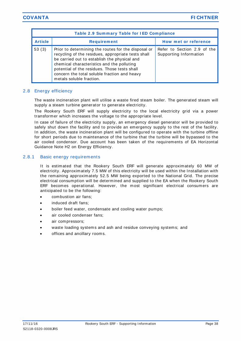
COVANTA FICHTNER
17/11/16 Rookery South ERF - Supporting Information Page 38
S2118-0320-0008JRS
Table 2.9 Summary Table for IED Compliance
Article Requirement How met or reference
53 (3) Prior to determining the routes for the disposal or
recycling of the residues, appropriate tests shall
be carried out to establish the physical and
chemical characteristics and the polluting
potential of the residues. Those tests shall
concern the total soluble fraction and heavy
metals soluble fraction.
Refer to Section 2.9 of the
Supporting Information
2.8 Energy efficiency
The waste incineration plant will utilise a waste fired steam boiler. The generated steam will
supply a steam turbine generator to generate electricity.
The Rookery South ERF will supply electricity to the local electricity grid via a power
transformer which increases the voltage to the appropriate level.
In case of failure of the electricity supply, an emergency diesel generator will be provided to
safely shut down the facility and to provide an emergency supply to the rest of the facility.
In addition, the waste incineration plant will be configured to operate with the turbine offline
for short periods due to maintenance of the turbine that the turbine will be bypassed to the
air cooled condensor. Due account has been taken of the requirements of EA Horizontal
Guidance Note H2 on Energy Efficiency.
2.8.1 Basic energy requirements
It is estimated that the Rookery South ERF will generate approximately 60 MW of
electricity. Approximately 7.5 MW of this electricity will be used within the Installation with
the remaining approximately 52.5 MW being exported to the National Grid. The precise
electrical consumption will be determined and supplied to the EA when the Rookery South
ERF becomes operational. However, the most significant electrical consumers are
anticipated to be the following:
combustion air fans;
induced draft fans;
boiler feed water, condensate and cooling water pumps;
air cooled condenser fans;
air compressors;
waste loading systems and ash and residue conveying systems; and
offices and ancillary rooms.

COVANTA FICHTNER
17/11/16 Rookery South ERF - Supporting Information Page 39
S2118-0320-0008JRS
An indicative Sankey Diagram for the waste incineration plant is presented in
Figure 3.
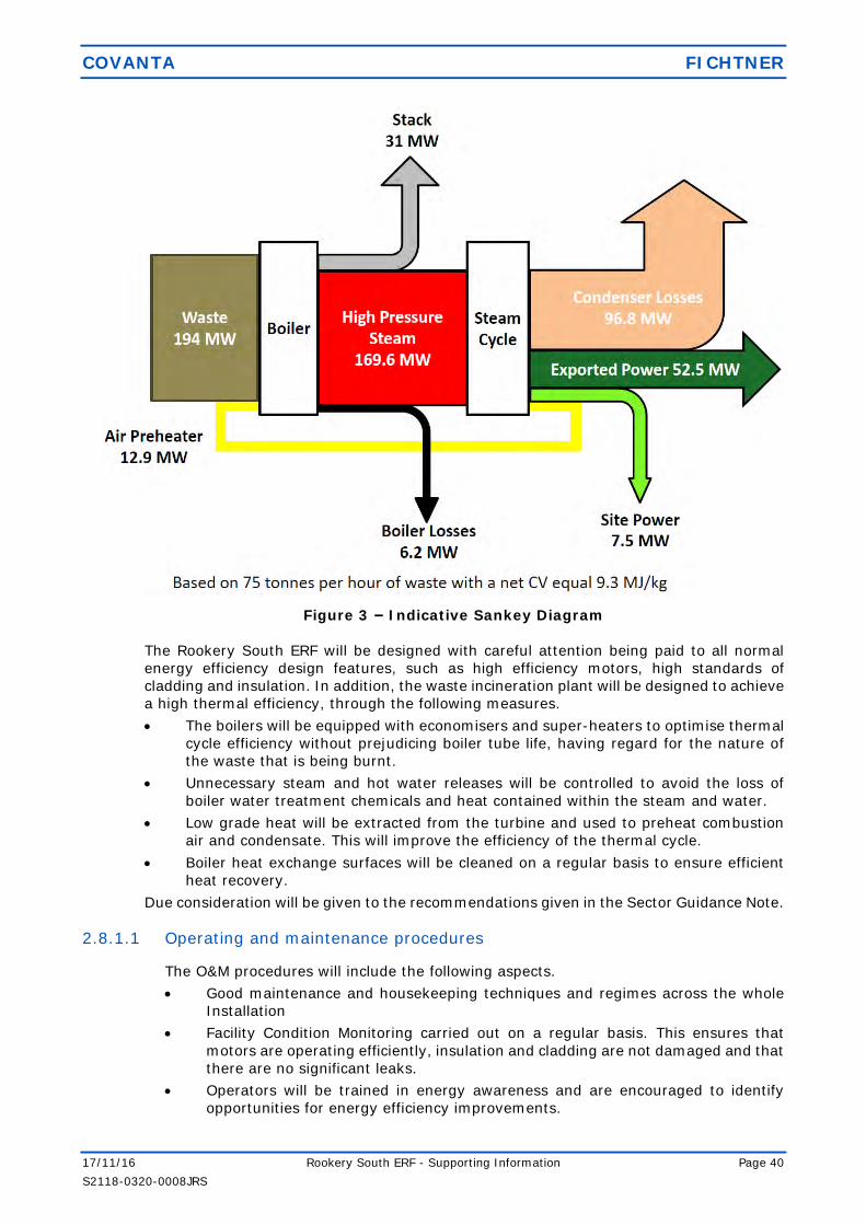
COVANTA FICHTNER
17/11/16 Rookery South ERF - Supporting Information Page 40
S2118-0320-0008JRS
Figure 3 – Indicative Sankey Diagram
The Rookery South ERF will be designed with careful attention being paid to all normal
energy efficiency design features, such as high efficiency motors, high standards of
cladding and insulation. In addition, the waste incineration plant will be designed to achieve
a high thermal efficiency, through the following measures.
The boilers will be equipped with economisers and super-heaters to optimise thermal
cycle efficiency without prejudicing boiler tube life, having regard for the nature of
the waste that is being burnt.
Unnecessary steam and hot water releases will be controlled to avoid the loss of
boiler water treatment chemicals and heat contained within the steam and water.
Low grade heat will be extracted from the turbine and used to preheat combustion
air and condensate. This will improve the efficiency of the thermal cycle.
Boiler heat exchange surfaces will be cleaned on a regular basis to ensure efficient
heat recovery.
Due consideration will be given to the recommendations given in the Sector Guidance Note.
2.8.1.1 Operating and maintenance procedures
The O&M procedures will include the following aspects.
Good maintenance and housekeeping techniques and regimes across the whole
Installation
Facility Condition Monitoring carried out on a regular basis. This ensures that
motors are operating efficiently, insulation and cladding are not damaged and that
there are no significant leaks.
Operators will be trained in energy awareness and are encouraged to identify
opportunities for energy efficiency improvements.

COVANTA FICHTNER
17/11/16 Rookery South ERF - Supporting Information Page 41
S2118-0320-0008JRS
2.8.1.2 Energy efficiency benchmarks
The Rookery South ERF will generate up to 60 MWe. As stated within the EA Guidance
Note – The Incineration of Waste (EPR5.01), the benchmark for the generation of
electricity from municipal waste incineration is 5-9 MW per 100,000 tonnes. Applying
the criteria stated within the EA guidance, the EfW will generate approximately
10.25 MW per 100,000 tonnes of waste. The efficiency of the Rookery South ERF
therefore is in accordance with the benchmark efficiency figure.
At the design point of 75 tph and a net calorific value of 9.3 MJ/kg, the waste
incineration plant will generate up to 60 MWe. Approximately 7.5 MWe of this electricity
will be used within the Rookery South ERF The remaining 52.5 MW will be exported to
the National Grid. This equates to 0.7 MWh/te waste, with 0.1 MWh/te waste used
within the facility, with 0.7 MWh/te waste exported to the grid. This is based on a design
waste Net Calorific Value of 2.83 MWh/te.
2.8.2 Further energy efficiency requirements
The Rookery South ERF will not be subject to a Climate Change Levy agreement, although
the electricity generated will be partially exempt from the levy.
In accordance with the requirements of the IED and the Energy Efficiency Directive, heat
should be recovered as far as practicable. A Heat Plan and CHP-R application for the facility
is presented in Annex 7.
2.9 Waste recovery and disposal
The main residue streams which will arise from the operation of the Rookery South ERF are:
(1) IBA from the combustion process (Residue Type RT1); and
(2) APCr and fine ash particles (Residue Type RT2).
Waste recovery and disposal techniques will be in accordance with the indicative BAT
requirements. The wastes generated are summarised in Table 2.11.
2.9.1 Metals separated from the received waste
Ferrous metals will be removed from the IBA by means of magnetic separators and
discharged to a separate storage area in the IBA processing facility. Any ferrous material
recovered will be recycled. Non-ferrous metals will be removed using an eddy current
separator.
2.9.2 Incinerator bottom ash (IBA)
As can be seen in the process flow diagram in Annex 1, boiler ash will be mixed with bottom
ash. The mixture of boiler ash and bottom ash is normally a non-hazardous waste which
can be recycled. If the boiler ash were to be mixed with the APC residues, the mixture
would be defined as hazardous waste and this would restrict the ability of the operator to
recycle the boiler ash.
IBA has been used for at least 20 years in Europe as a substitute for valuable primary
aggregate materials in the construction of roads and embankments. IBA processing will be
sited adjacent to the waste incineration plant. The process will produce secondary
aggregate of various grades for use in the construction industry. There will also be further
ferrous and non-ferrous metal extraction for recycling within this process.
The composition of the IBA is expected to be similar to that from other waste incineration
facilities in the UK. Table 2.10 shows the typical trace components found in IBA produced
in the UK.

COVANTA FICHTNER
17/11/16 Rookery South ERF - Supporting Information Page 42
S2118-0320-0008JRS
Table 2.10: Typical Composition of IBA
Component Unit Average Minimum Maximum
Total Organic Carbon % 1.4 0.00 3.2
Total cadmium mg/kg 12.1 0.00 190.0
Total mercury mg/kg 0.5 0.02 7.9
Total chromium mg/kg 145.1 0.00 580.0
Total copper mg/kg 1,356.6 4.00 5,700.0
Total lead mg/kg 1,306.2 0.00 6,800.0
Total nickel mg/kg 84.8 0.00 340.0
Thallium mg/kg 27.0 10.00 63.0
Managanese mg/kg 1,446.0 230.00 16,000.0
Arsenic mg/kg 11.7 2.00 45.0
Antimony mg/kg 81.2 0.00 760.0
Cobalt mg/kg 17.0 6.00 41.0
Vanadium mg/kg 45.1 10.00 120.0
Zinc mg/kg 2,688.5 3.60 13,000.0
Tin mg/kg 121.0 23.00 220.0
Dioxin/Furan (Total) ng/kg 529.9 0.00 2,500.0
Dioxin/Furan (ITEQ) ng/kg 9.4 0.00 55.0
2.9.3 Air pollution control residues
APCr are predominantly composed of calcium as hydroxide, carbonate, sulphate and
chloride/hydroxide complexes. Typical major element concentration ranges for the UK
residues are as follows:
30-36% w/w Calcium;
12-15% w/w Chlorine;
8-10% w/w Carbonate (as C); and
3-4% w/w Sulphate (as S).
Silicon, Aluminium, Iron, Magnesium and Fluorine are also present in addition to traces of
dioxins and the following heavy metals: Zinc, Lead, Manganese, Copper, Chromium,
Cadmium, Mercury, and Arsenic.
It may be possible to send the residue to an effluent treatment contractor, to be used to
neutralise acids and similar materials. Using the residues in this way avoids the use of
primary materials. If this option is not practicable then it will be sent to a secure landfill
for disposal as a hazardous waste.
APCr will be removed from site in enclosed tankers which will minimise the chance of
spillage and dust emissions. During the tanker filling operation, displaced air will vent back
to the silo and any releases to atmosphere would pass through a fabric filter.

COVANTA FICHTNER
17/11/16 Rookery South ERF - Supporting Information Page 43
S2118-0320-0008JRS
Table 2.11: Key Waste Streams
Source/
Material
Properties of
Waste
Storage
location/
volume
stored
Quantity of
waste
produced
(annual
estimate)
Disposal Route and
Transport Method
Frequency
IBA Grate ash, grate riddlings. This ash is relatively inert, classified as non-hazardous.
IBA storage bunker.
150,000 tonnes Sent to the IBA recycling facility adjacent to the ERF for further processing into a secondary aggregate, referred to as
Incinerator Bottom Ash Aggregate (IBAA). A small fraction may be
unsuitable for reuse and will be transferred off-site for disposal.
Transport occurs by road vehicles.
Daily
Fly Ash / APCr
Ash from boiler and dry flue gas treatment, may
contain some unreacted lime
APCr residue silos.
25,000 tonnes Recycled or disposed of in a licensed site for hazardous waste.
Transport occurs by road vehicle.
Daily
2.10 Management
The Facility will be designed and constructed following the latest international and national
regulations, standards and guidance. This will incorporate risk management techniques such
as HazOp studies prior to construction and thorough commissioning and testing before facility
takeover.
Covanta will ensure that continued Safety, Health and Environmental excellence will be
ensured by employing the latest management best practice as outlined below.
2.10.1 Management systems
As part of its ongoing commitment to sustainable and responsible development and to
regulatory compliance, Covanta has developed and implemented a documented EMS.
Measures are undertaken to ensure that this is communicated, understood and effectively
maintained throughout the organisation to meet the requirements of the BS EN ISO
14001:2004 Environmental Management System Standard.
Covanta will develop a management structure and a site specific EMS certified to ISO
14001. The EMS is part of the facility’s integrated management system that establishes an
organisational structure, responsibilities, practices, procedures and resources for
achieving, reviewing and maintaining the company’s commitment to environmental
protection. Covanta regards the ISO 14001 certification to be of considerable importance
and relevance to a waste treatment facility. It is an assurance to the local authority,
regulator, neighbours, and others alike that the facility operation is undertaken in strict
compliance with the regulations in force and with the management seeking continual
improvements. It requires the company to work in a transparent way, to maintain and
improve the confidence of regulators and neighbours, and to have a proactive approach to
environmental improvement.

COVANTA FICHTNER
17/11/16 Rookery South ERF - Supporting Information Page 44
S2118-0320-0008JRS
2.10.1.1 Scope and structure
The scope of Covanta’s current certification to ISO 14001 is for Covanta Energy’s current
operations. The scope will be extended to cover the operational Rookery Pit facility.
2.10.1.2 General Requirements
The EMS objectives and scope will ensure that the EMS includes the following
requirements:
(1) identifying potential environmental impacts;
(2) documenting and implementing standard procedures to mitigate and control these
impacts;
(3) determining a procedural hierarchy that considers the interaction of the relevant
processes;
(4) ensuring adequate responsibility, authority and resources to management
necessary to support the EMS;
(5) establishing performance indicators to measure the effectiveness of the
procedures;
(6) monitoring, measuring and analysing the procedures for effectiveness; and
(7) implementing actions as required based on the results of auditing to ensure
continual improvements of the processes.
2.10.1.3 Personnel
Sufficient numbers of staff, in various grades, will be required to manage, operate and
maintain the plant on a continuous basis, seven days per week throughout the year.
The plant will be managed, operated and maintained by experienced managers, boiler
operators and maintenance staff.
The key environmental management responsibilities will be allocated as described
below.
(1) The General Manager will have overall responsibility for management of the ERF
and compliance with the operating permit. The general manager will have
extensive experience relevant to his responsibilities.
(2) The Operations Managers will have day-to-day responsibility for the operation of
the plant, to ensure that the plant is operated in accordance with the permit and
that the environmental impact of the plant’s operations is minimised. In this
context, he or she will be responsible for designing and implementing operating
procedures which incorporate environmental aspects.
(3) The Maintenance Manager will be responsible for the management of maintenance
activities, for maintenance planning and for ensuring that the plant continues to
operate in accordance with its design.
2.10.1.4 Competence, Training and Awareness
Covanta aims to ensure that any persons performing tasks for it, or on its behalf, which
have the potential to cause significant environmental impact are competent on the basis
of appropriate education and training or experience.
Covanta’s EMS will contain a training procedure to make employees aware of:
(1) the importance of conformity with the environment policies and procedures and
with the requirements of the EMS;
(2) potentially significant environmental aspects associated with their work;
(3) their roles and responsibilities in achieving conformity with the requirements of
the EMS, including emergency preparedness and response requirements;

COVANTA FICHTNER
17/11/16 Rookery South ERF - Supporting Information Page 45
S2118-0320-0008JRS
(4) the relevance and importance of their activities and how they contribute to the
achievement of the environmental and quality objectives; and
(5) the potential consequences of the departure from specified procedures.
Covanta will comply with industry standards or codes of practice for training (e.g.
WAMITAB), where they exist. The EMS will contain an archiving procedure to ensure all
training is recorded and all associated records are retained.
2.10.1.5 Competence
Covanta will identify the minimum competencies required for each role. These will then
be applied to the recruitment process to ensure that key role responsibilities are
satisfied. Covanta will pay particular attention to potential candidate’s experience,
qualifications, knowledge and skills.
2.10.1.6 Induction and Awareness
Staff induction programmes are location and job role specific and will include, as a
minimum, the induction of:
(1) the Environmental Policy;
(2) the requirements of the Environmental Permit;
(3) the Health and Safety Policy and Procedures; and
(4) the EMS Awareness Training.
2.10.1.7 Training
Covanta will be required to train staff during commissioning of the Rookery South ERF
and before the plant is operational. Line Managers will be required to identify and
monitor staff training needs as part of the appraisal system.
Training records will be maintained onsite. Where applicable, will be required to comply
with industry standards or codes of practice for training (e.g. WAMITAB), where they
exist.
2.11 Closure
The planning permission for the Rookery South ERF has no finite date for the end of operations
or closure. During operations there will be a continuous programme of preventative and life
cycle maintenance that will ensure the replacement of key components at appropriate stages.
In this way, the plant will continue to operate to the same standards required by the
Environmental Permit for many years. When the ERF reaches the end of its operational life,
for whatever reason, and is proposed to be closed, it may be adapted for an alternative use,
or demolished as part of a redevelopment scheme and the site cleared and left in a fit-for-
use condition. These proposals would be subject to a new planning permission.
2.12 General
Covanta recognises the need to ensure that the design, the operation and the maintenance
procedures facilitate decommissioning in a safe manner without risk of pollution,
contamination or excessive disturbance to noise, dust, odour, ground and water courses.
To achieve this aim, a site closure plan will be prepared at the appropriate time. It is
anticipated that the closure plan will include the information listed below.
2.12.1 Site closure plan
The following is a summary of the measures to be considered within the closure plan to
ensure the safe and clean decommissioning of the facility.

COVANTA FICHTNER
17/11/16 Rookery South ERF - Supporting Information Page 46
S2118-0320-0008JRS
2.12.1.1 General requirements
Underground tanks and pipework to be avoided except for supply and discharge
utilities such as Towns Water, sewerage lines and grid connections.
Safe removal of all chemical and hazardous materials.
Adequate provision for drainage, vessel cleaning and dismantling of pipework.
Disassembly and containment procedures for insulation, materials handling
equipment, material extraction equipment, fabric filters and other filtration
equipment without significant leakage, spillage, dust or hazard.
The use of recyclable materials where possible.
Methodology for the removal/decommissioning of components and structures to
minimise the exposure of noise, disturbance, dust and odours and for the
protection of surface and groundwater.
Soil sampling and testing of sensitive areas to ensure the minimum disturbance
(sensitive areas to be selected with reference to the Site Condition Report).
2.12.1.2 Specific details
A list of recyclable materials/components and current potential outlet sources.
A list of materials/components not suitable for recycle and potential outlet
sources.
A list of materials to go to landfill with current recognised analysis, where
appropriate.
A list of all chemicals and hazardous materials, location and current containment
methods.
A Bill of Materials detailing total known quantities of items throughout the site
such as: steelwork; plastics; cables; concreate and civils materials; oils;
chemicals; consumables; contained water and effluents; and IBA and FGT
residues.
2.12.1.3 Disposal routes
Each of the items listed within the Bill of Materials will have a recognised or special route
for disposal; e.g. Landfill by a licensed contractor, disposal by high sided, fully sheeted
road vehicle or for sale to a recycling company, disposal by skip/fully enclosed container,
recycling company to collect and disposal by container.
2.13 Improvement programme
Covanta are committed to continual environmental improvement and are therefore
suggesting the following improvement conditions be incorporated into the Environmental
Permit.
2.13.1 Pre-Commissioning
Prior to the commencement of commissioning Covanta will:
(1) provide a written commissioning plan, including timelines for completion, for
approval by the EA. The commissioning plan will include the expected emissions to
the environment during the different stages of commissioning, the expected
durations of commissioning activities and the actions to be taken to protect the
environment and report to the EA in the event that actual emissions exceed expected
emissions. Commissioning will be carried out in accordance with the commissioning
plan as approved.

COVANTA FICHTNER
17/11/16 Rookery South ERF - Supporting Information Page 47
S2118-0320-0008JRS
(2) submit a written report to the EA detailing the waste acceptance procedure to be
used at the site. The waste acceptance procedure will include the process and
systems by which wastes unsuitable for incineration at the site will be controlled. The
procedure will be implemented in accordance with the written approval from the EA.
(3) provide a report with detailed plans to the EA for site infrastructure, including details
for underground structures and storage tanks.
(4) Submit a report which confirms to the EA, the NOx abatement techniques to be
employed within the final design of the Installation. The report will confirm whether
FGR has been included in the final design.
(5) The report will describe the performance of the Selective Non-Catalytic Reduction
(SNCR) system design and combustion settings to minimise oxides of nitrogen (NOx)
emissions within the IED emission limit values described in this permit with the
minimisation of nitrous oxide emissions. after completion of furnace design and
before any furnace operation, submit a written report to the EA of the details of the
computerised fluid dynamic (CFD) modelling. The report will demonstrate whether
the design combustion conditions comply with the residence time and temperature
requirements as defined by the Waste Incineration Directive.
(6) send a summary of the site Environment Management System (EMS) to the EA and
make available for inspection all documents and procedures which form part of the
EMS. The EMS will be developed in line with the requirements of “How to comply
with your Environmental Permit (EPR 1.00)‟, and will include a written accident
management plan, and site closure plan. The documents and procedures set out in
the EMS shall form the written management system referenced in condition 1.1.1
(a) of the permit.
(7) submit to the EA for approval a protocol for the sampling and testing of incinerator
bottom ash for the purposes of assessing its hazard status. Sampling and testing will
be carried out in accordance with the protocol as approved.
2.13.2 Post commissioning
Following the commissioning of the Rookery South ERF, Covanta will:
(1) within 12 months of the date on which waste is first burnt, submit a written report
to the EA on the implementation of the EMS and the progress made in the
accreditation of the system by an external body, or if appropriate submit a schedule
by which the EMS will be subject to accreditation.
(2) within 6 months of the completion of commissioning, submit a written proposal to
the EA to carry out tests to determine the size distribution of the particulate matter
in the exhaust gas emissions to air from emission points A1 to A3, identifying the
fractions within the PM10 and PM2.5 ranges. The proposal will include a timetable for
approval by the EA to carry out such tests and produce a report on the results. On
receipt of written agreement by the EA to the proposal and the timetable, Covanta
shall carry out the tests and submit to the EA a report on the results.
(3) within 4 months of the completion of commissioning, submit a written report to the
EA summarising the environmental performance of the ERF as installed against the
design parameters set out in the Application. The report shall also include a review
of the performance of the ERF against the conditions of the Environmental Permit
and details of procedures developed during commissioning for achieving and
demonstrating compliance with permit conditions.
(4) within 4 months of the completion of commissioning, carry out checks to verify the
residence time, minimum temperature and oxygen content of the exhaust gases in
the furnace whilst operating under the anticipated most unfavourable operating
conditions. The results will be submitted in writing to the EA.

COVANTA FICHTNER
17/11/16 Rookery South ERF - Supporting Information Page 48
S2118-0320-0008JRS
(5) within 4 months of the completion of commissioning, submit a written report to the
EA describing the performance of the Selective Non Catalytic Reduction (SNCR)
system and combustion settings to minimise oxides of nitrogen (NOx) emissions
within the emission limit values described in the Environmental Permit.
(6) within 15 months from commencement of operations, carry out an assessment of
the impact of emissions to air for the following component metals subject to emission
limit values: Cd, As, Cr(VI) and Ni. A report on the assessment will be submitted to
the EA. Emissions monitoring data obtained during the first year of operation will be
used to compare the actual emissions with those assumed in the impact assessment
submitted with the Application. An assessment shall be made of the impact of each
metal against the relevant EAL. In the event, the assessment shows that an EAL can
be exceeded, the report shall include proposals for further investigative work.
(7) submit a written summary report to the EA to confirm by the results of calibration
and verification testing that the performance of Continuous Emission Monitors for the
parameters specified in the Environmental Permit complies with the requirements of
BS EN 14181. The initial calibration report will be submitted to the EA within 3
months of completion of commissioning. The full summary evidence compliance
report will be submitted within 18 months of commissioning.
(8) undertake a noise assessment during normal operations to validate the assessment
provided within the Application. The assessment will be undertaken in accordance
with the procedures given in BS4142: 1997 (Rating industrial noise affecting mixed
residential and industrial areas) and BS7445: 2003 (Description and measurement
of environmental noise), or other methodology as agreed with the EA. The
assessment shall include, but not be limited to: a review of the noise sources from
the facility; a review of noise levels from static plant; and considerations of on-site
vehicle movements. A report shall be provided to the EA detailing the findings of the
assessment.

COVANTA FICHTNER
17/11/16 Rookery South ERF - Supporting Information Page 49
S2118-0320-0008JRS
Annex 1 – Plans and Drawings

COVANTA FICHTNER
17/11/16 Rookery South ERF - Supporting Information Page 50
S2118-0320-0008JRS
Annex 2 – Site Condition Report

COVANTA FICHTNER
17/11/16 Rookery South ERF - Supporting Information Page 51
S2118-0320-0008JRS
Annex 3 – Noise Assessment

COVANTA FICHTNER
17/11/16 Rookery South ERF - Supporting Information Page 52
S2118-0320-0008JRS
Annex 4 – Air Quality Assessment

COVANTA FICHTNER
17/11/16 Rookery South ERF - Supporting Information Page 53
S2118-0320-0008JRS
Annex 5 – BAT Assessment
COVANTA FICHTNER
17/11/16 Rookery South ERF - Supporting Information Page 54
S2118-0320-0008JRS
Annex 6 – Environmental Risk Assessment

COVANTA FICHTNER
17/11/16 Rookery South ERF - Supporting Information Page 55
S2118-0320-0008JRS
Annex 7 – Heat Study

COVANTA FICHTNER
17/11/16 Rookery South ERF - Supporting Information Page 56
S2118-0320-0008JRS
Annex 8 – Fire Prevention Plan

COVANTA FICHTNER
17/11/16 Rookery South ERF - Supporting Information Page 57
S2118-0320-0008JRS


