12
1 Cover for MMA™800T

1
Cover for MMA™800T
2
Intended to alert the user to the presence of uninsulated "dangerous voltage" within the product's enclosurethat may be of sufficient magnitude to constitute a risk of electric shock to persons.
Intended to alert the user of the presence of important operating and maintenance (servicing) instructions in the literature accompanying the product.
CAUTION: Risk of electrical shock – DO NOT OPEN!CAUTION: To reduce the risk of electric shock, do not remove cover. No user serviceable parts inside. Refer servicing to qualified service personnel.
WARNING: To prevent electrical shock or fire hazard, do not expose this appliance to rain or moisture. Before using this appliance, read the operating guide for further warnings.
Este símbolo tiene el propósito de alertar al usuario de la presencia de "(voltaje) peligroso" que no tiene aislamiento dentro de la caja del producto que puede tener una magnitud suficiente como para constituir riesgo de corrientazo.
Este símbolo tiene el propósito de alertar al usario de la presencia de instruccones importantes sobre la operación y mantenimiento en la literatura que viene con el producto.
PRECAUCION: Riesgo de corrientazo – No abra.PRECAUCION: Para disminuír el riesgo de corrientazo, no abra la cubierta. No hay piezas adentro que el usario pueda reparar. Deje todo mantenimiento a los técnicos calificados.
ADVERTENCIA: Para evitar corrientazos o peligro de incendio, no deje expuesto a la lluvia o humedad este aparato Antes de usar este aparato, lea más advertencias en la guía de operación.
Ce symbole est utilisé pur indiquer à l'utilisateur la présence à l'intérieur de ce produit de tension non-isolée dangereuse pouvant être d'intensité suffisante pour constituer un risque de choc électrique.
Ce symbole est utilisé pour indiquer à l'utilisateur qu'il ou qu'elle trouvera d'importantes instructions sur l'utilisation et l'entretien (service) de l'appareil dans la littérature accompagnant le produit.
ATTENTION: Risques de choc électrique – NE PAS OUVRIR!ATTENTION: Afin de réduire le risque de choc électrique, ne pas enlever le couvercle. Il ne se trouve à l'intérieur aucune pièce pouvant être réparée par l'utilisateur. Confier l'entretien à un personnel qualifié.
AVERTISSEMENT: Afin de prévenir les risques de décharge électrique ou de feu, n'exposez pas cet appareil à la pluie ou à l'humidité. Avant d'utiliser cet appareil, lisez les avertissements supplémentaires situés dans le guide.
Dieses Symbol soll den Anwender vor unisolierten gefährlichen Spannungen innerhalb des Gehäuses warnen, die von Ausreichender Stärke sind, um einen elektrischen Schlag verursachen zu können.
Dieses Symbol soll den Benutzer auf wichtige Instruktionen in der Bedienungsanleitung aufmerksam machen, die Handhabung und Wartung des Produkts betreffen.
VORSICHT: Risiko – Elektrischer Schlag! Nicht öffnen!VORSICHT: Um das Risiko eines elektrischen Schlages zu vermeiden, nicht die Abdeckung enfernen. Es befinden sich keine Teile darin, die vom Anwender repariert werden könnten. Reparaturen nur von qualifiziertem Fachpersonal durchführen lassen.
ACHTUNG: Um einen elektrischen Schlag oder Feuergefahr zu vermeiden, sollte dieses Gerät nicht dem Regen oder Feuchtigkeit ausgesetzt werden. Vor Inbetriebnahme unbedingt die Bedienungsanleitung lesen.
3
1
1
2 3 4
5 6 7 8 9 10
• 9 channel mixing system • Contour switch (special equalization)
• 20-20 kHz frequency response • Bass and treble controls
• Bridging input/output • Plug in module capability
• Dedicated program input • Rack-mountable or stand along package
GENERAL DESCRIPTIONThe Architectural Acoustics MMA™ 800T is a high quality mixer/preamp with nine input channels. Each
channel provides a level control, and the master output section features bass and treble EQ controls (defeatable),and special equalization contour.
The MMA™ 800T provides unmatched application flexibility with an array of optional plug-in modules,allowing each system to be tailor-made for specialized installations. Input modules may be loaded in, as required,for varying sound reinforcement applications, number of input channels, special functions, etc.
The program input includes a level control and is totally separate from the other eight channels. Externalsignals may be patched in at this point as a system auxiliary input or the ninth input channel. Signals appearing atthis input are routed directly to the master summing amplifier stage and are mixed with signals from the othereight channels. Systems requiring a single input may use the program input--making the purchase of an inputmodule unnecessary. The program level control regulates the level of this input and the signal is routed throughthe system bass and treble controls.
The MMA 800T is packaged as a stand-alone unit but will also rack-mount into a standard 19" rack withan optional rack-mount kit.
FRONT PANEL:
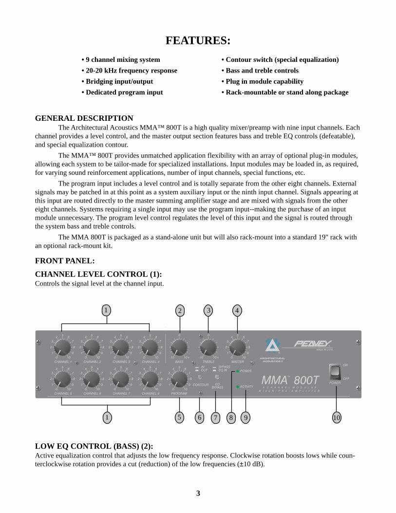
CHANNEL LEVEL CONTROL (1):Controls the signal level at the channel input.
FEATURES:
LOW EQ CONTROL (BASS) (2):Active equalization control that adjusts the low frequency response. Clockwise rotation boosts lows while coun-terclockwise rotation provides a cut (reduction) of the low frequencies (±10 dB).
4
HIGH EQ CONTROL (TREBLE) (3):Active equalization control that adjusts the high frequency response. Clockwise rotation boosts highs whilecounterclockwise rotation provides a cut (reduction) of the high frequencies (±10 dB).
MASTER (4):Controls the overall volume level of the system.
PROGRAM LEVEL CONTROL (5):Controls the signal level of the program input.
CONTOUR SWITCH (6):The "in" position of this switch provides a 6 dB boost at 100 Hz and 6 dB boost at 10 kHz. The "out" positionremoves boost from the system.
EQ BYPASS (7):The "in" position of this switch bypasses bass and treble equalization. The "out" position allows operation of theequalization.
POWER ON LED (8):Indicates when AC power is being supplied to the unit.
ACTIVITY LED (9):Indicates output level from the master mixing stage. The LED illuminates when signal level is approximately25 dB below rated output.
POWER SWITCH (10):Depress to "on" position to turn on.
REAR PANEL:
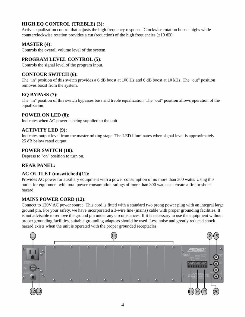
AC OUTLET (unswitched)(11):Provides AC power for auxiliary equipment with a power consumption of no more than 300 watts. Using thisoutlet for equipment with total power consumption ratings of more than 300 watts can create a fire or shockhazard.
MAINS POWER CORD (12):Connect to 120V AC power source. This cord is fitted with a standard two prong power plug with an integral largeground pin. For your safety, we have incorporated a 3-wire line (mains) cable with proper grounding facilities. Itis not advisable to remove the ground pin under any circumstances. If it is necessary to use the equipment withoutproper grounding facilities, suitable grounding adaptors should be used. Less noise and greatly reduced shockhazard exists when the unit is operated with the proper grounded receptacles.
11 14
16
18 19
15 17 2012 13
5
FUSE (13):WARNING: THE FUSE SHOULD ONLY BE REPLACED WHEN THE POWER CORDHAS BEEN DISCONNECTED FROM ITS POWER SOURCE.
The fuse is located within the cap of the fuseholder. If the fuse should fail, IT MUST BEREPLACED WITH THE SAME TYPE AND VALUE IN ORDER TO AVOID DAMAGE TOTHE EQUIPMENT AND TO PREVENT VOIDING THE WARRANTY. If the amp repeatedlyblows fuses, it should betaken to a qualified service center for repair.
MODULE INPUT PORTS (14):Accepts plug-in modules for all eight channels. Modules are optional and should be selected by installationrequirements. NOTE: All modules will function in any of the eight ports.
MUTE (15):Plug-in modules are available with muting function. The mute lines may be activated with an external switch atthis point.
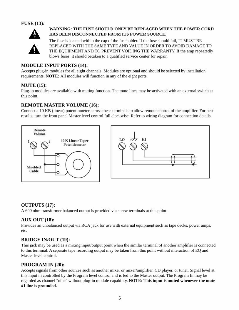
REMOTE MASTER VOLUME (16):Connect a 10 KB (linear) potentiometer across these terminals to allow remote control of the amplifier. For bestresults, turn the front panel Master level control full clockwise. Refer to wiring diagram for connection details.
OUTPUTS (17):A 600 ohm transformer balanced output is provided via screw terminals at this point.
AUX OUT (18):Provides an unbalanced output via RCA jack for use with external equipment such as tape decks, power amps,etc.
BRIDGE IN/OUT (19):This jack may be used as a mixing input/output point when the similar terminal of another amplifier is connectedto this terminal. A separate tape recording output may be taken from this point without interaction of EQ andMaster level control.
PROGRAM IN (20):Accepts signals from other sources such as another mixer or mixer/amplifier. CD player, or tuner. Signal level atthis input in controlled by the Program level control and is fed to the Master output. The Program In may beregarded as channel "nine" without plug-in module capability. NOTE: This input is muted whenever the mute#1 line is grounded.
RemoteVolume
10 K Linear TaperPotentiometer
ShieldedCable
21 HILO
6
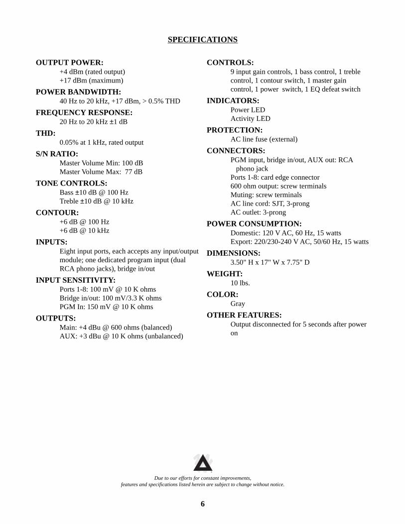
SPECIFICATIONS
OUTPUT POWER:+4 dBm (rated output)+17 dBm (maximum)
POWER BANDWIDTH:40 Hz to 20 kHz, +17 dBm, > 0.5% THD
FREQUENCY RESPONSE:20 Hz to 20 kHz ±1 dB
THD:0.05% at 1 kHz, rated output
S/N RATIO:Master Volume Min: 100 dBMaster Volume Max: 77 dB
TONE CONTROLS:Bass ±10 dB @ 100 HzTreble ±10 dB @ 10 kHz
CONTOUR:+6 dB @ 100 Hz+6 dB @ 10 kHz
INPUTS:Eight input ports, each accepts any input/outputmodule; one dedicated program input (dualRCA phono jacks), bridge in/out
INPUT SENSITIVITY:Ports 1-8: 100 mV @ 10 K ohmsBridge in/out: 100 mV/3.3 K ohmsPGM In: 150 mV @ 10 K ohms
OUTPUTS:Main: +4 dBu @ 600 ohms (balanced)AUX: +3 dBu @ 10 K ohms (unbalanced)
CONTROLS:9 input gain controls, 1 bass control, 1 treblecontrol, 1 contour switch, 1 master gaincontrol, 1 power switch, 1 EQ defeat switch
INDICATORS:Power LEDActivity LED
PROTECTION:AC line fuse (external)
CONNECTORS:PGM input, bridge in/out, AUX out: RCA phono jackPorts 1-8: card edge connector600 ohm output: screw terminalsMuting: screw terminalsAC line cord: SJT, 3-prongAC outlet: 3-prong
POWER CONSUMPTION:Domestic: 120 V AC, 60 Hz, 15 wattsExport: 220/230-240 V AC, 50/60 Hz, 15 watts
DIMENSIONS:3.50" H x 17" W x 7.75" D
WEIGHT:10 lbs.
COLOR:Gray
OTHER FEATURES:Output disconnected for 5 seconds after poweron
Due to our efforts for constant improvements,features and specifications listed herein are subject to change without notice.
TM®
7
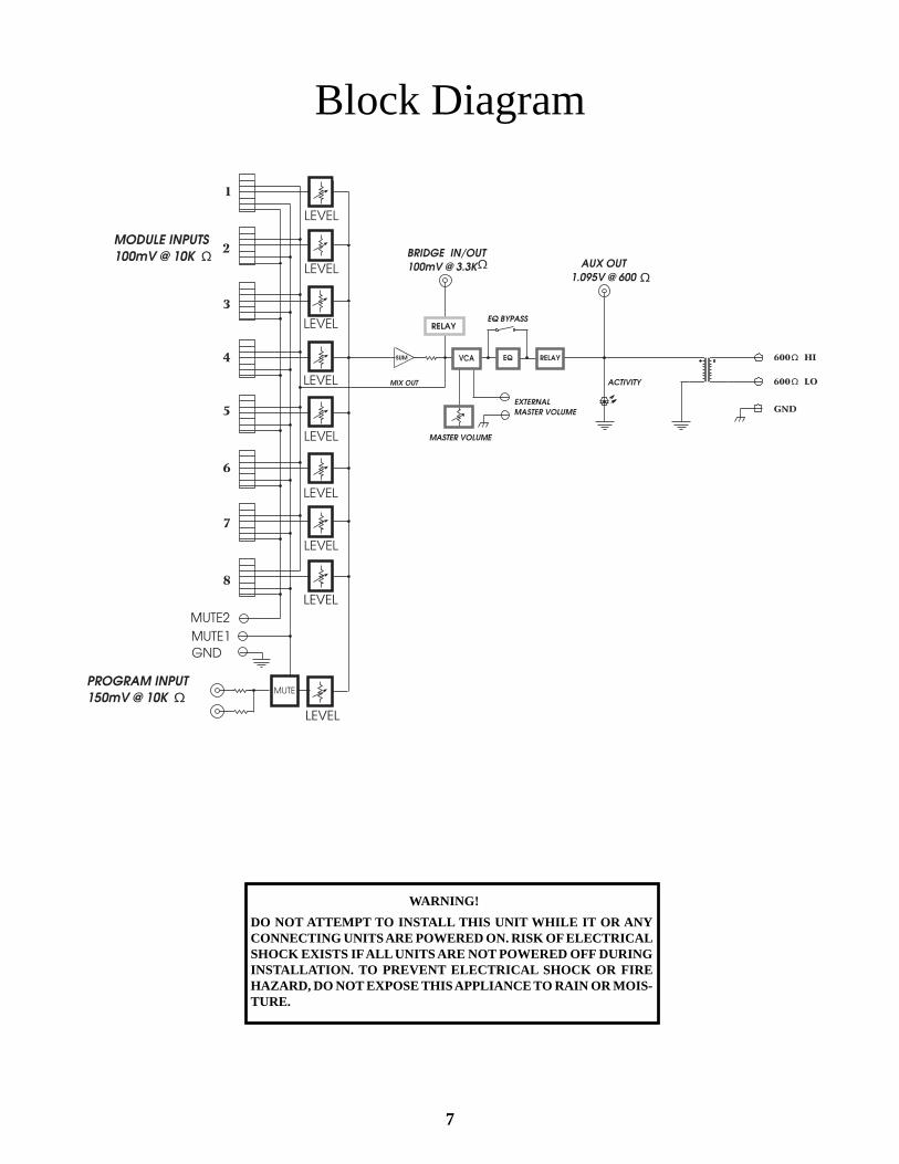
Block Diagram
WARNING!
DO NOT ATTEMPT TO INSTALL THIS UNIT WHILE IT OR ANYCONNECTING UNITS ARE POWERED ON. RISK OF ELECTRICALSHOCK EXISTS IF ALL UNITS ARE NOT POWERED OFF DURINGINSTALLATION. TO PREVENT ELECTRICAL SHOCK OR FIREHAZARD, DO NOT EXPOSE THIS APPLIANCE TO RAIN OR MOIS-TURE.

8

9
For further information on other Peavey ArchitecturalAcoustics products, ask your Authorized Peavey SoundContractor for the appropriate Peavey Architectural
Acoustics catalog/publication.The BluePrint
Commercial Sound For Permanent InstallationsEngineered Sound Products For Permanent Installations
Be sure to ask about products in the following categories:
Modular Series Mixer, Mixer/AmplifiersRack Kits for MA ™ Series Products
Wall Mount Mixer/AmplifiersNon-powered Mixers
Powered MixersEqualizers-Analog
Equalizers-ProgrammableElectronic Crossover/Delay Processors
Power AmplifiersLoudspeaker Systems
Acoustical ComponentsUtility Amplifiers, Mixer/AmplifiersRack Kits for UMA ™ Series Products
Telephone PagingZone Paging Systems
Mixers and Mixing ConsolesPower Amplifiers
Loudspeaker SystemsMicrophones
TM®
10
LIMITED WARRANTY
Peavey Electronics Corporation warrants to the original purchaser of this new Architectural Acousticsproduct that it is free from defects in material and workmanship. If within one (1) year from date of purchasea properly installed product proves to be defective and Peavey is notified, Peavey will repair or replace it atno charge. (Note: Batteries and patch cords not covered.) “Original purchaser” means the customer for whomthe product is originally installed. Damage resulting from improper installation, interconnection of a unit or system of another manufacturer,accident or unreasonable use, neglect or any other cause not arising from defects in material andworkmanship is not covered by this warranty. The warranty is valid only as to products purchased andinstalled in the United States and Canada. THIS LIMITED WARRANTY IS IN LIEU OF ANY AND ALL WARRANTIES, EXPRESSED OR IMPLIED,INCLUDING THE IMPLIED WARRANTIES OF MERCHANTABILITY AND FITNESS FOR A PARTICULAR USE.UNDER NO CIRCUMSTANCES WILL PEAVEY BE LIABLE FOR ANY LOST PROFITS, LOST SAVINGS,INCIDENTAL DAMAGES OR CONSEQUENTIAL DAMAGES ARISING OUT OF THE USE OR INABILITY TO USETHE PRODUCT, EVEN IF PEAVEY HAS BEEN ADVISED OF THE POSSIBILITY OF SUCH DAMAGE. THISLIMITED WARRANTY IS THE ONLY EXPRESSED WARRANTY ON THIS PRODUCT, AND NO OTHER STATE-MENT, REPRESENTATION, WARRANTY, OR AGREEMENT BY ANY PERSON SHALL BE VALID OR BINDINGUPON PEAVEY. Peavey’s liability to the original purchaser for damages for any cause whatsoever and regardless of theform of action is limited to the actual damages up to the greater of Five Hundred Dollars ($500) or an amountequal to the purchase price of the product that caused the damage or that is the subject of or is directly relatedto the cause of action. This limitation of liability will not apply to claims for personal injury or damage to realproperty or tangible personal property allegedly caused by Peavey’s negligence. For information on serviceunder this warranty, call a Peavey customer service representative at (601) 483-5376.
11
IMPORTANT SAFETY INSTRUCTIONSWARNING: When using electric products, basic cautions should always be followed, including the following.
1. Read all safety and operating instructions before using this product.
2. All safety and operating instructions should be retained for future reference.
3. Obey all cautions in the operating instructions and on the back of the unit.
4. All operating instructions should be followed.
5. This product should not be used near water, i.e., a bathtub, sink, swimming pool, wet basement, etc.
6. This product should be located so that its position does not interfere with its proper ventilation. It should not be placed flat against awall or placed in a built-in enclosure that will impede the flow of cooling air.
7. This product should not be placed near a source of heat such as a stove, radiator, or another heat producing amplifier.
8. Connect only to a power supply of the type marked on the unit adjacent to the power supply cord.
9. Never break off the ground pin on the power supply cord. For more information on grounding, write for our free booklet “ShockHazard and Grounding.”
10. Power supply cords should always be handled carefully. Never walk or place equipment on power supply cords. Periodically checkcords for cuts or signs of stress, especially at the plug and the point where the cord exits the unit.
11. The power supply cord should be unplugged when the unit is to be unused for long periods of time.
12. If this product is to be mounted in an equipment rack, rear support should be provided.
13. Metal parts can be cleaned with a damp rag. The vinyl covering used on some units can be cleaned with a damp rag or an ammonia-based household cleaner if necessary. Disconnect unit from power supply before cleaning.
14. Care should be taken so that objects do not fall and liquids are not spilled into the unit through the ventilation holes or any otheropenings.
15. This unit should be checked by a qualified service technician if:a. The power supply cord or plug has been damaged.b. Anything has fallen or been spilled into the unit.c. The unit does not operate correctly.d. The unit has been dropped or the enclosure damaged.
16. The user should not attempt to service this equipment. All service work should be done by a qualified service technician.
17. This product should be used only with a cart or stand that is recommended by Peavey Electronics.
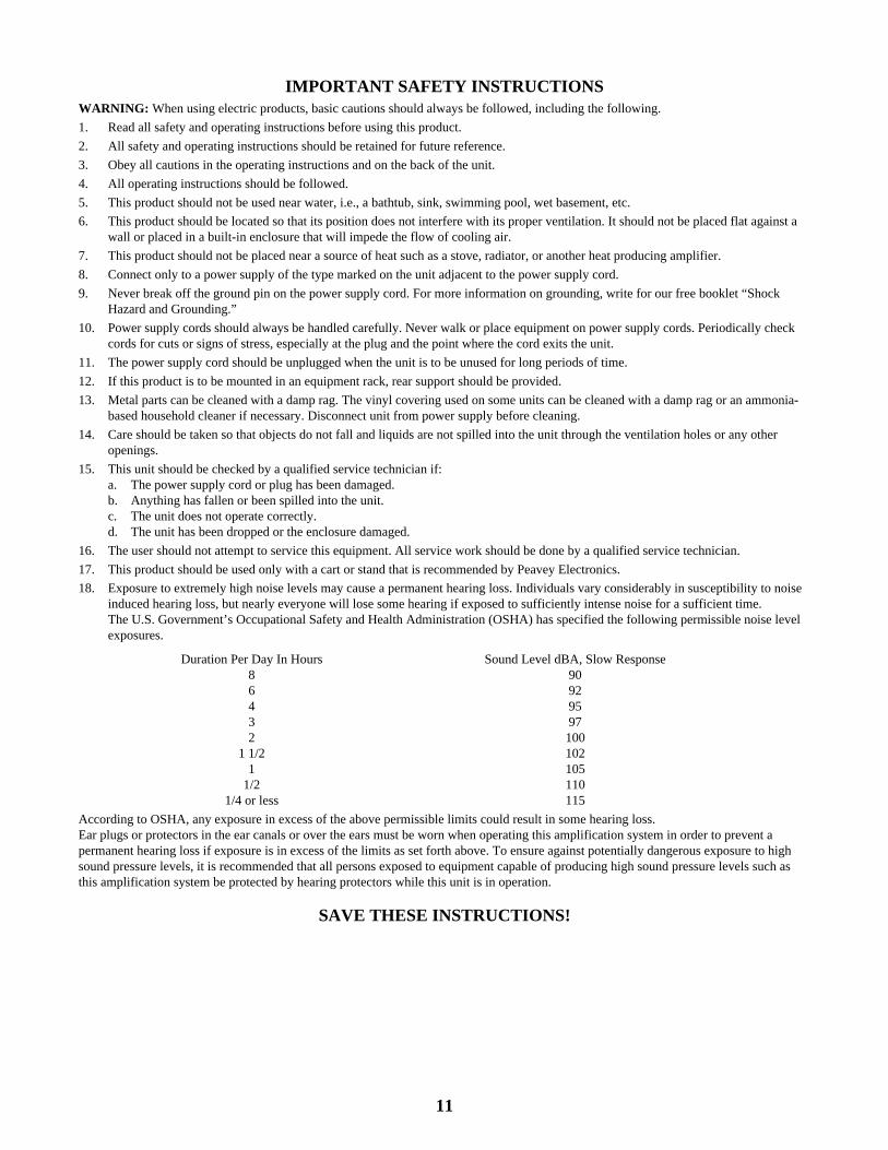
18. Exposure to extremely high noise levels may cause a permanent hearing loss. Individuals vary considerably in susceptibility to noiseinduced hearing loss, but nearly everyone will lose some hearing if exposed to sufficiently intense noise for a sufficient time.The U.S. Government’s Occupational Safety and Health Administration (OSHA) has specified the following permissible noise levelexposures.
Duration Per Day In Hours Sound Level dBA, Slow Response8 906 924 953 972 100
1 1/2 1021 105
1/2 1101/4 or less 115
According to OSHA, any exposure in excess of the above permissible limits could result in some hearing loss.Ear plugs or protectors in the ear canals or over the ears must be worn when operating this amplification system in order to prevent apermanent hearing loss if exposure is in excess of the limits as set forth above. To ensure against potentially dangerous exposure to highsound pressure levels, it is recommended that all persons exposed to equipment capable of producing high sound pressure levels such asthis amplification system be protected by hearing protectors while this unit is in operation.
SAVE THESE INSTRUCTIONS!

12
Features and specifications subject to change without notice.
Peavey Electronics Corporation 711 A Street / Meridian, MS 39301 / U.S.A. / (601) 483-5365 / Fax 486-1278©1995 #80302328 Printed in U.S.A. 12/95
®ARCHITECTURAL ACOUSTICS®
TM®


