14
Issued June 2010 13471 DATA SHEET 3VT1 MCCB ACCESSORIES Based on Siemens Catalog LV 36 – 2008

Issued June 2010 13471
DATA SHEET
3VT1 MCCB ACCESSORIES
Based on Siemens Catalog LV 36 – 2008

3VT1 Molded Case Circuit Breakers up to 160 AAccessories and Components
Auxiliary switches
■ Overview Auxiliary switches
Auxiliary and alarm switches
Function, name and location of switches according to type designation
1) In the accessory compartment 1, a 3VT9 100-2AB10 auxiliary switch and 3VT9 100-2AH10 signal switch cannot be used simultaneously.
2) When one of accessory compartments 4, 5 or 6 is already in use for auxil-iary switches, a shunt release or undervoltage release cannot be fitted additionally.
Location of switches in accessory compartments
Location of accessory compartments in a 3-pole 3VT1 circuit breaker/switch disconnector.
Location of accessory compartments in a 4-pole 3VT1 circuit breaker/switch disconnector.
When using one of the accessory compartments 4, 5 or 6, neither a shunt release nor an undervoltage release cannot be fitted.
Order No. Type Switch location Switch function
3VT9 100-2AB10 3VT9 100-2AB20
Auxiliaryswitch
Accessory compartment 11), 2, 3, 4, 5, 62)
Signaling of the state of the main contact of the circuit breaker/ switch dis-connector
3VT9 100-2AH10 3VT9 100-2AH20
Alarm switch
Accessory compartment 11)
Signal in the event of tripping of the cir-cuit breaker by the overcurrent release
13471
Based on Siemens Catalog LV 36 - 2008 Page 1 of 13
3VT1 Molded Case Circuit Breakers up to 160 AAccessories and Components
Auxiliary switches
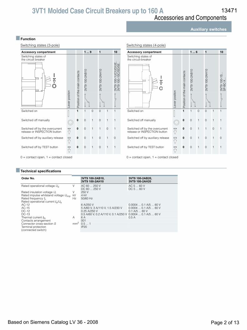
■ Function
Switching states (3-pole)
0 = contact open, 1 = contact closed
Switching states (4-pole)
0 = contact open, 1 = contact closed
■ Technical specifications
Accessory compartment 1 ... 9 1 10Switching states of the circuit breaker
Leve
r p
osito
n
Pos
ition
of t
he m
ain
cont
acts
3VT9
100
-2A
B10
3VT9
100
-2A
H10
3VT9
100
-1U
C/U
D/U
E..
3VT9
100
-1S
C/S
D/S
E..
Switched on 1 1 0 0 1 1
Switched off manually 0 0 1 0 1 1
Switched off by the overcurrent release or INSPECTION button
0 0 1 1 0 1
Switched off by auxiliary release 0 0 1 0 1 0
Switched off by TEST button 0 0 1 0 1 1
Accessory compartment 1 ... 6 1 10Switching states of the circuit-breaker
Leve
r p
osito
n
Pos
ition
of t
he m
ain
cont
acts
3VT9
100
-2A
B10
3VT9
100
-2A
H10
3VT9
100
-1S
...S
P-B
C-X
...
Switched on 1 1 0 0 1 1
Switched off manually 0 0 1 0 1 1
Switched off by the overcurrent release or INSPECTION button
0 0 1 1 0 1
Switched off by auxiliary release 0 0 1 0 1 0
Switched off by TEST button 0 0 1 0 1 1
Order No. 3VT9 100-2AB10, 3VT9 100-2AH10
3VT9 100-2AB20, 3VT9 100-2AH20
Rated operational voltage Ue V AC 60 ... 250 VDC 60 ... 250 V
AC 5 ... 60 V DC 5 ... 60 V
Rated insulation voltage Ui V 250 VRated impulse whitstand voltage Uimp kV 4 kVRated frequency fn Hz 50/60 HzRated operational current Ie/UeAC-12 6 A/250 V 0.0004 ... 0.1 A/5 ... 60 VAC-15 5 A/60 V, 3 A/110 V, 1.5 A/230 V 0.0004 ... 0.1 A/5 ... 60 VDC-12 0.25 A/250 V 0.1 A/5 ... 60 VDC-13 0.5 A/60 V, 0.2 A/110 V, 0.1 A/250 V 0.0004 ... 0.1 A/5 ... 60 VThermal current Ith A 6 A 0.5 AContacts arrangement 001Connector cross-section S mm2 0.5 ... 1 Terminal protection (connected switch)
IP20
13471
Based on Siemens Catalog LV 36 - 2008 Page 2 of 13

3VT1 Molded Case Circuit Breakers up to 160 AAccessories and Components
Auxiliary releases
■ Design
Auxiliary releases
Shunt release Undervoltage release
Location of auxiliary releases
Auxiliary releases in compartment 10
Type designation according to the rated operational voltage
Type designation according to the rated operational voltage
The specific rated operational voltage of the shunt release is set by jumpers directly on the release. The standard setting by the manufacturer is always to the value corresponding to the type designation.
Schematics
Shunt release Undervoltage release
■ Technical specifications
Ue Order No.AC/DC 24/48 V 3VT9 100-1SC00AC 110/230 V, DC 110/220 V 3VT9 100-1SD00AC 230/400 V, DC 220 V 3VT9 100-1SE00
Ue Order No.AC/DC 24/48 V 3VT9 100-1UC00AC 110/230 V /DC 110/220 V 3VT9 100-1UD00AC 230/400 V /DC 220 V 3VT9 100-1UE00
B1
U
B2
10.Y
2
N-
3VT9
100
-1S
.0
L+
NS
O0_
0005
5
10.Y
1 A1
U<
A2
10.Y
2
N-
3VT9
100
-1U
.0
L+
NS
O0_
0005
6
10.Y
1
Order No. 3VT9 100-1S.00Rated operational voltage Ue AC 24/48/110/230/400 V
DC 24/48/110/220 V Rated frequency fn 50/60 HzInput power at 1.1 Ue• AC 2 VA• DC 2 WCharacteristics U ≥ 0.7 Ue circuit breaker must tripTime before switching off 15 msLoading time ∞Connection cross-section S 0,5 ... 1 mm2
Terminal protection (connected release)
IP20
Location in accessory compartment no. 10
SIGNAL SWITCH - signals switching off by shunt trip
Rated operational voltage Ue AC 230 V Rated insulation voltage Ui 250 VRated impulse withstand voltage Uimp 4 kVRated frequency fn 50/60 HzRated operational current Ie/Ue 2 A/AC 230 V Thermal current Ith 6 AContact arrangement 01
Order No. 3VT9 100-1U.00Rated operational voltage Ue AC 24/48/110/230/400 V
DC 24/48/110/220 V Rated frequency fn 50/60 HzInput power at 1.1 Ue• AC 2 VA• DC 2 WCharacteristic U ≤ 0.35 Ue circuit breaker can be
switched on U ≥ 0.85 Ue circuit breaker must trip
Time before switching off 15 msLoading time ∞Connector cross-section S 0.5 ... 1 mm2
Terminal protection (connected release)
IP20
Location in accessory compartment no. 10
SIGNAL SWITCH - signals switching off of the undervoltage
Rated operational voltage Ue AC 230 V Rated insulation voltage Ui 250 VRated impulse withstand voltage Uimp 4 kVRated frequency fn 50/60 HzRated operational current Ie/Ue 2 A/AC 230 V Thermal current Ith 6 AContact arrangement 01
13471
Based on Siemens Catalog LV 36 - 2008 Page 3 of 13

3VT1 Molded Case Circuit Breakers up to 160 AAccessories and Components
Manual operating mechanisms
■ Design
Rotary operating mechanisms
The manual operating mechanism permits the actuating of the circuit breakers/switch disconnectors by turning the knob, e.g. in order to switch machines on and off. The modular concept of the operating mechanism allows for simple mounting on the cir-cuit breaker (even as an add-on). Mounting can be done after having removed the accessory compartment cover. An affixed drive may be sealed. The drive and its accessories are ordered separately according to your choice .The manual operating mechanism permits actuating the circuit breaker:a) from the front panel (Fig. 1)
3VT9 100-3HA/HB/HC/HD.. rotary operating unit + 3VT9 100-3HE/HF.. knob
b) through the control cabinet door (Fig.2)3VT9 100-3HA/HB/HC/HD.. rotary operating unit + 3VT9 100-3HJ.. extension shaft .. + 3VT9 100-3HG/HH.. coupling driver + 3VT9 100-3HE/HF.. knob
c) through the side wall of the control cabinet (Fig.3) in left- or right-side designs of manual operating mechanisms for lateral operation 3VT9 100-3HD10 (right) or 3VT9 100-3HC10 (left) + 3VT9 100-3HJ.. extension shaft + 3VT9 100-3HG/HH.. coupling driver + 3VT9 100-3HE/HF.. knob.• The manual operating mechanism is mounted directly on the
circuit breaker or switch disconnector.• The coupling driver is fixed to the control cabinet door and
provides for degree of protection IP40 or IP66. • The knob is mounted onto the manual operating mechanism
or onto the coupling driver.• The extension shaft is supplied in two versions, standard
(length 350 mm - can be shortened) and telescopic (adjust-able length 199 ... 352 mm). It is fitted onto the manual oper-ating unit.
Enhanced safety for operator• The manual operating unit and knob are also supplied with the
option to lock the circuit breaker into the “switched off manu-ally” position. The manual operating unit and lever can be locked with up to three padlocks with a shaft diameter up to 3 ... 4 mm.
• Every coupling driver prevents the control cabinet door from opening when the circuit breaker is switched on or in a state of being switched off by releases. By means of this device, it is possible to switch off this locking and to open the door. Locking of the control cabinet door is also possible in the „switched off manually“state of the circuit breaker. It is neces-sary to activate the locking by means of the knob on the cou-pling drive and to lock the hand drive arm.
• Two circuit breakers with manual operating mechanism can also be provided with reciprocal mechanical interlocking or mechanical parallel switching (see page ).
Features
Order No. Description Color Locking while the circuit breaker is in switched off state
Degree of Protection
Switchgear door locking in circuit breaker state
Length mm
switched on switched off manually and locked
3VT9 100-3HA10 Rotary operating mechanism gray no -- -- -- --3VT9 100-3HA20 gray yes -- -- -- --3VT9 100-3HB20 yellow yes -- -- -- --
3VT9 100-3HC10 Rotary operating mechanism - lateral, left
grey no -- - -- --
3VT9 100-3HD10 Rotary operating mechanism - lateral, right
grey no -- - -- --
3VT9 100-3HE10 Knob black no -- -- -- --3VT9 100-3HE20 black yes -- -- -- --3VT9 100-3HF20 red yes -- -- -- --
3VT9 100-3HG10 Coupling driver black -- IP40 yes yes --3VT9 100-3HH10 black -- IP40 yes yes --3VT9 100-3HG20 yellow -- IP66 yes yes --3VT9 100-3HH20 yellow -- IP66 yes yes --
3VT9 100-3HJ10 Extension shaft -- -- -- -- -- 350 (can be shorted)3VT9 100-3HJ20 -- -- -- -- -- 199 ... 352 telescopic
13471
Based on Siemens Catalog LV 36 - 2008 Page 4 of 13
5

3VT1 Molded Case Circuit Breakers up to 160 AAccessories and Components
Manual operating mechanismsMechanical interlocks and mechanical interlocks for parallel switching
3VT9 100-8LA00 mechanical interlocking
The mechanical interlocks are for the mechanical interlocking of two circuit breakers so that they cannot be tripped simulta-neously, but always just individually. Both circuit breakers may be switched off simultaneously. Interlocking can be used be-tween two 3VT1 circuit breakers. Each circuit breaker must be furnished with a manual operating mechanism – at least one with a manual operaitng unit and a knob, (see page ) . In order to use the interlocking, it is absolutely necessary to comply with the dimensions shown in the figure and given in the table.
Arrangement of circuit breakers/switch disconnectors with 3VT9 100-8LA00 mechanical interlocks
3VT9 100-8LB00 mechanical interlocks for parallel switching
Mechanical interlocks for parallel switching are for simultaneous switching of two circuit breakers. Parallel switching can be used between two 3VT1 circuit breakers. Each circuit breaker must be furnished with a manual operating unit and at least one with a knob ( see page ) . In order to use parallel switching, it is ab-solutely necessary to comply with the dimensions shown in the figure and given in the table.
Arrangement of circuit breakers/switch disconnectors with 3VT9 100-8LB00 mechanical interlocks for parallel switching
Dimensions mmX 87.5 or 100L 94.5 or 106
NS
O0_
0005
7
L
X
NS
O0_
0005
9
12.5 or 25
Dimensions mmX 75 or 87.5 or 100L L
NS
O0_
0005
8
X
L
NS
O0_
0006
0
0 or 12.5 or 25
13471
Based on Siemens Catalog LV 36 - 2008 Page 5 of 13
4
4

3VT1 Molded Case Circuit Breakers up to 160 AAccessories and Components
Motorized operating mechanisms
■ Design
Motorized operating mechanisms The motorized operating mechanism is an accessory of the cir-cuit breaker/switch disconnector, by means of which it is possi-ble to switch the circuit breaker or switch disconnector remotely on and off. The modular design of the operating mechanism en-ables its simple mounting on the circuit breaker (also addition-aly). The operating mechanism is used for both remote and local control of 3VT1 3-pole and 4-pole circuit breakers. It is manufac-tured in the version for lateral mounting next to the circuit breaker on the switchboard or for mounting on standard mounting rails. The operating mechanism is fastened by means of a bayonet mechanism on the circuit breaker side. The installed operating mechanism can be sealed by means of the terminal cover seal.3VT1 circuit breakers Modeion with motorized operating mech-anism are intended for industrial, power engineering and infra-structure applications. The motorized operating mechanisms are for direct actuation of the circuit breaker, without a spring storage unit.The motorized operating mechanism can work in the local or re-mote control mode. The local control mode is used, for instance, in case of loss of the control voltage. Local control of the circuit breaker is only accessible after lifting the transparent safety cover off the operating mechanism. This procedure locks the re-mote electrical control circuits automatically. The lifted position of the cover can be indicated remotely.The circuit breaker is switched on and off by means of the control lever driver. After returning the safety cover to the original position, the operating mechanism is switched automatically into the remote control mode.After having taken off the safety cover, it is possible to actuate anautomatic mode selector switch. Under the transparent cover, there is a red LED. The lighting of the LED indicates a failure (failed on/off/wind-up operations).Electronic circuits of the motorized operating mechanism block erroneous control process, e.g. drive cycling after overcurrent or auxiliary release tripping.Lateral operating mechanisms can be locked in „off position“ of the circuit breaker by up to three padlocks with a shank diameter of max. 4 mm. It is possible to actuate the locking remotely. The protective cover of the operating mechanisms can also be sealed.Motorized operating mechanism automatic operation presetsThe position of the main circuit breaker is indicated by the position of the circuit breaker driver lever under the transparent protective cover of the operating mechanism. The wound up po-sition of the circuit breaker can also be signalled remotely.In the remote control mode, the circuit breaker is switched on and off by an ON and OFF pushbutton. The accessories for the
motorized operating mechanism includes an 3VT9 100-3MF00 extension cable .
1) Standard factory setting of the switch.2) When the circuit breaker is switched off by the motorized operating mech-
anism electrically with the use of the OFF push button, the circuit breaker control lever gets into the wound up position automatically, indepen-dently of the automatic operation preset.
3) By pressing the OFF pushbutton, the motorized operaitng mechanism only winds the circuit breaker up to the position .
Symbol Description
Switched on maually or by motorized operating mecha-nism electrically
Switched off by overcurrent releases, shunt release or undervoltage release, TEST or REVISION pushbutton
Switched off maually or by motorized operating mecha-nism electrically, wound up state
Switch position
Automatic operation preset
Preset description
Circuit breaker switching off to postion2)
Circuit breaker winding up to position
Circuit breaker switching on to position
11) Automatic winding up is on
By overcurrent release
By REVISION pushbutton
By auxiliary release
By TEST pushbutton
The motorized operating mechanism carries outautomatically
By pressing the ON pushbutton
2 Automatic winding up is off
The operator must press the OFF pushbutton
By pressing the ON push button
3 Simultaeous winding up and switching on
By pressing the ON pushbutton, the motorized operating mech-anism will wind up and switch on the circuit breaker3)
The motorized operating mechanism is out of operation, the red LED is lighting.
N0
1 2
N0
1 2
N0
1 2
N0
1 2
13471
Based on Siemens Catalog LV 36 - 2008 Page 6 of 13

3VT1 Molded Case Circuit Breakers up to 160 AAccessories and Components
Motorized operating mechanisms
■ Schematics
For a complete schematic of the 3VT1 circuit breaker with motorized operating mechanism, see page .
Technical specifications
1) The values depend on the motorized operating mechanism automatic operation preset, see pages 21, 23, 24, 25.
Explanation of designations
1) Voltage on terminals 5, 6, 7, 8 is the same as Un of the motorized operating mechanism.
Order No. 3VT9 100-3M.00
Rated operational voltage Ue AC 24/48/110/230 VDC 24/48/110/220 V
Rated frequency fn 50/60 Hz
Control pulse lengthfor switching onfor switching off
60 ms ... ∞1)
60 ms ... ∞1)
Time for switching on < 70 ms1)
Time for switching off < 50 ms1)
Frequency of cycles ON/OFF 5 cycles/min
Frequency of cycles-successive ON/OFF 10 cycles
Mechanical endurance 20000 cycles
Power input AC 100 VA
DC 100 W
Starting current 12 A/AC/DC 24 V 6 A/AC/DC 48 V4 A/AC/DC 110 V2 A/AC 230 V/DC 220 V
Protection AC 24/48/110 V; AC 230 VDC 24/48/110 V; DC 220 V
LSN 4C/1; LSN 2C/1LSN-DC 4C/1; LSN-DC 2C/1
Order No. 3VT9 100-3MF00
Number of conductors 8
Conductor cross section S 0.35 mm2
Conductor length 60 cm
L+Q3
X3
MP
X3 2
4
5
3
6
1
7 8
M
NS
O0_
0006
1
B
P
HL1 HL2 HL3 HL4
B
N-
MP control circuit
ONOFF
Motor drive
MP control circuit, signalling
MP 3VT9 100-3M.00 motorized oeprating mecha-nism
M motor
P gearbox
X3 connector for connection of control and signal-ing circuits
B recommended connection of control circuits- not part of MP
ON pushbutton
OFF pushbutton
Q3 motorized operating mechanism circuit breaker
HL1 remote failure signalling (unreliable making or breaking), permissible load max. 10 W1)
HL2 signalling of circuit breaker lever „wound up“ position, permissible load max. 10 W1)
HL3 signalling of opening of the front safety cover of the operating mechanism, permissible load max. 10 W1)
HL4 signalling of extension of the operating mecha-nism locking bar, permissible load max. 10 W1)
13471
Based on Siemens Catalog LV 36 - 2008 Page 7 of 13
..

3VT1 Molded Case Circuit Breakers up to 160 AAccessories and Components
Motorized operating mechanisms3VT1 circuit breakers with motorized operating mechanism
Electrical switching off of the circuit breaker by motorized oper-ating mechanism (OFF pushbutton)Automatic operation no. 1, 2, 3
Electrical switching on of the circuit breaker by motorized oper-ating mechanism (ON pushbutton).
Automatic operation no. 1, 2, 3
Recommended control pulses for electrically switching on and off the circuit breaker using the ON and OFF pushbuttons
Automatic operation no. 1
Automatic operation no. 2
Automatic operation no. 3
Graph description
01
01
01
t [ms]
55
NS
O0_
0006
2
50
50
Auxiliary switch - NC contact
Auxiliary switch - NO contact
Main contacts
01
01
01
t [ms]
65
70
70
NS
O0_
0006
3
Auxiliary switch - NC contact
Auxiliary switch - NO contact
Main contacts
NS
O0_
0006
4
t [ms]
10
10
10
HK
NS
60 … 500
50
60 … 500>20> 520 > 520
> 20
< 70
IMP OFF IMP ON
NS
O0_
0006
5
t [ms]
10
10
10
HK
NS
60 … ∞
50
60 … ∞>20> 520 > 520
> 20
< 70
IMP OFF IMP ON
NS
O0_
0006
6
t [ms]
10
10
10
HK
NS
60 … 500
50
60 … 500> 20> 520 > 520
> 20
< 70
IMP ONIMP OFF
Symbol Description
HK Main contacts
NS Signal switch
IMP ON Make pulse for motorized operating mechanism
IMP OFF Break pulse for motorized operating mechanism
Switched on
Switched off maually or electrically by motorized operat-ing mechanism (wound up state)
13471
Based on Siemens Catalog LV 36 - 2008 Page 8 of 13

3VT1 Molded Case Circuit Breakers up to 160 AAccessories and Components
Motorized operating mechanismsCircuit breaker switching off by overcurrent release or INSPECTION pushbutton
Automatic operation no. 1
Automatic operation no. 2
Automatic operation no. 3
10
10
10
15
5
01
01
01
01
01
1085
1080
NS
O0_
0006
7
t [ms]
246
135
3.4 3.3
3.2 3.1
2.4 2.3
2.2 2.1
Main contacts
Auxiliary switch - NO contact
Auxiliary switch - NC contact
Signal switch - NO contact
Signal switch - NC contact
acce
ssor
yco
mpa
rtm
ent
3
acce
ssor
yco
mpa
rtm
ent
2
10
10
10
15
5
01
01
01
01
01 N
SO
0_00
068
t [ms]
246
135
3.4 3.3
3.2 3.1
2.4 2.3
2.2 2.1
Main contacts
Auxiliary switch - NO contact
Auxiliary switch - NC contact
Signal switch - No contact
Signal switch - NC contact
acce
ssor
yco
mpa
rtm
ent
3
acce
ssor
yco
mpa
rtm
ent
2
10
10
10
15
5
01
01
01
01
01 N
SO
0_00
068
t [ms]
246
135
3.4 3.3
3.2 3.1
2.4 2.3
2.2 2.1
Main contacts
Auxiliary switch - NO contact
Auxiliary switch - NC contact
Signal switch - No contact
Signal switch - NC contact
acce
ssor
yco
mpa
rtm
ent
3
acce
ssor
yco
mpa
rtm
ent
2
13471
Based on Siemens Catalog LV 36 - 2008 Page 9 of 13

3VT1 Molded Case Circuit Breakers up to 160 AAccessories and Components
Motorized operating mechanismsRecommended control pulses for switching the circuit breaker with motorized operating mechanism after its switching off by overcurrent release or INSPECTION pushbutton
Automatic operation no. 1
Automatic operation no. 2
Automatic operation no. 3
* If the circuit breaker was switched off by an overcurrent release, it is nec-essary to remove the error before its switching on.
Graph description
Symbol Description
HK Main contacts
NS Signal switch
IMP ON Make pulse for motorized operating mechanism
IMP OFF Break pulse for motorized operating mechanism
Switched on
Switched off by releases, TEST or INSPECTION pushbut-ton
Switched off maually or electrically by motorized operat-ing mechanism (wound up state)
10
10
10
1070
70
NS
O0_
0006
9
t [ms]
HK
NS
60 … 500> 15001)
IMP ON
60 … ∞10
10
10
70
70
NS
O0_
0007
0
t [ms]
HK
NS
60 … ∞
1)
> 500> 20
IMP OFF IMP ON
10
10
10
70
140
60 … 500
NS
O0_
0007
1
t [ms]
HK
NS
1)
IMP ON
13471
Based on Siemens Catalog LV 36 - 2008 Page 10 of 13
3VT1 Molded Case Circuit Breakers up to 160 AAccessories and Components
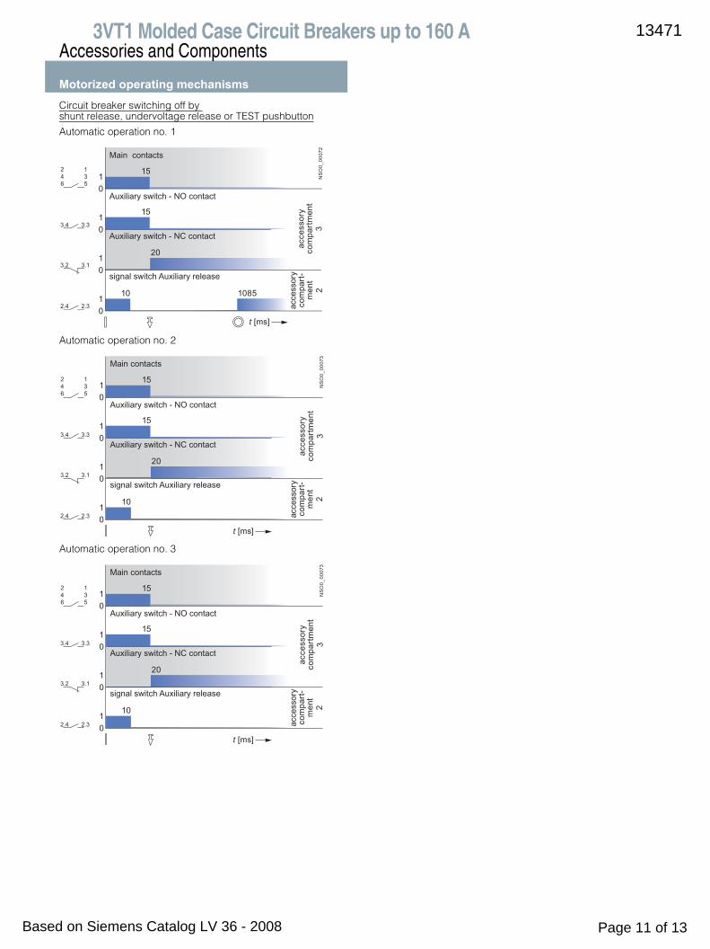
Motorized operating mechanismsCircuit breaker switching off by shunt release, undervoltage release or TEST pushbutton
Automatic operation no. 1
Automatic operation no. 2
Automatic operation no. 3
15
15
20
10
01
01
01
01
t [ms]
1085
NS
O0_
0007
2
246
135
3.4 3.3
3.2 3.1
2.4 2.3ac
cess
ory
com
part
men
t3
acce
ssor
yco
mpa
rt-
men
t2
Main contacts
Auxiliary switch - NO contact
Auxiliary switch - NC contact
signal switch Auxiliary release
15
15
20
10
01
01
01
01
t [ms]
NS
O0_
0007
3
246
135
3.4 3.3
3.2 3.1
2.4 2.3
Main contacts
Auxiliary switch - NO contact
Auxiliary switch - NC contact
signal switch Auxiliary release
acce
ssor
yco
mpa
rtm
ent
3
acce
ssor
yco
mpa
rt-
men
t2
15
15
20
10
01
01
01
01
t [ms]
NS
O0_
0007
3
246
135
3.4 3.3
3.2 3.1
2.4 2.3
Main contacts
Auxiliary switch - NO contact
Auxiliary switch - NC contact
signal switch Auxiliary release
acce
ssor
yco
mpa
rtm
ent
3
acce
ssor
yco
mpa
rt-
men
t2
13471
Based on Siemens Catalog LV 36 - 2008 Page 11 of 13

3VT1 Molded Case Circuit Breakers up to 160 AAccessories and Components
Motorized operating mechanismsRecommended control pulses for switching the circuit breaker with motorized operating mechanism after its switching off by overcurrent release or INSPECTION pushbutton
Automatic operation no. 1
Automatic operation no.2
Automatic operation no. 3
* Reswitching is only possible after deactivation of the shunt trip or under-voltage release.
Graph description
15 1070
01
01
01
01
01
t [ms]
NS
O0_
0007
4HK
SP
SV
NS
70
60 … 500
> 2001)
> 2001)
> 1500
IMP ON
1570
01
01
01
01
01
t [ms]
NS
O0_
0007
5
HK
SP
SV
NS
70
60 … ∞60 … ∞
> 2001)
> 2001)
> 20> 500
IMP ONIMP OFF
15
01
01
01
01
01 N
SO
0_00
076
t [ms]
HK
SP
SV
NS
70
60 … 500
> 2001) 140
> 2001)
> 500
IMP ON
Symbol Description
HK Main contacts
NS Signal switch
SV Pulse for shunt trip
SP Pulse for undervoltage release
IMP ON Make pulse for motorized operating mechanism
IMP OFF Break pulse for motorized operating mechanism
Switched on
Switched off by releases, TEST or REVISION pushbutton
Switched off maually or by electrically by motorized oper-ating mechanism (wound up state)
13471
Based on Siemens Catalog LV 36 - 2008 Page 12 of 13

3VT1 Molded Case Circuit Breakers up to 160 AAccessories and Components
Motorized operating mechanismsOvercurrent releases Tripping characteristics: class MThe tripping time of the overcurrent release of 3VT1 circuit break-ers with characteristic M at 7.2 In corresponds to the release class 10, 10 and 20 according to EN 60947-4-1.
Plate of the overcurrent releases with characteristic M
Rated short-circuit ultimate and service breaking capacity of 3-pole 3VT1 circuit breakers in DC circuitsSpecifications
1) in reverse connection of the circuit breaker (input terminals 2, 4, 6 and out-put terminals 1, 3, 5), Icu does not change.
Circuit breaker connection for circuits DC 250 V
Delay device
• The delay can be set at three levels (depending on connec-tion)
• The 3VT9 00-1UX00 unit is inteded only for undervoltagereleases with Ue = AC 230 V
Rated current In
Order No. Class
16 3VT1 701-2DM36-0AA0 10A20 3VT1 702-2DM36-0AA0 10A25 3VT1 792-2DM36-0AA0 10A
32 3VT1 703-2DM36-0AA0 1040 3VT1 704-2DM36-0AA0 1050 3VT1 705-2DM36-0AA0 20
63 3VT1 706-2DM36-0AA0 2080 3VT1 708-2DM36-0AA0 20100 3VT1 710-2DM36-0AA0 20
Order No. 3VT1 7..-2DM36-0AA0
Rated operational voltage Ue DC 250 V
Rated ultimate short-circuit breaking capacity1) (rms value)Icu/Ue
25 kA/DC 250 V; τ = max. 5 ms
Rated service short-circuit breaking capacity (rms value) Ics/Ue
13 kA/DC 250 V; τ = max. 5 ms
Utilization category (switching mode) DC-22A
Order No. Description Packing pc
3VT9 00-1UX00 Enables delayed tripping of undervoltage releases of 3VT circuit breakers
1
Circuit breakers Delay
1st level 2nd level 3rd level
s s s
3VT1 1 2 3.2
3VT2, 3VT3 0.6 1.2 1.9
3VT4, 3VT5 0.5 1 1.5
3VT13VT2,3VT33VT4/5
1 s0,6 s0,5 s
1 3 5
U<
2+ 4 6 8Ue
3VT13VT2,3VT3 3VT4/5
2 s1,2 s1 s
1 3 5
U<
2+ 4 6 8Ue
3VT13VT2,3VT33VT4/5
3,2 s1,9 s1,5 s
1 3 5
U<
2+ 4 6 8Ue
NS
O0_
0007
7
STOP STOP STOP
13471
Based on Siemens Catalog LV 36 - 2008 Page 13 of 13
![Accessories - elprom-rit.comelprom-rit.com/.../hyundai/avtomat_l_vol/mccb/data/Accessories.pdf · 192 Accessories U-Series /Molded Case Circuit Breaker Trip alarm switch [ ALT ] Surface](https://static.documents.pub/doc/80x56/5ba6995709d3f22c448c075d/accessories-elprom-ritcomelprom-ritcomhyundaiavtomatlvolmccbdata.jpg)


