67
CP-008872 Garneau Housing Development Preliminary Geotechnical Investigation – Final City of Edmonton Project number: 60655308 (501) C-Release No: 4000107835 May 05, 2021
CP-008872 Garneau Housing Development Preliminary Geotechnical Investigation – Final
City of Edmonton
Project number: 60655308 (501) C-Release No: 4000107835 May 05, 2021

Garneau Housing Development Preliminary Geotechnical Investigation
Project number: 008872/60655308
RPT-2021-05-05 C of Edm-CP-008872 Garneau Housing Prelim Geotech Investigation-60655308.docx
Statement of Qualifications and Limitations
The attached Report (the “Report”) has been prepared by AECOM Canada Ltd. (“AECOM”) for the benefit of the
Client (“Client”) in accordance with the agreement between AECOM and Client, including the scope of work detailed
therein (the “Agreement”).
The information, data, recommendations, and conclusions contained in the Report (collectively, the “Information”):
• is subject to the scope, schedule, and other constraints and limitations in the Agreement and the
qualifications contained in the Report (the “Limitations”);
• represents AECOM’s professional judgement in light of the Limitations and industry standards for the
preparation of similar reports;
• may be based on information provided to AECOM which has not been independently verified;
• has not been updated since the date of issuance of the Report and its accuracy is limited to the time period
and circumstances in which it was collected, processed, made or issued;
• must be read as a whole and sections thereof should not be read out of such context;
• was prepared for the specific purposes described in the Report and the Agreement; and
• in the case of subsurface, environmental or geotechnical conditions, may be based on limited testing and on
the assumption that such conditions are uniform and not variable either geographically or over time..
AECOM shall be entitled to rely upon the accuracy and completeness of information that was provided to it and has
no obligation to update such information. AECOM accepts no responsibility for any events or circumstances that may
have occurred since the date on which the Report was prepared and, in the case of subsurface, environmental or
geotechnical conditions, is not responsible for any variability in such conditions, geographically or over time.
AECOM agrees that the Report represents its professional judgement as described above and that the Information
has been prepared for the specific purpose and use described in the Report and the Agreement, but AECOM makes
no other representations, or any guarantees or warranties whatsoever, whether express or implied, with respect to
the Report, the Information or any part thereof.
Without in any way limiting the generality of the foregoing, any estimates or opinions regarding probable construction
costs or construction schedule provided by AECOM represent AECOM’s professional judgement in light of its
experience and the knowledge and information available to it at the time of preparation. Since AECOM has no control
over market or economic conditions, prices for construction labour, equipment or materials or bidding procedures,
AECOM, its directors, officers and employees are not able to, nor do they, make any representations, warranties or
guarantees whatsoever, whether express or implied, with respect to such estimates or opinions, or their variance
from actual construction costs or schedules, and accept no responsibility for any loss or damage arising therefrom or
in any way related thereto. Persons relying on such estimates or opinions do so at their own risk.
Except (1) as agreed to in writing by AECOM and Client; (2) as required by-law; or (3) to the extent used by
governmental reviewing agencies for the purpose of obtaining permits or approvals, the Report and the Information
may be used and relied upon only by Client.
AECOM accepts no responsibility, and denies any liability whatsoever, to parties other than Client who may obtain
access to the Report or the Information for any injury, loss or damage suffered by such parties arising from their use
of, reliance upon, or decisions or actions based on the Report or any of the Information (“improper use of the
Report”), except to the extent those parties have obtained the prior written consent of AECOM to use and rely upon
the Report and the Information. Any injury, loss or damages arising from improper use of the Report shall be borne by
the party making such use.
This Statement of Qualifications and Limitations is attached to and forms part of the Report and any use of the Report
is subject to the terms hereof.
AECOM: 2015-04-13
© 2009-2015 AECOM Canada Ltd. All Rights Reserved.

Garneau Housing Development Preliminary Geotechnical Investigation
Project number: 008872/60655308
RPT-2021-05-05 C of Edm-CP-008872 Garneau Housing Prelim Geotech Investigation-60655308.docx
AECOM Signatures
Prepared by Prepared by
Alex Tam, E.I.T. Geotechnical Engineer-in-Training
Brian Nguyen, P.Eng. Geotechnical Engineer
Revision History
Revision Revision date Name Details
a April 22, 2021 Draft for Comment Brian Nguyen
0 May 05, 2021 Final Brian Nguyen
Distribution List
# Hard Copies PDF Required Association / Company Name
✓ The City of Edmonton
Reviewed by
Faris Alobaidy, M.Sc., P.Eng., Senior Geotechnical Engineer

Garneau Housing Development Preliminary Geotechnical Investigation
Project number: 008872/60655308
RPT-2021-05-05 C of Edm-CP-008872 Garneau Housing Prelim Geotech Investigation-60655308.docx
Prepared for:
City of Edmonton
Prepared by:
Alex Tam, EIT
Geotechnical Engineer-in-Training
T: 780-486-7616
M: 780-237-9597
Brian Nguyen, P.Eng.
Geotechnical Engineer
T: 780-486-7676
AECOM Canada Ltd.
101-18817 Stony Plain Road NW
Edmonton, AB T5S 0C2
Canada
T: 780.486.7000
F: 780.486.7070
aecom.com
© 2021 AECOM Canada Ltd. All Rights Reserved.
This document has been prepared by AECOM Canada Ltd. (“AECOM”) for sole use of our client (the
“Client”) in accordance with generally accepted consultancy principles, the budget for fees and the terms
of reference agreed between AECOM and the Client. Any information provided by third parties and
referred to herein has not been checked or verified by AECOM, unless otherwise expressly stated in the
document. No third party may rely upon this document without the prior and express written agreement of
AECOM.

Garneau Housing Development Preliminary Geotechnical Investigation
Project number: 008872/60655308
RPT-2021-05-05 C of Edm-CP-008872 Garneau Housing Prelim Geotech Investigation-60655308.docx
Table of Contents
1. Introduction ......................................................................................................................................... 7
1.1 General ..................................................................................................................................... 7
1.2 Scope of work ........................................................................................................................... 7
2. Methodology ....................................................................................................................................... 8
2.1 Safety Planning......................................................................................................................... 8
2.2 Site Reconnaissance ................................................................................................................ 8
2.3 Surficial Geology....................................................................................................................... 8
2.4 Bedrock Geology ...................................................................................................................... 8
2.5 Field Investigation ..................................................................................................................... 8
2.6 Laboratory Testing Program ..................................................................................................... 9
3. Subsurface Conditions ...................................................................................................................... 10
3.1 Topsoil ..................................................................................................................................... 10
3.2 Clay Fill ................................................................................................................................... 10
3.3 Clay ......................................................................................................................................... 10
3.4 Clay Till ................................................................................................................................... 10
3.5 Sand and Silt .......................................................................................................................... 10
3.6 Silt ........................................................................................................................................... 11
3.7 Sandstone ............................................................................................................................... 11
3.8 Groundwater ........................................................................................................................... 11
3.9 Frost Susceptibility.................................................................................................................. 12
3.10 Frost Penetration .................................................................................................................... 12
3.11 Soil Chemical Testing ............................................................................................................. 13
3.12 Seismic Site classification ...................................................................................................... 13
3.13 Liquefaction Potential ............................................................................................................. 13
4. General Construction Recommendations ......................................................................................... 15
4.1 Site Suitability ......................................................................................................................... 15
4.2 Site preparation – Building Area ............................................................................................. 16
4.3 Trenching and Excavation ...................................................................................................... 16
4.4 Dewatering .............................................................................................................................. 17
4.5 Suitability of Existing Soil for Fill ............................................................................................. 17
4.6 Structural Fill Placement ......................................................................................................... 18
4.7 Utility Installation ..................................................................................................................... 18
5. Preliminary Foundation Recommendations ...................................................................................... 19
5.1 Subgrade Preparation for Shallow Foundations ..................................................................... 19
5.2 Strip Footings .......................................................................................................................... 19
5.3 Raft Foundations .................................................................................................................... 20
5.3.1 General ................................................................................................................................... 20
5.3.2 Subgrade Protection ............................................................................................................... 21
5.3.3 Subgrade Friction ................................................................................................................... 21
5.3.4 Buoyant Uplift ......................................................................................................................... 21
5.4 Cast-in-Place (CIP) Concrete Piles ........................................................................................ 22
5.4.1 CIP Concrete Pile Design Parameters ................................................................................... 22
5.4.2 CIP Concrete Pile Design and Construction Recommendations ........................................... 23
5.4.3 Pile Caps ................................................................................................................................ 24
5.4.4 Lateral Loading ....................................................................................................................... 24
5.4.5 Tension Loading...................................................................................................................... 25

Garneau Housing Development Preliminary Geotechnical Investigation
Project number: 008872/60655308
RPT-2021-05-05 C of Edm-CP-008872 Garneau Housing Prelim Geotech Investigation-60655308.docx
5.4.6 Frost design considerations for Cast-in-Place Piles ............................................................... 26
5.5 Grade Supported Floor Slab ................................................................................................... 26
5.6 Lateral Earth Pressures .......................................................................................................... 26
5.7 Subsurface Drainage .............................................................................................................. 27
5.8 Sulphate Attack and Corrosion ............................................................................................... 28
5.9 Radon Gas Mitigation Recommendations .............................................................................. 28
5.10 Surface Site Drainage ............................................................................................................ 29
6. Pavement Recommendations ........................................................................................................... 30
6.1 Subgrade Preparation – Pavement Area ................................................................................ 30
6.2 Fill Placement, Compaction, and Grading .............................................................................. 30
6.3 Pavement Structure Design .................................................................................................... 30
7. Conclusion ........................................................................................................................................ 33
Tables
Table 2-1: Summary of Testhole Details ....................................................................................................... 9 Table 2-2: Summary of Laboratory Testing ................................................................................................... 9 Table 3-1: Summary of Atterberg Limits Test Results for Clay .................................................................... 10 Table 3-2: Summary Grain Size Analyses Test Results for Sand and Silt .................................................. 11 Table 3-3: Summary of Atterberg Limits Test and Grain Size Analyses Test Results for Silt ...................... 11 Table 3-4: Summary of Groundwater Measurements ................................................................................. 11 Table 3-5: Frost Susceptibility ..................................................................................................................... 12 Table 3-6: Frost Penetration Depth ............................................................................................................. 12 Table 3-7: Soil Chemistry Summary ............................................................................................................ 13 Table 4-1: Recommended Gradation for Structural Fill (City of Edmonton, Complete Streets Design and
Construction Standards, Aggregate Designation 3, Class 20).................................................................... 18 Table 5-1: Ultimate Bearing Capacities for 0.6 m Wide Strip Footing ......................................................... 20 Table 5-2: Bearing Capacity and Subgrade Reaction for Raft Foundations ............................................... 20 Table 5-3: Ultimate Design Parameters for CIP Concrete Piles ................................................................. 23 Table 5-4: Undrained Shear Strength of Soil Units ..................................................................................... 25 Table 5-5: Values of nh for Cohesionless Soils ............................................................................................ 25 Table 5-6: Lateral Earth Pressure Coefficients for the Foundation Walls ................................................... 27 Table 5-7: Requirements for Concrete Subjected to Sulphate Attack ......................................................... 28 Table 5-8: Recommended Gradation for Radon Gas Collection (City of Edmonton, Complete Streets
Design and Construction Standards, Aggregate Designation 6, Class 20) ................................................ 29 Table 6-1: Light Duty Pavement Design Parameters .................................................................................. 31 Table 6-2: Heavy Duty Pavement Design Parameters ............................................................................... 31 Table 6-3: Light-Duty Pavement Structure .................................................................................................. 32 Table 6-4: Heavy-Duty Pavement Structure ................................................................................................ 32
Appendices
Appendix A. Testhole Location Plan
Appendix B. General Statement; Normal Variability of Subsurface Conditions;
Explanation of Field and Laboratory Test Data;
Modified Unified Soil Classification System;
Testhole Logs
Appendix C. Laboratory Test Results

Garneau Housing Development Preliminary Geotechnical Investigation
Project number: 008872/60655308
RPT-2021-05-05 C of Edm-CP-008872 Garneau Housing Prelim Geotech Investigation-60655308.docx 7
1. Introduction
1.1 General
AECOM Canada Ltd. (AECOM) was retained by the City of Edmonton (CoE) to conduct a preliminary
geotechnical site investigation to support the Garneau Housing project. It is understood that the CoE
intends to develop the two lots at 11053 and 11049 – 83 Avenue Northwest for the purposes of
constructing a multi storey housing building. The CoE indicated this housing project could reach a height
of up to 23 metres (m). At the time of writing of this report, the layout of the housing building had not yet
been determined. The purpose of this preliminary geotechnical investigation was to determine the
subsurface conditions to support the design of this multi storey housing building, identify potential
geotechnical risks at this site, and provide design parameters for the foundation design. It is anticipated
that more testholes will be required for the detailed design phase of this project. The testhole locations of
the testholes drilled during this geotechnical investigation are illustrated on Figure 1 in Appendix A.
Testhole logs are included in Appendix B and laboratory test results are included in Appendix C.
1.2 Scope of work
The scope of work for this intrusive geotechnical investigation includes the following:
• Planning and co-ordination of the field drilling program, which included site reconnaissance, safety
planning, utility coordination and clearances, coordination of AECOM subcontractors, and logistics
planning (site access, mobilization, staging, and demobilization of equipment).
• Performing a geotechnical desktop study, which included a review of available geological maps.
• Executing the geotechnical field investigation, which included drilling three testholes within the site
limits of the proposed housing building. These testholes were drilled to depths of between 6.25 and
14.94 metres below ground surface (mBGS).
• Installation of a standpipe piezometer in one testhole to monitor groundwater conditions.
• Measuring groundwater levels in the standpipe after completion of the field drilling program.
• Performing laboratory testing on soil samples for soil classification and to determine engineering
properties of selected soil samples collected during the field investigation.
• Completing a geotechnical investigation report, which includes:
o Description of geotechnical investigation methodology.
o Geological desktop study.
o Description of the subsurface conditions.
o General site recommendations and site suitability.
o Foundations recommendations, including radon has mitigation recommendations.
o Recommendations for pavement structures.
o Recommendations for further site investigation.
o Conclusion on the results of the geotechnical investigation.

Garneau Housing Development Preliminary Geotechnical Investigation
Project number: 008872/60655308
RPT-2021-05-05 C of Edm-CP-008872 Garneau Housing Prelim Geotech Investigation-60655308.docx 8
2. Methodology
2.1 Safety Planning
The safety planning for this geotechnical investigation took into consideration AECOM and the CoE safety
practices and procedures. The CoE Prime Contractor OH&S Orientation was completed prior to
conducting field work. The Project Hazard Assessment for the site shared by the CoE was reviewed by
AECOM. An AECOM Safe Work Plan was completed and submitted for review by the CoE. Daily Tailgate
Meetings and Task Hazard Assessments were completed prior to conducting all field operations which
included utility locating, borehole drilling and groundwater monitoring. All safety planning complied with
COVID-19 safety recommendation set by the government of Alberta and the CoE.
2.2 Site Reconnaissance
Prior to the commencement of the intrusive investigation, a site reconnaissance was conducted by
AECOM on March 23, 2021 to assess general site access conditions, identify the suitability of the
proposed testhole locations, and review the locations of the buried and overhead utilities. Utility
coordination and clearances included contacting Alberta One-Call and using a private locator to clear
borehole locations. Maverick Inspection Ltd. was contracted by AECOM to clear the borehole locations of
utilities.
2.3 Surficial Geology
A surficial geological map (Map 601, Surficial Geology of Alberta, M.M Fenton, et. al, 2013.) provided by
the Alberta Geological Survey was reviewed prior to conducting the geotechnical investigation. The
surficial geology in the study area is expected to include primarily glaciolacustrine deposits.
Glaciolacustrine deposits include either deposited sediments consisting of rhythmically fine sand, silt,
clay, and till, or littoral sediments consisting of well-sorted silty sand, pebbly sand, and minor gravel.
2.4 Bedrock Geology
The bedrock geology in this study area is a part of the Horseshoe Canyon Formation (marked as KHC in
Map 600, Bedrock Geology of Alberta, Prior G.J et al, 2013), which is comprised of fine-grained
sandstone, interbedded with siltstone and bentonitic mudstone. The Horseshoe Canyon Formation was
formerly known as the Edmonton formation. The bedrock is expected to be non-marine to locally marginal
marine. Coal seams and bentonite beds of variable thickness are common throughout the formation.
2.5 Field Investigation
Three testholes were advanced within the site limits of the proposed Garneau Housing project site. The
three testholes, TH21-01, TH21-02, and TH21-03, were drilled to depths of 14.94 mBGS, 6.25 mBGS and
14.94 mBGS respectively, on March 25, 2021. The testholes were drilled with a 150 millimetre (mm)
diameter solid stem auger using a truck mounted drill rig from Canadian Geological Drilling Ltd. One
25-mm diameter polyvinyl chloride (PVC) monitoring well was installed in testhole TH21-01 to monitor
groundwater conditions.
Testholes were logged in the field and the soil was classified according to the Modified Unified Soil
Classification System (MUSCS) for soils. Standard Penetration Tests (SPTs) were conducted at
approximate 1.5 m intervals in all drilled testholes. Disturbed samples from all testholes were collected at
regular intervals for laboratory testing. Undisturbed Shelby tube samples were also collected. Testhole
Logs along with an Explanation of Field and Laboratory Test Data and the MUSCS for soils are provided
in Appendix B.

Garneau Housing Development Preliminary Geotechnical Investigation
Project number: 008872/60655308
RPT-2021-05-05 C of Edm-CP-008872 Garneau Housing Prelim Geotech Investigation-60655308.docx 9
Testhole locations were surveyed by the CoE after completion of drilling on March 25, 2021. The location
of each testhole is presented on Figure 1 in Appendix A. Table 2-1 below summarizes the details
pertaining to each testhole.
Table 2-1: Summary of Testhole Details
Testhole Location Depth
(mBGS) Coordinates
Northing1 Coordinates
Easting1 Elevation1
(mASL)
Monitoring Well Installed
(Y/N)
TH21-01 11049 - 83 Ave NW 14.94 5931893.3 32002.1 670.8 Y
TH21-02 11053 - 83 Ave NW 6.25 5931878.8 31996.9 670.8 N
TH21-03 11053 - 83 Ave NW 14.94 5931861.5 31992.2 670.8 N
1 Coordinates and elevations surveyed by CoE and presented in NAD83 3TM.
Elevations in this table are provided as Metres Above Sea Level (mASL).
2.6 Laboratory Testing Program
Soil samples collected during the site investigation were tested in AECOM’s materials testing laboratory in
Calgary, Alberta. The laboratory testing included the determination of moisture contents, Atterberg Limits,
and grain size distributions, and soil chemical properties. For soil chemical testing, selected samples were
sent to ALS Environmental in Calgary for determination of pH, soluble sulphates, resistivity, and chloride
contents. The test results are shown on the testhole logs, and are presented separately in Appendix C.
Laboratory testing consists of the following:
Table 2-2: Summary of Laboratory Testing
Laboratory Test Number of Tests Data Location
Moisture content determination 49 Testhole Logs and Appendix C
Atterberg limits determination on selected soil samples
4 Testhole Logs and Appendix C
Grain Size Analysis on selected samples 3 Testhole Logs and Appendix C
Soil Chemical Testing 2 Testhole Logs and Appendix C

Garneau Housing Development Preliminary Geotechnical Investigation
Project number: 008872/60655308
RPT-2021-05-05 C of Edm-CP-008872 Garneau Housing Prelim Geotech Investigation-60655308.docx 10
3. Subsurface Conditions
3.1 Topsoil
Topsoil was encountered at the ground surface in testhole TH21-01 and was 760 mm thick. The topsoil
was silty, contained some clay, and contained trace sand. The topsoil also contained some rootlets and
was moist, and dark brown in colour.
3.2 Clay Fill
Clay fill was encountered at the ground surface in testholes TH21-02 and TH21-03, and varied in
thickness of between 0.61 m and 1.52 m. The clay fill was silty and sandy to containing some sand, and
occasionally contained some gravel. The clay fill was also noted to be of high plasticity, and contained
some wood debris, trace coal, trace brick debris, trace silt layers and trace rootlets. The clay fill was damp
to wet, and brown to dark brown in colour.
One SPT was completed in the clay fill and was 6 blows per 300 mm of penetration, indicating the clay fill
was firm. Moisture contents were determined on three clay fill samples and the results varied from 15.2%
to 30.9%.
3.3 Clay
Clay was encountered in all testholes and the thickness varied between 1.53 m and 1.68 m. The clay was
silty and contained some sand. Occasionally, the clay contained some to trace silt pockets and trace coal.
The clay was moist and brown in colour. The clay was noted to be of high plasticity.
SPT N-values for the clay ranged from 10 to 15 blows per 300 mm of penetration, indicating the clay was
stiff to very stiff. Moisture contents were determined on six samples and varied from 23.3% to 30.0%. Two
Atterberg Limits tests were completed on the clay and the results are summarized in Table 3-1 below.
Table 3-1: Summary of Atterberg Limits Test Results for Clay
Testhole Sample
Number
Depth
(mBGS) MUSCS
Moisture
(%)
Liquid
Limit
(%)
Plastic
Limit
(%)
Plasticity
Index
(%)
TH21-01 3 1.52 – 1.83 CH 25.2 71.4 21.1 50.3
TH21-03 3 1.52 – 1.83 CH 27.4 67.1 21.9 45.2
3.4 Clay Till
Clay till was encountered in all testholes below the clay layer and varied in thickness between 2.74 m and
3.04 m. The clay till was silty and sandy to containing some sand. Occasionally, the clay till contained
trace gravel, some sand and silt laminations, trace to some oxidation and trace coal. The clay till was
moist to wet, and brown in colour. The clay till was noted to of high plasticity.
SPT N-values for the clay till ranged from 3 to 24 blows per 300 mm of penetration, indicating the clay till
was soft to very stiff. Moisture contents were determined on 12 clay till samples and the results varied
from 19.7% to 36.7%.
3.5 Sand and Silt
Sand and silt was encountered in testhole TH21-01 below the silt layer. The thickness of the sand and silt
was 3.96 m. The sand and silt contained trace clay and was fine grained. The sand and silt was damp
and brown in colour. Moisture contents were determined on six samples and the results varied from
10.3% to 21.6%. One grain size analysis was completed on the sand and silt and the results are
summarized in Table 3-2 below.

Garneau Housing Development Preliminary Geotechnical Investigation
Project number: 008872/60655308
RPT-2021-05-05 C of Edm-CP-008872 Garneau Housing Prelim Geotech Investigation-60655308.docx 11
Table 3-2: Summary Grain Size Analyses Test Results for Sand and Silt
Testhole Sample
Number
Depth
(mBGS) MUSCS
Moisture
(%)
Gravel
(%)
Sand
(%)
Silt
(%)
Clay
(%)
TH21-01 13 9.14 – 9.45 SM-ML 12.6 0.0 46.2 46.1 7.7
3.6 Silt
Silt was encountered in all testholes below the clay till layer and varied in thickness between 0.46 m and
5.03 m. Testhole TH2-02 was terminated in the silt. The silt was sandy and contained some clay. The silt
was damp and light brown to brown in colour. The silt was noted to be of low plasticity.
SPT N-values for the silt ranged from 15 to 32 blows per 300 mm of penetration, indicating the silt was
compact to dense. Moisture contents were determined on 11 silt samples and the results varied from
7.5% to 25.9%. Two Atterberg Limits tests and two grain size analyses were completed on the silt and the
results are summarized in Table 3-3 below.
Table 3-3: Summary of Atterberg Limits Test and Grain Size Analyses Test Results for Silt
Testhole Sample
Number
Depth
(mBGS) MUSCS
Moisture
(%)
Gravel
(%)
Sand
(%)
Silt
(%)
Clay
(%)
Liquid
Limit
(%)
Plastic
Limit
(%)
Plasticity
Index
(%)
TH21-01 9 6.10 – 6.40 ML 11.4 0.0 23.8 59.9 16.3 19.9 18.6 1.3
TH21-03 8 5.33 – 5.79 CL-ML 17.1 - - - - 25.1 20.6 4.5
TH21-03 12 8.38 – 8.84 ML 17.8 0.5 21.3 65.9 12.3 - - -
3.7 Sandstone
Weathered sandstone was encountered in testholes TH21-01 and TH21-03. Both testholes TH21-01 and
TH21-03 were terminated in the sandstone layer. The sandstone was silty and poorly lithified. The
sandstone was damp and grey in colour.
SPT N-values for the sandstone ranged from 71 to 81 blows per 300 mm of penetration, indicating the
sandstone was very dense. Moisture contents were determined on 11 sandstone samples and the results
varied from 13.7% to 21.0%.
3.8 Groundwater
Groundwater levels were measured upon completion of drilling on March 25, 2020 and 19 days after on
April 13, 2021. The results of the groundwater measurements are summarized in Table 3-4.
Table 3-4: Summary of Groundwater Measurements
Testhole
Testhole
Elevation
(mASL)
Depth of
Standpipe
(mBGS)
Upon Completion
of Drilling
March 25, 2021
(mBGS)
Groundwater Depth
During Monitoring Event
on April 13, 2021
(mBGS)
Groundwater Elevation
During Monitoring Event
on April 13, 2021
(mASL)
TH21-01 670.826 14.94 Trace groundwater at
bottom of testhole 10.84 660.0
TH21-02 670.819 - Trace groundwater at
bottom of testhole - -
TH21-03 670.762 - Trace groundwater at
bottom of testhole - -
- No monitoring wells installed in testholes TH21-02 and TH21-03.

Garneau Housing Development Preliminary Geotechnical Investigation
Project number: 008872/60655308
RPT-2021-05-05 C of Edm-CP-008872 Garneau Housing Prelim Geotech Investigation-60655308.docx 12
Measured groundwater depths are also shown on the testhole logs in Appendix B. It should be noted
that the groundwater levels in Table 3-4 are relatively short term and may not be representative of stable
groundwater conditions. Groundwater levels can vary in response to seasonal factors and precipitation.
The groundwater conditions at the time of construction may vary from those recorded in this investigation.
Decommissioning of the standpipe piezometers was not included in the scope of this investigation. It is
recommended that this standpipe be decommissioned in compliance with industry standards during
construction.
3.9 Frost Susceptibility
The surficial soils encountered at this site consist of clay fill (CH), clay (CH) and clay till (CH). The
qualitative frost susceptibility of a soil is typically assessed using guidelines developed by Casagrande
(1932) on the basis of the percentage by weight of the soil finer than 0.02 mm and plasticity index. This
classification system has been adapted by the U.S. Army Corps of Engineers and the Canadian
Foundation Engineering Manual (CFEM, 2006). Soils are classified as F1 through F4 in order of
increasing frost susceptibility and loss of strength during thaw. The soil units encountered at the sites and
their frost group classifications are summarized in Table 3-5.
Table 3-5: Frost Susceptibility
Soil Unit MUSC
Finer than
0.02 mm
(%)
Plasticity
Index
(%)
Frost Group
Clay Fill, Clay, Clay Till CH - - F3 - F4
Generally, the surficial soils at this site were classified in the F3-F4 frost group, which indicates the
surficial soils are highly susceptible to frost.
3.10 Frost Penetration
The clay deposits at this site are highly susceptible to frost action. The depth of frost penetration for soils
can be determined using the CFEM (4th Edition) guidelines. The depth of frost penetration for a 30-year
return period corresponds to an estimated Design Freezing Index of 1996 degree Celsius days (°C-days).
The depth of frost penetration for the soil encountered at the Garneau Housing site is summarized in
Table 3-6.
Table 3-6: Frost Penetration Depth
Soil Unit Frost Penetration Depth
(m)
Clay 2.51
1 The Frost Penetration depth may be reduced by using insulation as designed by the insulation supplier or manufacturer.
The frost penetration depth provided above is based on a uniform soil type with no insulation cover. In
areas covered with turf or snow cover, the depth of frost penetration will be less. Conversely, if well
graded granular backfill is used, the depth of frost penetration will be greater. The depth of frost
penetration is dependent on the in-situ moisture content, relative density, grain and pore sizes, and
permeability of the soil. As a result, frost penetration is expected to vary across the site as the subsurface
materials and temperatures vary. The depth of frost penetration will also increase in snow-cleared paved
areas such as roads.

Garneau Housing Development Preliminary Geotechnical Investigation
Project number: 008872/60655308
RPT-2021-05-05 C of Edm-CP-008872 Garneau Housing Prelim Geotech Investigation-60655308.docx 13
3.11 Soil Chemical Testing
Chemical testing was conducted on select samples to determine pH, resistivity, soluble chloride
concentration and total sulphate ion content. The degree of corrosiveness and corrosion potential for
sulphate attack are provided in Table 3-7 below in accordance with the Handbook of Corrosion
Engineering (Roberge, P. R., 2000) and the Canadian Standards Association Guidelines (CSA, 2018).
Table 3-7: Soil Chemistry Summary
Testhole Sample
Number
Depth
(mBGS)
Resistivity
(ohm-cm)
Chloride
Concentration
(mg/L)
Total
Sulphate Ion
Content (%)
pH Corrosion
Potential
Sulphate
Attack
TH21-01 7 4.57 – 4.88 1640 23 <0.050 7.66 Highly Corrosive Low
TH21-03 10 6.86 – 7.32 1550 59 <0.050 7.56 Highly Corrosive Low
Based on the above test results, the degree of corrosivity is expected to be highly corrosive at this site.
The potential for sulphate attack in concrete is expected to be low at this site.
3.12 Seismic Site classification
Based on criteria from the National Building Code of Canada, corrected SPT-N values and undrained
shear (Su) strength can be used to determine the seismic classification of a site. The seismic classification
of a site is rated from A through F, in order of increasing seismic sensitivity. Sites classified in the A group
consist of hard rock, while sites classified in the E group consist of soft soils. Testhole TH21-01 and
TH21-03 was used for the seismic site classification. The soil stratigraphy at this site consisted of clay,
clay till, silt and sandstone. Testholes TH21-01 and TH21-03 were not advanced to a depth of 30 mBGS;
therefore, the following assumptions were made regarding the soil stratigraphy to determine seismic
classification.
• The sandstone in testholes TH21-01 and TH21-03 continues to a depth of 30 mBGS
• The average SPT of 76 blows per 300 mm of penetration in Testholes TH21-01 and TH21-03 was
representative of the bedrock encountered
• SPT tests spanning 2 layers will be representative of where a majority of the SPT test spans
The proposed project location is generally rated in the D category for seismic classification, indicating
moderately high sensitivity to seismic activity. The site seismic classification could be confirmed with more
certainty from a detailed geotechnical investigation with a testhole extending to at least 30 mBGS and
completing seismic cone penetrations tests to measure the shear wave velocity versus depth. If highly
weathered bedrock is present, a 30 mBGS testhole to confirm site seismic classification may not be
necessary.
3.13 Liquefaction Potential
Soil liquefaction is a process where soils may suddenly, and drastically lose their strength in response to
seismic activity or earthquake loadings. Soils that are most susceptible to liquefaction include:
• Loose and cohesionless soils (sands, gravels, and silts)
• Saturated soils
• Unconsolidated soils
• Soils containing a high fines content (Poorly drained soils)
During the investigation, sand and silt was encountered near the surface in TH21-01 at 7.6 mBGS and silt
was encountered in all testholes at variable depths. Liquefaction assessments are generally
recommended if loose or saturated sands are encountered, or sand containing a large percentage of
fines is present. The fines content within one sand sample in TH21-01 at the proposed housing site was
53.8%, which is considered a high fines content.

Garneau Housing Development Preliminary Geotechnical Investigation
Project number: 008872/60655308
RPT-2021-05-05 C of Edm-CP-008872 Garneau Housing Prelim Geotech Investigation-60655308.docx 14
The liquefaction potential of the sands was assessed following the procedure outlined by the CFEM
(2006), Screening Guide for Rapid Assessment of Liquefaction Hazard at Highway Bridge Sites
(Technical Report MCEER-98-0005, dated June 16, 1998), and Youd et al. (2001). Three key parameters
are required for assessing a site for liquefaction: the (N1)60 value, the peak horizontal acceleration, and
the design earthquake magnitude. The peak horizontal ground acceleration for the site was obtained
using the NBCC (2015) seismic hazard value interpolator from the Natural Resources Canada website.
The peak horizontal ground acceleration was found to be 0.1g, where g is the acceleration of gravity. The
largest magnitude earthquake that was recorded near Edmonton, AB between the years 1627 and 2015
had a magnitude of 6. An earthquake magnitude of 6 was therefore used as the design earthquake. The
magnitude of earthquake was obtained from the Earthquake Canada Website which includes maps
showing the historic locations and magnitudes of earthquakes in Canada.
Based on our assessment, the factor of safety against liquefaction is greater than 1.5, which indicates a
low hazard risk with respect to liquefaction.

Garneau Housing Development Preliminary Geotechnical Investigation
Project number: 008872/60655308
RPT-2021-05-05 C of Edm-CP-008872 Garneau Housing Prelim Geotech Investigation-60655308.docx 15
4. General Construction Recommendations
4.1 Site Suitability
The site is considered suitable for the proposed housing building provided that the geotechnical risks
identified during this investigation are understood and recommendations in this report are followed. It is
understood that the proposed housing building could reach a height of up to 23 metres. Shallow
foundations founded within 5.3 mBGS at this site may be problematic for heavily loaded structures and
the proposed housing building would likely need to be supported on deep foundations rather than shallow
foundations. Shallow foundations are suitable if founded below 5.3 mBGS. Based on the soil conditions
encountered during this geotechnical investigation, the primary geotechnical risks with the proposed site
include:
• The near surface clay fill, clay and clay till encountered at this site was soft to stiff, with the moisture
content of this clay varying from 15.2% to 36.7%. This moisture content is considered high relative to
the native clay and clay till typically found in the Edmonton area. This clay will have a low bearing
capacity if certain shallow foundation types are selected and will be prone to excessive consolidation
settlement if a heavily loaded structure is constructed on this clay.
• The presence of sandy and silty soils was noted in TH21-01 and TH21-03. Groundwater depth was
measured at 10.84 mBGS in TH21-01 within the sand layer. Wet or saturated sandy and silty soil
conditions typically are prone to sloughing. For mid to high rise housing construction, a deep
excavation is typically required. Sloughing soils within the deep excavation may result in ground loss
and induce settlement of nearby infrastructure if not controlled during construction.
• The presence of wet to saturated sand and silty soils may be problematic during installation of deep
foundations, such as cast-in-place piles. (If continuous flight auger piles are used, sloughing soils
may not be a problem.)
• The presence of high plasticity clay within the subsurface was noted in TH21-01, TH21-02 and
TH21-03, which may prone to swelling and shrinkage if exposed during construction for foundation
placement.
• The presence of highly frost susceptible soils due the naturally high moisture content of the surficial
clay, which may be problematic for pavement structures.
• Fill may have been placed at this site during demolition of the previous structure. This fill may include
poorly compacted soil or include debris and deleterious materials, which is not suitable for a
foundation base.
• Sand and silt soils have the potential for liquefaction under seismic loading. (Edmonton, AB is not
known to have a high frequency of seismic activity, but the risk of liquefaction should not be
completely ignored.)
In order to mitigate the risks, the recommendations provided in this section should be followed. It should be noted that the recommendations provided in this report are preliminary and are subject to review and revision during the detailed design phase. At the time of submission of this geotechnical investigation report, specific details of the housing project such as building type, building size, foundation type, foundation elevation, and building loadings have not been yet known. Once this information is confirmed, a detailed geotechnical investigation is recommended. This section provides general construction recommendations. Foundation and pavement recommendations are discussed in Section 5 and Section 6 respectively.

Garneau Housing Development Preliminary Geotechnical Investigation
Project number: 008872/60655308
RPT-2021-05-05 C of Edm-CP-008872 Garneau Housing Prelim Geotech Investigation-60655308.docx 16
4.2 Site preparation – Building Area
Generally, site preparation should begin by removing all organic material and clay fill, as well as any deleterious material (such as fill debris, high plasticity clay) within the building plan area, exposing the underlying inorganic native clay. Following the initial site stripping and cutting to grade or foundation elevation, the exposed subgrade should be inspected by a geotechnical representative to determine if competent foundation base is present. Based on the information from this investigation, it should be anticipated that a scarification depth of at least 150 mm will be required assuming a foundation depth at an elevation of 665.5 m or below (5.3 mBGS). The scarified 150 mm layer below the foundation base should be moisture conditioned to between 0 and 2% above the Optimum Moisture Content (OMC) and recompacted to 98% of the Standard Proctor Maximum Dry Density (SPMDD). Following compaction, the areas should be proof-rolled to identify any loose or soft areas. Any soft areas should be over-excavated and backfilled and compacted to 98%SPMDD using general engineered fill of low to medium plasticity. Imported fill used for construction should be approved by the geotechnical engineer of record. After completion of subgrade preparation, the building area should be backfilled using either a granular fill or imported low to medium plasticity clay fill. The fill material should be moisture conditioned as required and compacted to 98% SPMDD and placed in lifts of 150 mm compacted thickness. Full-time monitoring will be required by experienced geotechnical personnel to ensure that suitable fill material is placed to the proper moisture content and compaction standards within the building area.
4.3 Trenching and Excavation
A deep excavation would likely be required if the proposed housing project will be a mid to high-rise
structure. All excavations should be in accordance with the provisions of the Occupation Health and
Safety Regulations (OHS). The excavation walls should be sloped or adequately shored. Given the
surrounding developments at this site, shoring will likely be the methodology implemented to ensure a
safe excavation. The appropriate required side slopes will depend on the soil type, depth of excavation,
drainage method, the amount of groundwater seeping into the excavation, and the time interval the
excavation is left open.
The Alberta Occupational Health and Safety code (Section 442) classifies soils into three groups:
a) Hard and compact – hard in consistency, very dense, appears to be dry, no signs of water seepage,
can be penetrated only with difficulty by a small, sharp object, and is extremely difficult to excavate
with hand tools.
b) Likely to crack or crumble – has been excavated before, stiff in consistency, compact, damp
appearance, signs of water seepage, can be penetrated with moderate difficulty with a small sharp
object, and moderately difficult to excavate with hand tools.
c) Soft, sandy or loose – firm to very stiff in consistency, loose, appears to be wet, can be easily
excavated with hand tools, becomes unstable when disturbed.
The OHS indicates that if an excavation contains more than one soil type, the soil type with the least
stability will govern. Based on the testholes from this geotechnical investigation, the soils encountered at
the site are classified as soft, sandy or loose. Part 32 of the Alberta OHS code indicates that excavations
with this soil type must have slopes of the excavation sloped from the bottom of the excavation at an
angle of not less than 45 degrees measured from the vertical. However, based on AECOM’s experience
with temporary cut slopes, the OHS code guidelines for sloped excavations may be too steep in certain
situations. AECOM recommends that temporary cut slopes within excavations of less than 3.0 m in depth
within clay or sand have side slopes cut no steeper than 1.5H:1V. Temporary cut slopes exceeding 3.0 m
in excavations of up to a maximum depth of 5.0 m within clay or sand should have side slopes cut no
steeper than 2.0H:1V. Excavations exceeding 5.0 m in depth should have a geotechnical slope stability
analysis be completed to determine a safe slope inclination. Flatter short term cut slopes may be required
in zones where groundwater seepage is encountered. Alternatively, shoring may be implemented if the
excavation cannot be sloped.
If the excavation for the building construction will be sloped, the slopes should be checked regularly for
signs of sloughing, especially if loose sand pockets are observed or after inclement weather conditions. It

Garneau Housing Development Preliminary Geotechnical Investigation
Project number: 008872/60655308
RPT-2021-05-05 C of Edm-CP-008872 Garneau Housing Prelim Geotech Investigation-60655308.docx 17
should be noted that sand and silt layers/pockets were encountered within the clay till in this investigation.
The amount of time an excavation is left open should be minimized as stability decreases over time. If
there are signs of movement, the side slopes should be unloaded by benching the upper portion of the
crest of the slope to relieve overburden pressure. The temporary cut slopes should also be protected
against surface runoff and heavy rainfall. Small earth falls from the side slopes are a potential source of
danger to workers and must be guarded against.
Existing underground utilities in the excavation area should be exposed by hand digging or hydro-
vacuumed. No mechanical excavation should be undertaken within 1 m of anticipated location of existing
utilities.
Fill should only be placed over dry, clean, stiff, unfrozen soils. The site soils are susceptible to softening
and deterioration if left exposed in an excavation; therefore, traffic on the excavation base should be
minimized, and construction should commence immediately after the excavation is complete. The time
the excavation is left open should be minimized.
Temporary surcharge loads, such as construction materials or excavated soil and spoil piles, should not
be allowed within 1.5 m or a distance equal to the depth of the excavation, whichever is greater, of an
unsupported excavated face. Vehicles delivering materials should be kept back from faces by at least
3.0 m or a distance equal to the depth of the excavation, whichever is greater, of an unsupported
excavated face.
The method of excavation and safe support of excavations, selecting suitable slopes for excavations,
selecting temporary shoring system, protection of the existing infrastructure and maintaining stability of
the excavation slopes are the responsibility of the contractor.
4.4 Dewatering
Groundwater was measured during the geotechnical investigation to be at 10.83 mBGS. It should be
noted that groundwater typically varies in response to seasonal factors and precipitation. The
groundwater conditions at the time of construction may vary from those recorded in this investigation.
Groundwater during construction will be encountered during construction by seepage from wet sand and
silt seams and pockets through clay and clay till layers. Groundwater accumulations should be handled
by sumps and wells, or combination of these methods such that water can be pumped away.
The contractor is responsible for temporary dewatering of the excavation during construction. The
contractor will be responsible for maintaining stability of the slopes or shoring system as well as protection
of any existing infrastructure located near the temporary excavations.
4.5 Suitability of Existing Soil for Fill
The excavation for the housing building foundations and construction of below grade elements will result
in an excess of soil. Generally, the soil excavated from the footprint of the building will include topsoil, clay
fill and high plasticity clay and clay till. The topsoil should be excavated and stockpiled separately from
the underlying clay and clay till and can be used for future landscaping purposes. The surficial clay fill at
this site is not considered suitable for use for fill. The existing high plasticity clay is also not considered to
be suitable for establishing site grading and backfilling. This clay is excessively moist and will be difficult
to compact. It is recommended low to medium plasticity clay fill be imported for grading and backfill. The
imported soil used for fill should be compacted to 98% SPMDD, and within ±2% of the OMC. Lifts of
backfill material should not exceed 150 mm in compacted thickness. It is recommended that fill material
be reviewed and inspected by a qualified geotechnical engineer during construction.

Garneau Housing Development Preliminary Geotechnical Investigation
Project number: 008872/60655308
RPT-2021-05-05 C of Edm-CP-008872 Garneau Housing Prelim Geotech Investigation-60655308.docx 18
4.6 Structural Fill Placement
Structural fill should be used under foundations, or any other settlement sensitive structures. Structural fill
should consist of well-graded crushed gravel with less than 10% fines (silt and clay), and a maximum
particle size of 20 mm.
The structural fill should be compacted to 100% of the SPMDD, and within ±2% of the OMC. Lifts of
backfilled material should not exceed 150 mm in compacted thickness. The compacted lift thickness may
be increased to 200 mm depending on the quality of structural fill (low fines). This increase in lift thickness
should be approved by the geotechnical engineer of record during construction. The structural fill should
extend on each side of the foundation a minimum distance of 500 mm.
Structural fill should comply with the CoE Designation 3, Class 20, or approved equivalent. The gradation
for the Designation 3, Class 20 is provided in Table 4-1 below.
Table 4-1: Recommended Gradation for Structural Fill (City of Edmonton, Complete Streets Design
and Construction Standards, Aggregate Designation 3, Class 20)
Metric Sieve (mm) Percent Passing by Mass (%)
20.0 100
16.0 84 - 95
12.5 60 - 90
10.0 50 - 84
5.0 37 - 62
2.0 26 - 50
1.25 19 - 43
0.63 14 - 34
0.40 11 - 28
0.315 10 - 25
0.160 6 - 18
0.080 2 - 10
4.7 Utility Installation
Utility services required for this housing building should be installed at a minimum depth of 2.5 mBGS to protect against frost. If utilities are founded within the frost penetration depth, insultation should be used to protect the utilities against frost. All utility trenches should be backfilled with low to medium plasticity clay or clay till, as fine-grained soils offer better frost protection than granular soil.

Garneau Housing Development Preliminary Geotechnical Investigation
Project number: 008872/60655308
RPT-2021-05-05 C of Edm-CP-008872 Garneau Housing Prelim Geotech Investigation-60655308.docx 19
5. Preliminary Foundation Recommendations
Strip footings and raft foundations are feasible for lightly and moderately loaded structures respectively,
which can be expected for low rise housing buildings. The feasibility of shallow footings or raft
foundations is expected to be limited to non-critical structures where some settlement and/or differential
settlement could be tolerated. With the requirements of providing a sufficient soil cover for frost
penetration for shallow and raft foundations, which would require relatively deep excavations, dewatering
and concrete form works, pile foundations are likely to be more cost effective than footings or rafts.
The soil conditions commencing at depths of 2.5 to 6 mBGS are generally favorable for pile foundations if
heavily loaded structures such as a mid to high rise building will be selected to construct the housing
building. However, silts and sand encountered below the groundwater level may present some concerns
if not properly addressed. The feasible pile types that could be considered include straight shaft cast-in-
place piles and driven steel piles; however, the suitability of driven steel may not be feasible due to
vibrations during pile installations. The vibrations may affect and damage the existing nearby structures at
this site. Continuous flight auger-cast piles (CFA) may also be considered for the site due to the sandy
conditions noted within the subsurface. Based on the testholes from this investigation, belled concrete
piles are also not considered to be suitable at the site, due to the presence of very dense sandstone at
approximate depths of 10.3 mBGS and 11.6 mBGS and forming the bell in the sandstone would be
difficult to construct. Therefore, straight shaft cast-in-place piles are considered more practical to be used
for this site. Construction of straight shaft concrete piles will need to incorporate contingencies for proper
installation including temporary steel casings, groundwater handling, and concrete by tremie methods.
The final selection of foundations for the proposed housing building should be determined when the
building type, building size, and foundation elevations are determined, and based on results from a
detailed site investigation.
5.1 Subgrade Preparation for Shallow Foundations
The presence of high plasticity clay within the subsurface complicates the subgrade requirements at this site for shallow foundations. Generally, high plasticity clay below building foundations should be removed to eliminate the risk of consolidation settlement of the building that could occur over several years after construction of the building is complete. However, this may not be reasonably practical in some instances where the termination depth of high plasticity clay is significant, or the presence of high plasticity clay is variable below the building foundation. Additionally, the amount of high plasticity clay that is required to be removed will depend on the foundation elevations, size of the building, and the building loading. Raft foundations are generally suitable foundation types when compressible or weak soils (high plasticity clay) are present within the subsurface. It is recommended the replacement depth of high plasticity clay be determined during the detailed design phase, when the building size, type, and elevation of the foundation is known. If the foundation base if founded within 5 mBGS, a significant amount of high plasticity clay will be required to be removed. Depending on the building information, consolidation testing may be recommended during the detailed design phase to assist in the decision to determine the replacement depth of high plasticity clay below the foundation. The replacement depth should also be confirmed during construction with a geotechnical inspection from the geotechnical engineer of record.
5.2 Strip Footings
Strip footings can be used for lightly loaded structures for low rise housing building if founded on
competent soils (compact silt) and where some settlement and/or differential settlement can be tolerated.
The elevation of competent soil is expected to be at 665.5 m and below. Strip footings founded at a higher
elevation may be possible if some ground improvements or soil replacement is completed at this site prior
to placement of the strip footing. In all instances, strip footings should be founded at least below the
seasonal frost depth. The minimum footing widths should be 600 mm for strip footings. Footings
supporting heated structures should have a minimum soil cover of 1.5 m below the finished ground level
to provide adequate protection against frost. For unheated structures, exterior and interior footings should
be founded at a minimum depth of 2.5 m below the floor slab level or frost mitigation measures installed
(such as insulation) to minimize potential of frost effects on footings.

Garneau Housing Development Preliminary Geotechnical Investigation
Project number: 008872/60655308
RPT-2021-05-05 C of Edm-CP-008872 Garneau Housing Prelim Geotech Investigation-60655308.docx 20
The estimated ultimate bearing capacities for typical strip is provided in Table 5-1 for footings founded on
compact native silt compacted to 100% SPMDD within ± 2% of the OMC. For working stress design, a
factor of safety of 3 should be applied to the ultimate bearing capacity. For ULS design, a resistance
factor of 0.5 should be used on the ultimate bearing capacities to obtain the factored bearing capacity.
Table 5-1: Ultimate Bearing Capacities for 0.6 m Wide Strip Footing
Foundation
Elevation (mASL)
Ultimate Bearing
Capacity (kPa)
Factored Ultimate Bearing
Capacity (kPa)1
665.5 – 655.9 400 200
1Assumed Friction Angle (∅ = 27°), groundwater assumed to be below footing base due to subsurface drainage. The above ultimate
bearing capacity would be reduced by 50% if groundwater is present at the footing base.
The estimated total settlement for the foundations discussed in Table 5-1 is expected to be less than 25
mm if the applied load does not exceed 125 kPa. More detailed settlement estimates should be
established from a detailed investigation once the building size, foundation elevation, and building type
are determined.
5.3 Raft Foundations
5.3.1 General
Raft foundation are feasible for moderately loaded structures such as a mid-rise housing building. If raft
foundations are selected to construct the housing building, it is recommended that raft foundations be
founded at an elevation of at least 665.5 m (5.3 mBGS) or below. Raft foundations may be designed
using a factored ultimate bearing capacity and subgrade reaction modulus values summarized in
Table 5-2.
Table 5-2: Bearing Capacity and Subgrade Reaction for Raft Foundations
Raft Foundation
Base Elevation (m)
Ultimate Bearing
Capacity (kPa)
Factored Ultimate
Bearing Capacity (kPa)1
Subgrade Reaction
Modulus (kN/m3)
665.5 – 655.9 600 300 15,000
1 A resistance factor of 0.5 is applied Ultimate Limits State design
For serviceability limits states design, the total settlement is expected to be less than 25 mm if the applied
load does not exceed 150 kPa and subgrade preparation recommendations provided in this report are
followed, with a minimum scarification depth of 150 mm. The total settlement of a raft foundation, if
selected, should be determined during the detailed design phase when the building type, building size
and foundation elevation are known. A major portion of the total settlement of the raft foundation will be
due to the recompression of the base heave which would occur during the excavation. This settlement will
mostly occur through loading during construction rather than long term settlement if founded at this depth,
assuming the proposed housing building will have a basement and walls.
Differential settlements are typically 50% to 75% of the total settlement noted above if rafts are supported
with relatively uniform subgrade soil. Differential settlements could be highly variable if the building
structure is supported on more than one type of subgrade soils. Rafts foundation slabs should be adequately reinforced to allow the structure to settle uniformly and maintain structural integrity. Flexible connections should be provided from the structure to all connected piping to accommodate differential settlements. It is anticipated that where pipe connections enter the building, additional settlement will occur due to the greater thickness of overlying backfill. It is recommended that fillcrete or lean mix concrete be placed beneath the piping within the trench zone at the entrance into the building excavation. A granular layer of 150 mm thick should be placed if silt is encountered below the raft base to obtain a stable base during construction.

Garneau Housing Development Preliminary Geotechnical Investigation
Project number: 008872/60655308
RPT-2021-05-05 C of Edm-CP-008872 Garneau Housing Prelim Geotech Investigation-60655308.docx 21
5.3.2 Subgrade Protection
The base of the raft excavation should be thoroughly cleaned of all loosened or disturbed soil prior to
pouring concrete. The prepared subgrade should be inspected by a qualified geotechnical engineer to
confirm that the prepared subgrade is acceptable prior to pouring mud slab concrete. After completion of
the inspection, a lean concrete pad (mud slab) about 75 mm to 100 mm thick is recommended to protect
the bearing surface from disturbance during the time period between excavation completion and casting
of the raft foundation. High plasticity clay, if encountered, has the potential to swell if left exposed to
weather conditions. A mud slab is therefore highly recommended to protect the exposed subgrade from
weather. If a satisfactory bearing surface cannot be attained, a 150 mm thick layer of well graded 20 mm
minus crushed gravel should be placed and compacted to a minimum of 100% of SPMDD.
5.3.3 Subgrade Friction
Friction between the subgrade and raft foundation can be calculated as follows:
F = σv tan (0.66 ')
Where:
F = Friction between base of building and subgrade
σv = Applied vertical stress below the foundation base
' = Internal friction angle (use 27° for silt)
5.3.4 Buoyant Uplift
Raft foundations may be prone uplift forces. Based on groundwater observations completed on April 13,
2021, the depth of the groundwater table was 10.8 mBGS (Elev. 660.0 m). However, it is possible that
higher short-term water levels will be encountered after periods of increased precipitation. It is therefore
recommended for a preliminary design groundwater level of 4 m above observed ground water levels of
6.8 mBGS (Elev. 664.0 m) be used. Further groundwater monitoring is required to confirm the depth of
the groundwater on site during the detailed design phase.
The magnitude of hydrostatic uplift forces applied to below grade structures should be calculated,
assuming that the groundwater table is at 6.8 mBGS (Elev. 664.0 m). The hydrostatic pressure may be
calculated using the following equation:
Pw = wHw
Where:
Pw = Hydrostatic pressure (kPa)
𝛾w = Unit weight of water (9.8 kN/m3)
Hw = Depth below top of water table (m)
Buoyancy forces should be determined using the following equation:
U = wVs
Where:
U = Hydrostatic uplift force (kN)
𝛾w = Unit weight of water (9.8 kN/m3)
Vs = Volume of structure below the groundwater table (m³)
Buoyant uplift forces may be resisted by the mass of the structure, or by extending the base of the raft
beyond the walls of the structure (assuming the housing building will have below grade basement walls),
such that the mass of the soils above the projection are used to resist uplift forces.

Garneau Housing Development Preliminary Geotechnical Investigation
Project number: 008872/60655308
RPT-2021-05-05 C of Edm-CP-008872 Garneau Housing Prelim Geotech Investigation-60655308.docx 22
If an extended base is considered, uplift resistance due to the weight of the soil above the raft foundation
may be determined as follows:
Rss = AWH'
Where
Rss = Total allowable resistance due to weight of soil (kN)
A = Perimeter of walls (m)
W = Width of projected base slab beyond walls (m)
H = Height between top-of-slab and ground surface (m)
' = Submerged unit weight of soil (kN/m3)
Uplift resistance due to shearing through the soil may be assumed to have a triangular distribution as
determined by the following equation:
Rs = (ko'dtanφ')/FS
Where:
Rs = Allowable shearing resistance (kPa)
ko = Coefficient of earth pressure at rest (0.5)
' = Submerged unit weight of soil (kN/m3)
d = Depth below final ground level (m)
φ' = Friction angle of backfill (assume 20° for cohesive fill and 30° for granular fill)
FS = Factor of Safety (minimum of 2.0)
5.4 Cast-in-Place (CIP) Concrete Piles
5.4.1 CIP Concrete Pile Design Parameters
Straight shaft drilled CIP concrete piles designed based only shaft friction or on a combination of shaft
friction plus end bearing resistance is another foundation alternative considered suitable for the proposed
housing building if a high-rise structure will be constructed. The use of casing may be required for cast-
in-place concrete piles due to presence of water bearing sand and silt overlying the sandstone.
The ultimate capacity of straight shaft CIP concrete piles may be determined from the following equation:
Qu = qsPsL+ qtAt
Where:
Qu = ultimate capacity of the pile (kN)
qs = ultimate skin friction between the pile and soil (kPa)
qt = ultimate end bearing (kPa)
Ps = perimeter of the pile section (m)
= p x d, where p is 3.14 and d is the diameter of the pile in metres
L = effective pile embedment length (accounting for depth of frost, height of fill, etc.)
At = cross sectional area of the pile (m2)
= p d2 /4, where p is 3.14 and d is the diameter of the pile
For limit states design, a resistance factor of 0.4 should be applied on the ultimate pile load capacity to
obtain the factored pile load capacity. For working stress design, a factor of safety of 2 and 3 should be
applied on ultimate skin friction and ultimate end bearing, respectively, to obtain allowable skin friction and
allowable end bearing.
The axial capacity of CIP piles may be determined using parameters provided in Table 5-3 and the above
equation.

Garneau Housing Development Preliminary Geotechnical Investigation
Project number: 008872/60655308
RPT-2021-05-05 C of Edm-CP-008872 Garneau Housing Prelim Geotech Investigation-60655308.docx 23
Table 5-3: Ultimate Design Parameters for CIP Concrete Piles
Elevation (m) Soil Type Ultimate Skin Friction (kPa)1
670.8 – 668.3 Clay (within Frost Depth) -
668.3 – 665.0 Clay, Clay Till 30
665.0 – 659.1 Silt/Sand 50
659.1 – 655.9 Sandstone 100
1A resistance factor of 0.4 should be applied to determine the factored ultimate skin friction in compression for limit states
The pile design parameters in Table 5-3 are considered applicable for downward (compressive) static
loads. All piles should have a minimum diameter of 400 mm.
End bearing piles may be founded a minimum 1.5 m within the sandstone (below a depth of 11.6 m). The
ultimate bearing pressure at this depth can be taken as 1500 kPa. For Ultimate Limit States (ULS) design,
a resistance factor of 0.4 should be applied to the ultimate bearing pressure to obtain the factored end
bearing pressure. The design may consider end bearing in addition to shaft friction as provided above in
order to determine the total pile capacity.
5.4.2 CIP Concrete Pile Design and Construction Recommendations
The subsurface stratigraphy at the site generally consists of clay overlying clay till, overlying sand and silt,
underlain by sandstone at an approximate elevation of 659 m. The groundwater was recorded at 660.0 m;
however, the water level is expected to fluctuate seasonally. The sand layers are expected to be
saturated and slough into the pile installation holes. Due to some presence of wet and saturated sand and
silt layers, sloughing of overburden soils should be expected in the pile installation hole; therefore, the
contractor should be prepared to control seepage and sloughing and maintaining clean pile holes by
using a full-length temporary casing. The casing should be properly seated on/into the sandstone at
elevation 659 m to seal the pile hole and reduce seepage and sloughing. The overburden thickness at the
pile locations may be variable; therefore, the contractor should have sufficient length of casing available
on site.
The following recommendations should be considered when designing and constructing the CIP concrete
piles:
• Skin friction should be neglected within either the zone of seasonal frost penetration to account for
the effects of soil desiccation and frost heave or the depth of fill if present, whichever is greater. (Fill
may have been placed at this site during demolition of the previous structure).
• Piles should be founded at a sufficient depth to resist uplift pressures due to frost. An uplift adfreeze
pressure of 65 kPa for fine grained soils frozen to concrete should be considered for the maximum
frost penetration depth of 2.5 m. The minimum embedment depth to resist uplift due to frost will be a
function of the pile shape, pile size and the applied dead load on the pile. For example, ignoring the
effects of self-weight of the pile and applied dead load on the pile, a 400 mm diameter CIP concrete
pile will require installation to approximately 6 mBGS to adequately resist uplift pressures due to frost.
• Shaft resistance of CIP concrete piles should be designed using the parameters provided in
Table 5-3.
• A minimum pile spacing of 3 times the shaft diameter is recommended for straight shaft piles.
• Piles within three shaft diameters should not be drilled or poured consecutively within the same
48-hour period to allow the concrete in the adjacent piles to set.
• The contractor should be prepared to control seepage and sloughing and maintain clean pile holes.
Temporary steel casing may be required to prevent excessive seepage and sloughing into the pile
holes during excavation and pouring of concrete. Based on observations provided on the testhole
logs, silt and sand lenses and corresponding seepage may be encountered at any depth. The
contractor should bring enough casing to case the entire pile hole should the need arise.
• The contractor should evaluate means and methods to install/extract casing.

Garneau Housing Development Preliminary Geotechnical Investigation
Project number: 008872/60655308
RPT-2021-05-05 C of Edm-CP-008872 Garneau Housing Prelim Geotech Investigation-60655308.docx 24
• The foundation contract should have provisions for lengthening the pile, casing, and steel cage if
required due to site subsurface conditions.
• End bearing of CIP piles may only be considered if bases can be thoroughly cleaned of all loosened
material and dewatered prior to pouring concrete. The base should be inspected by qualified
personnel. End bearing will not be applicable if pile bases are not properly cleaned and inspected
prior to placement of concrete.
• To avoid segregation of the concrete, a tremie tube should be used when placing concrete. The
tremie tube should be watertight, and the outlet of the tremie tube should be at least 1 m below the
concrete surface during pouring.
• Concrete should be poured immediately after drilling of the pile hole to reduce the risk of groundwater
seepage and soil sloughing.
• Monitoring of the pile installation by qualified personnel is recommended to verify that the piles are
installed in accordance with design assumptions. Inspection should be carried out before casting the
pile.
• The presence of cobbles and boulders and boulder could impede the installation of drilled CIP piles.
Cobbles and boulders were not encountered during this geotechnical investigation. However, the
native clay till in Edmonton, AB is noted to occasionally contain cobbles and boulders. Hard drilling
may be expected if cobbles and boulders are encountered and may require rock coring or chiselling
with alternative heavy construction equipment.
5.4.3 Pile Caps
Pile caps and grade beams are usually required to transfer the loads onto the tops of the piles. If the
bases of the pile caps and grade beams are located within the frost penetration depth, precautions should
be taken to prevent heaving of the pile cap due to frost. The recommended construction procedure for
reducing heave effect under the pile cap involves placement of crushable non-degradable void filler (such
as Beaver Plastic Frost Cushion or equivalent) of at least 150 mm in thickness under the pile cap. The
pile should be designed to withstand the upward heave forces equal to the crushing strength of the void
form.
The void form is not required if pile caps and grade beams are located with a minimum soil cover of 1.5 m
along the exterior perimeter of heated buildings for protection against frost heave.
5.4.4 Lateral Loading
Vertical piles will be subjected to horizontal loads in addition to vertical loads; their lateral capacity should
be checked by a proper analysis (i.e. LPile Analysis). Short term lateral loads may be imposed by
construction, by seismic forces or by wind. Long term forces may be those acting on supports of an above
ground conveyance structure at bends and intermediate supports.
Design of laterally loaded piles is generally governed by Serviceability Limit States limiting the top of pile
movement to within tolerable limits.
Lateral load capacity of piles will depend upon the pile stiffness and geotechnical engineering properties
of the native soil or fill material within the upper few metres of the pile. Lateral pile capacity can be
determined using commercially available software such as LPile. The analysis using this software
provides estimates of the lateral displacements, bending moments, shear forces and soil reaction along
the depth of the piles, and it requires input pertaining to soil properties, pile properties, and applied loads
on the pile.
Lateral pile capacity can also be calculated in structural analysis using horizontal subgrade modulus to
determine spring constants along the depth of the soil. This assumes a linear relationship between load
and displacement. The soil response is modelled by linear springs represented by the horizontal
subgrade modulus (ks). The subgrade reaction modulus for lateral pile deflections should only be used
when the expected pile deflection is less than 1% of the pile diameter, as recommended by the Canadian
Foundation Engineering Manual (4th Edition). P (Static Soil Reaction) – Y (Pile Deflection) method may be

Garneau Housing Development Preliminary Geotechnical Investigation
Project number: 008872/60655308
RPT-2021-05-05 C of Edm-CP-008872 Garneau Housing Prelim Geotech Investigation-60655308.docx 25
used if larger deflections are expected for lateral static, cyclic or even transient loads. This section
includes lateral pile capacities using the subgrade reaction method only.
If lateral deflections are the limiting factor in the overall pile design, it is recommended to conduct full-
scale lateral pile load tests to verify the horizontal subgrade modulus value for this site.
For cohesive soils (clay and clay till) ks can be estimated using the following equation:
ks = 67 Su /D
Where:
Su = undrained shear strength of the soil (kN/m2); and
D = pile diameter (m)
The undrained shear strengths to be used in determining the horizontal subgrade modulus (ks) were
estimated based on field SPT test results and are summarized in Table 5-4.
Table 5-4: Undrained Shear Strength of Soil Units
Soil Type Elevation
(m) Undrained Shear Strength, Su
(kPa)
Clay/Clay Till 670.8 – 668.3 15 to 40
Silt/Silt and Sand 668.3 – 665.0 -
For cohesionless soils (sand, silt, and sand and gravel), ks can be estimated using the following equation:
ks = nh z/d (MN/m3)
where:
z = Pile embedment depth (m)
d = Pile diameter (m)
The values for the factor nh for cohesionless soils are summarized in the table below.
Table 5-5: Values of nh for Cohesionless Soils
Soil Condition nh (MN/M
1)
Above Groundwater Table Below Groundwater Table
Loose 2.5 1.5
Compact 7.0 4.5
Dense 18.0 11.0
1 Values excerpted from Evaluation of Coefficient of Subgrade Reaction (Terzaghi, 1955).
Calculations for the coefficient of horizontal subgrade reaction along the length of the pile, used in
determining lateral pile deformations will likely only include the cohesionless soil parameters described
above.
5.4.5 Tension Loading
The piles will be subject to uplift forces due to frost heave, tensile forces due to lateral loading,
overturning movements due to wind, etc. The piles should be designed to resist these uplift forces. The
resistance to uplift will be provided by pile self-weight, applied dead loads, and uplift skin resistance.
Factors such as seasonal frost depth, heating and insulation, and soil type should be taken into account
while designing the pile against uplift.

Garneau Housing Development Preliminary Geotechnical Investigation
Project number: 008872/60655308
RPT-2021-05-05 C of Edm-CP-008872 Garneau Housing Prelim Geotech Investigation-60655308.docx 26
The resistance to uplift may be calculated using ultimate skin friction parameters provided in Table 5-3 of
this report. A resistance factor of 0.3 should be applied on ultimate parameters to obtain factored uplift
parameters. This resistance factor is in accordance with the CFEM (2006).
5.4.6 Frost design considerations for Cast-in-Place Piles
All foundations are expected to be for a heated structure. For piles that are placed outside the area of a
heated building, some precautions should be taken to avoid frost heaving and frost jacking of piles. Frost
heave on the underside of pile caps/grade beams and adhesion freezing forces (adfreeze) along the pile
shaft and sides of pile caps/grade beams within the seasonal frost zone should be considered in pile
design if founded within the frost depth. The proposed housing building will likely include a heated
basement or below grade parkade. CIP piles will therefore likely be installed below the seasonal frost
penetration depth. Assuming a pile length of at least 6 m and pile diameter of 400 mm, adhesion freezing
forces (adfreeze) may be neglected. However, this should be determined once the details of the housing
building are known, such as the depth of the basement.
5.5 Grade Supported Floor Slab
If a grade supported floor slab is to be considered, recommendations for subgrade preparation have been
provided in Section 4.2. The recommended subgrade preparation and the possible placement of low to
medium plasticity engineered clay fill may still result in floor movements of approximately 15 to 25 mm or
greater, depending on the depth and quality of fill placement and compaction. Using granular fill can
reduce the floor movements. The use of high plasticity clay soil as engineered fill within the buildings is
not recommended due to potential of swelling with increasing moisture content.
The above noted movements are typically gradual but can often results in floor cracking or distortion with
time. This movement can be reduced by placement of low to medium plasticity clay fill or granular fill to
provide more uninform subgrade condition and reduce the risk of slab differential movement.
The near surface clay subgrade possesses a high potential for volume change if allowed to remain in
contact with water for extended periods of time. Measures should be taken to ensure water is not allowed
to pond on the subgrade during and after construction as detrimental swelling may occur. It is also
recommended that the exposed subgrade is not allowed to dry out during construction prior to slab
placement.
Slab-on-grade floors should rest on at least 300 mm thick of compacted structural fill as specified in
Section 4.6. The structural fill should be compacted to 98% of SPMDD and placed in lifts not exceeding
150 mm in compacted thickness. For the structural design purposes the compacted structural fill and clay
soils underneath a subgrade modulus of 20 MPa/m can be used.
The floor slab should be reinforced along with proper joints to be provided to prevent shrinkage cracks.
If possible, water lines should not be placed beneath slab-on-grade floors. Wastewater lines should be of
rigid plastic with cemented joints. Wastewater lines with butt joints and flexible rubber connections should
not be permitted.
Non-load bearing partitions resting on slab-on-grade floors should be designed such that floor
movements can be accommodated. An allowance of 15 mm to 30 mm should be considered for the
swelling potential of the underlying clay soils. For interior walls that do not have some flexibility,
consideration should be given to supporting these walls on independent foundations.
5.6 Lateral Earth Pressures
Buried structures resisting lateral earth pressures such as foundation walls and below grade elements
should be designed to resist lateral earth pressures in at-rest conditions. The earth pressure acting on
below grade structures depends on many factors including the structure stiffness, the construction
methodology, the extent and direction of any movement of the soil, the nature and extent of backfill, and
the groundwater conditions. For rigid walls such as foundation walls, the at-rest earth pressure co-efficient
(Ko) should be used.

Garneau Housing Development Preliminary Geotechnical Investigation
Project number: 008872/60655308
RPT-2021-05-05 C of Edm-CP-008872 Garneau Housing Prelim Geotech Investigation-60655308.docx 27
The lateral earth pressure can be calculated using the following equation:
P = K (’H + q) + wHw
Where:
P = lateral earth pressure (kPa);
Ko = at rest coefficient of earth pressure using Ko from Table 5-6;
= bulk unit weight of backfill free draining gravel (21 kN/m3);
H = depth below final design grade (m);
q = any surcharge pressure at ground level (kPa);
’ = effective unit weight of backfill soil below groundwater level (11.2 kN/m3);
Hw = height of groundwater above the foundation base to top of wall (m); and,
w = unit weight of water (9.81 kN/m3)
Compaction of backfill material behind walls should be done in a controlled manner to avoid higher earth
pressures against the sides of the foundation wall. A minimum surcharge of 12 kPa should be included in
the design to account for compaction induced pressures.
Where traffic or other live loads may operate near the rigid wall, the horizontal pressure due to the live
load should be superimposed on the static earth pressures.
The equation above assumes the use of native or imported granular fill compacted to approximately 95%
of SPMDD and horizontal ground behind the buried wall. If the ground surface slopes away from the wall,
design coefficient of at rest earth pressure should be re-evaluated.
The parameters required for calculation of the lateral earth pressure assuming horizontal ground surface behind the wall are summarized in Table 5-6.
Table 5-6: Lateral Earth Pressure Coefficients for the Foundation Walls
Backfill Type
(kN/m3) Friction Angle,
Φ
Coefficient of at-rest
Earth Pressure, Ko
General Engineered Fill (Low to Medium plasticity clay)
18 25 0.577
Structural Fill 21 34 0.441
Clay/Clay Till (Low to Medium Plasticity)
18 25 0.577
Clay/Clay Till (High Plasticity)
18 21 0.642
Silt 19 30 0.500
Sand and Silt 19 30 0.500
5.7 Subsurface Drainage
If foundations are founded below the groundwater table, placement of a sub-drain (weeping tile system)
below the base of foundation will be required to provide drainage and reduce potential adfreeze forces.
The design groundwater level should be taken as 6.8 mBGS (Elev. 664.0 m). The design water level
should be confirmed during the detailed design phase with additional groundwater readings over several
different seasons. The drainage system must maintain the groundwater level at or below the base of the
foundation.
Permanent structures founded below the groundwater table should either be designed to resist the
potential hydraulic uplift pressures, or alternatively should have a subsurface drainage system below the
foundation or around the perimeter walls to drain water away from the foundations.

Garneau Housing Development Preliminary Geotechnical Investigation
Project number: 008872/60655308
RPT-2021-05-05 C of Edm-CP-008872 Garneau Housing Prelim Geotech Investigation-60655308.docx 28
A higher groundwater table would be expected during spring and upon melting of snow. A subsurface
drainage system may be provided to prevent buildup of hydrostatic uplift pressures on the base of the
foundation during periods of high groundwater. The recommended approach for permanent subsurface
drainage where required is to provide a gravel drainage layer around the perimeter walls and below the
base of foundation to collect water. The subgrade should be sloped to drain subsurface water towards
permanent drains and sumps. The collected water should be directed to the site drainage system or to a
sump for collection and discharge. A minimum thickness of between 300 mm and 1000 mm of free
draining gravel with less than 5% passing sieve No. 200 should be used under the base of foundations
and behind the walls, respectively. It is recommended that a non-woven geotextile be placed directly over
the prepared subgrade and at the interface around perimeter wall drainage layer to provide separation
between the subgrade and drainage gravel layer and to prevent clogging of the gravel. It is recommended
that further monitoring of groundwater levels to be carried out after completion of the site grading works to
measure the depth of groundwater below the finished grade.
5.8 Sulphate Attack and Corrosion
The potential for sulphate attack on concrete in contact with subsurface soils or groundwater at this site was rated as low (Table 3-6) at this site. It is highly recommended additional sulphate testing be completed on imported fill used for construction at this site. While the potential for sulphate attack at this site was rated as low, all concrete in contact with soil at this site should be designed for an exposure class of S-3, as presented in Table 5-7 to account for potential soil variability.
Table 5-7: Requirements for Concrete Subjected to Sulphate Attack
Class of
Exposure
Degree of
Exposure
Water-Soluble
Sulphate (SO4)
in Soil Sample,
%
Sulphate
(SO4) in
Groundwater
Samples,
mg/L
Minimum
Specified
Compressive
Strength,
MPa
Maximum
Water /
Cementing
Materials Ratio
Cementing
Materials to be
Used
Air Content
Category
S-1 Very
Severe Over 2.0 Over 10,000 35 at 56 days 0.40
HS, HSb, HSLb
or HSe 1 or 2
S-2 Severe 0.20 – 2.0 1,500 – 10,000 32 at 56 days 0.45 HS, HSb, HSLb
or HSe 1 or 2
S-3 Moderate 0.10 – 0.20 150 – 1,500 30 at 56 days 0.50
MS, MSb, MSe,
MSLb, LH,
LHb, HS, HSb,
HSLb, HSe
1 or 2
The recommendations stated above for the subsurface concrete may require further addition and/ or modifications due to structural, durability, service life, or other considerations which are beyond the geotechnical scope. Measured resistivity value of the soil was 1550 ohm-cm and 1640 ohm-cm as shown in Table 3-6, which indicates the subsurface soil is expected to be extremely corrosive to highly corrosive. It is therefore recommended that all metals, if any, in contact with subsurface soils should be designed for a corrosive environment.
5.9 Radon Gas Mitigation Recommendations
The National Building Code (2019 Alberta Edition) has requirements for Radon gas control for newly
constructed buildings. Radon gas is a radioactive gas that originates from the ground surface and poses
several health risks to humans if exposed to it in high concentrations. Radon gas may travel through
bedrock, soil, and groundwater.
Radon gas emission from the surface is very common throughout various regions of Canada but is
especially common in Alberta. The City of Edmonton is located in an area with a high hazard rating for

Garneau Housing Development Preliminary Geotechnical Investigation
Project number: 008872/60655308
RPT-2021-05-05 C of Edm-CP-008872 Garneau Housing Prelim Geotech Investigation-60655308.docx 29
Radon gas potential. It is therefore highly recommended that the recommendations from this report and
the National Building Code be followed to limit the amount of Radon gas that is able to enter the proposed
Garneau Housing buildings and other buildings in the project area.
Radon gas may enter buildings by various routes, but primarily enters buildings through the foundations
or floor slabs of a building. In particular, Radon gas may enter through openings or cracks in the
foundations, conduits or pipes, sumps, or through windows and doors. The following requirements were
outlined in the building code to reduce the amount of Radon gas entering the building foundations:
• A Polyethylene soil gas barrier is required under the slab between the ground and the building
• The Slab perimeter must be sealed to the walls
• All penetrations through the slab must be sealed
• Granular fill and perforated pipes are required underneath the slab of the building
• A rough-in for Radon extraction to either performance or prescriptive requirements must be installed
For radon gas collection systems located below floor slabs (non-grade supported), it is recommended that
the radon gas collection be surrounded by at least 100 mm thick washed gravel, as specified in Table 5-8.
Table 5-8: Recommended Gradation for Radon Gas Collection (City of Edmonton, Complete
Streets Design and Construction Standards, Aggregate Designation 6, Class 20)
Metric Sieve (mm) Percentage Passing by
Mass
20 100
14 90 to100
10 45 to 75
5.0 0 to 15
2.5 0 to 5
It is also recommended that a non-woven geotextile filter fabric be placed at the interface between the
granular fill and the subgrade to prevent migration of fines within the granular fill.
The above gravel is not intended for structural fill or to be used as a levelling course base for floor slabs. In situations where slab on grade or grade supported floor slabs are used, the structural and building designer will need to design the radon gas collection system to prevent loadings being placed directly on the radon collection system.
5.10 Surface Site Drainage
The final site grade should be properly graded to direct water away from the building and building
foundations. A minimum grade of between 2% and 3% should be maintained around the building
structure. Ponding of water near building foundations may result in subgrade softening and
instability/failure of the overlying structure. Additionally, excess moisture near the building may result in
frost heave.

Garneau Housing Development Preliminary Geotechnical Investigation
Project number: 008872/60655308
RPT-2021-05-05 C of Edm-CP-008872 Garneau Housing Prelim Geotech Investigation-60655308.docx 30
6. Pavement Recommendations
The Garneau Housing project may include light-duty and heavy-duty pavement structures. At the time of
writing this report, the preferred pavement structure type and anticipated traffic loading has not yet been
known. This section includes recommendations for a light-duty and a heavy-duty pavement structure.
6.1 Subgrade Preparation – Pavement Area
Subgrade preparation at this site is recommended prior to placement of gravel and asphalt pavement.
Subgrade preparation should consist of stripping all organic material, uncontrolled fill, and frozen
subgrade from the existing grade to expose a competent unfrozen bearing stratum. Other soft,
excessively moist, or deleterious materials should be removed as well. The near surface soil encountered
during the investigation includes topsoil, clay fill and high plasticity clay. Compaction records of the clay fill
were not made available to AECOM, therefore is considered to be uncontrolled. Additionally, the presence
of organics, brick, wood debris and potential hydrocarbon staining within the clay fill indicate that the clay
fill is not a suitable bearing stratum. The high plasticity clay is poor for use as a pavement structures
bearing stratum, as these soils have the potential to swell and are typically more frost susceptible.
Following the stripping of the surficial topsoil and clay fill at this site, an additional 150 mm of the existing
high plasticity clay should be removed and replaced with medium to low plasticity clay fill. Prior to
placement of low to medium plasticity clay fill, the exposed sub-grade at the bottom of the replacement
should be moisture conditioned to within ±2% of the OMC and compacted to 98% of the SPMDD. The
final subgrade should be proof-rolled to identify any loose or soft areas. Soft areas should be over-
excavated and backfilled with low to medium plastic clay fill and compacted to 98% SPMDD and within
±2% of the OMC, or as recommended by the City of Edmonton design and constructions standards.
6.2 Fill Placement, Compaction, and Grading
If fills are used to establish site grading, these fills should consist of low to medium plasticity clay or well-
graded, granular soils. The fill for the proposed pavement should be compacted to 98% of the SPMDD
and within ±2% of the OMC. Fills should be free of organics, deleterious and frozen materials. Granular
fill for the base course should be compacted to 100% of SPMDD at the 0 to 3 percent of OMC. A layer of
non-woven geotextile fabric is recommended between granular fill and the existing clay soil to prevent
migration of fines from traffic that may cause pumping of the clay subgrade. Placement of the fill should
not be completed during winter months. The final subgrade should be crowned or sloped to promote
positive drainage.
6.3 Pavement Structure Design
The preliminary pavement design provided in this report was based methodology from the Alberta
Transportation Pavement Design Manual (1997), which is based on design information from the American
Association of State Highway and Transportation Officials (AASHTO). The pavement design parameters
were obtained from the CoE Complete Streets Design and Construction Standards and Alberta
Transportation Pavement Manual. The primary design parameters used for the pavement structure
design include the Equivalent Single Axle Loading (ESAL) value and subgrade modulus (MR). Site
specific data like EASLs will need to be re-evaluated by AECOM when this information is made available
to confirm the optimum pavement structure.
Traffic loading for light-duty and heavy-duty pavement design in this report was obtained from Table 1.2.5
of the City of Edmonton Complete Streets design and Construction Standards. The light-duty traffic
loading was assumed as a Residential Minor Collector roadway truck route with no bus. The heavy-duty
traffic loading was assumed as a Residential Major connector with Truck and Bus Route from.
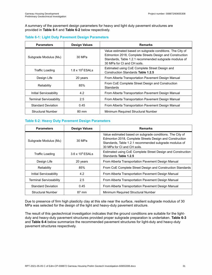
Garneau Housing Development Preliminary Geotechnical Investigation
Project number: 008872/60655308
RPT-2021-05-05 C of Edm-CP-008872 Garneau Housing Prelim Geotech Investigation-60655308.docx 31
A summary of the pavement design parameters for heavy and light duty pavement structures are
provided in Table 6-1 and Table 6-2 below respectively.
Table 6-1: Light Duty Pavement Design Parameters
Parameters Design Values Remarks
Subgrade Modulus (MR) 30 MPa
Value estimated based on subgrade conditions. The City of
Edmonton 2018, Complete Streets Design and Construction
Standards, Table 1.2.1 recommended subgrade modulus of
30 MPa for CI and CH soils.
Traffic Loading 1.8 x 10⁵ ESALs Estimated using CoE Complete Street Design and
Construction Standards Table 1.2.5
Design Life 20 years From Alberta Transportation Pavement Design Manual
Reliability 85% From CoE Complete Street Design and Construction
Standards
Initial Serviceability 4.2 From Alberta Transportation Pavement Design Manual
Terminal Serviceability 2.5 From Alberta Transportation Pavement Design Manual
Standard Deviation 0.45 From Alberta Transportation Pavement Design Manual
Structural Number 80 mm Minimum Required Structural Number
Table 6-2: Heavy Duty Pavement Design Parameters
Parameters Design Values Remarks
Subgrade Modulus (MR) 30 MPa
Value estimated based on subgrade conditions. The City of
Edmonton 2018, Complete Streets Design and Construction
Standards, Table 1.2.1 recommended subgrade modulus of
30 MPa for CI and CH soils.
Traffic Loading 3.6 x 10⁵ ESALs Estimated using CoE Complete Street Design and Construction
Standards Table 1.2.5
Design Life 20 years From Alberta Transportation Pavement Design Manual
Reliability 85% From CoE Complete Street Design and Construction Standards
Initial Serviceability 4.2 From Alberta Transportation Pavement Design Manual
Terminal Serviceability 2.5 From Alberta Transportation Pavement Design Manual
Standard Deviation 0.45 From Alberta Transportation Pavement Design Manual
Structural Number 87 mm Minimum Required Structural Number
Due to presence of firm high plasticity clay at this site near the surface, resilient subgrade modulus of 30 MPa was selected for the design of the light and heavy-duty pavement structure.
The result of this geotechnical investigation indicates that the ground conditions are suitable for the light-
duty and heavy-duty pavement structures provided proper subgrade preparation is undertaken. Table 6-3
and Table 6-4 below summarize the recommended pavement structures for light-duty and heavy-duty
pavement structures respectively.

Garneau Housing Development Preliminary Geotechnical Investigation
Project number: 008872/60655308
RPT-2021-05-05 C of Edm-CP-008872 Garneau Housing Prelim Geotech Investigation-60655308.docx 32
Table 6-3: Light-Duty Pavement Structure
Description Pavement Structure
Material
Pavement Structure
Thickness (mm) Remarks
Light-Duty Pavement Structure
Asphalt Concrete Pavement
100
20 mm-B Asphalt should be placed in two layers. The first layer should be 60 mm and compacted to 94% of Maximum Theoretical Density (MTD) followed by placement of 10mm-LT of 40 mm compacted to 94% of MTD (CoE Complete Streets Design and Construction Standards).
Crushed Granular Base Course over
Non-woven geotextile 300
Designation 3, Class 20 granular material compacted to 100% of SPMDD within ±3% of OMC.
Prepared Subgrade 150
Refer to Section 6.1 for Subgrade Preparation. If the existing exposed subgrade cannot be compacted to 98% of SPMDD, additional subgrade preparation may be required.
Total Pavement Structure above prepared subgrade
400
Table 6-4: Heavy-Duty Pavement Structure
Description Pavement Structure
Material
Pavement Structure
Thickness (mm) Remarks
Heavy-Duty Pavement Structure
Asphalt Concrete Pavement
100
20 mm-B Asphalt should be placed in two layers. The first layer should be 60 mm and compacted to 94% of Maximum Theoretical Density (MTD) followed by placement of 10 mm-LT 40 mm compacted to 94% of MTD (CoE Complete Streets Design and Construction Standards)
Crushed Granular Base Course over
Non-woven geotextile 335
Designation 3, Class 20 granular material compacted to 100% of SPMDD within ±3% of OMC
Prepared Subgrade 150
Refer to Section 6.1 for Subgrade Preparation. If the existing exposed subgrade cannot be compacted to 98% of SPMDD, additional subgrade preparation may be required.
Total Pavement Structure above prepared subgrade
435
The crushed granular base course should be Designation 3, Class 20 granular material in accordance
with CoE Complete Streets Design and Construction Standards.
A non-woven filter fabric should be provided between the base of the granular fill and subgrade to prevent
migration of fine materials into the granular fill.

Garneau Housing Development Preliminary Geotechnical Investigation
Project number: 008872/60655308
RPT-2021-05-05 C of Edm-CP-008872 Garneau Housing Prelim Geotech Investigation-60655308.docx 33
7. Conclusion
The site is considered suitable for the proposed housing building provided that the geotechnical risks
identified during this investigation are understood and recommendations in this report are followed. At the
time of submission of this geotechnical report, the building type, building size, foundation type, and
foundation elevations have not been yet known. Depending on the size of the building and the foundation
depth, strip footings, a raft or deep foundations are likely the most suitable foundation type for this project.
A detailed site investigation is recommended to confirm the bearing capacity and estimate the settlement
of the selected foundation type. A detailed geotechnical investigation may also be an opportunity to
confirm the site seismic classification of this site with a 30 mBGS testhole and seismic cone penetration
test to measure the shear wave velocity profile versus depth. The detailed site investigation should be
completed once the building details are confirmed.
aecom.com

Appendix A Testhole Location Plan

2021-05-05
Appendix B
General Statement; Normal Variability of Subsurface Conditions; Explanation of Field and Laboratory Test Data;
Modified Unified Soil Classification System;
Testhole Logs

AECOM Canada Ltd. General Statement; Normal Variability Of Subsurface Conditions
The scope of the investigation presented herein is limited to an investigation of the subsurface conditions as to suitability of the site for the proposed project. This report has been prepared to aid in the general evaluation of the site and to assist the design engineer in the conceptual design for the area. The description of the project presented in this report represents the understanding by the geotechnical engineer of the significant aspects of the project relevant to the design and construction of the subdivision, infrastructure and similar. In the event of any changes in the basic design or location of the structures, as outlined in this report or plan, AECOM should be given the opportunity to review the changes and to modify or reaffirm in writing the conclusions and recommendations of this report. The analysis and recommendations represented in this report are based on the data obtained from the test holes drilled at the locations indicated on the site plans and from other information discussed herein. This report is based on the assumption that the subsurface conditions everywhere on the site are not significantly different from those encountered at the test locations. However, variations in soil conditions may exist between the test holes and, also, general groundwater levels and condition may fluctuate from time to time. The nature and extent of the variations may not become evident until construction. If subsurface conditions, different from those encountered in the test holes are observed or encountered during construction or appear to be present beneath or beyond the excavation, AECOM should be advised at once so that the conditions can be observed and reviewed and the recommendations reconsidered where necessary. Since it is possible for conditions to vary from those identified at the test locations and from those assumed in the analysis and preparation of recommendations, a contingency fund should be included in the construction budget to allow for the possibility of variations which may result in modifications of the design and construction procedures.

Explanation of Field Lab Data (February 2021).docx FEBRUARY 2021
EXPLANATION OF FIELD & LABORATORY TEST DATA
The field and laboratory test results, as shown for each hole, are described below.
1. NATURAL MOISTURE CONTENT
The relationship between the natural moisture content and depth is significant in determining the
subsurface moisture conditions. The Atterberg Limits for a sample should be compared to its natural
moisture content and plotted on the Plasticity Chart in order to determine the soil classification.
2. SOIL PROFILE AND DESCRIPTION
Each soil stratum is classified and described noting any special conditions. The Modified Unified
Classification System (MUCS) is used. The soil profile refers to the existing ground level at the time the
hole was done. Where available, the ground elevation is shown. The soil symbols used are shown in
detail on the soil classification chart.
3. TESTS ON SOIL SAMPLES
Laboratory and field tests are identified by the following and are on the logs:
N - Standard Penetration Test (SPT) Blow Count. The SPT is conducted in the field to assess thein-situ consistency of cohesive soils and the relative density of non-cohesive soils. The N
value recorded is the number of blows from a 63.5 kg hammer dropped 760 mm which is
required to drive a 51 mm split spoon sampler 300 mm into the soil.
SO4 - Water Soluble Sulphate Content. Expressed in percent. Conducted primarily to determine
requirements for the use of sulphate resistant cement. Further details on the water-soluble
sulphate content are given in Section 6.
gD - Dry Unit Weight. Usually expressed in kN/m3.
gT - Total Unit Weight. Usually expressed in kN/m3.
QU - Unconfined Compressive Strength. Usually expressed in kPa and may be used in determining
allowable bearing capacity of the soil.
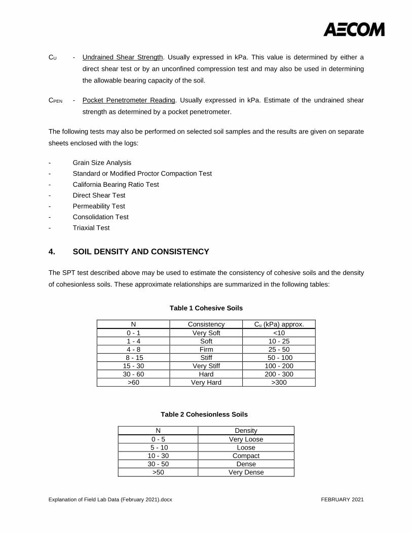
Explanation of Field Lab Data (February 2021).docx FEBRUARY 2021
CU - Undrained Shear Strength. Usually expressed in kPa. This value is determined by either a
direct shear test or by an unconfined compression test and may also be used in determining
the allowable bearing capacity of the soil.
CPEN - Pocket Penetrometer Reading. Usually expressed in kPa. Estimate of the undrained shear
strength as determined by a pocket penetrometer.
The following tests may also be performed on selected soil samples and the results are given on separate
sheets enclosed with the logs:
- Grain Size Analysis- Standard or Modified Proctor Compaction Test- California Bearing Ratio Test- Direct Shear Test- Permeability Test- Consolidation Test- Triaxial Test
4. SOIL DENSITY AND CONSISTENCY
The SPT test described above may be used to estimate the consistency of cohesive soils and the density
of cohesionless soils. These approximate relationships are summarized in the following tables:
Table 1 Cohesive Soils
N Consistency Cu (kPa) approx.0 - 1 Very Soft <101 - 4 Soft 10 - 254 - 8 Firm 25 - 50
8 - 15 Stiff 50 - 10015 - 30 Very Stiff 100 - 20030 - 60 Hard 200 - 300
>60 Very Hard >300
Table 2 Cohesionless Soils
N Density0 - 5 Very Loose
5 - 10 Loose10 - 30 Compact30 - 50 Dense
>50 Very Dense

Explanation of Field Lab Data (February 2021).docx FEBRUARY 2021
5. SAMPLE CONDITION AND TYPE
The depth, type, and condition of samples are indicated on the logs by the following symbols:
6. WATER SOLUBLE SULPHATE CONCENTRATION
The following table, from CSA Standard A23.1-14, indicates the requirements for concrete subjected tosulphate attack based upon the percentage of water-soluble sulphate as presented on the logs. CSA
Standard A23.1-14 should be read in conjunction with the table.
Table 3 Requirements for Concrete Subjected to Sulphate Attack*
*For sea water exposure, also see Clause 4.1.1.5.†In accordance with CSA A23.2-3B.‡In accordance with CSA A23.2-2B.§Where combinations of supplementary cementing materials and portland or blended hydraulic cements are to be used in theconcrete mix design instead of the cementing materials listed, and provided they meet the performance requirementsdemonstrating equivalent performance against sulphate exposure, they shall be designated as MS equivalent (MSe) or HSequivalent (HSe) in the relevant sulphate exposures (see Clauses 4.1.1.6.2, 4.2.1.1, and 4.2.1.3, and 4.2.1.4).**Type HS cement shall not be used in reinforced concrete exposed to both chlorides and sulphates, including seawater. SeeClause 4.1.1.6.3.††The requirement for testing at 5 °C does not apply to MS, HS, MSb, HSb, and MSe and HSe combinations made withoutportland limestone cement.‡‡ If the increase in expansion between 12 and 18 months exceeds 0.03%, the sulphate expansion at 24 months shall notexceed 0.10% in order for the cement to be deemed to have passed the sulphate resistance requirement.§§For demonstrating equivalent performance, use the testing frequency in Table 1 of CSA A3004-A1 and see the applicablenotes to Table A3 in A3001 with regard to re-establishing compliance if the composition of the cementing materials used toestablish compliance changes.
Grab
No Recovery
Split Spoon
Bulk
Shelby Tube
Core Sample

Explanation of Field Lab Data (February 2021).docx FEBRUARY 2021
***Where MSLb or HSLb cements are proposed for use, or where MSe or HSe combinations include Portland-limestone cement,they must also contain a minimum of 25% Type F fly ash or 40% slag or 15% metakaolin (meeting Type N pozzolanrequirements) or a combination of 5% Type SF silica fume with 25% slag or a combination of 5% Type SF silica fume with 20%Type F fly ash. For some proposed MSLb, HSLb, and MSe or HSe combinations that include Portland-limestone cement, higherSCM replacement levels may be required to meet the A3004-C8 Procedure B expansion limits. Due to the 18-month test period,SCM replacements higher than the identified minimum levels should also be tested. In addition, sulphate resistance testing shallbe run on MSLb and HSLb cement and MSe or HSe combinations that include Portland-limestone cement at both 23 °C and 5°C as specified in the table.†††If the expansion is greater than 0.05% at 6 months but less than 0.10% at 1 year, the cementing materials combination undertest shall be considered to have passed.
7. SOIL CORROSIVITY
The following table, from the Handbook of Corrosion Engineering (Roberge, 1999) indicates the
corrosivity rating can be obtained from the soil resistivity, presented on the logs.
Table 4 Corrosivity Ratings Based on Soil Resistivity
Soil Resistivity (ohm-cm) Corrosivity Rating>20,000 Essentially non-corrosive
10,000 – 20,000 Mildly corrosive5,000 – 10,000 Moderately corrosive3,000 – 5,000 Corrosive1,000 – 3,000 Highly corrosive
<1,000 Extremely corrosive
8. GROUNDWATER TABLE
The groundwater table is indicated by the equilibrium level of water in a standpipe installed in a testhole
or test pit. This level is generally taken at least 24 hours after installation of the standpipe. The
groundwater level is subject to seasonal variations and is usually highest in the spring. The symbol on the
logs indicating the groundwater level is an inverted solid triangle (▼).
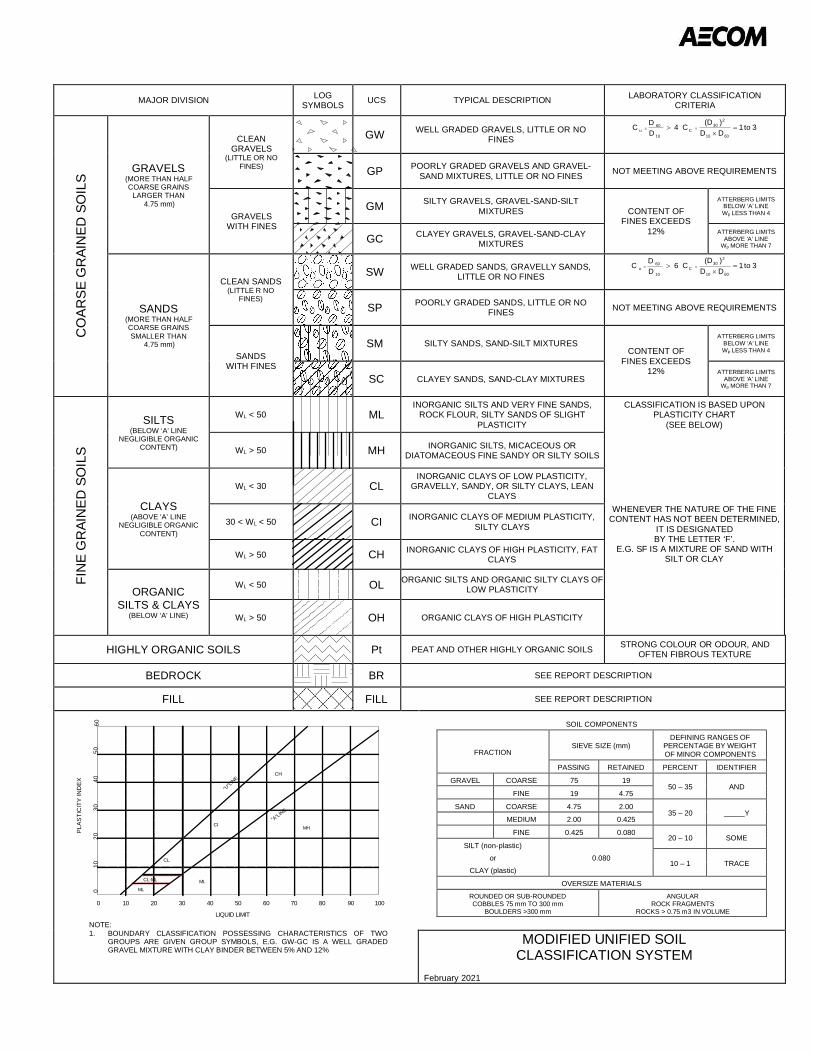
MAJOR DIVISION LOGSYMBOLS UCS TYPICAL DESCRIPTION LABORATORY CLASSIFICATION
CRITERIA
CO
ARSE
GR
AIN
ED S
OIL
S
GRAVELS(MORE THAN HALFCOARSE GRAINS
LARGER THAN 4.75 mm)
CLEANGRAVELS
(LITTLE OR NOFINES)
GW WELL GRADED GRAVELS, LITTLE OR NOFINES
4DDC
10
60=u > 3to1
DD)(DC
6010
230
=C =´
GP POORLY GRADED GRAVELS AND GRAVEL-SAND MIXTURES, LITTLE OR NO FINES NOT MEETING ABOVE REQUIREMENTS
GRAVELSWITH FINES
GM SILTY GRAVELS, GRAVEL-SAND-SILTMIXTURES CONTENT OF
FINES EXCEEDS12%
ATTERBERG LIMITSBELOW ‘A’ LINEWp LESS THAN 4
GC CLAYEY GRAVELS, GRAVEL-SAND-CLAYMIXTURES
ATTERBERG LIMITSABOVE ‘A’ LINE
Wp MORE THAN 7
SANDS(MORE THAN HALFCOARSE GRAINSSMALLER THAN
4.75 mm)
CLEAN SANDS(LITTLE R NO
FINES)
SW WELL GRADED SANDS, GRAVELLY SANDS,LITTLE OR NO FINES
6DDC
10
60=u > 3to1
DD)(DC
6010
230
=C =´
SP POORLY GRADED SANDS, LITTLE OR NOFINES NOT MEETING ABOVE REQUIREMENTS
SANDSWITH FINES
SM SILTY SANDS, SAND-SILT MIXTURESCONTENT OF
FINES EXCEEDS12%
ATTERBERG LIMITSBELOW ‘A’ LINEWp LESS THAN 4
SC CLAYEY SANDS, SAND-CLAY MIXTURESATTERBERG LIMITS
ABOVE ‘A’ LINEWp MORE THAN 7
FIN
E G
RAI
NED
SO
ILS
SILTS(BELOW ‘A’ LINE
NEGLIGIBLE ORGANICCONTENT)
WL < 50 MLINORGANIC SILTS AND VERY FINE SANDS,
ROCK FLOUR, SILTY SANDS OF SLIGHTPLASTICITY
CLASSIFICATION IS BASED UPONPLASTICITY CHART
(SEE BELOW)
WL > 50 MH INORGANIC SILTS, MICACEOUS ORDIATOMACEOUS FINE SANDY OR SILTY SOILS
WHENEVER THE NATURE OF THE FINECONTENT HAS NOT BEEN DETERMINED,
IT IS DESIGNATEDBY THE LETTER ‘F’.
E.G. SF IS A MIXTURE OF SAND WITHSILT OR CLAY
CLAYS(ABOVE ‘A’ LINE
NEGLIGIBLE ORGANICCONTENT)
WL < 30 CLINORGANIC CLAYS OF LOW PLASTICITY,
GRAVELLY, SANDY, OR SILTY CLAYS, LEANCLAYS
30 < WL < 50 CI INORGANIC CLAYS OF MEDIUM PLASTICITY,SILTY CLAYS
WL > 50 CH INORGANIC CLAYS OF HIGH PLASTICITY, FATCLAYS
ORGANICSILTS & CLAYS
(BELOW ‘A’ LINE)
WL < 50 OL ORGANIC SILTS AND ORGANIC SILTY CLAYS OFLOW PLASTICITY
WL > 50 OH ORGANIC CLAYS OF HIGH PLASTICITY
HIGHLY ORGANIC SOILS Pt PEAT AND OTHER HIGHLY ORGANIC SOILS STRONG COLOUR OR ODOUR, ANDOFTEN FIBROUS TEXTURE
BEDROCK BR SEE REPORT DESCRIPTION
FILL FILL SEE REPORT DESCRIPTION
SOIL COMPONENTS
FRACTIONSIEVE SIZE (mm)
DEFINING RANGES OFPERCENTAGE BY WEIGHTOF MINOR COMPONENTS
PASSING RETAINED PERCENT IDENTIFIER
GRAVEL COARSE 75 1950 – 35 AND
FINE 19 4.75
SAND COARSE 4.75 2.0035 – 20 _____Y
MEDIUM 2.00 0.425
FINE 0.425 0.08020 – 10 SOME
SILT (non-plastic)or
CLAY (plastic)0.080
10 – 1 TRACE
OVERSIZE MATERIALSROUNDED OR SUB-ROUNDEDCOBBLES 75 mm TO 300 mm
BOULDERS >300 mm
ANGULARROCK FRAGMENTS
ROCKS > 0.75 m3 IN VOLUME
MODIFIED UNIFIED SOILCLASSIFICATION SYSTEM
February 2021
CL
CI
CH
MH
MLML
CL-ML
"A"LINE
"U"LI
NE
0 10 403020 50 60 908070 100
010
4030
2050
60
LIQUID LIMIT
PLAS
TIC
ITY
IND
EX
NOTE:1. BOUNDARY CLASSIFICATION POSSESSING CHARACTERISTICS OF TWO
GROUPS ARE GIVEN GROUP SYMBOLS, E.G. GW-GC IS A WELL GRADEDGRAVEL MIXTURE WITH CLAY BINDER BETWEEN 5% AND 12%

3TM ZONE:
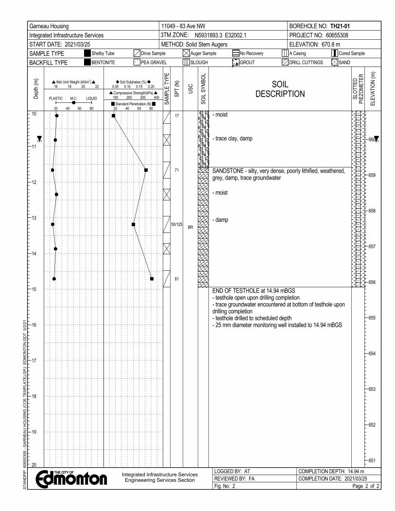
3TM ZONE:

3TM ZONE:

3TM ZONE:
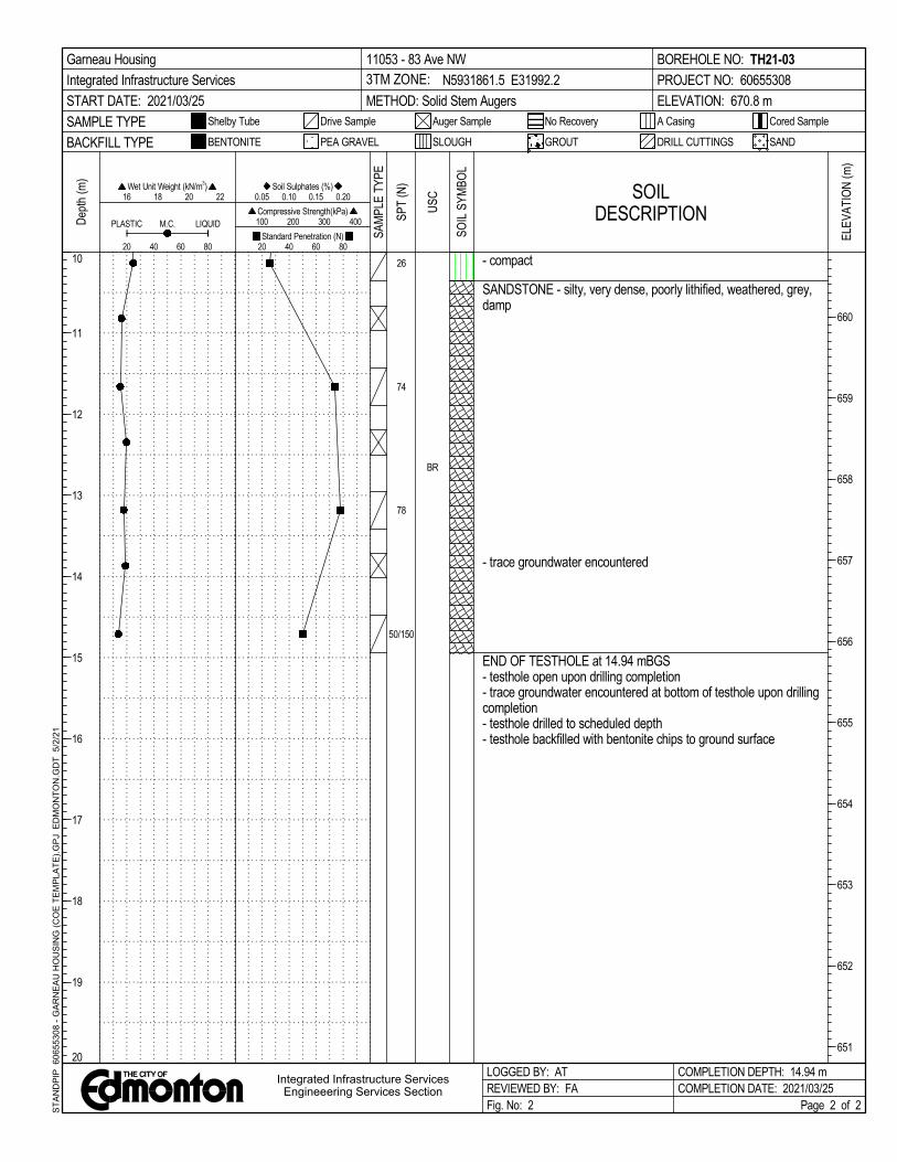
3TM ZONE:

Appendix C
Laboratory Results

WATER CONTENT (ASTM D2216)CLIENT:
PROJECT: Garneau Housing
JOB No.:
DATE : CK/GU
HOLE No. 21-01
DEPTH
SAMPLE No. 1 2 3 4 5 6 7 8
TARE No.
WT. SAMPLE WET + TARE 518.0 577.8 566.3 240.0 613.9 378.2 605.3 593.8
WT. SAMPLE DRY + TARE 412.8 464.0 461.7 189.4 487.4 299.2 468.7 527.6
WT. TARE 13.2 13.2 13.2 13.2 13.2 13.2 13.2 13.2
WATER CONTENT W% 26.3% 25.2% 23.3% 28.7% 26.7% 27.6% 30.0% 12.9%HOLE No. 21-01
DEPTH
SAMPLE No. 9 10 11 12 13 14 15 16
TARE No.
WT. SAMPLE WET + TARE 505.0 523.8 511.5 566.6 448.0 652.8 788.1 546.0
WT. SAMPLE DRY + TARE 454.5 446.4 453.3 514.9 399.3 539.1 663.3 479.3
WT. TARE 13.2 13.2 13.2 13.2 13.2 13.2 13.2 13.2
WATER CONTENT W% 11.4% 17.9% 13.2% 10.3% 12.6% 21.6% 19.2% 14.3%HOLE No. 21-01 21-02
DEPTH
SAMPLE No. 17 18 19 20 1 2 3 4
TARE No.
WT. SAMPLE WET + TARE 713.8 774.2 880.8 724.2 614.7 339.1 654.4 621.7
WT. SAMPLE DRY + TARE 592.1 676.5 740.0 620.9 535.2 271.5 508.4 481.4
WT. TARE 13.2 13.2 13.2 13.2 13.2 13.2 13.2 13.2
WATER CONTENT W% 21.0% 14.7% 19.4% 17.0% 15.2% 26.2% 29.5% 30.0%HOLE No. 21-02 21-03
DEPTH
SAMPLE No. 5 6 7 8 9 1 2 3
TARE No.
WT. SAMPLE WET + TARE 608.5 625.6 600.5 549.4 352.6 465.1 430.7 674.0
WT. SAMPLE DRY + TARE 455.1 469.9 450.7 461.1 297.3 358.4 339.6 531.8
WT. TARE 13.2 13.2 13.2 13.2 13.2 13.2 13.2 13.2
WATER CONTENT W% 34.7% 34.1% 34.2% 19.7% 19.5% 30.9% 27.9% 27.4%
City of Edmonton
60655308
March 29, 2021 TECHNICAN :
FORM : COE Garneau Moisture Contents .xlsDATE: 4/19/2021
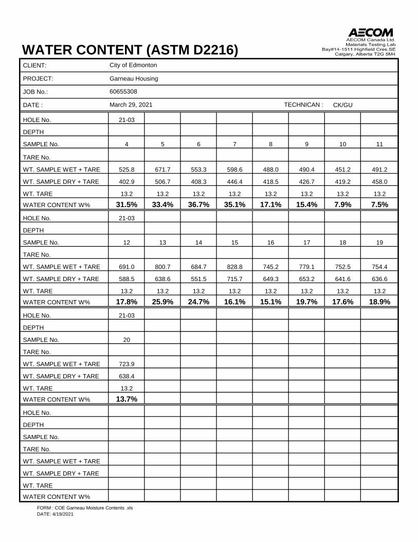
WATER CONTENT (ASTM D2216)CLIENT:
PROJECT: Garneau Housing
JOB No.:
DATE : CK/GU
HOLE No. 21-03
DEPTH
SAMPLE No. 4 5 6 7 8 9 10 11
TARE No.
WT. SAMPLE WET + TARE 525.8 671.7 553.3 598.6 488.0 490.4 451.2 491.2
WT. SAMPLE DRY + TARE 402.9 506.7 408.3 446.4 418.5 426.7 419.2 458.0
WT. TARE 13.2 13.2 13.2 13.2 13.2 13.2 13.2 13.2
WATER CONTENT W% 31.5% 33.4% 36.7% 35.1% 17.1% 15.4% 7.9% 7.5%HOLE No. 21-03
DEPTH
SAMPLE No. 12 13 14 15 16 17 18 19
TARE No.
WT. SAMPLE WET + TARE 691.0 800.7 684.7 828.8 745.2 779.1 752.5 754.4
WT. SAMPLE DRY + TARE 588.5 638.6 551.5 715.7 649.3 653.2 641.6 636.6
WT. TARE 13.2 13.2 13.2 13.2 13.2 13.2 13.2 13.2
WATER CONTENT W% 17.8% 25.9% 24.7% 16.1% 15.1% 19.7% 17.6% 18.9%HOLE No. 21-03
DEPTH
SAMPLE No. 20
TARE No.
WT. SAMPLE WET + TARE 723.9
WT. SAMPLE DRY + TARE 638.4
WT. TARE 13.2
WATER CONTENT W% 13.7%HOLE No.
DEPTH
SAMPLE No.
TARE No.
WT. SAMPLE WET + TARE
WT. SAMPLE DRY + TARE
WT. TARE
WATER CONTENT W%
City of Edmonton
60655308
March 29, 2021 TECHNICAN :
FORM : COE Garneau Moisture Contents .xlsDATE: 4/19/2021

ATTERBERG LIMITS (ASTM D4318)CLIENT : City of Edmonton
PROJECT :JOB No. :LOCATION :TESTHOLE:DATE :
123
50.5235.3814.3921.015.1
72.1%
Liquid Limit 71.4 1Plastic Limit 21.1Plasticity Index 50.3 23.88
21.7811.82
Classification: CH 10.0
2.121.1%Water Content (%)
Wt. Sample (wet+tare)(g)Wt. Sample (dry+tare)(g)Wt. Tare (g)Wt. Dry Soil (g)
SAMPLE DESCRIPTION
Wt. Water (g)
Wt. Water (g)Water Content (%)
AVERAGE VALUES PLASTIC LIMITTrial No.Container Number
Number of BlowsContainer NumberWt. Sample (wet+tare)(g)Wt. Sample (dry+tare)(g)Wt. Tare (g)Wt. Dry Soil (g)
GU
SAMPLE:
Trial No.
21-01April 26, 2021
DEPTH :TECHNICIAN :
LIQUID LIMIT
Garneau Housing60655308
3
0
10
20
30
40
50
60
0 10 20 30 40 50 60 70 80 90 100
PLAS
TIC
ITY
IND
EX
LIQUID LIMIT
CI
CH
MH
ML
CL
CL-ML
FORM: COE Garneau TH21-01 #3 Atterberg .xlsDATE: 4/27/2021

ATTERBERG LIMITS (ASTM D4318)CLIENT : City of Edmonton
PROJECT :JOB No. :LOCATION :TESTHOLE:DATE :
130
62.4054.8816.2238.77.5
19.5%
Liquid Limit 19.9 1Plastic Limit 18.6Plasticity Index 1.3 31.36
28.3111.90
Classification: ML 16.4
3.118.6%
Garneau Housing60655308
9
GU
SAMPLE:
Trial No.
21-01March 31, 2021
DEPTH :TECHNICIAN :
LIQUID LIMIT
Number of BlowsContainer NumberWt. Sample (wet+tare)(g)Wt. Sample (dry+tare)(g)Wt. Tare (g)Wt. Dry Soil (g)Wt. Water (g)Water Content (%)
AVERAGE VALUES PLASTIC LIMITTrial No.Container NumberWt. Sample (wet+tare)(g)Wt. Sample (dry+tare)(g)Wt. Tare (g)Wt. Dry Soil (g)
SAMPLE DESCRIPTION
Wt. Water (g)Water Content (%)
0
10
20
30
40
50
60
0 10 20 30 40 50 60 70 80 90 100
PLAS
TIC
ITY
IND
EX
LIQUID LIMIT
CI
CH
MH
ML
CL
CL-ML
FORM: COE Garneau TH21-01 #9 Atterberg .xlsDATE: 4/19/2021

ATTERBERG LIMITS (ASTM D4318)CLIENT : City of Edmonton
PROJECT :JOB No. :LOCATION :TESTHOLE:DATE :
130
41.5829.8311.9317.911.8
65.6%
Liquid Limit 67.1 1Plastic Limit 21.9Plasticity Index 45.2 29.32
26.9716.22
Classification: CH 10.8
2.421.9%
Garneau Housing60655308
3
CK
SAMPLE:
Trial No.
21-03March 31, 2021
DEPTH :TECHNICIAN :
LIQUID LIMIT
Number of BlowsContainer NumberWt. Sample (wet+tare)(g)Wt. Sample (dry+tare)(g)Wt. Tare (g)Wt. Dry Soil (g)Wt. Water (g)Water Content (%)
AVERAGE VALUES PLASTIC LIMITTrial No.Container NumberWt. Sample (wet+tare)(g)Wt. Sample (dry+tare)(g)Wt. Tare (g)Wt. Dry Soil (g)
SAMPLE DESCRIPTION
Wt. Water (g)Water Content (%)
0
10
20
30
40
50
60
0 10 20 30 40 50 60 70 80 90 100
PLAS
TIC
ITY
IND
EX
LIQUID LIMIT
CI
CH
MH
ML
CL
CL-ML
FORM: COE Garneau TH21-03 #3 Atterberg .xlsDATE: 4/19/2021

ATTERBERG LIMITS (ASTM D4318)CLIENT : City of Edmonton
PROJECT :JOB No. :LOCATION :TESTHOLE:DATE :
118
63.4553.6315.9737.79.8
26.1%
Liquid Limit 25.1 1Plastic Limit 20.6Plasticity Index 4.5 34.73
30.8511.97
Classification: CL-ML 18.9
3.920.6%
Garneau Housing60655308
8
GU
SAMPLE:
Trial No.
21-03March 31, 2021
DEPTH :TECHNICIAN :
LIQUID LIMIT
Number of BlowsContainer NumberWt. Sample (wet+tare)(g)Wt. Sample (dry+tare)(g)Wt. Tare (g)Wt. Dry Soil (g)Wt. Water (g)Water Content (%)
AVERAGE VALUES PLASTIC LIMITTrial No.Container NumberWt. Sample (wet+tare)(g)Wt. Sample (dry+tare)(g)Wt. Tare (g)Wt. Dry Soil (g)
SAMPLE DESCRIPTION
Wt. Water (g)Water Content (%)
0
10
20
30
40
50
60
0 10 20 30 40 50 60 70 80 90 100
PLAS
TIC
ITY
IND
EX
LIQUID LIMIT
CI
CH
MH
ML
CL
CL-ML
FORM: COE Garneau TH21-03 #8 Atterberg .xlsDATE: 4/19/2021

GRAIN SIZE ANALYSIS (ASTM D422)CLIENT :PROJECT : Garneau HousingJOB No. : 60655308LOCATION :TESTHOLE:DATE :
Before Washing 150,000 6 150.0 0% 100%Wet + Tare 75,000 3 75.0 0% 100%Dry+Tare 538.5 50,000 2 50.0 0% 100%Tare 100.0 40,000 1 1/2 40.0 0% 100%Wt. Dry 438.5 25,000 1 25.0 0% 100%Moisture Content 20,000 3/4 20.0 0% 100%Wet + Tare 16,000 5/8 16.0 0% 100%Dry+Tare 12,500 1/2 12.5 0% 100%Tare 10,000 3/8 10.0 0% 100%MC (%) 5,000 0.185 5.0 0% 100%
PassingAfter Washing 2,000 0.0937 2.0 0% 100%Wt. Dry+Tare 1,250 0.0469 1.25 0.9 0% 99.8%Tare 630 0.0234 0.63 1.8 0% 99.6%Wt. Dry 315 0.0116 0.315 3.5 1% 99.2%Tare No. 160 0.0059 0.160 7.9 2% 98.2%
75 0.00295 0.075 104.4 24% 76.2%PAN
Wt Dry+Tare 538.5 39 0.5 0.059 21 35 68.8%Wt Tare 100.0 32 1 0.044 21 28 54.9%Wt Dry 438.5 27 2 0.032 21 23 45.0%Sample Size : 50 21 5 0.021 21 17 33.2%Wt Retained 2 mm: 0.0 17 15 0.013 21 13 25.2%% Passing 2 mm: 100.0% 16 30 0.009 21 12 23.3%Specific Gravity : 2.70 15 60 0.006 21 11 21.3%Hydrometer No.: 43-9856 14 120 0.005 21 10 19.3%Solution (g/L) : 40 13 240 0.003 21 9 17.3%
12 1440 0.001 21 8 15.3%12 2880 0.001 21 7 14.4%
City of Edmonton
21-01March 30, 2021 GU
SAMPLE:DEPTH :TECHNICIAN :
9
PERCENT FINERTHAN
APPROX.INCHES mm
WEIGHTRETAINED (g)
SIZE OF OPENINGREMARKSPERCENT
RETAINEDPERCENT FINER
THAN SIEVE NO. (m)TOTAL DRY WEIGHT OF SAMPLE
REMARKSHYDROMETER DATA READING TIME (min) DIAMETER (mm) TEMP. (°C) CORR. READING
FORM: COE Garneau TH21-01 #9 Hydro .xlsDATE: 4/19/2021

GRAIN SIZE ANALYSIS (ASTM D422)CLIENT :PROJECT : Garneau HousingJOB No. : 60655308LOCATION :TESTHOLE:DATE :
City of Edmonton
21-01March 30, 2021 GU
SAMPLE:DEPTH :TECHNICIAN :
9
SIZE OF OPENINGGravel = 0.0% Sand = 23.8% Silt = 59.9% Clay = 16.3%
0%
10%
20%
30%
40%
50%
60%
70%
80%
90%
100%
0.00
1
0.01
0.1
110100
1000
% F
INER
TH
AN
SIEVE SIZE (mm)
aCobblesa Gravel SandCoarse Fine Coarse Medium Fine aSilt or Claya
FORM: COE Garneau TH21-01 #9 Hydro .xlsDATE: 4/19/2021

GRAIN SIZE ANALYSIS (ASTM D422)CLIENT :PROJECT : Garneau HousingJOB No. : 60655308LOCATION :TESTHOLE:DATE :
Before Washing 150,000 6 150.0 0% 100%Wet + Tare 75,000 3 75.0 0% 100%Dry+Tare 460.7 50,000 2 50.0 0% 100%Tare 100.0 40,000 1 1/2 40.0 0% 100%Wt. Dry 360.7 25,000 1 25.0 0% 100%Moisture Content 20,000 3/4 20.0 0% 100%Wet + Tare 16,000 5/8 16.0 0% 100%Dry+Tare 12,500 1/2 12.5 0% 100%Tare 10,000 3/8 10.0 0% 100%MC (%) 5,000 0.185 5.0 0% 100%
PassingAfter Washing 2,000 0.0937 2.0 0% 100%Wt. Dry+Tare 1,250 0.0469 1.25 0% 100%Tare 630 0.0234 0.63 0.4 0% 99.9%Wt. Dry 315 0.0116 0.315 0.7 0% 99.8%Tare No. 160 0.0059 0.160 6.5 2% 98.2%
75 0.00295 0.075 166.6 46% 53.8%PAN
Wt Dry+Tare 460.7 44 0.5 0.055 23 40 39.8%Wt Tare 100.0 35 1 0.042 23 31 30.9%Wt Dry 360.7 25 2 0.032 23 21 21.0%Sample Size : 100 19 5 0.021 23 15 15.1%Wt Retained 2 mm: 0.0 17 15 0.012 23 13 13.1%% Passing 2 mm: 100.0% 15 30 0.009 23 11 11.1%Specific Gravity : 2.70 14 60 0.006 23 10 10.1%Hydrometer No.: 43-9856 14 120 0.004 23 10 9.7%Solution (g/L) : 40 13 240 0.003 23 9 8.7%
11 1440 0.001 21 7 6.7%11 2880 0.001 21 6 6.2%
SIEVE NO. (m)TOTAL DRY WEIGHT OF SAMPLE
REMARKSHYDROMETER DATA READING TIME (min) DIAMETER (mm) TEMP. (°C) CORR. READING PERCENT FINERTHAN
APPROX.INCHES mm
WEIGHTRETAINED (g)
SIZE OF OPENINGREMARKSPERCENT
RETAINEDPERCENT FINER
THAN
City of Edmonton
21-01April 14, 2021 CK
SAMPLE:DEPTH :TECHNICIAN :
1330-31'
FORM: COE Garneau TH21-01 #13 Hydro .xlsDATE: 4/19/2021

GRAIN SIZE ANALYSIS (ASTM D422)CLIENT :PROJECT : Garneau HousingJOB No. : 60655308LOCATION :TESTHOLE:DATE :
SIZE OF OPENING
City of Edmonton
21-01April 14, 2021 CK
SAMPLE:DEPTH :TECHNICIAN :
1330-31'
Gravel = 0.0% Sand = 46.2% Silt = 46.1% Clay = 7.7%
0%
10%
20%
30%
40%
50%
60%
70%
80%
90%
100%
0.00
1
0.01
0.1
110100
1000
% F
INER
TH
AN
SIEVE SIZE (mm)
aCobblesa Gravel SandCoarse Fine Coarse Medium Fine aSilt or Claya
FORM: COE Garneau TH21-01 #13 Hydro .xlsDATE: 4/19/2021

GRAIN SIZE ANALYSIS (ASTM D422)CLIENT :PROJECT : Garneau HousingJOB No. : 60655308LOCATION :TESTHOLE:DATE :
Before Washing 150,000 6 150.0 0% 100%Wet + Tare 75,000 3 75.0 0% 100%Dry+Tare 673.3 50,000 2 50.0 0% 100%Tare 100.0 40,000 1 1/2 40.0 0% 100%Wt. Dry 573.3 25,000 1 25.0 0% 100%Moisture Content 20,000 3/4 20.0 0% 100%Wet + Tare 16,000 5/8 16.0 0% 100%Dry+Tare 12,500 1/2 12.5 0% 100%Tare 10,000 3/8 10.0 0% 100%MC (%) 5,000 0.185 5.0 2.6 0% 99.5%
PassingAfter Washing 2,000 0.0937 2.0 2.8 0% 99.5%Wt. Dry+Tare 1,250 0.0469 1.25 2.8 0% 99.5%Tare 630 0.0234 0.63 5.1 1% 99.1%Wt. Dry 315 0.0116 0.315 8.5 1% 98.5%Tare No. 160 0.0059 0.160 30.2 5% 94.7%
75 0.00295 0.075 124.9 22% 78.2%PAN
Wt Dry+Tare 673.3 41 0.5 0.058 21 37 72.4%Wt Tare 100.0 37 1 0.042 21 33 64.5%Wt Dry 573.3 31 2 0.031 21 27 52.7%Sample Size : 50 24 5 0.021 21 20 38.9%Wt Retained 2 mm: 2.8 17 15 0.013 21 13 25.1%% Passing 2 mm: 99.5% 15 30 0.009 21 11 21.2%Specific Gravity : 2.70 13 60 0.006 21 9 17.2%Hydrometer No.: 43-9856 12 120 0.005 21 8 15.3%Solution (g/L) : 40 11 240 0.003 21 7 13.3%
10 1440 0.001 21 6 11.3%10 2880 0.001 21 5 10.3%
City of Edmonton
21-03March 30, 2021 GU
SAMPLE:DEPTH :TECHNICIAN :
12
PERCENT FINERTHAN
APPROX.INCHES mm
WEIGHTRETAINED (g)
SIZE OF OPENINGREMARKSPERCENT
RETAINEDPERCENT FINER
THAN SIEVE NO. (m)TOTAL DRY WEIGHT OF SAMPLE
REMARKSHYDROMETER DATA READING TIME (min) DIAMETER (mm) TEMP. (°C) CORR. READING
FORM: COE Garneau TH21-03 #12 Hydro .xlsDATE: 4/19/2021
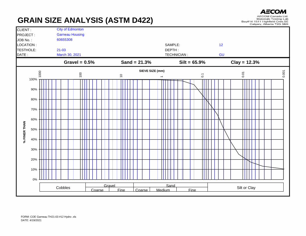
GRAIN SIZE ANALYSIS (ASTM D422)CLIENT :PROJECT : Garneau HousingJOB No. : 60655308LOCATION :TESTHOLE:DATE :
City of Edmonton
21-03March 30, 2021 GU
SAMPLE:DEPTH :TECHNICIAN :
12
SIZE OF OPENINGGravel = 0.5% Sand = 21.3% Silt = 65.9% Clay = 12.3%
0%
10%
20%
30%
40%
50%
60%
70%
80%
90%
100%
0.00
1
0.01
0.1
110100
1000
% F
INER
TH
AN
SIEVE SIZE (mm)
aCobblesa Gravel SandCoarse Fine Coarse Medium Fine aSilt or Claya
FORM: COE Garneau TH21-03 #12 Hydro .xlsDATE: 4/19/2021

[This report shall not be reproduced except in full without the written authority of the Laboratory.]
29-MAR-21
Lab Work Order #: L2571396
Date Received:AECOM Canada Ltd.
Suite 300, 48 Quarry Park Blvd SECalgary AB T2C 5P2
ATTN: Chris KeeleyFINAL 07-APR-21 17:03 (MT)Report Date:
Version:
Certificate of Analysis
ALS CANADA LTD Part of the ALS Group An ALS Limited Company
____________________________________________
Inayat DhaliwalAccount Manager
ADDRESS: 2559 29 Street NE, Calgary, AB T1Y 7B5 Canada | Phone: +1 403 291 9897 | Fax: +1 403 291 0298
Client Phone: 403-254-3301
Total Sulphate Ion Content results are <0.2% for all samples. Water Soluble Sulphate Ion Content test is not required unless Total Sulphate Ion Content result is greater than 0.2%. Water Soluble Sulphate Ion Content analyses have been removed.
Comments:
CITY OF EDMONTON - GARNEAU - 60655308 LAB TESTING
Job Reference: NOT SUBMITTEDProject P.O. #:
C of C Numbers:Legal Site Desc:

ALS ENVIRONMENTAL ANALYTICAL REPORT
L2571396 CONTD....2PAGE
Result D.L. Units Extracted AnalyzedSample Details/Parameters
ofCITY OF EDMONTON - GARNEAU - 60655308 LAB TESTING
Qualifier* Batch
* Refer to Referenced Information for Qualifiers (if any) and Methodology.
Version: FINAL 3
L2571396-1
L2571396-2
CITY OF EDMONTON - GARNEAU - TH21-01 #7
CITY OF EDMONTON - GARNEAU - TH21-03 #10
N/A on 29-MAR-21
N/A on 29-MAR-21
Sampled By:
Sampled By:
SOIL
SOIL
Miscellaneous Parameters
Miscellaneous Parameters
% SaturationChloride (Cl)ResistivitySulfur (as SO4)Total Sulphate Ion ContentpH in Saturated Paste
Chloride (Cl)Sulfur (as SO4)
% SaturationChloride (Cl)ResistivitySulfur (as SO4)Total Sulphate Ion ContentpH in Saturated Paste
Chloride (Cl)Sulfur (as SO4)
%mg/L
ohm cmmg/L
%pH
mg/kgmg/kg
%mg/L
ohm cmmg/L
%pH
mg/kgmg/kg
01-APR-21
01-APR-21
01-APR-21
01-APR-21
01-APR-2105-APR-2101-APR-2104-APR-2101-APR-2101-APR-21
07-APR-2107-APR-21
01-APR-2105-APR-2101-APR-2104-APR-2101-APR-2101-APR-21
07-APR-2107-APR-21
65.523
1640170
<0.0507.66
15111
36.159
15501530
<0.0507.56
21.4551
Salinity in mg/kg
Salinity in mg/kg
1.0201.06.0
0.0500.10
133.9
1.0201.06.0
0.0500.10
7.22.2
Matrix:
Matrix:
R5418837R5419380R5418438R5420347R5418713R5418571
R5418837R5419380R5418438R5420347R5418713R5418571

CL-PASTE-COL-CL
PH-PASTE-CL
RESISTIVITY-PASTE-CL
SAL-MG/KG-CALC-CL
SAT-PCNT-N-CL
SO4-PASTE-ICP-CL
SO4-T-CSA-A23-ED
Reference Information
Chloride in Soil (Paste) by Colorimetry
pH in Saturated Paste
PASTE RESISTIVITY
Salinity in mg/kg
% Saturation
Sulphate (SO4)
Total Sulphate Ion Content
L2571396 CONTD....
3PAGE of
CITY OF EDMONTON - GARNEAU - 60655308 LAB TESTING
A soil extract produced by the saturated paste extraction procedure is analyzed for Chloride by Colourimetry.
A soil extract produced by the saturated paste extraction procedure is analyzed by pH meter.
This analysis is carried out using procedures adapted from ASTM G57-95a (2001) "Standard Test Method for Field Measurement of Soil Resistivity Using the Wenner Four-Electrode Method". In summary, 200 to 500 grams of sample is mixed with deionized water as required to create a saturated paste. The sample is then placed directly into a four electrode resistivity soil box and measured for resistivity using a resistivity meter.
Saturation Percentage (SP) is the total volume of water present in a saturated paste (in mL) divided by the dry weight of the sample (in grams), expressed as a percentage, as described in "Soil Sampling and Methods of Analysis" by M. Carter.
A soil extract produced by the saturated extraction procedure is analyzed for sulfate by ICPOES.
Total sulphate content is determined by mixing soil with water then hydrochloric acid, and digesting just below boiling point, for 15 minutes. Analysis by ion chromatography follows.NOTE: the CSA-A23 method states that for a total sulphate ion content greater than 0.2%, soluble sulphate ion content shall be determined on the basis of a water extraction. This water extraction requires the total sulphate ion content result to calculate the correct ratio for the water extraction.
ALS Test Code Test Description
Soil
Soil
Soil
Soil
Soil
Soil
Soil
CSSS, APHA 4500-Cl E
CSSS Ch. 15
ASTM G57-95A
Manual Calculation
CSSS Ch. 15
CSSS CH15/EPA 6010D
CSA INTERNATIONAL A23.2-3B
Method Reference**
** ALS test methods may incorporate modifications from specified reference methods to improve performance.
Matrix
The last two letters of the above test code(s) indicate the laboratory that performed analytical analysis for that test. Refer to the list below:
Laboratory Definition Code Laboratory Location
ED
CL
ALS ENVIRONMENTAL - EDMONTON, ALBERTA, CANADA
ALS ENVIRONMENTAL - CALGARY, ALBERTA, CANADA
Test Method References:
Chain of Custody Numbers:
GLOSSARY OF REPORT TERMSSurrogates are compounds that are similar in behaviour to target analyte(s), but that do not normally occur in environmental samples. For applicable tests, surrogates are added to samples prior to analysis as a check on recovery. In reports that display the D.L. column, laboratory objectives for surrogates are listed there.mg/kg - milligrams per kilogram based on dry weight of samplemg/kg wwt - milligrams per kilogram based on wet weight of samplemg/kg lwt - milligrams per kilogram based on lipid-adjusted weight mg/L - unit of concentration based on volume, parts per million.< - Less than.D.L. - The reporting limit.N/A - Result not available. Refer to qualifier code and definition for explanation.
Test results reported relate only to the samples as received by the laboratory.UNLESS OTHERWISE STATED, ALL SAMPLES WERE RECEIVED IN ACCEPTABLE CONDITION.Analytical results in unsigned test reports with the DRAFT watermark are subject to change, pending final QC review.
Version: FINAL 3

Quality Control ReportPage 1 of
Client:
Contact:
AECOM Canada Ltd.Suite 300, 48 Quarry Park Blvd SE Calgary AB T2C 5P2Chris Keeley
Report Date: 07-APR-21Workorder: L2571396
Test Matrix Reference Result Qualifier Units RPD Limit Analyzed
PH-PASTE-CL
RESISTIVITY-PASTE-CL
SAT-PCNT-N-CL
SO4-T-CSA-A23-ED
Soil
Soil
Soil
Soil
R5418571
R5418438
R5418837
R5418713
Batch
Batch
Batch
Batch
IRM
LCS
IRM
LCS
IRM
MB
CRM
LCS
MB
WG3512199-9
WG3512199-8
WG3511814-2
WG3511814-1
WG3512087-3
WG3512087-1
WG3512100-3
WG3512100-2
WG3512100-1
SAL-STD10
SAL-STD10
SAL-STD10
ED-634A_CEMENT
pH in Saturated Paste
pH in Saturated Paste
Resistivity
Resistivity
% Saturation
% Saturation
Total Sulphate Ion Content
Total Sulphate Ion Content
Total Sulphate Ion Content
7.29
7.02
106.0
96.4
93.3
<1.0
84.0
99.7
<0.050
01-APR-21
01-APR-21
01-APR-21
01-APR-21
01-APR-21
01-APR-21
01-APR-21
01-APR-21
01-APR-21
6.94-7.54
6.7-7.3
70-130
70-130
70-130
80-120
70-130
pH
pH
%
%
%
%
%
%
%
1
0.05
2

Quality Control ReportPage 2 ofReport Date: 07-APR-21Workorder: L2571396
Limit ALS Control Limit (Data Quality Objectives)DUP DuplicateRPD Relative Percent DifferenceN/A Not AvailableLCS Laboratory Control SampleSRM Standard Reference MaterialMS Matrix SpikeMSD Matrix Spike DuplicateADE Average Desorption EfficiencyMB Method BlankIRM Internal Reference MaterialCRM Certified Reference MaterialCCV Continuing Calibration VerificationCVS Calibration Verification StandardLCSD Laboratory Control Sample Duplicate
Legend:
The ALS Quality Control Report is provided to ALS clients upon request. ALS includes comprehensive QC checks with every analysis to ensure our high standards of quality are met. Each QC result has a known or expected target value, which is compared against pre-determined data quality objectives to provide confidence in the accuracy of associated test results.
Please note that this report may contain QC results from anonymous Sample Duplicates and Matrix Spikes that do not originate from this Work Order.
Hold Time Exceedances:
All test results reported with this submission were conducted within ALS recommended hold times.
ALS recommended hold times may vary by province. They are assigned to meet known provincial and/or federal government requirements. In the absence of regulatory hold times, ALS establishes recommendations based on guidelines published by the US EPA, APHA Standard Methods, or Environment Canada (where available). For more information, please contact ALS.
2


