WELDING INDUSTRIES OF AUSTRALIA A DIVISION OF WELDING INDUSTRIES LTD ACN 004 547 l l1 Head Office and International Sales 5 Allan Street, Melrose Park South Australia, 5039 Telephone ((38)8296 6494 Facsimile (08) 8276 6327 OWNERS MANUAL WELDMATIC 160s MODEL NO. CPIOI-4, REV. D 03/93
Transcript
WELDING INDUSTRIES OF AUSTRALIA A DIVISION OF WELDING INDUSTRIES LTD
Before this equipment is put into operation. the SAFE PRACTICES section at the back of the manual must be read completely . This will help to avoid possible injury due to misuse or improper welding applications .
CONTENTS
Sec.1 ................................ Introduction ................................ P.4 Sec.2 .................................. Receiving .................................. P.4 Sec.3 .............................. Specifications ............................... P.5 Sec.4 ....................... Power Source Controls ........................ P.6 Sec.5 ................................. Installation ................................. P.7 Sec6 .................... Normal Welding Sequence ..................... P.9 Sec.7 .................... Basic Welding Information ..................... P.9 Sec.8 ......................... General Maintenance ......................... P . l l Sec.9 ............................ Trouble Shooting ............................ P.11 Sec1 0 ........................ Service Information .......................... P . 12 Sec . l I ............................... Parts Lists .................................. P . 16 Sec.1 2 ............................ Safe Practices ............................... P.20
Fig.7 ........................... Triac Control Board .......................... P . 14
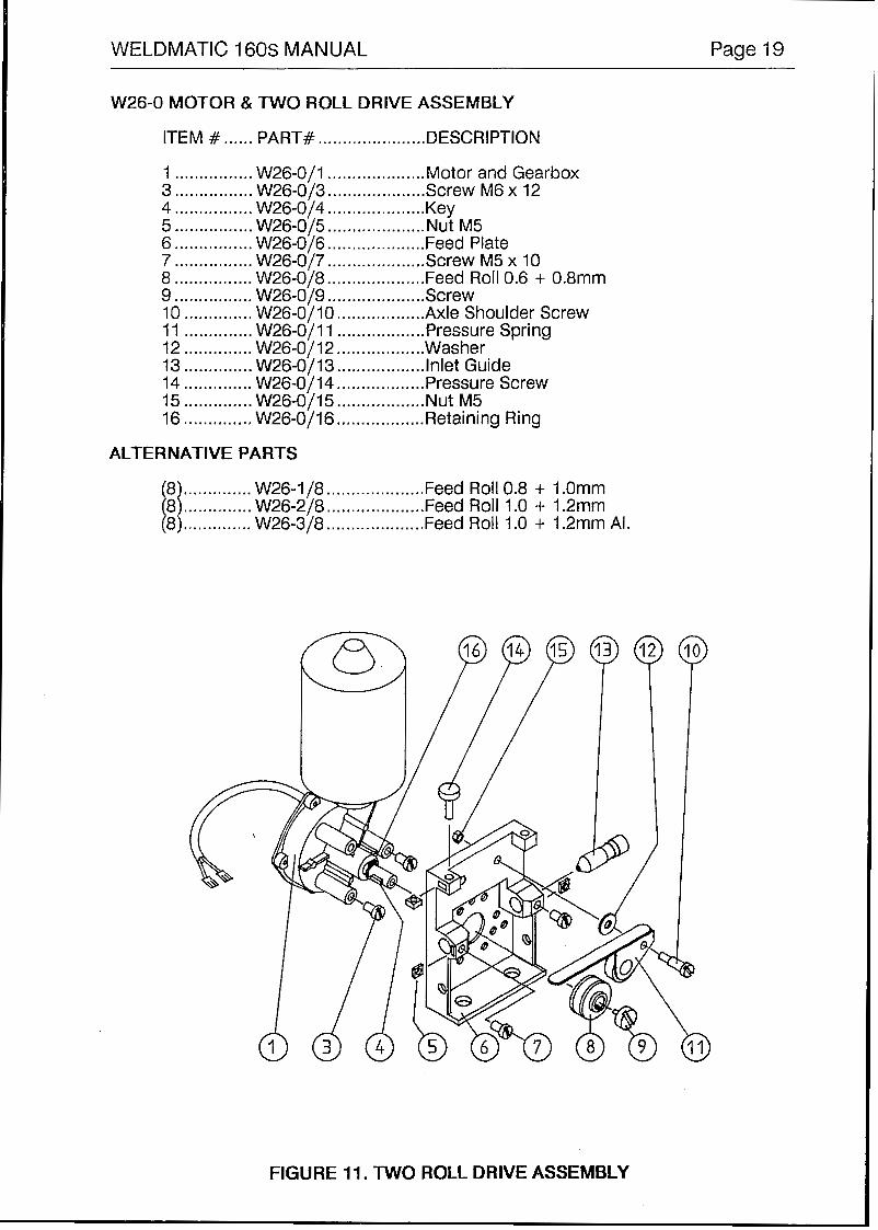
Fig.11 ........................ Wire Drive Assembly .......................... P . 19
Page 4 WELDMATIC 160s MANUAL
The information contained in this manual is set out to enable you to properly maintain your new equipment and ensure that you obtain maximum operating efficiency.
Please ensure that this information is kept in a safe place for ready reference when required at any future time.
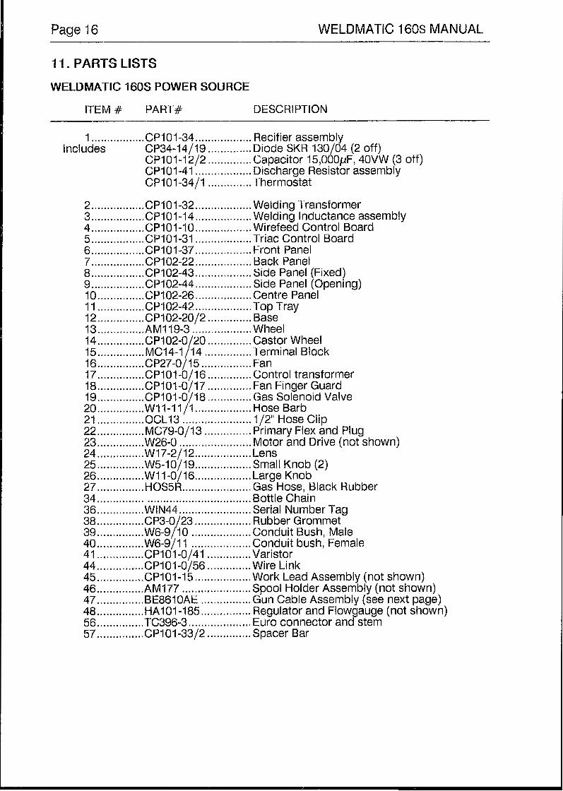
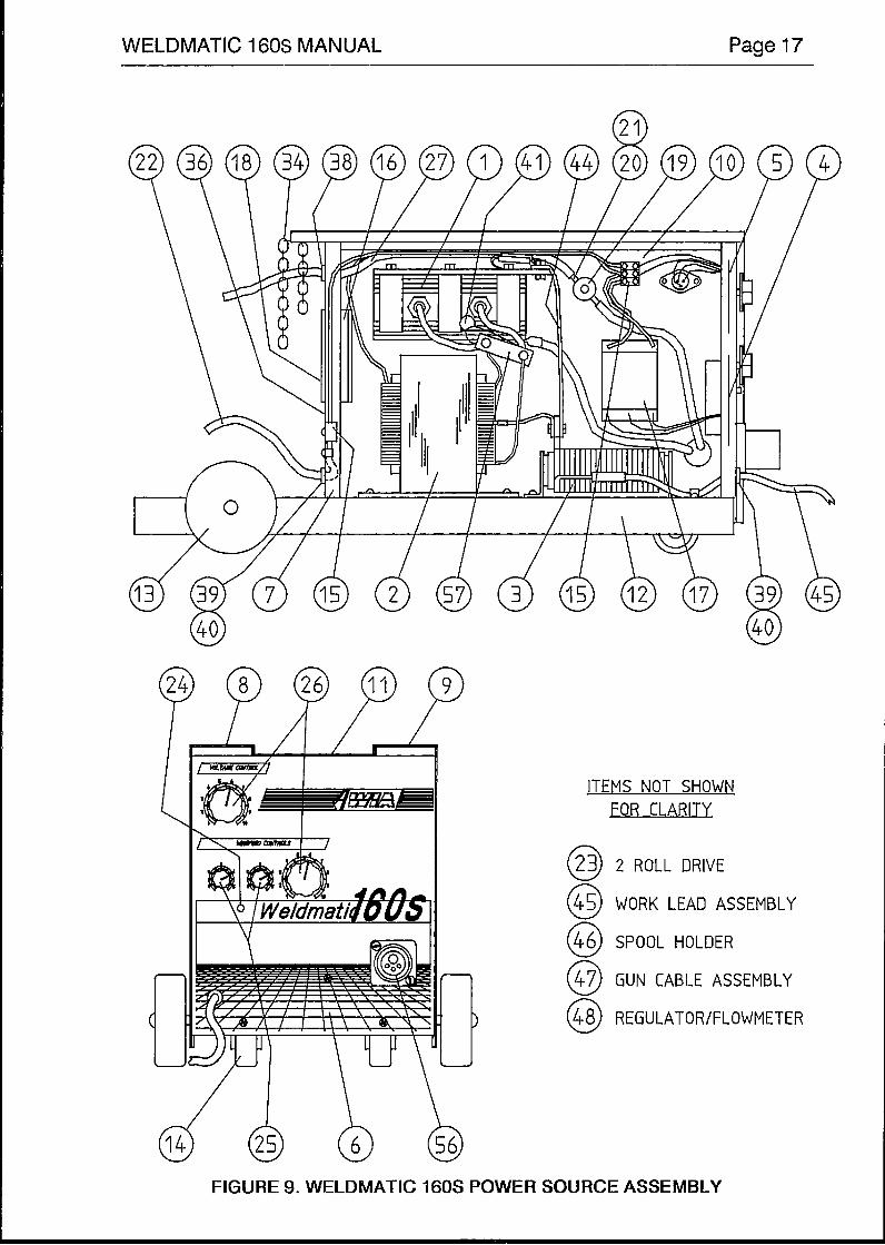
When requesting spare parts, please quote the model and serial number of the machine and part number of the item required. All relevant numbers are shown in lists contained in this manual. Failure to supply this information may result in unnecessary delays in supplying the correct parts.
1 .INTRODUCTION
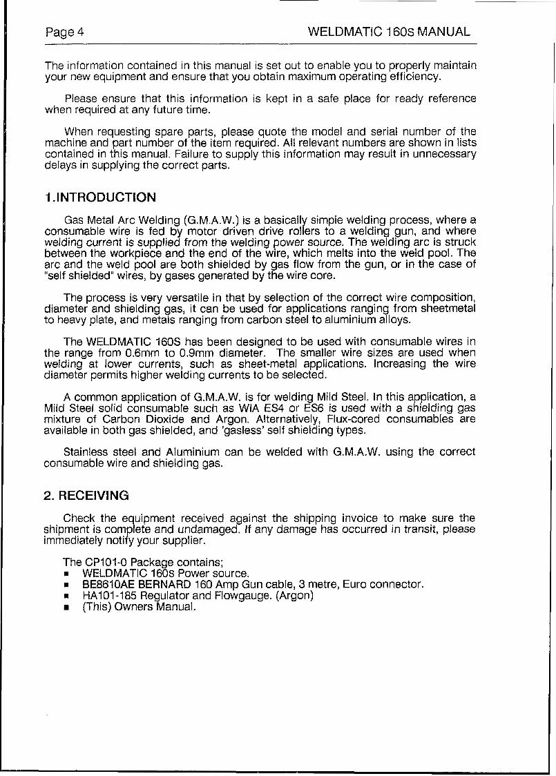
Gas Metal Arc Welding (G.M.A.W.) is a basically simple welding process, where a consumable wire is fed by motor driven drive rollers to a welding gun, and where welding current is supplied from the welding power source. The welding arc is struck between the workpiece and the end of the wire, which melts into the weld pool. The arc and the weld pool are both shielded by gas flow from the gun, or in the case of "self shielded" wires, by gases generated by the wire core.
The process is very versatile in that by selection of the correct wire composition, diameter and shielding gas, it can be used for applications ranging from sheetmetal to heavy plate, and metals ranging from carbon steel to aluminium alloys.
The WELDMATIC 160s has been designed to be used with consumable wires in the range from 0.6mm to 0.9mrn diameter. The smaller wire sizes are used when welding at lower currents, such as sheet-metal applications. Increasing the wire diameter permits higher welding currents to be selected.
A common application of G.M.A.W. is for welding Mild Steel. In this application, a Mild Steel solid consumable such as WIA ES4 or ES6 is used with a shielding gas mixture of Carbon Dioxide and Argon. Alternatively, Flux-cored consumables are available in both gas shielded, and 'gasless' self shielding types.
Stainless steel and Aluminium can be welded with G.M.A.W. using the correct consumable wire and shielding gas.
2. RECEIVING
Check the equipment received against the shipping invoice to make sure the shipment is complete and undamaged. If any damage has occurred in transit, please immediately notify your supplier.
The CP101-0 Package contains; I WELDMATIC 160s Power source. B BE8610AE BERNARD 160 Amp Gun cable, 3 metre, Euro connector I HA101485 Regutator and Flowgauge. (Argon)
(Thjs) Owners Manual.
WELDMATIC 160s MANUAL Page 5
3. SPECIFICATIONS
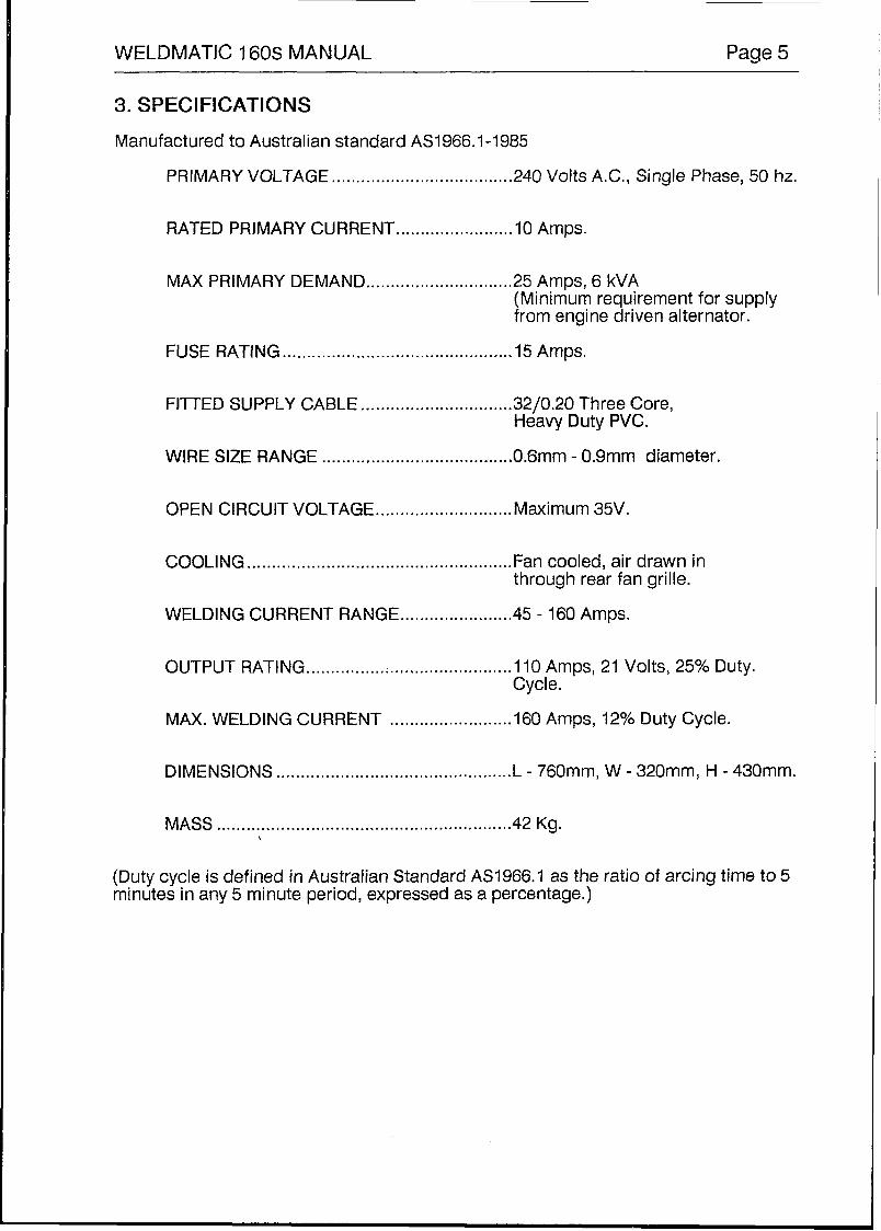
Manufactured to Australian standard AS1966.1-l985
PRIMARY VOLTAGE ..................................... 240 Volts A.C., Single Phase, 50 hz.
RATED PRIMARY CURRENT ........................ IO Amps.
MAX PRIMARY DEMAND .............................. 25 Amps, 6 kVA (Minimum requirement for supply from engine driven alternator.
MAX. WELDING CURRENT ......................... 160 Amps, 12% Duty Cycle.
Cy cl e.
DIMENSIONS ................................................ L - 760mm, W - 320mm, H - 430mm.
MASS .......................................................... ..42 Kg. ,
(Duty cycle is defined in Australian Standard AS1966.1 as the ratio of arcing time to 5 minutes in any 5 minute period, expressed as a percentage.)
Page 6 WELDMATIC 160s MANUAL
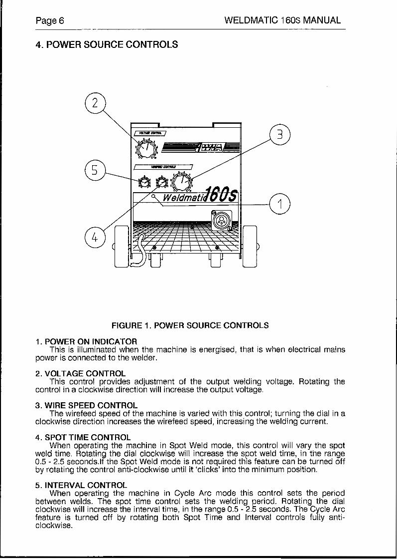
4. POWER SOURCE CONTROLS
FtGURE 1. POWER SOURCE CONTROLS
1 . POWER ON INDICATOR
power is connected to the welder. This is illuminated when the machine is energised, that is when electrical mains
2. VOLTAGE CONTROL
control in a clockwise direction will increase the output voltage. This control provides adjustment of the output welding voltage. Rotating the
3. WIRE SPEED CONTROL
clockwise direction increases the wirefeed speed, increasing the welding current. The wirefeed speed of the machine is varied with this control; turning the dial in a
4. SPOT TIME CONTROL When operating the machine in Spot Weld mode, this control will vary the spot
weld time. Rotating the dial clockwise will increase the spot weld time, in the range 0.5 - 2.5 seconds.lf the Spot Weld mode is not required this feature can be turned off by rotating the control anti-clockwise until it ‘clicks’ into the minimum position.
5 . INTERVAL CONTROL When operating the machine in Cycle Arc mode this control sets the period
between welds. The spot time control sets the welding period. Rotating the dial clockwise will increase the interval time, in the range 0.5 - 2.5 seconds. The Cycle Arc feature is turned off by rotating both Spot Time and Interval controls fully anti- clockwise.
WELDMATIC 160s MANUAL Page 7
5. INSTALLATION
CONNECTION TO ELECTRICAL MAINS POWER SUPPLY The WELDMATIC 160s is supplied with a 3 metre, 3 core Heavy Duty PVC mains
power supply cable and standard 10 Amp plug. Due to peak current requirements, the Electrical Mains supply to welding machines is best protected by fuses. Circuit Breakers may trip frequently if used in this application.
If it becomes necessary to replace the mains power supply cable, use only a cable
Access to the machine supply terminals is gained by removing the power-source
with an equivalent or higher current rating.
side panel opposite to the wire-spool enclosure.
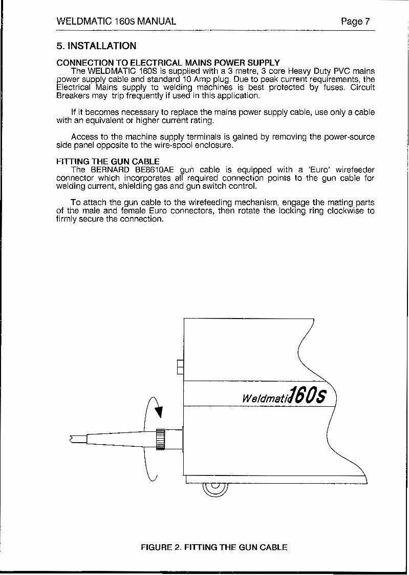
FllTlNG THE GUN CABLE The BERNARD BE8610AE gun cable is equipped with a ‘Euro’ wirefeeder
connector which incorporates all required Connection points to the gun cable for welding current, shielding gas and gun switch control.
To attach the gun cable to the wirefeeding mechanism, engage the mating parts of the male and female Euro connectors, then rotate the locking ring clockwise to firmly secure the connection.
FIGURE 2. FllTlNG THE GUN CABLE
Page 8 WELDMATIC 160s MANUAL
FtTrING THE GAS BOTTLE The MAXIMUM height of a gas cylinder to be fitted to the standard WELDMATIC
160s is 1 .O metre. The weight and high centre of gravity of taller cylinders will result in the machine becoming unstable. To enable use of taller cylinders, an optional accessory AM209 is available separately.
Depending on configuration of the cylinder to be used, the gas regulator / flowgauge may be fitted directly to the cylinder, or in conjunction with an elbow. DO NOT apply any grease to these joints, and tighten the nuts securely.
Fit the end of the gas inlet hose from the back panel of the machine to the connector supplied with the flow regulator, and secure with the clamp also supplied.
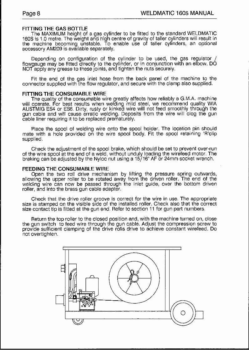
FITTING THE CONSUMABLE WIRE The quality of the consumable wire greatly affects how reliably a G.M.A. machine
will operate. For best results when welding mild steel, we recommend quality WIA AUSTMIG ES4 or ES6. Dirty, rusty or kinked wire will not feed smoothly through the gun cable and will cause erratic welding. Deposits from the wire will clog the gun cable liner requiring it to be replaced prematurely.
Place the spool of welding wire onto the spool holder. The location pin should mate with a hole provided on the wire spool body. Fit the spool retaining 'R'clip supplied.
Check the adjustment of the spool brake, which should be set to prevent over-run of the wire spool at the end of a weld, without unduly loading the wirefeed motor. The braking can be adjusted by the Nyloc nut using a 15/16" AF or 24mm socket wrench.
FEEDING THE CONSUMABLE WIRE Open the two roll drive mechanism by lifting the pressure spring outwards,
allowing the upper roller to be rotated away from the driven roller. The end of the welding wire can now be passed through the inlet guide, over the bottom driven roller, and into the brass gun cable adapter.
Check that the drive roller groove is correct for the wire in use. The appropriate size is stamped on the visible side of the installed roller. Check also that the correct size contact tip is fitted at the gun end. Refer to section 11 for gun part numbers.
Return the top roller to the closed position and, with the machine turned on, close the gun switch to feed wire through the gun cable. Adjust the compression screw to provide sufficient clamping of the drive rolls drive to achieve constant wirefeed. Do not overtighten.
WELDMATIC 160s MANUAL Page 9
6. NORMAL WELDING SEQUENCE
WELD START Closing the welding gun switch initiates this sequence of events:
H The Power Source contactor function is initiated. Welding voltage is applied
The wire drive motor is energised, wirefeed commences and the arc is
The gas valve is energised and gas flow commences;
between the work-piece and the consumable wire.
established.
WELD END Releasing the gun switch initiates this sequence of events:
H The wire drive motor is de-energised, and is dynamically braked to a stop; H After a short pre-set period, known as the ‘burn-back’ time, the Power-source
contactor function is released. This period ensures that the consumable wire does not ‘freeze’ in the weld poot. To adjust the ‘burn-back’ time, refer to Section IO.
H The gas valve is de-energised and the flow of shielding gas ceases.
NOTE that the welding gun should be held steady during the burn-back function at the completion of each weld. This will produce consistent wire stickout length.
7. BASIC WELDING INFORMATION
CHOICE OF SHIELDING GAS
used. The choice of shielding gas is largely determined by the consumable wire to be
For mild steel, many proprietary mixtures of argon and carbon dioxide are available. In general, the greater the percentage of carbon dioxide in a mixture, the greater the weld penetration into the parent metal, increasing to a maximum when 100% CO2 is used.
Conversely, the greater the percentage of argon in the mixture, the smoother will be the appearance of the weld, Typical CO2 content in available mixtures is in the range 5% to 25%.
Silicon Bronze and Aluminium must be operated in an inert atmosphere, usually Argon, however Argon + Helium mixtures may be used. The Helium content in such mixtures increases the ’heat’ of the arc, and therefore may be recommended when welding heavy sections. For Stainless steel, a mixture of Argon + Oxygen, or Argon + Carbon Dioxide + Helium is normally used.
Consult your gas supplier for more specific information.
SHIELDING GAS FLOW RATE In G.M.A.W., one of the functions of the shielding gas is to protect the molten
weld pool from the effects of oxygen in the atmosphere. Without this protection the weld deposit becomes ’honeycombed’ in appearance, an effect which is described as weld porosity.
In draft-free conditions the gas flow rate required to give adequate protection is typically 10 litres/min. in situations where drafts cannot be avoided, it may be necessary to increase this rate and/or to provide screening of the work area.
Weld porosity can also be caused by air entering the gas stream through a damaged hose, loose gas connection, or from restriction in the nozzle, such as from excess build-up of spatter.
Page 10 WELDMATIC 160s MANUAL
ESTABLISHING A WELD SElTlNG
the two variables that are adjusted in order to obtain a stable arc are; Once the consumable wire type, wire size and shielding gas have been chosen,
Wirefeed speed, m Welding arc voltage.
The wirefeed rate determines the welding current; increasing the feed rate increases the current, and decreasing it decreases current. The selected wirefeed rate must be matched with sufficient arc voltage; an increase of wirefeed rate requires an increase of arc voltage.
If the voltage is too low the wire will stub and stutter, and there will not be a steady arc. If the voltage is too high the arc will be long with the metal transfer within the arc occurring as a series of large droplets.
The welding current should be chosen to suit the thickness of the metal to be welded. It is important to check that the deposited weld provides sufficient strength to suit the application.
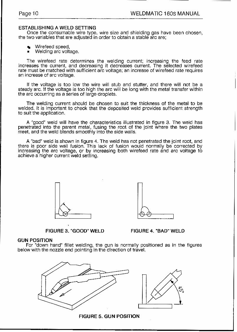
A "good" weld will have the characteristics illustrated in figure 3. The weld has penetrated into the parent metal, fusing the root of the joint where the two plates meet, and the weld blends smoothly into the side walls.
A "bad" weld is shown in figure 4. The weld has not penetrated the joint root, and there is poor side wall fusion. This lack of fusion would normally be corrected by increasing the arc voltage, or by increasing both wirefeed rate and arc voltage to achieve a higher current weld setting.
FIGURE 3. "GOOD" WELD FIGURE 4. "BAD" WELD
GUN POSITION
below with the nozzle end pointing in the direction of travel. For "down hand" fillet welding, the gun is normally positioned as in the figures
FiGURE 5. GUN POSITION
WELDMATIC 160s MANUAL Page 11
8. GENERAL MAINTENANCE
DUST Care should be taken to prevent excessive build-up of dust and dirt within the
welding power source. It is recommended that at regular intervals, according to the prevailing conditions, the machine covers be removed and any accumulated dust be removed by the use of dry, low pressure compressed air, or a vacuum cleaner.
WIREFEED In order to obtain the most satisfactory welding results from the G.M.A. welding
process, the wirefeed must be smooth and constant. It is therefore important to observe the following points;
D Keep the gun cable liner clear of dust and swarf build-up. When replacement becomes necessary, fit only the correct liner to suit the gun cable model. See Section 11. The build-up of dust in a cable liner can be minimized by regular purging of the liner with dry compressed air. This may be conveniently done each time the wire spool is replaced.
Replace the welding tip as it becomes worn.
D Keep the wire drive mechanism clean. Periodically check the drive rollers for wear and for free rotation.
D Check that the consumable wire spool holder rotates smoothly and that the braking action is not excessive. This also may be conveniently done each time the wire is replenished.
9. TROUBLE SHOOTING
UNSATISFACTORY RESULTS
m
D
I
WELD m
m
WIREFEED Erratic wirefeed is the MOST LIKELY cause of failure in all Gas Metal Arc Welding. It should therefore be the first point checked when problems occur. Refer to the section above.
Check for correct gas flow rate at the welding torch nozzle and ensure there are no gas leaks. The gun nozzle must be free from spatter and firmly attached to the welding gun to ensure that air is not drawn into the shielded area.
Check that the shielding gas selected is correct for the consumable wire in use.
1ING CIRCUIT Ensure that the work clamp is securely tightened onto the work-piece so that good electrical contact is achieved. Check also that the output polarity selected is appropriate for the consumable in use.
Surface contamination of the work-piece by water, oil, grease, galvanizing, paint, or oxide layers can severely disturb the welding arc resulting in a poor weld. Should this condition occur, surface cleaning of the work piece will be beneficial.
Page 12 WELDMATIC 160s MANUAL
WIREFEED / ARC VOLTAGE RELATIONSHIP If the consumable wire is stubbing into the workpiece, and a steady arc cannot be
obtained, it is likely that the arc voltage is set too low to suit the wire speed. To correct this situation either increase arc voltage, or decrease the wire speed.
If the arc length is too long, the arc voltage is too high to suit the wire speed. To correct this, increase wire speed or decrease arc voltage.
NO WELDING CURRENT
that the fan is running and the indicator light is illuminated. Check that Mains Supply is available at the WELOMATIC 160s Power Source, i.e.
Check continuity of the welding current circuit, i.e., work lead, work clamp and gun cable connections.
The WELDMATIC 160s welding power source is protected against overload by an inbuilt over-temperature thermostat.
In the event of an overlopad condition, the machine will not deliver welding current until it has cooled sufficiently. The thermostat will reset automatically - do not switch the machine off as the cooling fan will assist the resetting of the thermostat.
If the forgoing checks have been made and have not revealed the fault condition, a QUALIFIED SERVICE person should be consulted.
10. SERVICE INFORMATION.
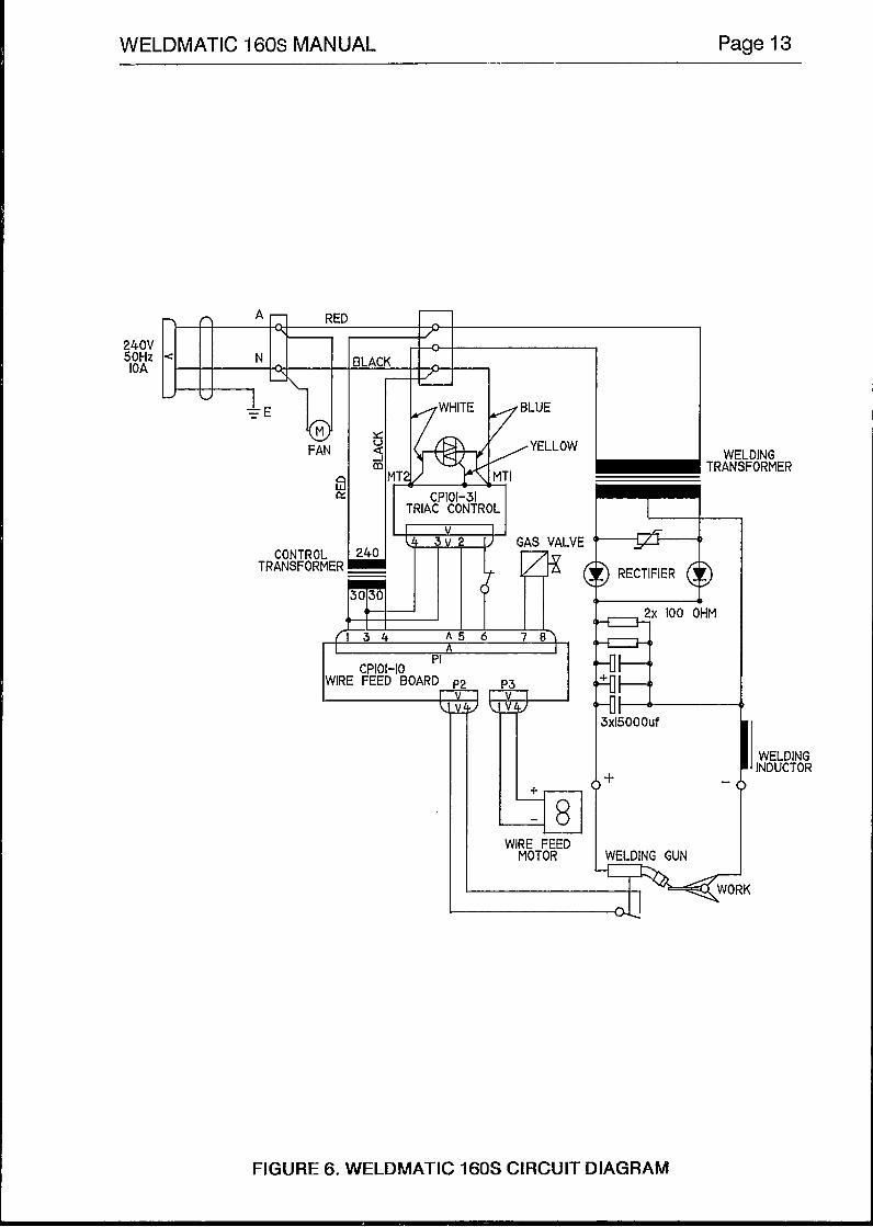
The main electrical components of the WELDMATIC 160s are listed below, with
Welding Rectifier Assembly, Item 1. This comprises two high-current rectifier diodes mounted on an aluminium heatsink, electrolytic filter capacitors, transient protection network and discharge resistors. Open circuit voltage = 34 V dc, with the maximum voltage setting selected.
Maximum open circuit secondary voltage = 24 - 0 - 24 V ac with the maximum voltage setting selected.
reference to the following circuit diagram.
Welding Transformer, Item 2. The Secondary winding is centre-tapped.
= Wirefeed control Board, Item 4. See following description.
Triac Control Board (including Triac), Item 5. See following description.
H Control Transformer, Item 17. The secondary winding is centre-tapped, providing an output voltage = 30 - 0 - 30 V ac.
Welding Inductance, Item 3.
Gas solenoid valve, Item 19.
WELDMATIC 160s MANUAL Page 13
TRIAC CONTROL
WIRE FEED BOARD
!
WIRE FEED MOTOR
t
j> RECTIFIER @
4 3X15000Uf
1 b
I
,+ -
WELDING GUN
I WELDING INDUCTOR
FtGURE 6. WELDMATIC 160s CIRCUIT DIAGRAM
Page 14 WELDMATIC 160s MANUAL
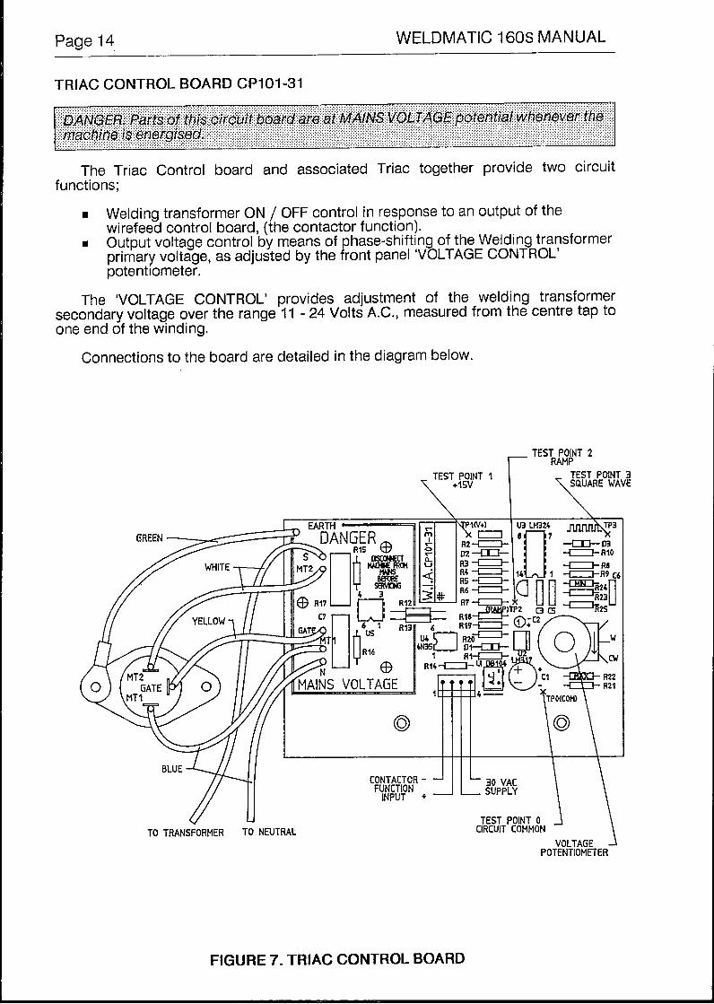
TRIAC CONTROL BOARD CP101-31
The Triac Control board and associated Triac together provide two circuit
Welding transformer ON / OFF control in response to an output of the wirefeed control board, (the contactor function).
m Output voltage control by means of phase-shifting of the Welding transformer primary voltage, as adjusted by the front panel ‘VOLTAGE CONTROL’ potentiometer.
functions;
The ‘VOLTAGE CONTROL’ provides adjustment of the welding transformer secondary voltage over the range 11 - 24 Volts A.C., measured from the centre tap to one end of the winding.
Connections to the board are detailed in the diagram below.
TEST POINT 2 RAMP
POTENTtOMETER VOLTAGE -I\
FIGURE 7. TRIAC CONTROL BOARD
WELDMATIC 160s MANUAL Page 15
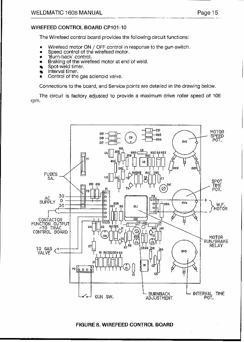
WIREFEED CONTROL BOARD CP101-10
The Wirefeed control board provides the following circuit functions:
= Wirefeed motor ON / OFF control in response to the gun-switch. m Speed control of the wirefeed motor. m 'Burn-back' control. m Braking of the wirefeed motor at end of weld.
Spot-weld timer. Interval timer. Control of the gas solenoid valve.
Connections to the board, and Service points are detailed in the drawing below.
The circuit is factory adjusted to provide a maximum drive roller speed of 106 rpm.
FUSES 5A. -< AC 30 -
SUPPLY * - 30 -
CONTACTOR FUNCTION OUTPUl
-TO TRIAC CONTROL BOARD
TO GAS +- VALVE <--
MOTOR SPEED POT. Dl8
DV -"-
L'J GUN SW. BURNBACK L INTERVAL TIME ADJUSTMENT POT.
To replace liner: release Euro connection, remove nozzle (l) and head (2). Withdraw old liner from the gun end. Feed new liner in also from the gun end. Refit the Euro connection. At the gun end compress the liner within the gun cable, then cut it one contact tip length past the end of the body tube (4). Refit head, tip and nozzle.
r I I I l I I """"""-
FIGURE I O . BE8610AE (160 AMP) GUN CABLE ASSEMBLY
(8) .............. W26-1/8 .................... Feed Roll 0.8 + 1 .Omm
(8). ............. W26-3/8 .................... Feed Roll 1.0 f 1.2mm AI. (8) .............. W26-2/8 .................... Feed Roll 1 .O -+ 1.2mm
FIGURE 11. TWO ROLL DRIVE ASSEMBLY
Page 20 WELDMATIC 160s MANUAL
12. SAFE PRACTICES IN USING WELDING EQUIPMENT
These notes are provided in the interests of improving operator safety. They should be considered only as a basic guide to Safe Working Habits. A full list of Standards pertaining to industry is available from the Standards Association of Australia, also various State Electricity Authorities, Departments of Labour and Industry or Mines Department and other Local Health or Safety Inspection Authorities may have additional requirements. WTIA Technical Note TN7-98 also provides a comprehensive guide to safe practices in welding.
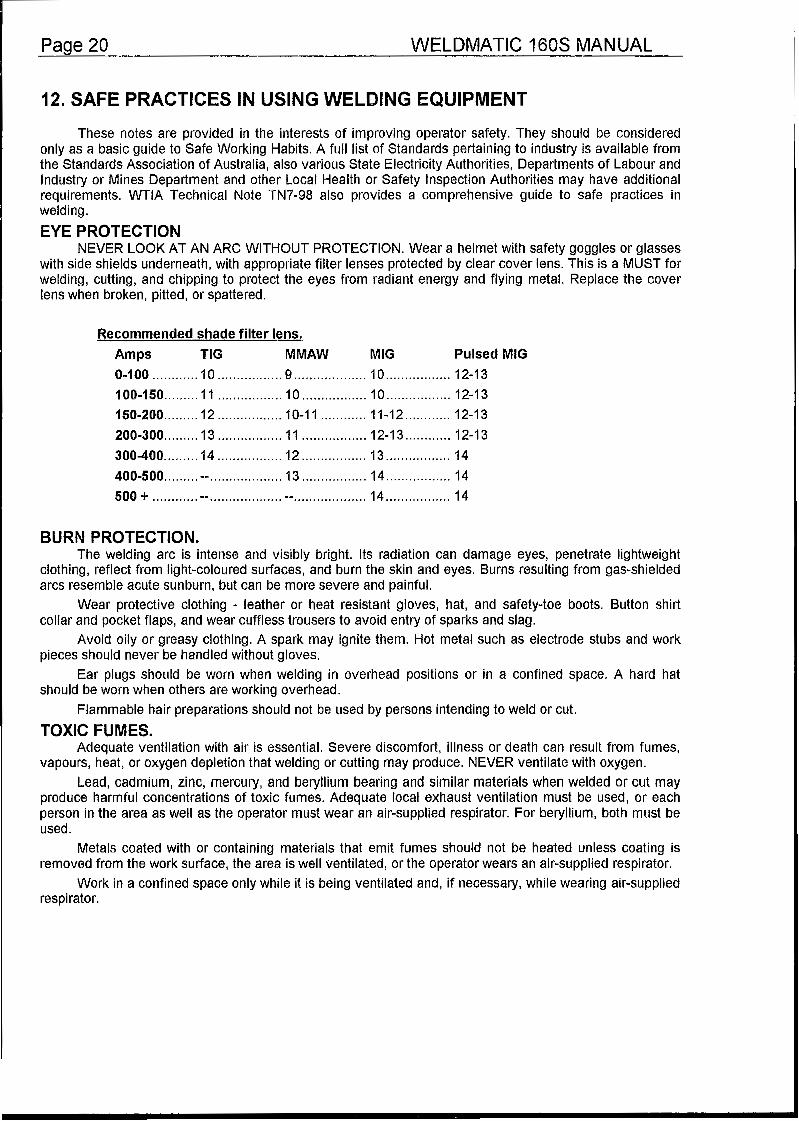
EYE PROTECTION NEVER LOOK AT AN ARC WITHOUT PROTECTION. Wear a helmet with safety goggles or glasses
with side shields underneath, with appropriate filter lenses protected by clear cover lens. This is a MUST for welding, cutting, and chipping to protect the eyes from radiant energy and flying metal. Replace the cover lens when broken, pitted, or spattered.
BURN PROTECTION. The welding arc is intense and visibly bright. Its radiation can damage eyes, penetrate lightweight
clothing, reflect from light-coloured surfaces, and burn the skin and eyes. Burns resulting from gas-shielded arcs resemble acute sunburn, but can be more severe and painful.
Wear protective clothing - leather or heat resistant gloves, hat, and safety-toe boots. Button shirt collar and pocket flaps, and wear cuffless trousers to avoid entry of sparks and slag.
Avoid oily or greasy clothing. A spark may ignite them. Hot metal such as electrode stubs and work pieces should never be handled without gloves.
Ear plugs should be worn when welding in overhead positions or in a confined space. A hard hat should be worn when others are working overhead.
Flammable hair preparations should not be used by persons intending to weld or cut.
TOXIC FUMES. Adequate ventilation with air is essential. Severe discomfort, illness or death can result from fumes,
vapours, heat, or oxygen depletion that welding or cutting may produce. NEVER ventilate with oxygen. Lead, cadmium, zinc, mercury, and beryllium bearing and similar materials when welded or cut may
produce harmful concentrations of toxic fumes. Adequate local exhaust ventilation must be used, or each person in the area as well as the operator must wear an air-supplied respirator. For beryllium, both must be used.
Metals coated with or containing materials that emit fumes should not be heated unless coating is removed from the work surface, the area is well ventilated, or the operator wears an air-supplied respirator.
Work in a confined space only while it is being ventilated and, if necessary, while wearing air-supplied respirator.
WELDMATIC 160s MANUAL Page 21
Vapours from chlorinated solvents can be decomposed by the heat of the arc (or flame) to form PHOSGENE, a highly toxic gas, and lung and eye irritating products. The ultra-violet (radiant) energy of the arc can also decompose trichlorethylene and perchlorethylene vapors to form phosgene. Do not weld or cut where solvent vapors can be drawn into the welding or cutting atmosphere or where the radiant energy can penetrate to atmospheres containing even minute amounts of trichlorethylene or perchotorethylene.
FIRE AND EXPLOSION PREVENTION. Be aware that flying sparks or falling stag can pass through cracks, along pipes, through windows
or doors, and through wall or floor openings, out of sight of the operator. Sparks and slag can travel up to 10 metres from the arc.
Keep equipment clean and operable, free of oil, grease, and (in electrical parts) of metallic particles that can cause short circuits.
If combustibles are present in the work area, do NOT weld or cut. Move the work if practicable, to an area free of combustibles. Avoid paint spray rooms, dip tanks, storage areas, ventilators. If the work can not be moved, move combustibles at least 10 metres away out of reach of sparks and heat; or protect against ignition with suitable and snug-fitting fire-resistant covers or shields.
Walls touching combustibles on opposite sides should not be welded on or cut. Walls, ceilings, and floor near work should be protected by heat-resistant covers'or shields.
A person acting as Fire Watcher must be standing by with suitable fire extinguishing equipment during and for some time after welding or cutting if;
m Combustibles (including building construction) are within 10 metres.
n Combustibles are further than 10 metres but can be ignited by sparks.
I Openings (concealed or visible) in floors or walls within 10 metres may expose combustibles to sparks.
I Combustibles adjacent to walls, ceilings, roofs, or metal partitions can be ignited by radiant or conducted heat.
After work is done, check that area is free of sparks, glowing embers, and flames.
An tank or drum which has contained combustibles can produce flammable vapors when heated. Such a container must never be welded on or cut, unless it has first been cleaned as described in AS.1674-1974, the S.A.A. Cutting and Welding Safety Code. This includes a thorough steam or caustic cleaning (or a solvent or water washing, depending on the combustible's solubility), followed by purging and inerting dith nitrogen or carbon dioxide, and using protective equipment as recommended in AS.1674-1974. Water-filling just below working level may substitute for inerting.
Hollow castings or containers must be vented before welding or cutting. They can explode. Never weld or cut where the air may contain flammable dust, gas, or liquid vapours.
SHOCK PREVENTION. Exposed conductors or other bare metal in the welding circuit, or ungrounded electrically alive
equipment can fatally shock a person whose body becomes a conductor. Ensure that the machine is correctly connected and earthed. If unsure have machine installed by a qualified electrician. On mobile or portable equipment, regularly inspect condition of trailing power leads and connecting plugs. Repair or replace damaged leads.
Fully insulated electrode holders should be used. Do not use holders with protruding screws. Fully insulated lock-type connectors should be used to join welding cable lengths.
Terminals and other exposed parts of electrical units should have insulated knobs or covers secured before operation.