38
V=V 0 sin(ωt) V=V 0 cos(ωt) V=V 0 sin(ωt+φ) AC Circuit Theory Amplitude Phase
| Date post: | 31-Dec-2015 |
| Category: |
Documents |
| Upload: | mahamudul-hasan-turjo |
| View: | 32 times |
| Download: | 1 times |

V=V0sin(ωt)
V=V0cos(ωt)
V=V0sin(ωt+φ)
AC Circuit TheoryAmplitude
Phase

R
Apply AC current to a resistor…
I I=I0sin(ωt)
VR=IR=I0Rsin(ωt)
C
I ( )
( )
( )20
0
0C
tsinIC
1
tcosIC
1
dttsinIC
1
C
QV
π−ωω
=
ωω
−=
ω== ∫…capacitor…
Voltage lags current by π/2I
L( ) ( )
200L tsinLItcosLIdt
dILV π+ωω=ωω==
…and inductor
Voltage leads current by π/2
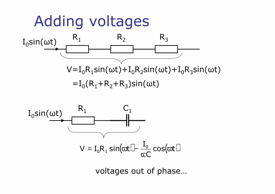
Adding voltagesR1 R2 R3I0sin(ωt)
V=I0R1sin(ωt)+I0R2sin(ωt)+I0R3sin(ωt)
=I0(R1+R2+R3)sin(ωt)
R1 C1I0sin(ωt)
( ) ( )tcosC
ItsinRIV 0
10 ωω
−ω=
voltages out of phase…
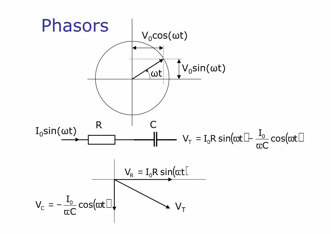
( )tsinRIV 0R ω=
( )tcosC
IV 0
C ωω
−= VT
Phasors
ωtV0sin(ωt)
V0cos(ωt)
R CI0sin(ωt) ( ) ( )tcos
C
ItsinRIV 0
0T ωω
−ω=
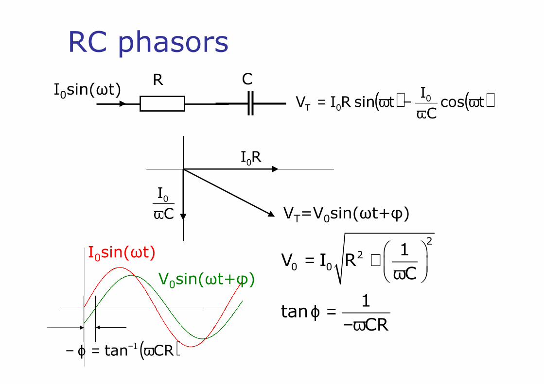
RC phasorsR C
I0sin(ωt) ( ) ( )tcosC
ItsinRIV 0
0T ωω
−ω=
RI0
C
I0ω VT=V0sin(ωt+φ)
= + ω
ϕ =−ω
2
20 0
1V I R
C
1tan
CR
I0sin(ωt)
V0sin(ωt+φ)
( )CRtan 1 ω=ϕ− −

Phasors – mathematics( ) ( )tcos
C
ItsinRIV 0
0T ωω
−ω=
VT=V0sin(ωt+φ)
= + ω
ϕ =−ω
2
20 0
1V I R
C
1tan
CRAsin(ωt) + Bcos(ωt) = Rsin(ωt + φ)
Rsin(ωt + φ) = Rsin(ωt)cos(φ) + Rcos(ωt)sin(φ)
A=Rcos(φ) B=Rsin(φ)
A2 + B2 = R2
B/A = tan(φ)

RL phasorsR L
I0sin(ωt)
( ) ( )tcosLItsinRIV 00T ωω+ω=
RI0
0LIωVT=V0sin(ωt+φ)
( )= + ω
ωϕ =
220 0V I R L
Ltan
R
I0sin(ωt)V0sin(ωt+φ)
ω=ϕ −
L
Rtan 1

RL filterR
LVIN VOUT
( )
( )2RL
RL
22IN
OUT
1
LR
1L
V
V
ω+
ω=
ω+ω=
0V
V 0
1V
V
IN
OUT
IN
OUT
→→ω
→∞→ω
high pass filter
RI0
0OUT LIV ω=( )22
00 LRIV ω+=
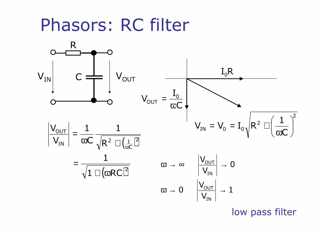
Phasors: RC filterR
CVIN VOUTRI0
C
IV 0
OUT ω=
2
200IN
C
1RIVV
ω+==
( )
( )2
2
C12
IN
OUT
RC1
1
R
1
C
1
V
V
ω+=
+ω=
ω
1V
V 0
0V
V
IN
OUT
IN
OUT
→→ω
→∞→ω
low pass filter

Bode plot
ω =0
1 R or
RC L
2
1
V
V
IN
OUT0 =ω=ω
(-3dB)
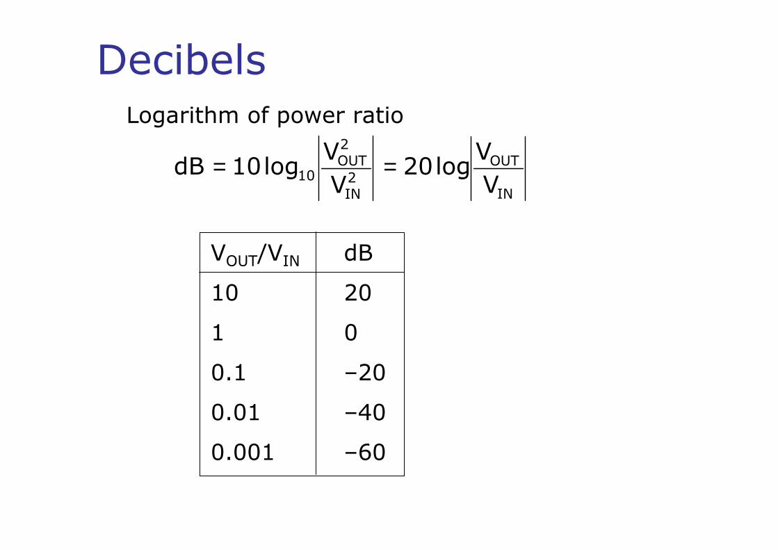
DecibelsLogarithm of power ratio
IN
OUT
2IN
2OUT
10V
Vlog20
V
Vlog10dB ==
VOUT/VIN dB
10 20
1 0
0.1 –20
0.01 –40
0.001 –60

Bode plot

Complex numbers in AC circuit theory
( ) ( ) ( )θ=+= jexpzzIm jzRez
Re(z)
Im(z)
θ j2=–1
|z|cos(θ)
|z|s
in(θ
)
( ) ( )
( ) ( )
=ω=
=ω=
ω
ω
tj
tj
eVtsinVtV
eVtcosVtV
00
00
Im
Re

Complex Impedance
ω
ω
ω
= =
= =ω
= = ω
∫
R 0
0C
L 0
j t
j t
j t
V IR I R e
1 IV Idt e
C j C
dIV L j I Le
dt
The ratio of the voltage across a component to the current through it when both are expressed in complex notation
RZR =
−= =ω ωC
1 jZ
j C C
LjZL ω=
I=I0sin(ωt) → I=I0ejωt

Complex Impedance
Real part: resistance (R)
Imaginary part: reactance
ω−ω
C
1L
( ) ( ) ( )IphaseZphaseVphase
IZV
IZV
+=
⋅=⋅=
jωL
Cj
1
ω
R
Ohm’s law

Series / parallel impedances
Z1=R Z2=jωL
Impedances in series: ZTotal=Z1+Z2+Z3…
= ∑T nn
Z Z
Z1 Z2 Z3
Impedances in parallel
=
= + +
∑
…
nT n
1 2 3
1 1
Z Z
1 1 1
Z Z Z
LR C
−=ω3
jZ
C

RC low pass filterR
CVIN VOUT
ZR
ZC
CR
CIN
ZZ
ZV
+
( )( )
( )
( )ϕ
ω+=
ω+ω−=
ω−ω−
ω+=
ω+=
+=
+=
ω
ω
jeRC1
1V
RC1
RCj1V
RCj1
RCj1
RCj1
1V
RCj1
1V
RV
ZZ
ZVV
2IN
2IN
IN
IN
Cj1
Cj1
IN
CR
CINOUT
( )RCtan 1 ω−=ϕ −

RL high pass filterR
LVIN VOUTLjR
LjVV INOUT ω+
ω=
( )ϕ
ω+
ω= je
1VV
2
RL
RL
INOUT
ω=ϕ −
L
Rtan 1

CP2 June 2003

this way up

this way up

LR C
I0ejωt
LRC series circuit
( )
IC
1LjR
IZZZ
VVVV
CLR
CLR
ω−ω+=
++=++=
2
2
C
1LRZ
ω−ω+=
−ω=ϕ ω−
R
Ltan C
11
Purely resistive at LC
1R =ω φ=0 Z=R
−ω+ω ω−
⋅
ω−ω+⋅=
R
Ltantj2
20
C1
1
eC
1LRIV

L
LRC parallel circuit
R C
I0ejωt
= + + =R L C
VI I I I
Z
ω−ω+=
L
1Cj
R
1
Z
1
= + ω − ω
+ − ω ω = + − ω ω
2 2
1Z
1 1j C
R L
1 1j C
R L
1 1C
R L
22
CL
1
R
1
1Z
ω−ω
+
=
ω−ω
=ϕ − CL
1Rtan 1

Bandpass filter
R
CVIN VOUT
L
IN
LC
LCOUT V
ZR
ZV
+=
CjLj
1
Z
1
LC
ω+ω
=
( )C
1jZ
L1LC ω−
=ω
( )
( )IN
L1
L1
OUT V
C
jR
C
j
V
ω−+
ω−=
ω
ω
( )2L12
IN
OUT
CR1
1
V
V
ω−+=
ω
1V
V
LC
1
0V
V 0 0
V
V
IN
OUT0
IN
OUT
IN
OUT
==ω=ω
→→ω→∞→ω
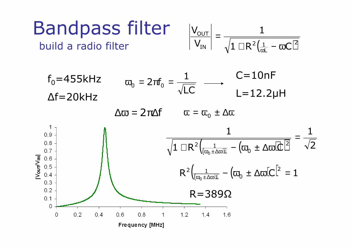
Bandpass filter( )2
L12
IN
OUT
CR1
1
V
V
ω−+=
ωbuild a radio filter
f0=455kHz
∆f=20kHzLC
1f2 00 =π=ω
ω∆±ω=ω 0
C=10nF
L=12.2µH
( ) ( )( ) 2
1
CR1
12
0L12
0
=ω∆±ω−+ ω∆±ω
( ) ( )( ) 1CR2
0L12
0=ω∆±ω−ω∆±ω
R=389Ω
∆ω = π∆2 f
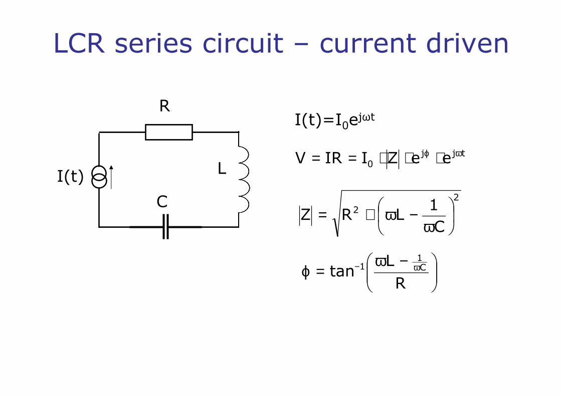
I(t)=I0ejωt
LCR series circuit – current driven
2
2
C
1LRZ
ω−ω+=
−ω=ϕ ω−
R
Ltan C
11
tjj0 eeZIIRV ωϕ ⋅⋅⋅==
L
R
C
I(t)

L
R
C
V(t)=V0ejωt
LCR series circuit – voltage driven
2
2
C
1LRZ
ω−ω+=
−ω=ϕ ω−
R
Ltan C
11
ϕ−== j0 eZ
V
Z
VI
V(t)
ω → ∞ →
ω → →
ω → ω = 00
I 0
0 I 0
V I maximum
R
2
2
0
C
1LR
VI
ω−ω+
=

R/L=106
R/L=105

this way up

LC circuit – power dissipation
Power is only dissipated in the resistor
proof – power dissipated inductor and capacitor –none
( ) ( )∫=T
0dttVtI
T
1P ω
π= 2T
( ) ( )( )
( )( )tcosXIV
tcosLIV
tcosIC
1V
tsinItI
0X
0L
0C
0
ω=ωω=
ωω
−=
ω=
Lor C
1X ω
ω−=
reactance
( ) ( ) ( ) 0tsinXIT2
1dttcostsinXI
T
1P
/2T
0
220
T
00C,L
=
ωω
=ωω=ωπ=
∫
L
R
CI(t)

LRC Power dissipation
L
R
C
V(t) Z=Z0ejφ
I
V(t)=
ω−ω+=
C
1LjRZ
2
20
C
1LRZ
ω−ω+=
( )R
Ltan C
1ω−ω
=ϕ
( ) ( )( ) ( )ϕ−ω=
ω=
tsinZ
VtI
tsinVtV
0
0
0
( ) ( ) ( ) ( ) ( )ϕ−ωω== tsintsinZ
VtItVtP
0
20
Instantaneous power

Power dissipation
( ) ( ) ( ) ( ) ( )ϕ−ωω== tsintsinZ
VtItVtP
0
20
( ) ( ) ( ) ( ) ( )[ ]ϕω−ϕωω= sintcoscostsintsinIV 00
( ) ( ) ( ) ( ) ( )[ ]dtsintcostsincostsinIVT
1P
T
0
200∫ ϕωω−ϕω=
( )( ) ( ) 0 dtcost2cos1T
IVP
T
0 2100 −ϕω−= ∫
T
0
00 cos2
t
T
IV
ϕ=
ϕ= cos2
IV 00 ϕ= cosIV RMSRMS
cosφ = power factor

Power factor
RMSRMSIV
P
power apparent
power averagecos ==ϕ
Resistive load Z=R cosφ=1
Reactive load Z=X cosφ=0

Bridge circuits
V(t) V
Z1 Z3
Z2Z4
To determine an unknown impedance
Bridge balanced when VA−VB=0
VA VB
( ) ( )− =+ +2 4
1 2 3 4
Z ZV t V t 0
Z Z Z Z( ) ( )
=+ +
+ = +
=
2 4
1 2 3 4
2 3 4 4 1 2
2 3 4 1
Z Z
Z Z Z Z
Z Z Z Z Z Z
Z Z Z Z

CP2 September 2003

this way up

this way up

this way up


