CP40 Installation Manual Revision 1.4 Cansec Systems Ltd. October 2006 This manual is based on the latest information available to Cansec Systems Ltd. At the time of this document being printed. Technical support is available to authorized Cansec dealers by calling 905-820-2404 or via email at [email protected]. Cansec Systems Ltd. 3105 Unity Drive, Unit #9, Mississauga, Ontario, Canada Tel: (905) 820-2404, Fax:(905) 820-0301, http://www.cansec.com
Transcript
CP40 Installation Manual
Revision 1.4
Cansec Systems Ltd. October 2006
This manual is based on the latest information available to Cansec Systems Ltd. At the time of
this document being printed. Technical support is available to authorized Cansec dealers by
5470 to Door Contact: ...............................................................................1 Pair, 22 AWG
Loop Wire: ................................................................................single core, 16 or 18 AWG
Input/Output Point Wiring: .......................................................... 22 AWG wire to a maximum of 2,000 ft.
CP40 Installation Manual Hardware Overview
Cansec Systems Ltd. 1-8
Figure 2: CP40 Board Layout
OPTION DIP SWITCH
CP40 Installation Manual Installation
Cansec Systems Ltd. 2-1
2. Installation
This section provides complete installation instructions for installing and configuring CP40 Access Control
Panels in RS-485 Multi-Drop, RS-422 Multi-Drop, and RS-422 Daisy-Chain configurations. Both RS-422
methods would primarily be used to “add-on” to existing CP30 installations.
2.1 Unpacking
The CP40 enclosure will contain a cardboard cutout that holds the CP40 circuit board securely for shipping.
An auxiliary board and a power supply may also be secured in the cutout if ordered. Also, a plastic bag
containing all screws and connectors will be attached to the cutout.
2.2 Mounting the CP40
The CP40 should be mounted in a secured area with consideration given to the maximum cable lengths to
the readers and for communications.
1. Drill two holes corresponding to the top two mounting holes as shown in Figure 3.
2. Insert #8 screws half way into the holes. Use anchors if necessary.
3. Hang the CP40 cabinet on the two screws, and then tighten them.
4. Drill the bottom two holes and secure the cabinet with two screws.
5. After ensuring that you are properly grounded, remove the CP40 circuit board from the anti-static
bag. Align the mounting holes on the CP40 with the mounting studs on the cabinet and fasten with
the screws provided.
6. Plug the cabinet LED connector into JP40 as shown in Figure 4.
CAUTION: BEFORE REMOVING CIRCUIT BOARDS FROM THEIR ANTI-STATIC BAGS,
ALWAYS TOUCH AN EARTH GROUND TO REMOVE THE ELECTROSTATIC
CHARGE FROM YOUR BODY. IT IS HIGHLY RECOMMENDED THAT WHEN
HANDLING ANY CIRCUIT BOARDS CONTAINING CMOS DEVICES, STATIC
STRAPS SHOULD BE WORN AND CONNECTED PROPERLY TO EARTH GROUND.
CP40 Installation Manual Installation
Cansec Systems Ltd. 2-2
Figure 3: Mounting the CP40 Cabinet
Figure 4: Cabinet LED Connector
CP40 Installation Manual Installation
Cansec Systems Ltd. 2-3
2.3 Connecting the Cabinet Tamper Switch
Each CP40 cabinet is equipped with a tamper switch located at the top right corner of the cabinet. Cut the
wire loop connected to the switch and connect the two ends to the Cabinet Tamper Input as shown in Figure
5. This is a Normally Closed input and must be enabled as shown.
Figure 5: Cabinet Tamper
2.4 Installing an Input/Output Board (SIOPT-16) 1. Remove the Input/Output board from the anti-static bag. With the power to the CP40
disconnected, connect the I/O board ribbon cable and power cable as shown in Figure 6.
2. Snap the supplied plastic stand-offs into the mounting holes on the CP40. Then align the mounting
holes on the Input/Output board and push down to snap the board into place.
3. Enable the I/O board via the CP40 Option Dip Switch. See Section 2.24 for location of Option
Dip Switch.
Note: For changes to the Option Dip Switch to take effect, a RESET must be performed by either pressing
the RESET switch or by powering up the unit.
CP40 Installation Manual Installation
Cansec Systems Ltd. 2-4
Figure 6: Mounting the Input/Output board
2.4.1 Configuring the Input/Output Board (SIOPT-16)
The SIOPT-16 points can be configured via jumpers as either Supervised Inputs or dry contact relay Outputs.
The supervised Inputs require that a Cansec end-of-line resistor pack be connected with a NORMALLY
CLOSED contact at the end of the line. See Figure 7 for the board layout and jumper settings. See sections
2.4.2 and 2.4.3 for point wiring.
2.4.2 Input Point Wiring
All Input points must use Cansec end-of-line resistor pack as shown in Figure 8.
2.4.3 Output Point Wiring
Output points are dry contact relay outputs that may be configured as NORMALLY OPEN or NORMALLY
CLOSED. To operate any device in which has an inductive load (coil) that is powered from a DC source,
you must install a 1N4001 or 1N4002 series diode (or equivalent) in parallel across the coil terminals as
shown in Figure 9. Output relays are rated at: 2A, 30VDC.
Note: If you do not connect a diode as described, you will have erratic operation and will eventually
damage the unit. Switching of 110VAC is not recommended for safety reasons. Another
relay should be used to isolate the AC from the unit.
CP40 Installation Manual Installation
Cansec Systems Ltd. 2-5
Figure 7: Input/Output Board Layout
(Fire Alarm Input not UL or ULC Rated)
Figure 8: Input Point Wiring
CP40 Installation Manual Installation
Cansec Systems Ltd. 2-6
Figure 9: Output Point Wiring
2.4.4 Input/Output Board Fire Alarm Release (I/O Board Fire Alarm Release not UL or ULC listed)
The 12VDC relay power on the I/O board can be controlled in conjunction with the CP40 or can be
controlled solely through the SIOPT-16 Fire Alarm Release Input, JP6.
To control the I/O Board’s Fire Alarm Release through the CP40's Fire Alarm Release Input, set the
jumper on the CP40 labeled “I/O FAR” (JP56) to “ON”. This jumper is located to the left of the “Reader B”
fuse (see Figure 10). Keep the Fire Alarm Release on the I/O Board (JP6) shorted. When the Fire Alarm
Release is “opened” on the CP40, the 12VDC will be removed from the I/O board and the output states will
change to the opposite of their normally open or closed jumper settings.
To control the I/O Board’s Fire Alarm Release Separately from the CP40's Fire Alarm Release, set the
jumper on the CP40 labeled “I/O FAR” (JP56) to “OFF”. This jumper is located to the left of the “Reader
B” fuse (see Figure 10). Keep the Fire Alarm Release on the I/O Board (JP6) closed or control the Normally
Closed Input (JP6) from another device. When JP6 on the I/O Board is “opened”, the 12VDC will be
removed from the I/O board and the output states will change to the opposite of their normally open or
closed jumper settings.
CP40 Installation Manual Installation
Cansec Systems Ltd. 2-7
Figure 10: I/O Board Fire Alarm Release (I/O Board Fire Alarm Release not UL or ULC listed)
2.5 Elevator Control Systems
Elevator Control Systems are available in 16, 32, 48, and 64 floor configurations. One (1) Elevator Control
System is required for each elevator cab with one (1) reader port available for use inside the elevator. Dry
contact relay outputs are provided from the Elevator System to interface with the elevator manufacturers
system. The second reader port on the CP40 (Reader “B”) may only be used as a “Lobby Call-Down Reader”
that will activate its lock output when used by a cardholder with access to at least one (1) floor. The lock
output can then be used to initiate a call-down to the elevator manufacturer’s system. Programming and
transactions are not available for “Reader B” on an elevator configuration.
2.5.1 Elevator Configurations
If you are installing a 16 Floor Elevator Control System, the Elevator Control Board (SIOPT-16) must be
installed directly on top of the CP40 as per Figure 6 on page 2-4. If you are installing either a 32, 48, or 64
Floor System, the Elevator Control Systems are comprised of two (2) units. In this case the Elevator Boards
(SIOPT-16) are connected to an Interface board mounted in the 2nd
cabinet. The Interface board communicates
to an RS-422 (4 wire) communications port on the CP40 in the 1st cabinet. See Section 2.15 for communication
wiring. The Elevator Outputs should be configured as NORMALLY OPEN (See Figure 7, page 2-5).
To disable access control and activate all floor selection buttons in the elevator cab on Fire Alarm:
16 Floor Configuration: See section 2.4.4
32-64 Floor Configuration: connect JP6 (See Figure 7 on page 2-5) on each Elevator Control Board
(SIOPT-16) to the normally closed output of the Fire Alarm panel. When connecting the Fire Alarm Release
Inputs in parallel to the Fire Alarm Panel’s output, maintain polarity on JP6 of each SIOPT-16 board.
CP40 Installation Manual Installation
Cansec Systems Ltd. 2-8
Figure 11: Typical Elevator Configuration
Travel Cable: For Wiegand readers, use 5 to 7 conductor, #18 AWG, overall shield (max. 500 ft.)
Contact elevator manufacturer for installation of Travel Cable.
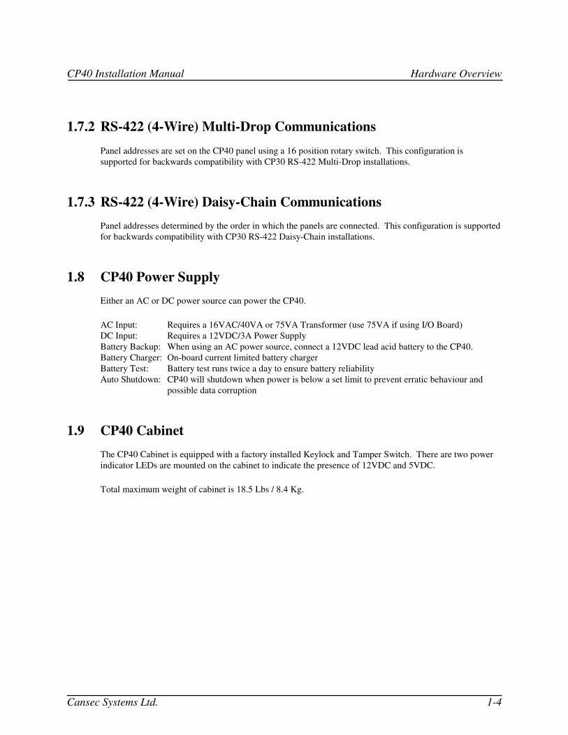
2.6 Connecting the Locking Devices
This output provides either a dry contact relay output, Normally Open or Normally Closed, or 12VDC @
400 mA maximum to the locking device for each reader. Since the 12VDC outputs are supplied through
on-board relays, Normally Open or Normally Closed connections are available to accommodate electric
strikes or magnetic locks. Lock output relays are rated at 8 Amp, 24VDC. See the following figures for
configuration and wiring.
Note: You must consult the local fire authorities before connecting any card readers or locking devices to
fire exit doors.
LED Indicators: Each Lock Output has an LED indicator (located next to the Lock Output terminal) that
turns ON to provide a visual indication that the lock output is activated. Reader “A”: LED7,
Reader “B”: LED15
CP40 Installation Manual Installation
Cansec Systems Ltd. 2-9
Figure 12: Connecting 12V Magnetic Locks, < 400 mA
Figure 13: Connecting Electric Strikes, >12V or 400 mA
CP40 Installation Manual Installation
Cansec Systems Ltd. 2-10
Figure 14: Connecting 12V Electric Strikes, <400 mA
Figure 15: Connecting Magnetic Locks, >12V or 400 mA
CP40 Installation Manual Installation
Cansec Systems Ltd. 2-11
2.7 Connecting Door Contacts and Exit Buttons
Door Contacts: To monitor Forced Entry or Door-Held-Open alarm conditions, connect NORMALLY
CLOSED door contacts to the door contact inputs. Door Contact inputs must be
“Enabled” via jumpers JP23 (Reader “A”) and JP52 (Reader “B”) as shown (see Figure
17) to monitor alarm conditions.
Exit Buttons: To activate a “Request-to-Exit” command that in turn activates the Lock Output and
Alarm Shunt Output, connect a NORMALLY OPEN MOMENTARY switch to each
exit button input. You must also enable exit button operation on each door by turning ON
switch positions 2 (Reader “A”) and 5 (Reader “B”) on switch S5 (see Figure 17).
If an exit button input is held in a closed state, only one “Request-to-Exit” command will
be initiated. This “one-shot” approach is implemented to prevent vandals from keeping
the Exit Button closed, therefore maintaining an unlocked state on the door.
Note: It is important to note that both the Door Contact and Exit Button Inputs are 12V pull-down
circuits. Only connect dry contact devices to these inputs. Failure to do so may cause erratic
operation and possibly damage the CP40.
Figure 16: Door Contact Wiring
CP40 Installation Manual Installation
Cansec Systems Ltd. 2-12
Figure 17: Enabling Door Contact and Exit Button Inputs
Figure 18: Exit Button Wiring
CP40 Installation Manual Installation
Cansec Systems Ltd. 2-13
2.8 Connecting Wiegand Compatible Readers
Wiring applies to all Wiegand compatible readers with a standard 26 bit or Cansec 37 bit format. Connect
and configure the readers as shown in Figure 20. For support of other custom Wiegand formats, contact
Cansec Systems Ltd.
Note: The number of conductors for Wiegand compatible readers depends on the reader and installation
requirements. At a minimum, four conductors are required for power and data. For LED control on Dual-
Line LED readers, two (2) additional conductors are required, whereas one (1) additional conductor is
required for Single-Line LED Readers. Another conductor may also be required for Sonalert control by the
CP40 for annunciation of Forced Entry and Door Held Open alarms as well as other audible indicators used
for Access Granted & Access Denied conditions.
Warning: The jumper settings for reader power are set to 12V by default. Check the documentation
that came with the reader before connecting to the CP40. Connecting a 5V reader to 12V will
damage the unit. All Cansec manufactured readers will operate at 12V.
Figure 20: Connecting Wiegand Compatible Readers
CP40 Installation Manual Installation
Cansec Systems Ltd. 2-14
Connecting Wiegand Compatible Readers (contd.)
When connecting certain types of Wiegand compatible readers, it may be necessary to read the data in
reverse. For example, the Sensor Wiegand Reader (Insert Version) reads the card data when removing the
card that then transmits the data in reverse to the host controller. In this case or with other readers that
transmit in a reverse direction, switch S5 must be set as shown in Figure 21.
Figure 21: Wiegand Reverse Switch Setting
2.9 Connecting the Fire Alarm Release and Reset Inputs (Fire Alarm Release and Reset not UL or ULC listed) Fire Alarm Release Input: Connect a normally closed dry contact output from a Fire Alarm Panel
so that power to the lock outputs will drop off in the event of a fire. To
ENABLE the Fire Alarm Release, move JP62 to pins 2-3 as shown in
Figure 22.
Fire Alarm Reset Input: When JP63 is ENABLED (Pins 2-3) and a Fire Alarm Release has
occurred, a momentary closure must be applied to the Fire Alarm Reset
Input to restore power to the lock outputs. When JP63 is DISABLED
(Pins 1-2) and a Fire Alarm Release has occurred, power to the lock
outputs will be returned once the Fire Alarm Release Input is closed.
See Figure 22.
Control of I/O Board: When JP56 is set to ON; the CP40 will control the I/O Board Fire Alarm
Release circuit. When JP56 is set to OFF, the I/O Board Fire Alarm
Release circuit is independently controlled via its own Fire Release
input. For CP40 control, the Fire Input on the I/O board must be
shorted.
CP40 Installation Manual Installation
Cansec Systems Ltd. 2-15
Figure 22: Enabling Fire Alarm Release and Reset
(Fire Alarm Release and Reset not UL or ULC listed)
2.10 Power Supply Inputs/Outputs and Battery Backup
Power Supply Inputs: The CP40 may be powered from either an AC or DC power source (not both).
AC Supply: Use a 16V, 40VA transformer connected to JP59.
DC Supply: Use a 12V, 3A supply connected to JP60 (Cansec PS123A Supply recommended)
Battery Charger: You may connect a 12V lead acid re-chargeable battery to the battery terminals provided.
Note: Only the AC input will charge the battery. If the DC input is used, the battery circuit does not
function, thus you will have to connect the battery to the DC supply (if battery backup is desired).
Caution: Watch polarity when connecting the battery to the CP40.
Battery Test: A battery test is performed at 10:00 am and 6:00 pm. During these times, the CP40 will run
from battery power for one (1) minute. If during this time the battery level drops below a preset value, a
message will be transmitted to the host PC (not supported in PassMaster and some versions of Maestro) host
software may) If you are connecting a battery to the CP40 (“To Battery” connectors), set JP46 to ON to
enable battery testing. If a battery is not connected to the CP40, set JP46 to OFF to disable battery testing,
otherwise the test will fail. See Figure 23 for location of JP46.
CP40 Installation Manual Installation
Cansec Systems Ltd. 2-16
Automatic Shutdown: When a battery is connected to the CP40 and a power failure occurs, the CP40 will
automatically shutdown when the battery voltage drops below 7.5V. This feature prevents data corruption
from occurring on the CP40 due to low voltage.
5VDC Auxiliary Output: JP58 provides 5VDC @ 300 mA maximum.
12VDC AKP100/200 Keypad Output: JP5 provides 12VDC for connecting the Cansec AKP100/200 series
keypads.
Figure 23: Power and Battery Connections
CP40 Installation Manual Installation
Cansec Systems Ltd. 2-17
2.11 Forced Entry, Door Held Open, Alarm Shunt Outputs
Each reader port on the CP40 is equipped with three relay outputs for Forced Entry, Door Held Open, and
Alarm Shunt. Each relay provides a dry contact, SPDT 2A @ 28VDC maximum. Door contacts must be
connected to the CP40 door contact input(s) and enabled to monitor for “forced entry” and “door held open”
alarm conditions. An LED is located near each output on the CP40.
Tamper/Forced Entry Output:
Forced Entry: If the door contact is forced open without either a valid “Access
Granted” or Exit Button transaction, a Forced Entry Alarm occurs and
this output will be activated. A message will also be transmitted to the
host if the panel is on-line.
Tamper: A reader tamper alarm can be created if pin 1 and pin 8 are shorted
together. Connect a NORMALLY OPEN switch in the back box of the
reader that shorts out pins 1 and 8 on the reader port. If someone pulls the
reader from the wall, the switch will close and activate this output.
Door Held Open Output: If a cardholder is granted access by either card or exit button usage and
the door is held open longer than the Door Held Open time programmed
from the host PC, a Door Held Open Alarm occurs and this output will be
activated. A message will also be transmitted to the host if the panel is
on-line.
Alarm Shunt Output: This output will activate when a user is granted access by using a card or
exit button. This output may be used to bypass external alarm points.
CP40 Installation Manual Installation
Cansec Systems Ltd. 2-18
2.12 Comm Fail Output
JP21 is a dry contact relay output that will activate when communications to the CP40 is lost. The main
function of this output is to provide a means of local annunciation. See Figure 24 for location of JP21.
2.13 Lithium Battery for Database and RTC JP25 controls the attachment of power from the on-board lithium battery to the database and real time clock
circuitry. The jumper is set to “OFF” by default for shipping and storage and should be set to “ON” after
installation to maintain the integrity of the database and real time clock. See Figure 24 for location of JP25.
Figure 24: Comm Fail Output & Lithium Battery Jumper
CP40 Installation Manual Installation
Cansec Systems Ltd. 2-19
2.14 Communications
Note: RS-485 (2-Wire) Multi-Drop Communications recommended for new installations.
The CP40 can be configured to communicate in either (2) two wire RS-485 or (4) wire RS-422 protocols
with up to (16) sixteen controllers on each communications trunk. The number of communication trunks
supported depends on the software package being used. See Section 2.15.1 to 2.15.3 for the various
communication configurations and wiring diagrams. See Figure 25 for location of communication
connectors, indicators, jumpers, and switches.
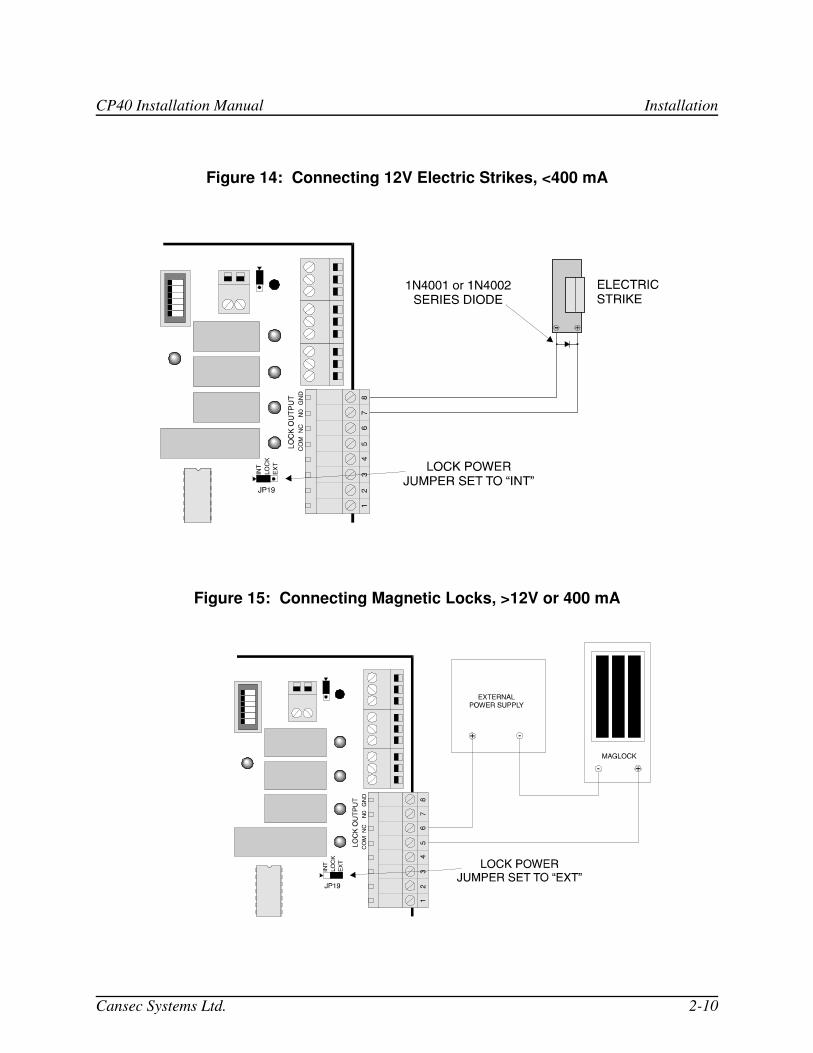
Figure 25: Location of Communication Jumpers, Switches, Connectors, LEDs
Communication LEDs: These are bi-coloured LEDs that will flash between RED and GREEN when
communications are active on the corresponding port. RED indicates that the panel is
receiving while GREEN indicates the panel is transmitting.
CH1 LED: This LED will indicate communications on CH1. This port is only used
for Daisy-Chain communications (CP30 mode only), or to 32-64 floor
elevator controllers, or to Cansec’s AKP series keypads.
CH2 LED: This LED will indicate communications on CH2 that is used on all
configurations.
Address Switch: The 16 position rotary switch (see Figure 25) is used to set the address when the panel is
configured for multi-drop operation. The switch is labeled in Hexadecimal (0 to F);
where 1=Panel# 1 and 0=Panel #16 (see Figure 26).
CP40 Installation Manual Installation
Cansec Systems Ltd. 2-20
Figure 26: Hexadecimal Conversions
Switch Position (Hexadecimal)
Panel Number Switch Position (Hexadecimal)
Panel Number
1 1 9 9
2 2 A 10
3 3 B 11
4 4 C 12
5 5 D 13
6 6 E 14
7 7 F 15
8 8 0 16
2.14.1 RS-422 (4-Wire) Multi-Drop Communications
The 16 position rotary switch, S1, determines panel addresses. This configuration is supported for
backwards compatibility with existing 4-Wire Multi-Drop installations. See Figures 27 and 28 for wiring,
jumper, and switch settings.
If you are installing a new system, you should use the RS-485 (2-Wire) Multi-Drop configuration. See
Section 2.15.3 and Figures 29, 30, and 31.
2.14.2 RS-485 (2-Wire) Multi-Drop Communications
The 16 position rotary switch, S1, determines panel addresses. This configuration should be used for new
installations. See Figures 29, 30, and 31 for wiring, jumper, and switch settings.
CP40 Installation Manual Installation
Cansec Systems Ltd. 2-21
Figure 27: RS-422 Multi-Drop Settings
Figure 28: RS-422 Multi-Drop Settings Using CLAUSB
6 5 4 3 2 1
SerialSW
USB
PWR
RxD
TxD
1 2 3 4
ON
RS-422
CP30 JP19OR
CP40 JP2
TO OTHER PANELS
DIPSWITCH SETTINGS
TO USB PORT(CABLE SUPPLIED)
SHIELD
OPEN THE METAL CASE OF THE AND SET JUMPERS AS SHOWN
CLAUSB
CP40 Installation Manual Installation
Cansec Systems Ltd. 2-22
Figure 29: RS-485 Multi-Drop Settings
Figure 30: RS-485 Multi-Drop Wiring Using CLA-50
RS-485
GND
BA
SHIELD
TO OTHER PANELS
CP30 JP19OR
CP40 JP2PC SERIAL PORT DB9
(CABLE SUPPLIED)
12V POWER SUPPLY (SUPPLIED)
CP40 Installation Manual Installation
Cansec Systems Ltd. 2-23
Figure 31: RS-485 Multi-Drop Wiring Using CLAUSB
6 5 4 3 2 1
SerialSW
USB
PWR
RxD
TxD
1 2 3 4
ON
RS-485
CP30 JP19OR
CP40 JP2
TO OTHER PANELS
DIPSWITCH SETTINGS
TO USB PORT(CABLE SUPPLIED)
SHIELD
FOR RS-485 COMMUNICATIONS,
. USE FACTORY DEFAULT (SHOWN RIGHT). VERIFY THESE
JUMPERS SETTINGS FOR TROUBLESHOOTING PURPOSES ONLY.
DO NOT CHANGE THE JUMPER SETTINGS INSIDE THE CLAUSB
CP40 Installation Manual Installation
Cansec Systems Ltd. 2-24
Figure 32: RS-485 Multi-Drop Wiring Using CANLAN
CP40 Installation Manual Installation
Cansec Systems Ltd. 2-25
2.15 Elevator System Settings and Communications Wiring 16 Floor elevator control systems can be implemented on any configuration, i.e. RS-422 Daisy-Chain,
RS-422 Multi-Drop, or RS-485 Multi-Drop. However, 32-64 Floor systems can only be connected in an
RS-422 Multi-Drop configuration.
16 Floor systems are comprised of a CP40 controller with an Elevator (I/O) board mounted on top of the
CP40 while 32-64 Floor systems are comprised of a CP40 and a 2nd
cabinet with two to four Elevator
boards connected to an elevator interface board (see Figure 34). The elevator interface board
communicates to the CP40 via RS-422. For all elevator systems, configure the Elevator (I/O) boards as
shown in Figure 32. See Figures 33-35 for settings and wiring for 32-64 Floor systems.
Note: See Section 2.4.4 for information on controlling the Fire Alarm Release on the Elevator (I/O) board.
Note: Firmware programmed with the elevator feature must be installed in the CP40.
Figure 33: Configuring the 16 Floor Elevator Board
CP40 Installation Manual Installation
Cansec Systems Ltd. 2-26
Figure 34: CP40 Jumper Setting (RS-485 Multi-Drop) for 32 Floor Elevator Control
Figure 35: 32-64 Floor Elevator Controller Layout and Power inputs
+
CP40 Installation Manual Installation
Cansec Systems Ltd. 2-27
Figure 36: CP40 (RS-485) to 32-64 Floor Elevator Controller (RS-422)
Communications Wiring
K
,
CP40 Installation Manual Installation
Cansec Systems Ltd. 2-28
2.16 Remote CP40 Trunks Using Dial-Up Modems This configuration is used for communication over a standard telephone line and is only supported in a
Daisy-Chain configuration. Contact Cansec Systems for an approved modem manufacturer and model.
Note: At the time of this document being printed, the dial-up configuration of the CP40 running in CP40
mode was not final, however dial-back from the CP40 to the host will be supported. Future revisions of this
manual will contain configuration and wiring information.
See Figure 36 for configuration and wiring.
Note: After all connections are made and the configuration is set, the modems should be powered ON.
Then reset the CP40 to initialize the modem and for switch setting changes to take effect. Dial up the
remote CP40 from the host to establish communication.
CP40 Installation Manual Installation
Cansec Systems Ltd. 2-29
Figure 37: Remote Dial-up Configuration and Wiring
9
CLA50
CUSTOM CANSEC MODEM CABLE(PART# CA-SOMOCAB)
12V POWER
SUPPLY
(SUPPLIED)
CANSEC MODEMS(PART# CA-CANMODEM)
CP40 Installation Manual Installation
Cansec Systems Ltd. 2-30
2.17 Spare On-Board Inputs and Outputs
The CP40 is equipped with two (2) on-board Supervised Inputs and two (2) open collector Outputs that may
be used if an auxiliary I/O board is not installed and if the CP40 is not being used in a remote dial-up
configuration. These points will be “mapped” as points one to four when the CP40 is configured (at the
host) with a 16 Point Input/Output board. You must configure points 1 and 2 as Inputs and points 3 and 4
as Outputs.
For Example: IN1 (JP44) on CP40 must be programmed as an Input on Point 1 at the host.
IN2 (JP45) on CP40, must be programmed as an Input on Point 2 at the host.
OUT1 (JP54) on CP40 must be programmed as an Output on Point 3 at the host.
OUT2 (JP55) on CP40 must be programmed as an Output on Point 4 at the host.
See Figures 37 and 38 for the location and wiring of these Inputs and Outputs.
Note: The two spare Outputs are open-collector type and may sink a maximum of 30 VDC @ 250 mA.
Figure 38: Supervised Spare Input Wiring
CP40 Installation Manual Installation
Cansec Systems Ltd. 2-31
Figure 39: Spare Output Wiring
2.18 Reader and Communication Grounding
Communication Wiring: The shield of the communication wiring should be connected to each CP40/CP30
on the communications line. The shields should also be connected together at each panel so that there is a
common reference point that will eventually be connected to the PC’s earth ground. Do not connect the
CP30/40 signal ground to earth ground at each panel as this will result in a ground loop that may cause
erratic operation.
Reader Wiring: Do not connect the shield at the reader end to ground. At the panel end, terminate the
reader shields to the panel ground (PIN 8 of reader port).
CAUTION: When using DC power supplies, make sure that the negative of the supply is not connected to
the cabinet’s earth ground as this may result in a ground loop.
Figure 40: Reader & Communication Grounding
CP40 Installation Manual Installation
Cansec Systems Ltd. 2-32
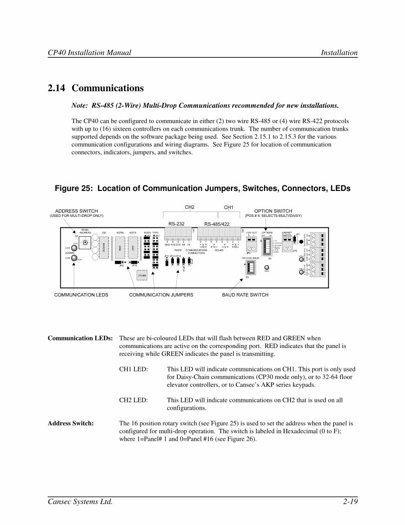
2.19 Firmware Status LED
The FS LED provides a visual indication that the CP40 processor is running and is the first indication that
the board is functioning properly. This LED should normally be flashing ON/OFF in one-second intervals.
Figure 41: Firmware Status LED
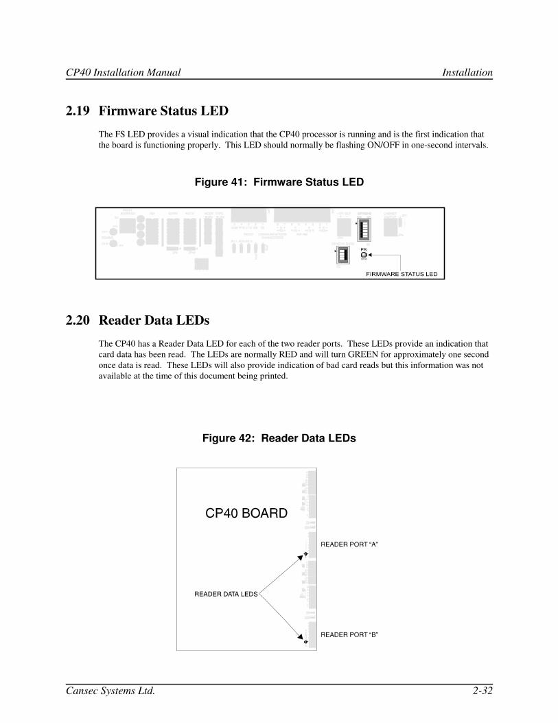
2.20 Reader Data LEDs
The CP40 has a Reader Data LED for each of the two reader ports. These LEDs provide an indication that
card data has been read. The LEDs are normally RED and will turn GREEN for approximately one second
once data is read. These LEDs will also provide indication of bad card reads but this information was not
available at the time of this document being printed.
Figure 42: Reader Data LEDs
CP40 Installation Manual Installation
Cansec Systems Ltd. 2-33
2.21 Option Dip Switch (S2)
The following describes the functions of the Option Dip Switch.
Note: The Reset Switch must be pressed in order for the functions to take effect once a switch setting has
been changed.
SWITCH / LABEL
FUNCTION
1- I/O
ON: When SIOPT-16 board is installed
OFF: When there is no SIOPT-16 board installed. In the OFF position, the four spare on-
board points are functional if programmed from the host (PassMaster or Maestro).
Note: Elevator firmware is required for elevator configurations. This switch has no function
when elevator firmware is installed. 2- MASTER
ON: Bypasses End of Line Resistors (CA-EOLRES).
OFF: Disables this feature.
3- MODEM
ON: Reserved for future use. Turn OFF
OFF: Disables this feature. 4- MULTI / DAISY
ON: Enables DAISY-CHAIN communications
OFF: Enables MULTI-DROP communications 5- CLR
ON: Then press RESET switch to erase the CP40's database and return panel to virgin state.
The CP40 Firmware Status LED will flash rapidly when initialization is complete. To return the
panel to normal operating mode, turn switch to OFF and press reset.
OFF: Normal operation 6- DIAG
ON: Then press RESET to cycle all outputs ON/OFF in one second intervals, including I/O