http://www.egr.unlv.edu/~b1morris/cpe300/ CPE300: Digital System Architecture and Design Fall 2011 MW 17:30-18:45 CBC C316 Pipelining Hazards, Instruction-Level Parallelism, Microprogramming 11162011
Pipelining • Process of issuing a new instruction before the previous
one has completed execution ▫ Favorite technique for RISC processors ▫ Hide latency of instruction execution (multiple clock cycles
for a single instruction) • Goal to keep equipment busy as much of the time as
possible ▫ Total throughput may be increased by decreasing the
amount of work done at a given stage and increasing the number of stages (simple tasks to accomplish instruction execution)
• Consequences for fetch-execute cycle ▫ Previous instruction not guaranteed to be completed before
next operation begins ▫ Results of previous operation not free available at next
operation
3
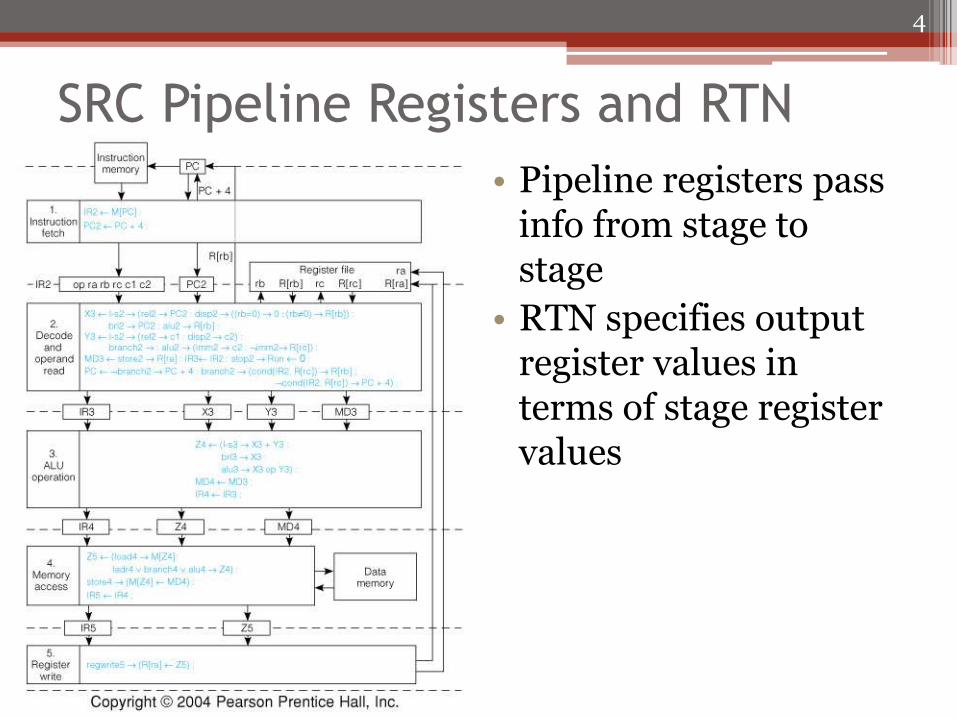
SRC Pipeline Registers and RTN
• Pipeline registers pass info from stage to stage
• RTN specifies output register values in terms of stage register values
4
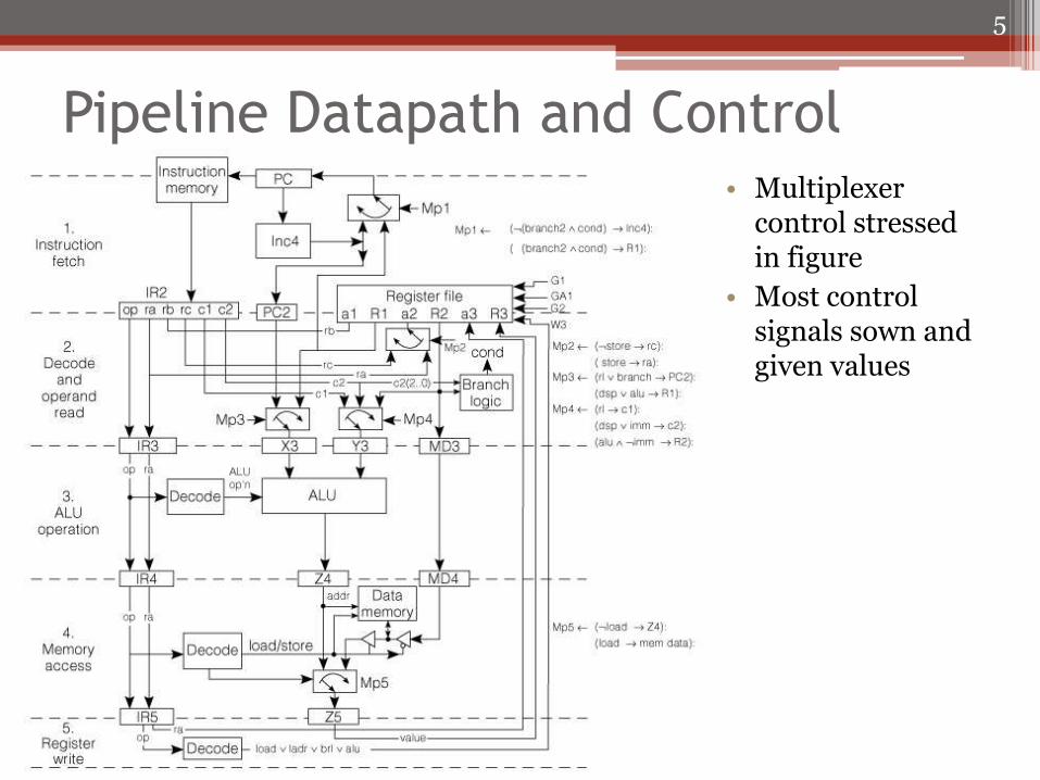
Pipeline Datapath and Control • Multiplexer
control stressed in figure
• Most control signals sown and given values
5
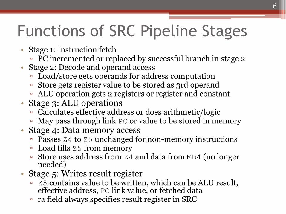
Functions of SRC Pipeline Stages • Stage 1: Instruction fetch
▫ PC incremented or replaced by successful branch in stage 2 • Stage 2: Decode and operand access
▫ Load/store gets operands for address computation ▫ Store gets register value to be stored as 3rd operand ▫ ALU operation gets 2 registers or register and constant
• Stage 3: ALU operations ▫ Calculates effective address or does arithmetic/logic ▫ May pass through link PC or value to be stored in memory
• Stage 4: Data memory access ▫ Passes Z4 to Z5 unchanged for non-memory instructions ▫ Load fills Z5 from memory ▫ Store uses address from Z4 and data from MD4 (no longer
needed) • Stage 5: Writes result register
▫ Z5 contains value to be written, which can be ALU result, effective address, PC link value, or fetched data
▫ ra field always specifies result register in SRC
6
Pipeline Hazards
• Deterministic events that are a side-effect of having instructions in pipeline
▫ Parallel execution
▫ Instruction dependence – instruction depends on result of previous instruction that is not yet completely executed
• Two categories of hazards
▫ Data hazards – incorrect use of old and new data
▫ Branch hazards – fetch of wrong instruction on a change in the PC
7
Branch Hazards
• Branch targets determined in stage 2 ▫ Instruction following the branch instruction will enter
the pipeline ▫ Branch delay states following instruction gets executed
without regard for branch action Branch delay slot instruction executed before branch is
taken
• Branch prediction ▫ Improve pipeline performance by trying to guess if the
branch will be taken Keep information to tell if instruction already seen and
PC values after execution
Delay only when prediction is wrong
▫ Lots effort in designing prediction schemes
8
Data Hazards
• Incorrect use of old and new data • Read after write (RAW) hazard
▫ Flow dependence – instruction uses data produced by a previous one
• Write after read (WAR) hazard ▫ Anti-dependence – instruction writes a new value
over one that is still needed by a previous instruction
• Write after write (WAW) hazard ▫ Output dependence – two parallel instructions
write the same register and must do it in the order they were issued
9
Detecting Hazards
• Pairs of instructions must be considered to detect hazards
• Data is normally available after being written to a register ▫ Use data forwarding to make it available as early as
stage it was produced Stage 3 output for ALU results
Stage 4 for memory fetch
▫ Receive data as late as stage in which they are used Operands normally needed in stage 2
Stage 2 for branch target
Stage 3 for ALU operands and address modifier
Stage 4 for stored register
10
Data Hazards in SRC
• All data memory access occurs in stage 4 meaning all memory reads and writes are sequential and do not cause hazards
• Registers written in the last stage
▫ WAW and WAR hazards do not occur
▫ Two writes occur in order issued
▫ Write always follows a previously issued read
• Only RAW hazards exist
▫ Values written to register at end of stage 5 may be needed by a following instruction at beginning of stage 2
11
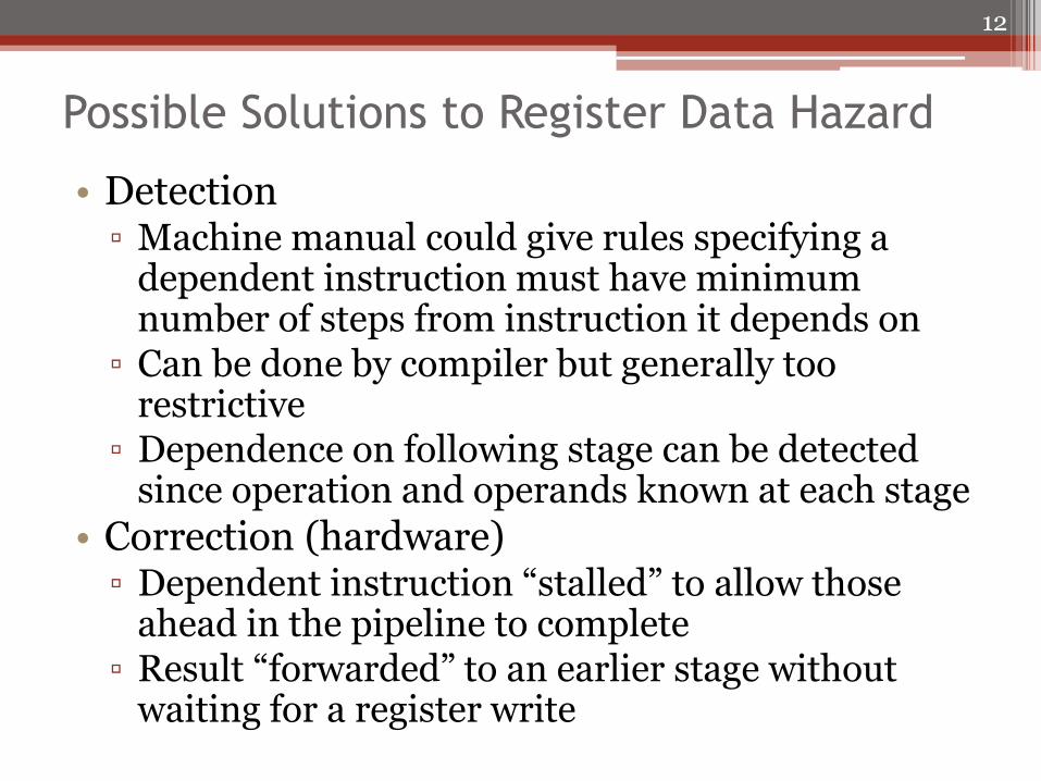
Possible Solutions to Register Data Hazard
• Detection ▫ Machine manual could give rules specifying a
dependent instruction must have minimum number of steps from instruction it depends on
▫ Can be done by compiler but generally too restrictive
▫ Dependence on following stage can be detected since operation and operands known at each stage
• Correction (hardware) ▫ Dependent instruction “stalled” to allow those
ahead in the pipeline to complete ▫ Result “forwarded” to an earlier stage without
waiting for a register write
12
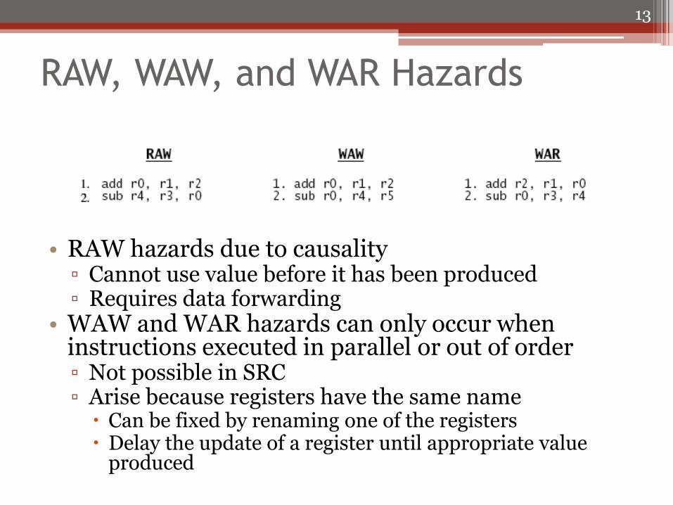
RAW, WAW, and WAR Hazards
• RAW hazards due to causality ▫ Cannot use value before it has been produced ▫ Requires data forwarding
• WAW and WAR hazards can only occur when instructions executed in parallel or out of order ▫ Not possible in SRC ▫ Arise because registers have the same name
Can be fixed by renaming one of the registers Delay the update of a register until appropriate value
produced
13
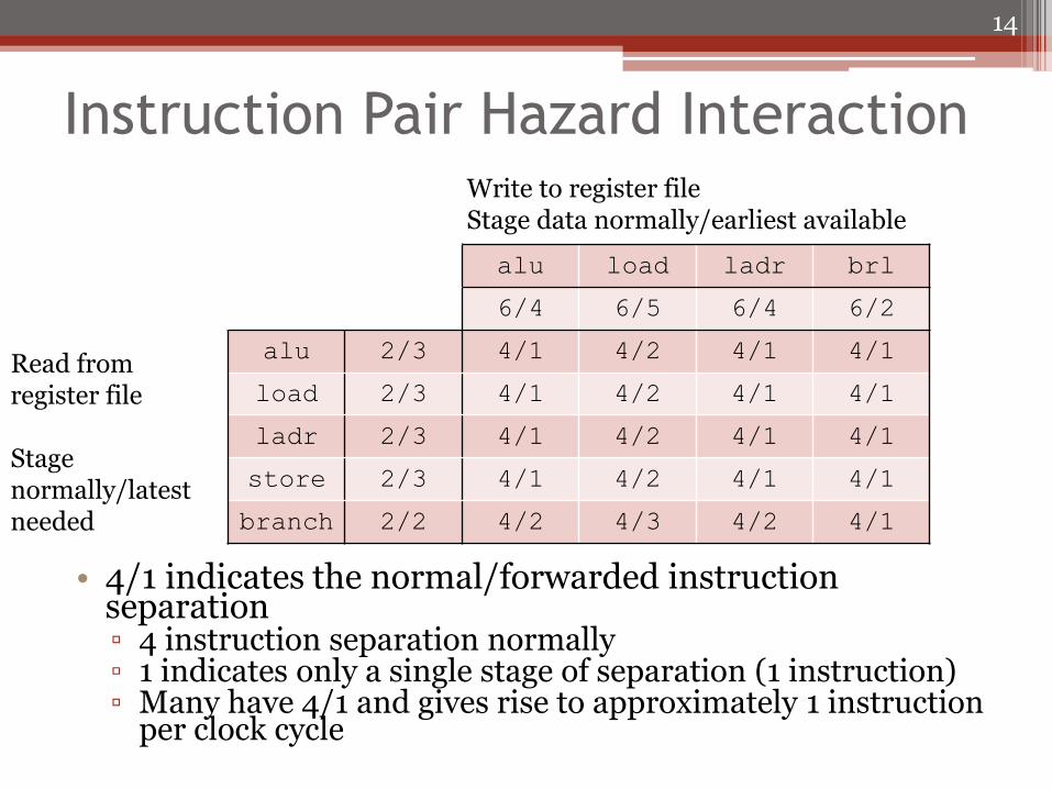
Instruction Pair Hazard Interaction
• 4/1 indicates the normal/forwarded instruction separation ▫ 4 instruction separation normally ▫ 1 indicates only a single stage of separation (1 instruction) ▫ Many have 4/1 and gives rise to approximately 1 instruction
per clock cycle
14
alu load ladr brl
6/4 6/5 6/4 6/2
alu 2/3 4/1 4/2 4/1 4/1
load 2/3 4/1 4/2 4/1 4/1
ladr 2/3 4/1 4/2 4/1 4/1
store 2/3 4/1 4/2 4/1 4/1
branch 2/2 4/2 4/3 4/2 4/1
Read from register file Stage normally/latest needed
Write to register file Stage data normally/earliest available
Delays Unavoidable by Forwarding
• Loaded values cannot be available to next instruction even with forwarding ▫ Restrict compiler from putting dependent instruction
in position right after load (next 2 positions for branch)
• Target register cannot be forwarded to branch from immediately preceding instruction ▫ Code restricted so branch target is not changed by
instruction preceding branch (previous 2 instructions if load from memory)
▫ Not to be confused with branch delay slot Branch delay – dependence fetch on branch
This is branch instruction dependent on some instruction before it
15
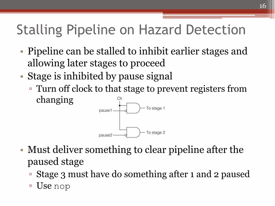
Stalling Pipeline on Hazard Detection
• Pipeline can be stalled to inhibit earlier stages and allowing later stages to proceed
• Stage is inhibited by pause signal
▫ Turn off clock to that stage to prevent registers from changing
• Must deliver something to clear pipeline after the paused stage
▫ Stage 3 must have do something after 1 and 2 paused
▫ Use nop
16
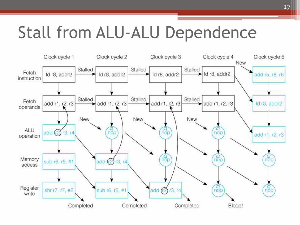
Stall from ALU-ALU Dependence
17
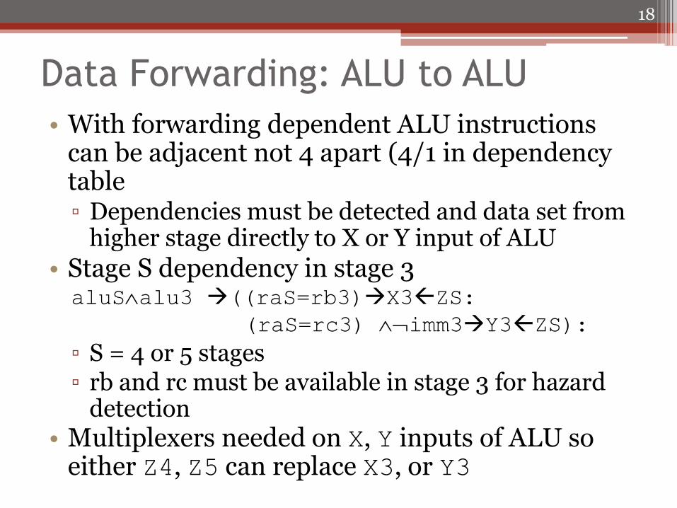
Data Forwarding: ALU to ALU
• With forwarding dependent ALU instructions can be adjacent not 4 apart (4/1 in dependency table ▫ Dependencies must be detected and data set from
higher stage directly to X or Y input of ALU
• Stage S dependency in stage 3 aluSalu3 ((raS=rb3)X3ZS:
(raS=rc3) imm3Y3ZS):
▫ S = 4 or 5 stages ▫ rb and rc must be available in stage 3 for hazard
detection • Multiplexers needed on X, Y inputs of ALU so
either Z4, Z5 can replace X3, or Y3
18
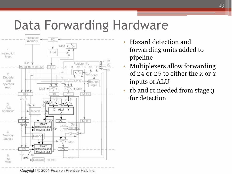
Data Forwarding Hardware • Hazard detection and
forwarding units added to pipeline
• Multiplexers allow forwarding of Z4 or Z5 to either the X or Y
inputs of ALU
• rb and rc needed from stage 3 for detection
19
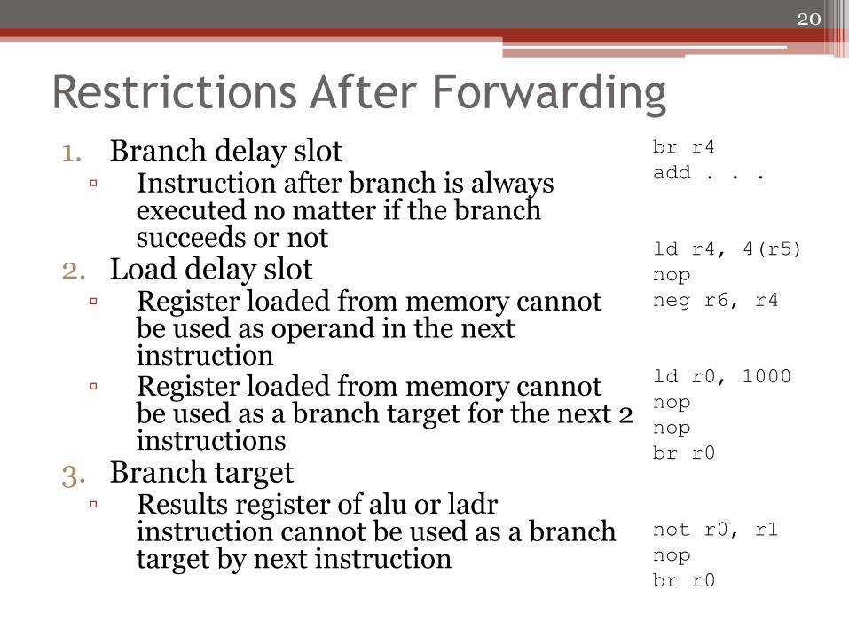
Restrictions After Forwarding 1. Branch delay slot
▫ Instruction after branch is always executed no matter if the branch succeeds or not
2. Load delay slot ▫ Register loaded from memory cannot
be used as operand in the next instruction
▫ Register loaded from memory cannot be used as a branch target for the next 2 instructions
3. Branch target ▫ Results register of alu or ladr
instruction cannot be used as a branch target by next instruction
20
br r4
add . . .
ld r4, 4(r5)
nop
neg r6, r4
ld r0, 1000
nop
nop
br r0
not r0, r1
nop
br r0
Instruction Level Parallelism • Full pipeline completes at most one instruction
every clock cycle • Fetch multiple instructions and start several at the
same time ▫ Requires multiple function units (e.g. integer, floating
point) ▫ Should be no dependence between instructions
• Superscalar architecture ▫ Dynamically fetch instructions to fill idle function
units • Very long instruction Word (VLIW) deign
▫ Statically compile long instruction words with many operations in a word to send to different function units
▫ Word size may be 128, 256, or more bits
21
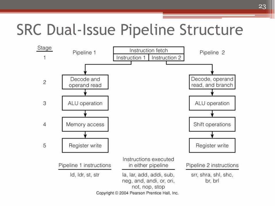
Dual Issue VLIW Version of SRC • 2 instructions per word (2 x 32 = 64 bit word) • Two pipelines
▫ Pipeline 1 can execute memory-access instructions (ld, ldr, st, and str) Only one memory access per clock cycle (64-bit word)
▫ Pipeline 2 can execute shr, shra, shc, br, and brl Expensive barrel shifter replaces memory access in stage 4 One branch instruction per word
▫ Either pipeline can execute other instructions la, lar, add, addi, sub, and, andi, or, ori, neg, not, nop, and stop
• Registers can have 4 reads and 2 writes per cycle ▫ Must provide more read/write ports or have a “shadow”
copy • No branch delay slot • Instruction forwarding wherever possible
22
SRC Dual-Issue Pipeline Structure
23
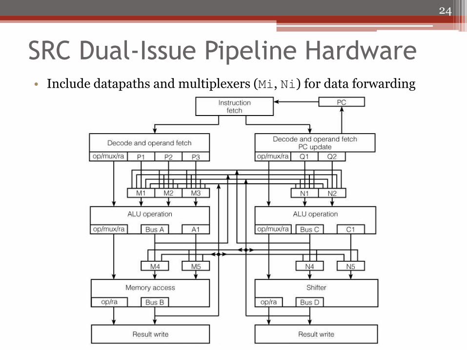
SRC Dual-Issue Pipeline Hardware • Include datapaths and multiplexers (Mi, Ni) for data forwarding
24
Superscalar Architecture
• Uses multiple pipelines to issue multiple instructions per clock cycle
• Selection of instructions done at run-time by hardware
▫ Instruction buffer used to pre-fetch instructions
▫ Dependencies between pipeline contents and buffer examined to determine which new instructions to issue
25
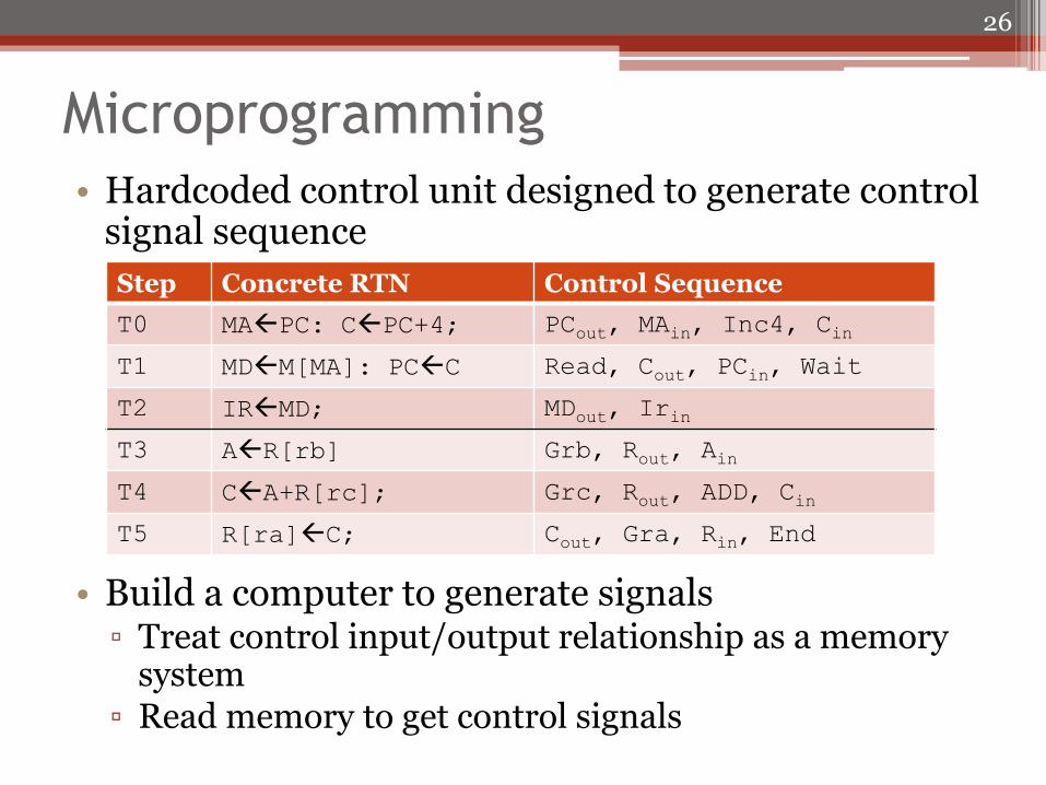
Microprogramming
• Hardcoded control unit designed to generate control signal sequence
• Build a computer to generate signals ▫ Treat control input/output relationship as a memory
system ▫ Read memory to get control signals
26
Step Concrete RTN Control Sequence
T0 MAPC: CPC+4; PCout, MAin, Inc4, Cin
T1 MDM[MA]: PCC Read, Cout, PCin, Wait
T2 IRMD; MDout, Irin
T3 AR[rb] Grb, Rout, Ain
T4 CA+R[rc]; Grc, Rout, ADD, Cin
T5 R[ra]C; Cout, Gra, Rin, End
Microcode Engine
• Generating control signals is much simpler than a general purpose processor
▫ Simplest form just reads control signals in order from read only memory
• Control store
▫ Fast local memory that contains control words
• Microinstruction
▫ Control store word contains bit pattern telling which control signals are active in a specific step
• Major issue is to determine order in which microinstructions are read
27
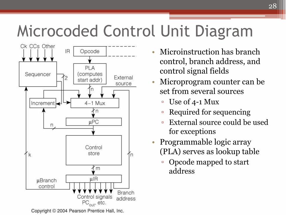
Microcoded Control Unit Diagram • Microinstruction has branch
control, branch address, and control signal fields
• Microprogram counter can be set from several sources
▫ Use of 4-1 Mux
▫ Required for sequencing
▫ External source could be used for exceptions
• Programmable logic array (PLA) serves as lookup table
▫ Opcode mapped to start address
28
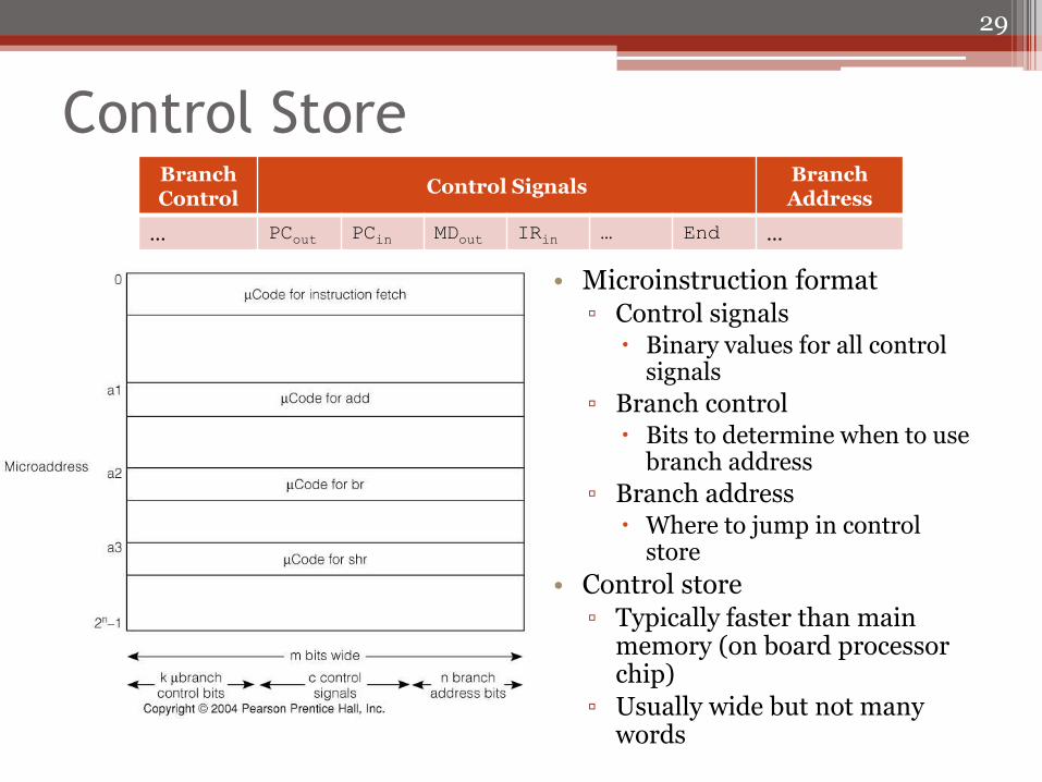
Control Store
• Microinstruction format ▫ Control signals
Binary values for all control signals
▫ Branch control Bits to determine when to use
branch address
▫ Branch address Where to jump in control
store
• Control store ▫ Typically faster than main
memory (on board processor chip)
▫ Usually wide but not many words
29
Branch Control
Control Signals Branch Address
… PCout PCin MDout IRin … End …
Hardwired vs Microcoded Control
• Hardwired control is faster
▫ Only a few gate delays
▫ Microcode requires memory fetch
• Microcode is easier to prototype
▫ Can reprogram memory chip easily
• Microcode is more flexible
▫ Change in instruction sets more accessible
30
Chapter 5 Summary
• Deals with alternative processor design strategies • Pipelining utilizes hardware to increase
performance ▫ Want 1 instruction executed per clock cycle ▫ Data forwarding, branch delay slot, and load delay slot
help approach target goal ▫ Data hazards must be detected to guarantee correct
operation with use of pipeline
• Multi-issue with instruction-level parallelism in another way to improve speed
• Microprogramming is an easy to design control strategy ▫ Treats control as memory read