Thank you for purchasing the Cobra CPI 2550inverter. Properly used, this Cobra product will give you many years of reliable service.
How Your Cobra Power Inverter Works
The Cobra power inverter is an electronic product that hasbeen designed and built to take low voltage DC (DirectCurrent) power from your automobile or other low voltagepower supplies and convert it to standard 115 volt AC(Alternating Current) power like the current you have in yourhome. This conversion process thereby allows you to use many of your household appliances and electronicproducts in automobiles, RVs, boats, tractors, trucks andvirtually anywhere else.
Customer Assistance
Should you encounter any problems with this product, or not understand its many features, please refer to this owner’smanual. If you require further assistance after reading thismanual, Cobra Electronics offers the following customer assistance services:
For Assistance in the U.S.A.
Automated Help Desk English only. 24 hours a day, 7 days a week 773-889-3087 (phone).
Customer Assistance Operators English and Spanish. 8:00 a.m. to 6:00 p.m. CT, Monday through Friday (except holidays) 773-889-3087 (phone).
Questions English and Spanish. Faxes can be received at 773-622-2269 (fax).
Technical Assistance English only. www.cobra.com (on-line: Frequently Asked Questions). English and Spanish. [email protected] (e-mail).
Before installing and using your Cobra power inverter, please read these general precautions and warnings.
Caution and Warning Statements
To make the most of this inverter, it must be installed andused properly. Please read the installation and operatinginstructions carefully before installing and using it. Specialattention must be paid to the CAUTION and WARNINGstatements in the manual.
CAUTION Statements specify conditions which could cause damage to the unit or other equipment.
WARNING Statements identify conditions that could result in personal injury or loss of life.
General Precautions
1. Never install the inverter in a boat’s engine compartmentwhere gas and battery fumes are present.
2. Do not operate the inverter if it has been dropped or damaged in any way.
3. Do not open the inverter; it contains no user-serviceable parts. Attempting to service unit could cause electrical shock.
NOTE Internal components remain charged after all power is disconnected.
4. Do not expose the inverter to rain, snow, bilge water or spray.
5. Do not obstruct the ventilation openings.
6. Do not install the inverter in zero-clearance compartment.
CAUTION This inverter should be used in negative ground applications only.
CAUTION
3Nothing Comes Close to a Cobra®2 English
Important Safety Information
Introduction
WARNING Power inverters contain components that tend to produce arcs or sparks. To prevent fire or explosion, do not install the inverter in areas or compartments containing batteries orflammable materials or in locations that requireignition-protected equipment.
WARNING To reduce the risk of fire, do not cover or obstruct the ventilation openings. Do not installinverter in zero-clearance compartment.
Caution: Rechargeable Appliances
Certain chargers for small nickel cadmium batteries can be damaged if connected to the Cobra 2500 watt inverter.Two particular types of equipment are prone to this problem:
1. Small battery-operated appliancessuch as flashlights, razors, and nightlights that can be plugged directlyinto an AC receptacle to recharge.
2. Certain battery chargers for batterypacks used in hand power tools. These chargers have aWARNING label stating thatdangerous voltages are present at the battery terminals.
This problem does not occur with the vast majority of batteryoperated equipment. Most use a separate charger ortransformer that is plugged into the AC receptacle andproduces a low voltage output. If the label on the AC adapteror charger states that it produces a low voltage AC or DC output (less than 30 volts), the inverter will have no problem powering the adapter safely.
Cobra 2500 Watt Output Waveform
Some very sensitive electronic equipment may not operate satisfactory on “square wave” or “modified sine wave.” The output waveform is referred to as “square wave” or “modified sine wave.” It is a steppedwaveform designed to have characteristics similar to the sine wave shape of utility power. A waveform of this nature is suitable for most AC loads (including linear and switching power suppliers used in electronicequipment, transformers and motors).
Plug In Directly
Dangerous Voltages
Important Safety Information
Introduction
5Nothing Comes Close to a Cobra®4 English
Quick Evaluation
IntroductionQuick Evaluation
Introduction
Quick Evaluation Before Installation•
This section provides you with basic information about the inverter and how to check its performance beforeinstallation.
Be sure to have on hand:
£ A 12 volt DC power source (such as a vehicle battery).
The power source must providebetween 11 and 15 volts DC and beable to supply enough current to runthe test load. As a rough guide, dividethe wattage of the test load by 10 toget the current (in amperes) the powersource must deliver.
£ A set of cables to connect the power source to the inverter(not included).
The cables must be as short and thick as possible in orderto reduce the voltage drop between the power source andthe inverter when drawing current from the power source.
If the cable suffers an excessive voltage drop, the invertermay shut down when drawing higher currents because thevoltage at the inverter dropped below 10 volts.
#4 AWG stranded copper cable is recommended. It shouldbe no longer than four feet (one and one-half meters).
The end of the cable that connects to the inverter must haveits insulation stripped off for about one-half inch (one andone-half cm) back from the end, exposing the bare copper.
The other end of the cable, which connects to the powersource, must be terminated with a lug or other connector thatprovides a secure, low resistance connection.
For example, if the power source is a battery, the cablemust be terminated with a battery terminal that clamps tothe post on the battery.
£ A test load that can be plugged into the AC receptacle on theinverter for short term testing at a low power level. Thefollowing cables are recommended for testing low powerlevel test loads only.
To check your inverter’s performance before installation:
1. Turn the inverter off (see page 14 fordetails). If the power source is a DCpower supply, switch it off as well.
2. Connect cables to power inputterminals (see page 8 for details).
3. Connect cables to power source (seepage 8 for details).
4. Check to make sure all connectionsare secure.
5. Turn the inverter on. If the power source is a DC power supply,switch it on first.
6. Plug in the test load.
The inverter should supply power to the load. If the inverter is notworking properly, refer to thetroubleshooting guide on page 18 or power and protection indicatorssection on page 16.
Power Supply
Test Load
On/Off Switch to Off
Connect Terminals
Connect Power Source
On/Off Switch to On
Connect Test Load
7Nothing Comes Close to a Cobra®6 English
Mounting
Installation Requirements•
The inverter must be installed in an area that meets all of the following requirements:
A. DryDo not place in an area where water can drip or splash on the inverter.
B. CoolAmbient air temperature should be between 30°F and 105°F (0°C and 40°C). The cooler the better.
C. VentilateAllow at least one inch (three cm) of clearance around theinverter for proper airflow. Make sure that ventilationopenings on the ends of the unit are not obstructed.
D. SafeDo not install the inverter in the same compartment as a battery or in any compartment that contains flammable liquids such as gasoline.
E. Close to BatteryInstall unit as close to battery as possible (without being inthe same compartment) to minimize the length of cable required to connect the inverter to the battery. It is better and cheaper to run longer AC wires than longer DC wires (cables).
CAUTION To avoid fire, do not cover or obstructventilation openings. Do not install inverter in a zero-clearance compartment. Overheating may result.
CAUTION The inverter must only be connected tobatteries with a nominal output voltage of 12 volts. It will not work with a 6 volt battery, and will bedamaged if it is connected to a 16 volt battery.
WARNING This unit contains components which can produce arcs or sparks. To prevent fire or explosion, do not install in compartmentscontaining a battery or flammable materials, or in a location which requires ignition protected equipment.
WARNING This unit is suitable for installation in negative ground applications only. Do not attempt toinstall to a positive ground application.
Mounting•
To mount your inverter:
1. Place the inverter on a flat surface with the mounting bracket against the mounting surface.
2. Mount to secure surface using mounting hardware that is corrosion resistant (not included).
The inverter can be mounted horizontally or vertically.
Installation
Mounting Brackets
Mounting Hardware
Installation Requirements
Installation
9Nothing Comes Close to a Cobra®8 English
Connecting Cables (not included)•
Power wire and wiring are very important to the performance ofthe inverter. Because the inverter has a low voltage, highcurrent input, low resistance wiring is essential between thebattery and inverter. This is so it can deliver the maximumamount of energy to the load.
Use only copper wire. Aluminum wire has about one-thirdmore resistance than copper wire of the same size, plus it isdifficult to make good, low-resistance connections toaluminum wire.
We recommend two #4 AWG copper cables (90°C insulationrating) as the minimum size for connections between thebattery and inverter.
Keep the cable length as short as possible, no more thanfour feet (one and one-half meters). This will keep thevoltage drop to a minimum.
If the cable has too much voltage drop, the inverter may shut down when drawing higher currents becausevoltage at the inverter may drop below 10 volts. If you mustuse longer cables, choose thicker cables, such as #2 AWG,and trim the ends of the cable to fit the terminals.
To connect the cables between the inverter and the battery:
1. Turn the On/Off Switch on the inverter to the off position. Ifthe power source is a DC power supply, switch it off aswell.
2. On the end of the cable that connects to the inverter, stripback the insulation about one-half inch (one and one-halfcm), exposing the bare copper conductor.
3. Connect cables to the Power Input Terminals on right sidepanel of the inverter. The red terminals are positive (+) andthe black terminals are negative (-). Insert the bare ends ofthe cables into the terminals and tighten the screws toclamp the wires safely.
4. Connect cables to the power source:
a. Connect each cable from the Negative (Black) Terminalsof inverter to the Negative Terminalof the power source. Make a secure connection.
b. Connect each cable from the Positive (Red) Terminals ofthe inverter to the Positive Terminalof the power source (the battery’s main fuse or the battery selector switch, if you are using one). Makea secure connection.
Connecting Cables Connecting Cables
Installation
Installation
On/Off Switch to Off
Strip the Insulation
Insert Bare Cables
Connect Cables
11Nothing Comes Close to a Cobra®10 English
You might observe a spark when you make this connection, sincecurrent can flow to charge capacitors in the inverter.
All power connections to your Cobra inverter must be Positiveto Positive and Negative to Negative.
CAUTION Electrical installations must meet local and national wiring codes, and should be performed by a qualified electrician.
CAUTION Do not connect the inverter and another ACsource (such as a generator or utility power) to the AC wiring at the same time. The inverter will be damaged if its output is connected to ACvoltage from another source. Damage can even occurif the inverter is switched off.
CAUTION Do not connect the inverter to an AC branchcircuit that has high-power consumption loads. It willnot operate electric heaters, air conditioners, stoves,and other electrical appliances that consume more than 2500 watts.
CAUTION Loose connectors result in excessive voltagedrop and may cause over heated wires and melted insulation.
CAUTION Reverse polarity connections (positive to negative) will blow internal fuses in the inverter andmay permanently damage the unit. Such damage is notcovered by the warranty.
CAUTIONWe recommend a main fuse in the battery’spositive cable to protect against DC wiring short circuits (external to the inverter). The fuse should be as close to the battery as possible.We recommend a Buss Fuse ANL-250 or equivalent. The specific fuse ampere rating shouldbe sized to allow operation of all your DC powered equipment.
CAUTION Remove any jewelry (watch, ring, etc.). Be careful not to short circuit the battery with anymetallic object (wrench, etc.).
WARNING If you are making a permanent AC connectionto the inverter, make sure that the AC wiring steps are performed before any DC wiring isdone. (DC hook-up energizes internal components,regardless of the position of the On/Off Switch). Working on AC connections in such a circumstance may result in an electric shock.
WARNING 115 volt AC power is potentially lethal. Do not work on AC wiring when it is connected to the inverter (even if it is switched off) unless the DC power source is physically disconnected from the inverter. Also, do not work on AC wiring if it is connected to another AC power source such as a generator or the utility line.
WARNING You may observe a spark when making the connection because current can flow to charge the capacitors in the inverter. Do not make this connection in the presence of flammable fumes. Explosion or fire may result. Thoroughly ventilate the battery compartmentbefore making this connection.
NOTE If only one power source is used, connect bothcables from the negative terminal of the inverter to thenegative terminal of the power source. Then connectboth cables from the positive terminals of the inverter tothe positive terminal of the power source.
Connecting Cables Connecting Cables
Installation
Installation
13Nothing Comes Close to a Cobra®12 English
Power Consumption•
For each piece of equipment you will be operating from theinverter, you must determine the battery’s reserve capacity(how long the battery can deliver a specific amount of current —in automotive batteries, usually 25 ampere) or ampere-hour capacity (a measure of how many amperes abattery can deliver for a specified length of time).
Example – Reserve capacity: a battery with a reservecapacity of 180 minutes can deliver 25 ampere for 180 minutes before it is completely discharged.
Example – Ampere-hour capacity: a battery with anampere-hour capacity of 100 ampere-hours can deliver 5ampere for 20 hours before it is completely discharged.
To determine the battery ampere-hour capacity you require:
1. Determine how many watts each piece of equipmentconsumes. This can normally be found on the product label.If only the current draw is given, multiply the current drawby 115 to get the watt consumption.
2. Estimate the time (in hours) that each piece of equipment willbe running between battery charging cycles.
3. Calculate the total watt-hours of energy consumption(power x operating time) using the average powerconsumption and the total estimated running time (in hours). Power x Operating Time = Watt-Hours.
4. Divide the watt-hours by 10 to determine how many powersupply’s (12 volt) ampere-hours will be consumed.
Ground Wiring•
There is a screw on the rear panel for Chassis Ground. This isto connect the chassis of the inverter to ground.
The Chassis Ground Screw must be connected to a groundingpoint, which will vary depending on where the unit is installed. Use a #8 AWG copper wire (preferably with green/yellow insulation) to connect the chassis ground screw to the grounding point.
In a vehicle: Connect the Chassis Ground to the chassis of the vehicle.
In a boat: Connect to the Boat Grounding System.
In a fixed location: Connect the Chassis Ground Screw toearth ground by connecting to a ground rod (a metal rodpounded into the earth) or other proper service entranceground.
Chassis Ground
Power Consumption Ground Wiring
Installation
Installation
Laptop
50 watts x 2 hours = 100 watt-hours
TV/VCR (up to 25")
115 watts x 3 hours= 345 watt-hours
Blender
300 watts x 15 minutes = 75 watt-hours
15Nothing Comes Close to a Cobra®14 English
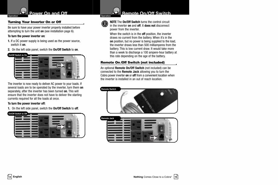
Turning Your Inverter On or Off•
Be sure to have your power inverter properly installed beforeattempting to turn the unit on (see installation page 6).
To turn the power inverter on:
1. If a DC power supply is being used as the power source,switch it on.
2. On the left side panel, switch the On/Off Switch to on.
The inverter is now ready to deliver AC power to your loads. Ifseveral loads are to be operated by the inverter, turn them onseparately, after the inverter has been turned on. This willensure that the inverter does not have to deliver the startingcurrents required for all the loads at once.
To turn the power inverter off:
1. On the left side panel, switch the On/Off Switch to off.
NOTE The On/Off Switch turns the control circuit in the inverter on and off. It does not disconnectpower from the inverter.When the switch is in the off position, the inverter draws no current from the battery. When it’s in the on position, but no power is being supplied to the load,the inverter draws less than 500 milliamperes from thebattery. This is low current draw. It would take morethan a week to discharge a 100 ampere-hour battery atthis rate depending on the age of the battery.
Remote On /Off Switch (not included)•
An optional Remote On/Off Switch (not included) can beconnected to the Remote Jack allowing you to turn the Cobra power inverter on or off from a convenient location whenthe inverter is installed in an out of reach location.
Power On and Off
OperationRemote On/Off Switch
Operation
On/Off Switch to On
Remote Switch
Remote Jack
On/Off Switch to Off
17Nothing Comes Close to a Cobra®16 English
Power and ProtectionIndicators
OperationOperating Limits
Operation
Power and Protection Indicators•
The power and protection indicators include a green light, ared light, an alarm and a current meter.
Green Light
Power on – The green light should remain on steady.
Red Light and/or Alarm
Current overload – The red light will turn onmomentarily, thenthe inverter will shutdown. The inverter will continue to checkfor appropriate current levels while trying to restart the load.
DC input voltage overload – The red light will turn on and theinverter will shutdown. The inverter will continue to check forappropriate voltage levels while trying to restart the load.
DC input voltage shortage – As a warning that the voltage isgetting low, the internal alarm will sound. When the voltage istoo low, the inverter will shutdown and the red light will turnon. The inverter will continue to check for appropriate voltagelevels while trying to restart the load.
Temperature overload – The red light will turn onmomentarily, then the inverter will shutdown. The inverter willcontinue to check for appropriate temperature levels and thered light will continue to blink while trying to restart the load.
NOTE A momentary sound of the internal alarm and/orflash of the red light is normal at start up.
Current Meter
The current meter indicates thecurrent drawn from the battery. It will not indicate the current drawn by other loads also connectedto the battery.For long term operation, the current meter should remain in the middle of the bar graph.
Operating Limits•
Power Output
The inverter can deliver 2500 watts for about 60 minutes. Theinverter must cool for 15 minutes before it can resumeoperation at 2500 watts. Note: The wattage rating applies to resistive loads.
The inverter will operate most AC loads within its powerrating. Some induction motors used in freezers, pumps, andother motor-operated equipment require very high surgecurrents to start. The inverter may not be able to start some ofthese motors even though their rated current draw is within the inverter’s limits. The inverter will normally start single phase induction motors rated at one-half HP or less.
Input Voltage
The inverter will operate from input voltage ranging from 10 volts to 15 volts. Optimum performance will occurwhen the voltage is between 12 volts and 14 volts. If thevoltage drops below 10.5V+/-0.3V, an audible low batterywarning will sound. The inverter will shut down if the inputvoltage drops below 9.5V+/-0.3V. This protects the batteryfrom being over-discharged. It will restart when the inputvoltage exceeds 12V+/-0.3V.
The inverter will also shut down if the input voltage exceeds15.75V+/-0.75V. This protects the inverter against excessive input voltage. Although the inverter has protection against over-voltage, it may still be damaged ifthe input voltage were to exceed 16 volts.
Improve ventilation;Make sure ventilationopenings in theinverter are notobstructed.
Reduce ambienttemperature.
Make sure the inverter isconnected to 12V battery.
Check regulation of charging system.
Check load forproper operation.
Turn inverter on.
Check wiring to inverter.
Observe correct polarity.
Check connections.
Make sure battery is fully charged.
Troubleshooting Guide•
21Nothing Comes Close to a Cobra®
Maintenance•
Very little maintenance is required to keep the inverter operatingproperly. The exterior of the unit should be cleaned periodically with adamp cloth to prevent accumulation of dust and dirt. At the same time,tighten the screws on the DC input terminals. Be sure vents and fansare free of dust or debris.
Product Service•
If you have any questions about operation or installing your newCobra product, or if you are missing parts…
Please call Cobra first! DO NOT RETURN THIS PRODUCT TO THE STORE! See customer assistance on page A1.If your product should require factory service, please call Cobra firstbefore sending your power inverter. This will ensure the fastest turn-around time on your repair. You may be asked to send your power inverter to the Cobra factory.
It will be necessary to furnish the following to have the productserviced and returned.1. For warranty repair include some form of proof-of-purchase, such as
a mechanical reproduction or carbon copy of a sales receipt. If yousend the original receipt, it cannot be returned.
2. Send the entire product.
3. Enclose a description of what is happening with the power inverter.Include a typed or clearly printed name and address of where the power inverter is to be returned.
4. Pack power inverter securely to prevent damage in transit. If possible, use the original packing material.
5. Ship prepaid and insured by way of a traceable carrier such as United Parcel Service (UPS) or Priority Mail to avoid loss in transit to: Cobra Factory ServiceCobra Electronics Corporation6500 West Cortland StreetChicago, Illinois 60707 USA.
6. If the power inverter is in warranty, upon receipt of your powerinverter, it will either be repaired or exchanged depending on themodel. Please allow approximately three to four weeks beforecontacting Cobra for status. If the power inverter is out of warranty, aletter will automatically be sent informing you of the repair charge or replacement charge.
If you have any questions, please call 773-889-3087 for assistance.
Maintenance and Product Service
Customer Assistance
20 English
Limited Two-Year Warranty •
For Products Purchased in the U.S.A.
Cobra Electronics Corporation warrants that its Cobra power inverter,and the component parts thereof, will be free of defects inworkmanship and materials for a period of two years from the date offirst consumer purchase. This warranty may be enforced by the firstconsumer purchaser, provided that the product is utilized within theU.S.A.
Cobra will, without charge, repair or replace, at its option, defectivepower inverters, products or component parts upon delivery to the CobraFactory Service department, accompanied by proof of the date of firstconsumer purchase, such as a duplicated copy of a sales receipt.
You must pay any initial shipping charges required to ship the productfor warranty service, but the return charges will be at Cobra’s expense,if the product is repaired or replaced under warranty. This warrantygives you specific legal rights, and you may also have other rightswhich may vary from state to state.
Exclusions: This limited warranty does not apply:
1. To any product damaged by accident.
2. In the event of misuse or abuse of the product or as a result of unauthorized alterations or repairs.
3. If the serial number has been altered, defaced, or removed.
4. If the owner of the product resides outside the U.S.A.
All implied warranties, including warranties of merchantability and fitness for a particular purpose are limited in duration to the lengthof this warranty. Cobra shall not be liable for any incidental,consequential or other damages; including, without limitation, todamages resulting from loss of use or cost of installation.
Some states do not allow limitations on how long an implied warrantylasts and/or do not allow the exclusion or limitation of incidental or consequential damages, so the above limitations maynot apply to you.
For Products Purchased Outside the U.S.A.
Please contact your local dealer for warranty information.
Trademark Acknowledgement •
Cobra®, Nothing Comes Close to a Cobra® and the snake design are registered trademarks of Cobra Electronics Corporation, USA. Cobra Electronics Corporation™ is a trademark of Cobra Electronics Coproration, USA.
Warranty and TrademarkAcknowledgement
Warranty
23Nothing Comes Close to a Cobra®22 English
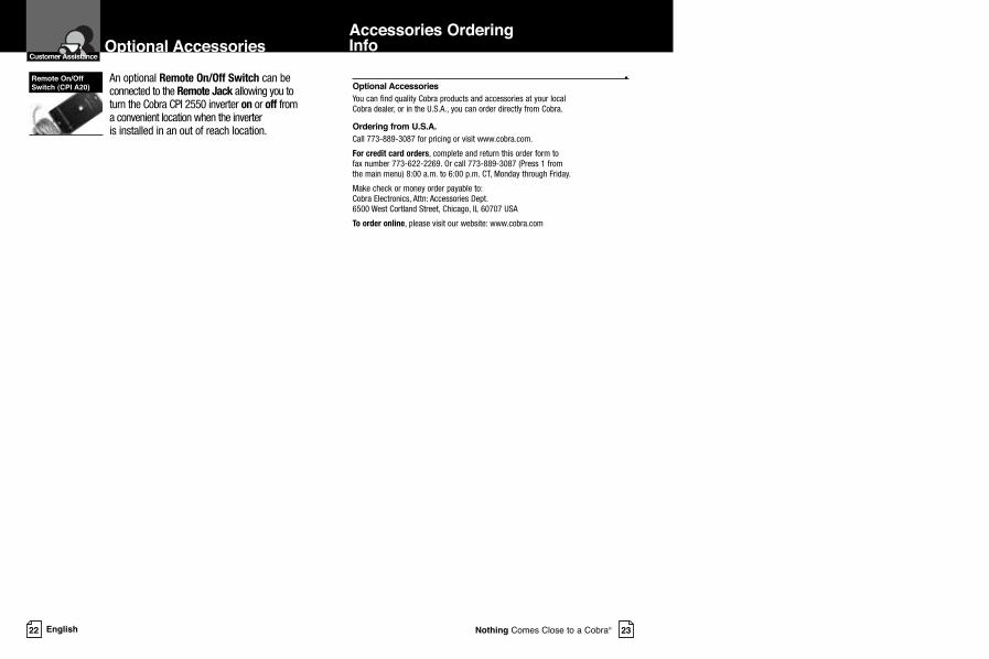
Optional Accessories
You can find quality Cobra products and accessories at your local Cobra dealer, or in the U.S.A., you can order directly from Cobra.
Ordering from U.S.A.
Call 773-889-3087 for pricing or visit www.cobra.com.
For credit card orders, complete and return this order form to fax number 773-622-2269. Or call 773-889-3087 (Press 1 from the main menu) 8:00 a.m. to 6:00 p.m. CT, Monday through Friday.
Make check or money order payable to: Cobra Electronics, Attn: Accessories Dept.6500 West Cortland Street, Chicago, IL 60707 USA
To order online, please visit our website: www.cobra.com
•An optional Remote On/Off Switch can beconnected to the Remote Jack allowing you toturn the Cobra CPI 2550 inverter on or off froma convenient location when the inverter is installed in an out of reach location.