+ All Categories
Home > Documents > CPRI Design Example · CPRI Design Example Introduction In wireless applications, a fundamental...

CPRI Design Example · CPRI Design Example Introduction In wireless applications, a fundamental...

Date post: 17-Mar-2020
Category:
Upload: others
View: 16 times
Download: 1 times
Share this document with a friend
13
CPRI Design Example Introduction In wireless applications, a fundamental path is the Remote Radio Head (RRH) to Base Station (BTS) path. In the downlink, an analog radio signal is translated into a digital format in which it can then be processed and manipulated. In the uplink direction, the opposite processing is applied. This example design will showcase three of the functions that are part of these data paths: compression, mapping of IQ samples into a CPRI payload, and a CPRI link that carries Control and IQ Payload between the RRH and the BTS. The modules/functions showcased in this design example are part of Altera’s solution for wireless applications Requirements Arria 10 PCIe Development Kit FMC Loopback Card Quartus II 16.0 Arria 10 PCIe Development Kit ClockControl Altera_CPRI_IQ_Mapper Tool CPRI v6 IP License ModelSim 10.1b or newer version High-Level Description A high-level block diagram of the design is shown in Figure 1.0. This design example connects Compression/DeCompression, IQ Mapper/DeMapper, and CPRI IP modules. IQ samples are generated by Linear Feedback Shift Registers (LFSR) and are driven into the Compression Modules. After compression the IQ samples are mapped by the IQ Mapper module and are then driven into the CPRI IP. The CPRI module implements the CPRI protocol. It loads the IQ samples unto the CPRI IQ Data Plane. In this example the CPRI transmit serial link is routed back to the receive serial link, implementing an electrical serial loopback. In the receive direction (uplink), the IQ samples are extracted from the CPRI Frame by the CPRI module and are sent to the IQ DeMapper. From the DeMapper, the IQ samples go to the DeCompression modules. To show the integrity of the IQ data and the impact of compression on the IQ data, this design example uses an Error Vector Magnitude module. The uncompressed IQ Data, generated by the LFSRs, and the De-Compressed IQ Data received in the uplink direction (output of the DeCompression modules) are sent into the EVM module which calculates a difference in magnitude between the two.
Transcript

CPRI Design Example

Introduction In wireless applications, a fundamental path is the Remote Radio Head (RRH) to Base Station (BTS) path.

In the downlink, an analog radio signal is translated into a digital format in which it can then be

processed and manipulated. In the uplink direction, the opposite processing is applied. This example

design will showcase three of the functions that are part of these data paths: compression, mapping of

IQ samples into a CPRI payload, and a CPRI link that carries Control and IQ Payload between the RRH and

the BTS. The modules/functions showcased in this design example are part of Altera’s solution for

wireless applications

Requirements Arria 10 PCIe Development Kit

FMC Loopback Card

Quartus II 16.0

Arria 10 PCIe Development Kit ClockControl

Altera_CPRI_IQ_Mapper Tool

CPRI v6 IP License

ModelSim 10.1b or newer version

High-Level Description A high-level block diagram of the design is shown in Figure 1.0. This design example connects

Compression/DeCompression, IQ Mapper/DeMapper, and CPRI IP modules. IQ samples are generated

by Linear Feedback Shift Registers (LFSR) and are driven into the Compression Modules. After

compression the IQ samples are mapped by the IQ Mapper module and are then driven into the CPRI IP.

The CPRI module implements the CPRI protocol. It loads the IQ samples unto the CPRI IQ Data Plane. In

this example the CPRI transmit serial link is routed back to the receive serial link, implementing an

electrical serial loopback. In the receive direction (uplink), the IQ samples are extracted from the CPRI

Frame by the CPRI module and are sent to the IQ DeMapper. From the DeMapper, the IQ samples go to

the DeCompression modules.

To show the integrity of the IQ data and the impact of compression on the IQ data, this design example

uses an Error Vector Magnitude module. The uncompressed IQ Data, generated by the LFSRs, and the

De-Compressed IQ Data received in the uplink direction (output of the DeCompression modules) are

sent into the EVM module which calculates a difference in magnitude between the two.

Compress (16:12)

IQ

Ma

pp

er

I_decompQ_decomp

I_uncomp Q_uncomp

Compress (16:10)

Compress (16:8)

Compress (16:7)

Compress (16:6)

IQ

De

Ma

pp

er

Decompress

Decompress

Decompress

Decompress

Decompress

fifo

CP

RI

IP

LFSRLFSR

I_uncomp Q_uncomp

LFSRLFSR

fifo

fifo

fifo

fifo

fifo

fifo fifo fifo fifo fifo fifo

fifo

fifo

fifo

fifo

fifo

fifo

AxC0

AxC1

AxC5

AxC4

AxC0

AxC1

AxC4

AxC5

AxC5 EVM

I_deco

mp

Q_d

ecom

p

I_un

com

p

Q_u

nco

mp

ou

t

EVM

I_deco

mp

Q_d

ecom

p

I_un

com

p

Q_u

nco

mp

ou

t

EVM

AxC0 EVM

Figure 1.0 High-Level Block Diagram

Features Table 1.0 shows the features corresponding to each of the IP modules demonstrated in this design

example.

Table 1.0 Features

Module Feature

CPRI IP REC Master

9.8 Gbps

6 AxCs

Direct IQ Mapper Interface

Mapper 9.8 Gbps

6 AxCs

8X Sampling

20MHz LTE

Compression AxC0 : No Compression

AxC1 : 16:12 Compression

AxC2 : 16:10 Compression

AxC3 : 16:8 Compression

AxC4 : 16:7 Compression

AxC5 : 16:6 Compression

Running the Design

Setup and connect hardware

Connect the power supply to the PCIe Development Board

Connect the USB-Blaster cable to the PCIe Development Board and to a USB port on your

PC/Laptop

Insert an FMC Loopback Card on FMC Port A of the PCIe Development Board

Power On the board

Program the Clock Source

Bring up the Clock GUI, ClockControl.exe

Select the Si5338 (U14) tab

Enter 307.20 for CLK1 and click on “Set New Freq”

Close the Clock GUI

Program the FPGA Download the design, cpri_de_a10.zip

Unzip the cpri_de_a10.zip file

Change directory to qdir

Invoke Quartus and open the project, top_rec.qpf

Open SignalTAP, Tools -> SignalTAP II Logic Analyzer

Program the device with top_rec.sof

Enable the CPRI Transmitter Bring up the System Console, Tools -> System Debugging Tools -> System Console

Change directory to ../system_console

source main_run.tcl

reg_write 0x02000008 0x1

Observe the activity on SignalTAP

Simulating the Design You must have access to Modelsim 10.1b or newer.

Change directory to sim

Make the file run_sim an executable i.e. chmod 777 run_sim

Execute run_sim. i.e. ./run_sim

The run_sim script will compile the necessary libraries and components as well as the testbench. It will

bring up ModelSim with predefined nodes to trace in the Wave panel. You can detach the Wave panel

and monitor the activity on the signals being traced. The simulation will wait until Frame

Synchronization has been acquired and then it will run for 20,000 clock cycles.

IP Module Details

Compression

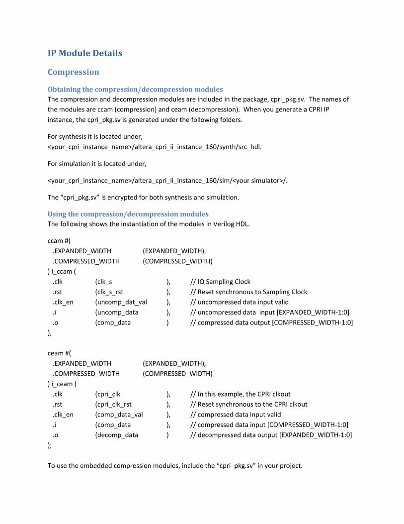
Obtaining the compression/decompression modules

The compression and decompression modules are included in the package, cpri_pkg.sv. The names of

the modules are ccam (compression) and ceam (decompression). When you generate a CPRI IP

instance, the cpri_pkg.sv is generated under the following folders.

For synthesis it is located under,

<your_cpri_instance_name>/altera_cpri_ii_instance_160/synth/src_hdl.

For simulation it is located under,

<your_cpri_instance_name>/altera_cpri_ii_instance_160/sim/<your simulator>/.

The “cpri_pkg.sv” is encrypted for both synthesis and simulation.

Using the compression/decompression modules

The following shows the instantiation of the modules in Verilog HDL.

ccam #(

.EXPANDED_WIDTH (EXPANDED_WIDTH),

.COMPRESSED_WIDTH (COMPRESSED_WIDTH)

) i_ccam (

.clk (clk_s ), // IQ Sampling Clock

.rst (clk_s_rst ), // Reset synchronous to Sampling Clock

.clk_en (uncomp_dat_val ), // uncompressed data input valid

.i (uncomp_data ), // uncompressed data input [EXPANDED_WIDTH-1:0]

.o (comp_data ) // compressed data output [COMPRESSED_WIDTH-1:0]

);

ceam #(

.EXPANDED_WIDTH (EXPANDED_WIDTH),

.COMPRESSED_WIDTH (COMPRESSED_WIDTH)

) i_ceam (

.clk (cpri_clk ), // In this example, the CPRI clkout

.rst (cpri_clk_rst ), // Reset synchronous to the CPRI clkout

.clk_en (comp_data_val ), // compressed data input valid

.i (comp_data ), // compressed data input [COMPRESSED_WIDTH-1:0]

.o (decomp_data ) // decompressed data output [EXPANDED_WIDTH-1:0]

);

To use the embedded compression modules, include the “cpri_pkg.sv” in your project.

Compression Input/Output Interface

The following is a capture of a simulation waveform for the 16:8 compression instance used in the

design.

DeCompression Input/Output Interface

The following is a capture of a simulation waveform for the 8:16 de-compression instance used in the

design.

Mapper

Obtaining the IQ Mapper/DeMapper Code GenerationTool

You can download the tool using the following link.

http://alterawiki.com/wiki/File:Altera_CPRI_IQ_Mapper.zip

The user guide to the IQ Mapper can be found in the following link.

http://alterawiki.com/wiki/File:Altera_CPRI_IQ_Mapper_User_Guide.pdf

Using the spreadsheet 9.8G 8xS varying sample widths

The tool is an Excel spreadsheet that allows you to configure the IQ Data Plane for the CPRI Radio Frame

supporting 0.6144 Gbps to 10.1276 Gbps data rates. In this example, the Line Rate selected is 9.8304

Gbps and supports Symmetrical DL/UL CPRI Frames. The following captures show the configuration of

the User Plane for 6 AxCs using 8x sampling with each AxC having a different sample width, supporting

the different compression ratios.

Figure 2.0 First half of the User Plane Data in the Mapper spreadsheet

Figure 3.0 Second half of the User Plane Data in the Mapper spreadsheet

Generated RTL

The Mapper/DeMapper register transfer logic, RTL, is generated in the following files.

designs/lib/iq_demapper.v

designs/lib/iq_mapper.v

In this design the iq_demapper.v and iq_mapper.v files were moved and are contained in the “rtl”

design subfolder.

Using the Mapper/DeMapper modules

The top-level design module, top_rec.v, has the instantiation of the IQ Mapper and DeMapper module.

Please use that as an example of how to instantiate and connect the ports of the modules.

iq_mapper iq_mapper

(

.cpri_clk (cpri_clk), // input

.rst_n (~cpri_clk_rst), // input

.aux_tx_seq (aux_tx_seq[6:0]), // input

.map_ena (1'b1), // input

.axc0_data (axc0_iq), // input 40bits wide but only X are used for this design

.axc0_read (axc0_read), // output

.axc1_data (axc1_iq), // input

.axc1_read (axc1_read), // output

.axc2_data (axc2_iq), // input

.axc2_read (axc2_read), // output

.axc3_data (axc3_iq), // input

.axc3_read (axc3_read), // output

.axc4_data (axc4_iq), // input

.axc4_read (axc4_read), // output

.axc5_data (axc5_iq), // input

.axc5_read (axc5_read), // output

.cpri_tx_data (iq_tx_data[31:0]), // output

.cpri_tx_ready (iq_tx_valid[3:0]) // output

);

IQ Framer Input/Output Interface

Figure 4.0 shows the content of IQ samples for two CPRI Frames at the Mapper inputs and two full CPRI

Frames at the Mapper outputs. There is a delay of one CPRI Frame between the presence of the IQ

samples and its corresponding mapped CPRI Frame at the output.

Figure 4.0 Frame N and N+1 Mapper inputs and Frame N-1 and N Mapper Outputs

Figure 5.0 Frame N Mapper Input (Detailed)

Figure 6.0 Frame N Mapper Output (Detailed)

iq_demapper iq_demapper

(

.cpri_clk (cpri_clk), // input

.rst_n (~cpri_clk_rst), // input

.aux_rx_seq (aux_rx_seq[6:0]), // input

.demap_ena (1'b1), // input

.axc0_data (axc0_data), // output

.axc0_valid (axc0_valid), // output

.axc1_data (axc1_data), // output

.axc1_valid (axc1_valid), // output

.axc2_data (axc2_data), // output

.axc2_valid (axc2_valid), // output

.axc3_data (axc3_data), // output

.axc3_valid (axc3_valid), // output

.axc4_data (axc4_data), // output

.axc4_valid (axc4_valid), // output

.axc5_data (axc5_data), // output

.axc5_valid (axc5_valid), // ouput

.cpri_rx_data (iq_rx_data), // input

.cpri_rx_ready (iq_rx_valid) // input

);

Figure 7.0 Frame N DeMapper Input and Output

Figure 8.0 Frame N DeMapper Input (Detailed)

Figure 9.0 Frame N DeMapper Output (Detailed)

CPRI

Obtaining the IP

The CPRI IP is available from the Self-Service Licensing Center. You will need to have a myAltera account

to access the Self Service Licensing Center. The IP product is CPRI Version 6.0 IP Core. Log on to

myAltera using your credentials and then proceed to the Self Service Licensing Center. Follow the

guides for accessing the CPRI IP and for creating a license. After installing the IP and the license, you can

proceed to generating a variation of the CPRI IP.

Configuring and Generating a variant

This design example uses a variant of the CPRI IP with the following parameters. Options not listed

below are disabled for this variant.

General

Selected device family: Arria 10

Line bit rate (Mbit/s): 9830.4

Synchronization mode: Master

Operation mode: TX/RX Duplex

Core clock source input: PCS

Transmitter local clock division factor: 1

Number of receiver CDR reference clock(s): 1

Receiver CDR reference clock frequency (MHz): 307.2

Recovered clock source: PCS

Receiver soft buffer depth: 6

Interfaces

Magement (CSR) interface standard: AvalonMM

Avalon-MM Interface addressing type: Word

Auxiliary and direct interface write latency cycle(s): 0

Enable auxiliary interface

Enable direct I/Q mapping interface

Direct IQ Interfaces

The main data path interfaces exercised in this example are the Direct IQ Interfaces.

Figure 10.0 shows the activity at the TX IQ Interface for one CPRI Radio Frame. The interface is driven by

the IQ Mapper module. Notice the cycles in which the iq_tx_data bus carries 0x00000000 payload.

These cycles correspond to the Control Word W-0, and the empty words W-4, W-7, and W-12 in the

Data Plane. See Figure 2.0 and 3.0.

Figure 11.0 shows the activity at the RX IQ Interface for one CPRI Radio Frame. This interface drives the

input port of the IQ DeMapper module.

Figure 10.0 TX IQ Interface

Figure 11.0 RX IQ Interface


Recommended