Read all instructions and warnings before installing and using. INSTALLER: This manual must be delivered to the end user of this equipment. INSTALLATION & OPERATION MANUAL CPS690 REMOTE STROBE POWER SUPPLY IMPORTANT: CPS690 REMOTE STROBE POWER SUPPLY
Transcript
Read all instructions and warnings before installing and using.INSTALLER: This manual must be delivered to the end user of this equipment.
INSTALLATION& OPERATION
MANUAL
CPS690REMOTE STROBE
POWERSUPPLY
IMPORTANT:
CPS690REMOTE STROBE POWER SUPPLY
IntroductionThe CPS690 Series Remote Strobe Power Supply represents the latest in state-of-the-art strobe warningtechnology. The latest in MOSFET technology and advanced design provide efficient operation, meaningsuperior performance, reliability and long life. The use of intelligent microprocessor control allows the ModelCPS690 series to offer more light pattern options and versatility than any other remote system available. Theuser may select Double, Triple, Quad, Five Flash or Cycle Flash Patterns. When connected to remote strobeheads, the CPS690 delivers the highest available level of emergency warning signals.
Standard FeaturesThe CPS690 Remote Strobe Power Supply is available as a 4 strobe Hide-a-way kit as part number490HCL. The 490HCL comes complete with a CPS690 power supply, four Hide-a-way strobe tubesand four 30' cables. Refer to CODE 3 manual T07715 for details on installation of the Hide-a-waystrobe tubes. All MODEL CPS690 Remote Strobe Power Supplies have the the following features:
OUTPUT SHORT CIRCUIT/FLASHTUBE FAILURE PROTECTIONPower supply will shut down when trying to flash any heads that have been shorted.
MULTIPLE USER SELECTABLE FLASH PATTERNSUser may select either Double Flash, Triple Flash, Quad Flash, Five Flash, or Cycle Flash patterns. SeeFlash Control Options Section, page 6.
SELECTABLE CONTROL OF OUTLET PAIRSAllows user to select either alternating outlet sets 1-2, or 3+5- 4+6, or all outlets active (6 Head).
THIS POWER SUPPLY IS NFPA COMPLIANT WHEN USED IN QUAD OR FIVE FLASH MODES. SEEFIGURE F ON PAGE 8.
Unpacking and Pre-installationRemove the power supply from the box and examine the unit for any transit damage. Report any damage to thecarrier immediately. Inspect the supplied user parts kit, the 490HCL Hide-A-Way Strobe kit should contain:
A. 1 Power/Control Wire Harness Assembly
B. 1 CPS690 Strobe Power Supply
C. 4 30 ft. cables
D. 4 Strobe Tube assemblies with connectors
E. 1 Parts Bag
F. 1 Installation Manual
3
The use of this or any warning device does not insure that all drivers can or will observe orreact to an emergency warning signal. Never take the right-of-way for granted. It is yourresponsibility to be sure you can proceed safely before entering an intersection, drivingagainst traffic, responding at a high rate of speed, or walking on or around traffic lanes.The effectiveness of this warning device is highly dependent upon correct mounting andwiring. Read and follow the manufacturer’s instructions before installing or using thisdevice. The vehicle operator should insure daily that all features of the device operatecorrectly. In use, the vehicle operator should insure the projection of the warning signal isnot blocked by vehicle components (i.e.: open trunks or compartment doors), people,vehicles, or other obstructions.This equipment is intended for use by authorized personnel only. It is the user’s responsi-bility to understand and obey all laws regarding emergency warning devices. The usershould check all applicable city, state and federal laws and regulations.Public Safety Equipment, Inc., assumes no liability for any loss resulting from the use ofthis warning device.Proper installation is vital to the performance of this warning device and the safe operation ofthe emergency vehicle. It is important to recognize that the operator of the emergencyvehicle is under psychological and physiological stress caused by the emergency situation.The warning device should be installed in such a manner as to: A) Not reduce the outputperformance of the system, B) Place the controls within convenient reach of the operatorso that one can operate the system without losing eye contact with the roadway.Emergency warning devices often require high electrical voltages and/or currents. Properlyprotect and use caution around live electrical connections. Grounding or shorting of electri-cal connections can cause high current arcing, which can cause personal injury and/orsevere vehicle damage, including fire. Do not touch the strobe light tubes, the strobe lighthead assemblies or the strobe power supply while the system is in operation. Wait 10minutes after turning off the power from system before touching any internal componentry.PROPER INSTALLATION COMBINED WITH OPERATOR TRAINING IN THE PROPERUSE OF EMERGENCY WARNING DEVICES IS ESSENTIAL TO INSURE THE SAFETYOF EMERGENCY PERSONNEL AND THE PUBLIC.
WARNING!!
4
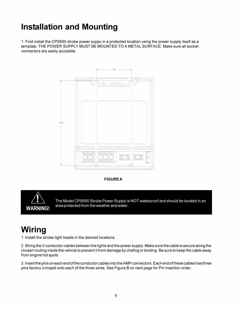
Installation and Mounting
1. First install the CPS690 strobe power suppy in a protected location using the power supply itself as atemplate. THE POWER SUPPLY MUST BE MOUNTED TO A METAL SURFACE. Make sure all socketconnectors are easily accesible.
Wiring1. Install the strobe light heads in the desired locations.
2. String the 3-conductor cables between the lights and the power supply. Make sure the cable is secure along thechosen routing inside the vehicle to prevent it from damage by chafing or binding. Be sure to keep the cable awayfrom engine hot spots.
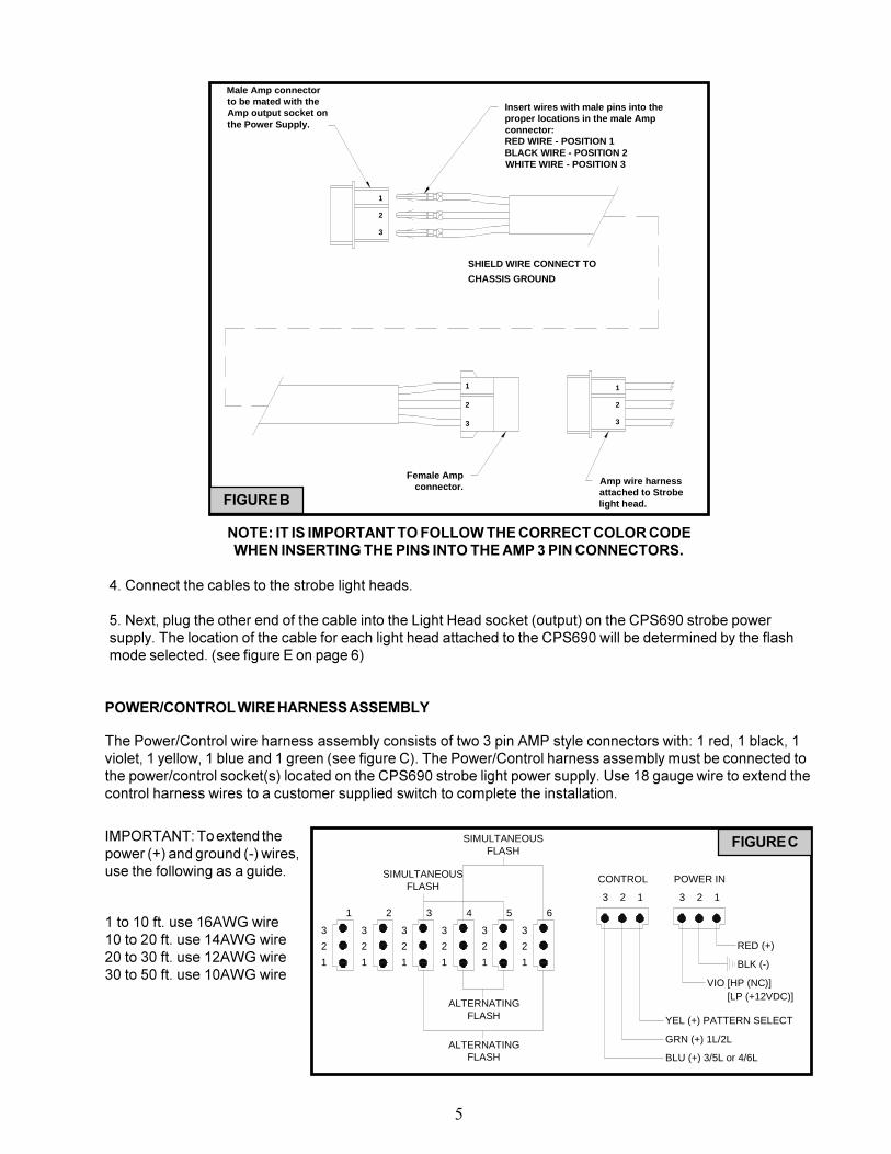
3. Insert the pins on each end of the conductor cables into the AMP connectors. Each end of these cables has threepins factory crimped onto each of the three wires. See Figure B on next page for Pin Insertion order.
�����
�����
The Model CPS690 Strobe Power Supply is NOT waterproof and should be located in anarea protected from the weather and water.
!WARNING!
FIGURE A
5
NOTE: IT IS IMPORTANT TO FOLLOW THE CORRECT COLOR CODEWHEN INSERTING THE PINS INTO THE AMP 3 PIN CONNECTORS.
4. Connect the cables to the strobe light heads.
5. Next, plug the other end of the cable into the Light Head socket (output) on the CPS690 strobe powersupply. The location of the cable for each light head attached to the CPS690 will be determined by the flashmode selected. (see figure E on page 6)
POWER/CONTROL WIRE HARNESS ASSEMBLY
The Power/Control wire harness assembly consists of two 3 pin AMP style connectors with: 1 red, 1 black, 1violet, 1 yellow, 1 blue and 1 green (see figure C). The Power/Control harness assembly must be connected tothe power/control socket(s) located on the CPS690 strobe light power supply. Use 18 gauge wire to extend thecontrol harness wires to a customer supplied switch to complete the installation.
IMPORTANT: To extend thepower (+) and ground (-) wires,use the following as a guide.
1 to 10 ft. use 16AWG wire10 to 20 ft. use 14AWG wire20 to 30 ft. use 12AWG wire30 to 50 ft. use 10AWG wire
3
2
1
2
1
3
2
1
3
2
1
3
2
1
3
2
1
3
3 12 123
SIMULTANEOUSFLASH
SIMULTANEOUSFLASH
ALTERNATINGFLASH
ALTERNATINGFLASH
RED (+)
BLK (-)
VIO [HP (NC)]
CONTROL POWER IN
YEL (+) PATTERN SELECT
GRN (+) 1L/2L
BLU (+) 3/5L or 4/6L
1 2 3 4 5 6
[LP (+12VDC)]
FIGURE C
SHIELD WIRE CONNECT TO
CHASSIS GROUND
Male Amp connectorto be mated with theAmp output socket onthe Power Supply.
3
2
1
2
3
1
Amp wire harnessattached to Strobelight head.
Female Ampconnector.
3
1
2
Insert wires with male pins into theproper locations in the male Amp connector:RED WIRE - POSITION 1BLACK WIRE - POSITION 2WHITE WIRE - POSITION 3
FIGURE B
6
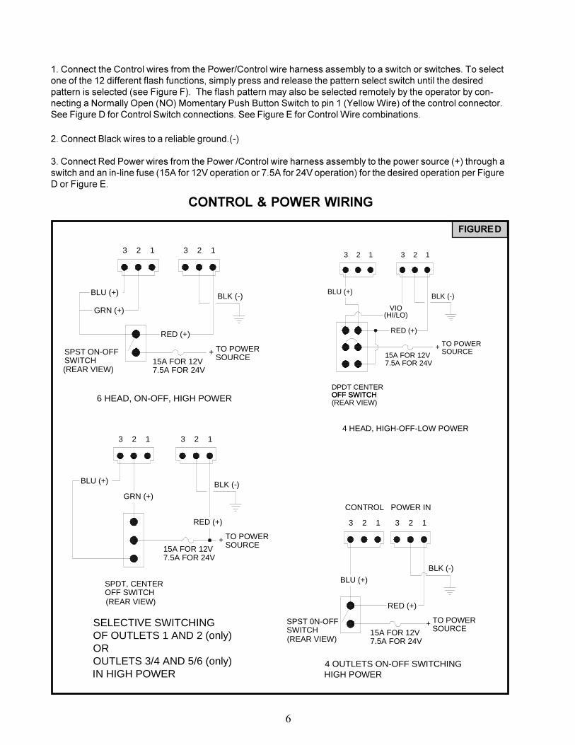
1. Connect the Control wires from the Power/Control wire harness assembly to a switch or switches. To selectone of the 12 different flash functions, simply press and release the pattern select switch until the desiredpattern is selected (see Figure F). The flash pattern may also be selected remotely by the operator by con-necting a Normally Open (NO) Momentary Push Button Switch to pin 1 (Yellow Wire) of the control connector.See Figure D for Control Switch connections. See Figure E for Control Wire combinations.
2. Connect Black wires to a reliable ground.(-)
3. Connect Red Power wires from the Power /Control wire harness assembly to the power source (+) through aswitch and an in-line fuse (15A for 12V operation or 7.5A for 24V operation) for the desired operation per FigureD or Figure E.
CONTROL & POWER WIRING
FIGURE D
SELECTIVE SWITCHING OF OUTLETS 1 AND 2 (only)OROUTLETS 3/4 AND 5/6 (only)IN HIGH POWER
15A FOR 12V7.5A FOR 24V
OFF SWITCHSPDT, CENTER
+
RED (+)
TO POWERSOURCE
BLU (+)
GRN (+)
123
BLK (-)
123
(REAR VIEW)
4 OUTLETS ON-OFF SWITCHINGHIGH POWER
SPST 0N-OFFSWITCH
7.5A FOR 24V15A FOR 12V
TO POWERSOURCE
+
1
BLU (+)
RED (+)
23 1 3 2
BLK (-)
CONTROL POWER IN
(REAR VIEW)
123 23
BLK (-)
RED (+)
1
GRN (+)
BLU (+)
SPST ON-OFFSWITCH 15A FOR 12V
7.5A FOR 24V
+SOURCETO POWER
6 HEAD, ON-OFF, HIGH POWER
(REAR VIEW)
DPDT CENTER
BLU (+)
OFF SWITCH
RED (+)
7.5A FOR 24V15A FOR 12V
TO POWER+SOURCE
3 2 1 3 2
BLK (-)
1
VIO(HI/LO)
4 HEAD, HIGH-OFF-LOW POWER
OFF SWITCH(REAR VIEW)
4 OR 6 OUTLETS ON-OFF HIGH POWER
BLU (+)
SPDT, CENTEROFF SWITCH
7.5A FOR 24V15A FOR 12V
TO POWERSOURCE
+
1
GRN (+)
RED (+)
23 1 3 2
BLK (-)
CUSTOMERSUPPLIED DIODE 1N4700 OR EQUIVALENT
CONTROL POWER IN
(REAR VIEW)
FIGURE E
7
8
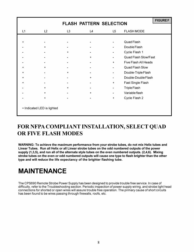
FOR NFPA COMPLIANT INSTALLATION, SELECT QUADOR FIVE FLASH MODES
WARNING: To achieve the maximum performance from your strobe tubes, do not mix Helix tubes andLinear Tubes. Run all Helix or all Linear strobe tubes on the odd numbered outputs of the powersupply (1,3,5), and run all of the alternate style tubes on the even numbered outputs. (2,4,6). Mixingstrobe tubes on the even or odd numbered outputs will cause one type to flash brighter than the othertype and will reduce the life expectancy of the brighter flashing tube.
MAINTENANCE
The CPS690 Remote Strobe Power Supply has been designed to provide trouble free service. In case ofdifficulty, refer to the Troubleshooting section. Periodic inspection of power supply wiring, and strobe light headconnections for shorted or open wires will assure trouble free operation. The primary cause of short circuitshas been found to be wires passing through firewalls, roofs, etc.
FIGURE FFLASH PATTERN SELECTION
L1 L2 L3 L4 L5 FLASH MODE
* - - - - Quad Flash
- * - - - Double Flash
- - * - - Cycle Flash 1
- - - * - Quad Flash Slow/Fast
- - - - * Five Flash All Heads
* * - - - Quad Flash Slow
* - * - - Double-Triple Flash
* - - * - Double-Double Flash
* - - - * Fast Single Flash
- * * - - Triple Flash
- * - * - Variable flash
- * - - * Cycle Flash 2
* Indicated LED is lighted
TROUBLESHOOTING GUIDE
9
TroubleshootingNOTE: DO NOT TAMPER WITH THE POWER SUPPLY. THIS UNIT IS SOLD AS A COMPLETEMODULE, AND IS NOT DESIGNED FOR FIELD REPAIR. REMOVING THE TOP CASE CAN RESULTIN ELECTRIC SHOCK AND WILL VOID THE WARRANTY.
All CPS690 Remote Strobe Power Supply units are thoroughly tested before shipment. However,should you encounter a problem during installation or during the life of the product, refer to the guidebelow for information on troubleshooting. In most cases problems that occur will be related either to thepower/control wiring, or to the strobe light head cables that connect them to the strobe power supply.In the event that the strobe power supply is at fault return the unit to the factory for service.
External fuse blows
Light heads do not fire
Incorrect flash pattern
Flash patterns changecontinuously
1. Power input wires reversed2. Power supply failure3. Incorrect fuse size
1. Cable connections loose atpower supply or light head2. Cable to light heads dam-aged and shorting to chassis
1. Control harness wiring andor switches not connectedproperly2. Light heads plugged intowrong outlet on the powersupply
1. Power Supply is in CYCLEFLASH mode. Proper opera-tion.
1. Check power connections2. Return for service3. Replace with a 15A
1. Check all connections
2. Isolate damaged cable by disconnectingand reconnecting outputs one at a time.Repair or replace the damaged cable.(When other heads come back on the onethat is disconnected is the shorted line.)
WARRANTYThis product was tested and found to be operational at the time of manufacture. Provided this
product is installed and operated in accordance with the manufacturer's recommendations, PublicSafety Equipment guarantees the CPS690 for a period of 5 years from the date of purchase ordelivery, whichever is later. Units demonstrated to be defective within the warranty period will berepaired or replaced at the factory service center at no cost.
Use of a lamp or other electrical load of a wattage higher than installed or recommended bythe factory, or use of inappropriate or inadequate wiring or circuit protection causes this warranty tobecome void. Failure or destruction of the product resulting from abuse or unusual use and/oraccidents is not covered by this warranty. Use of non-PSE components and assemblies maycause damage to the system and/or personal injury, and voids all warranties on PSE systems andcomponents.
PSE shall in no way be liable for other damages including consequential, indirect or specialdamages whether loss is due to negligence or breach of warranty.PSE MAKES NO OTHER EXPRESS OR IMPLIED WARRANTY INCLUDING, WITHOUT LIMITATION,WARRANTIES OF FITNESS OR MERCHANTABILITY, WITH RESPECT TO THIS PRODUCT.
PRODUCT RETURNSIn order to provide you with faster service, if you are going to return a product for repair or
replacement*, please contact our factory to obtain a Return Goods Authorization Number (RGAnumber) before you ship the product to PSE. Write the RGA number clearly on the package nearthe mailing label. Be sure you use sufficient packing materials to avoid damage to the productbeing returned while in transit.
*PSE reserves the right to repair or replace product at its discretion. PSE assumes no responsibility orliability for expenses incurred for the removal and/or reinstallation of products requiring service and/or repair.
NEED HELP? Call our Technical Assistance Hotline - (314) 996-2800