PrefaceThese operating and maintenance instructions describe the safe operation of the CR7 soil compactor. Please read thisoperation manual and familiarize yourself with all details of your soil compactor before operating the machine for the firsttime. Carefully follow all instructions and always carry out the described operations in the indicated order.
Please refer to the following page for the General Safety Instructions.
We reserve the right to modifiy our equipment without prior notice.
In chapter 1, the soil compactor is briefly described to provide you with a good overview on the location of the individualassembly groups and their functions. Chapter 2 describes how to put the soil compactor into and out of operation and howto work with the machine.
In chapter 3, you will find a survey on and a description of the required service work. Chapter 4 contains instructions fortrouble shooting by the operator. Chapter 5 describes how to preserve the soil compactor for an extended storage, e.g.during the winter season.
We placed a great emphasis on a user-friendly lay-out with clear pictorial and textual information. In the text, you will findfigures in brackets which point out to illustrations, whereby the first figure indicates the figure number and the second one- separated by a dash - indicates the item number on the corresponding illustration.
Example 1: (2/1) means figure 2, item 1
Example 2: (2/3,6) means figure 2, item 3 and item 6
Important information for the operator and service personnel is highlighted by pictograms.
Indicates important information and hints which must be followed by the operator and service personnel.
Indicates working and operating methods requiring in addition the observance of all applicable environmentprotection and waste disposal regulations.
Indicates working and operating methods which must be precisely followed in order to prevent the soilcompactor from being damaged or deteriorated.
Indicates working and operating methods which must be precisely followed in order to avert direct danger topersons.
For further information, please contact your authorized WEBER distributor or one of the addresses on the last page.
4 CR7
General Safety InstructionsGeneral
All safety notes (see also explanations of the pictogram meanings in the preface) must be read and observed (any lack ofclarity must be dispelled before the soil compactor is put into operation), because otherwise the use of the machine may
* constitute a risk to life and limb of the user
* impair the machine and other valuable property.
In addition to these operating instructions and the mandatory accident prevention regulations in the country of use and onthe operating site, the generally accepted technical standards for safe and professional work must be also observed.
Designated Use
Soil compactors are only allowed to be operated in accordance with their designated use, whereby the operating andmaintenance instructions, the generally accepted safety and traffic rules and the regulations of the individual countries of usemust be followed.
The soil compactor has been exclusively designed for the compaction of
- sand
- gravel
- crushed aggregates
- semi-cohesive mixed material
- concrete block pavement.
Any other use of the soil compactor is considered contrary to its designated use. The company operating the soil compactorbears the sole responsibility for any misuse of the machine.
Driving Permission
Only trustworthy persons, who are aged at least 18 years, are allowed to handle soil compactors. They must be properly trainedin the operation and maintenance of the soil compactor by the employer or his authorized representative.
Protective Equipment
When operating the soil compactor described in this operation and maintenance manual, the noise level at the operator's earmay exceed 90 dB(A). The German noise protection regulations (VBG 121) require the operator to wear personal earprotectors in case of noise levels of 90 dB(A) and more.
Additionally, a safety helmet and safety shoes belong to the protective equipment.
General Safety Instructions ...................................................................................................................................4
2 Operation ..............................................................................................................................................................102.1 Safety Precautions for the Operation .................................................................................................................102.2 Transport ............................................................................................................................................................... 112.2.1 Loading by Crane ................................................................................................................................................. 112.3 Commissioning .................................................................................................................................................... 112.4 Pre-Start Work ......................................................................................................................................................122.4.1 Checking the Fuel Level ......................................................................................................................................122.4.2 Checking the Engine Oil Level ............................................................................................................................132.4.3 Fitting the Damper Plate ......................................................................................................................................142.4.4 Fitting/Detaching the Extension Plates ..............................................................................................................142.5 Starting ..................................................................................................................................................................152.6 Compaction Work .................................................................................................................................................162.7 Putting the Soil Compactor out of Operation.....................................................................................................162.7.1 Stopping ................................................................................................................................................................17
3 Maintenance .........................................................................................................................................................183.1 Safety Precautions for Maintenance Work .........................................................................................................183.2 Maintenance Survey .............................................................................................................................................193.2.1 Routine Maintenance ...........................................................................................................................................193.3 Description of the Maintenance Work ................................................................................................................203.3.1 Changing the Engine Oil ......................................................................................................................................203.3.1.1 Cleaning the Engine Oil Filter .............................................................................................................................213.3.2 Cleaning/Replacing the Air Filter Cartridge ........................................................................................................223.3.3 Replacing the Fuel Filter ......................................................................................................................................233.3.4 Checking the Condition and Tension of the Vibrator V-Belt .............................................................................243.3.5 Replacing the V-Belt .............................................................................................................................................243.3.6 Changing the Vibrator Oil ....................................................................................................................................253.3.7 Hydraulic Control .................................................................................................................................................263.4 Consumables and Quantities ..............................................................................................................................27
4 Malfunctions During Operation ...........................................................................................................................284.1 General ..................................................................................................................................................................284.2 Trouble Shooting ..................................................................................................................................................294.3 Repair and Replacement Work ............................................................................................................................304.3.1 Replacing the Battery...........................................................................................................................................304.3.2 Replacing the Fuse ..............................................................................................................................................30
5 Preserving the Machine .......................................................................................................................................315.1 Preservation Measures ........................................................................................................................................31
8 Engine bracket9 Vibrator10 V-belt guard11 Spring bar (not shown)12 Engine speed adjusting lever13 Vulkollan plate (not shown)14 Extension plates
7CR7
1.2 Machine Description
The CR 7 soil compactors are machines of the walk-behind type used for compaction work in road construction andlandscape applications.
Propulsion
The CR 7 soil compactor is driven by a Lombardini Diesel engine.
Important!
Please refer to paragraph 1.3 (Specifications) for the performance details of the engine and the wholemachine.
Function
The engine (1/1) drives the vibrator via a V-belt. The vibrator is screwed down to the base plate (1/6) and sets itvibrating. The vibrating base plate performs the vibration work and travelling motion.
Accessories
A damper plate (2.4.3) and extension plates (2.4.4) are available as optional extras.
Operation
The soil compactor is started by means of an electric starter (1/5).
The soil compactor is steered by means of the handle (1/3) holding the engine speed adjusting lever (1/12) and thedrive lever (1/2) to control the direction of travel and the infinitely variable driving speed. The spring bar (1/11) allowsto fix the handle in vertical position during work breaks and transports.
8 CR7
1.3 Specifications CR 7
Weight
Operating weight according to CECE in kg 450 474
Dimensions
Overall length (in mm) 1740 1740
Width with extension plates (in mm) 600 800
Height with handle folded down (in mm) 1135 1135
Base plate length (contact area in mm) 440 440
Propulsion
Engine manufacturer
Type
Maximum output according to DIN 70020 (in kW (HP))
Type of combustion
Operating speed
Driving speed (dependent on soil conditions (in m/min) 24 19
Gradeability (dependent on soil conditions, in %) 30 30
Depth compaction (in cm) 70 70
Performance (in m2/h) 864 912
Vibration
System
Mode of driving
Frequency (in Hz)
Centrifugal force (in kN)
65
60
4-stroke Diesel
2800
Two-shaft vibrator
Mechanical
CR 7
Lombardini
15LD440
8,1 (11,0)
9CR7
1 2Weber Maschinentechnik GmbH
Typ Masch.-Nr.
Betriebsgewicht Baujahr
Postfach 215357329 Bad Laasphe-Rückershausen
43
CR 7
Noise and Vibration Data*
Sound pressure level LPA (at the operator's place, according to 2000/14/EG, in dB(A))
98
Sound power level LWA (according to 2000/14/EG, in dB(A))
109
Hand/arm vibration (weighted root mean square acceleration, at the handle, determined according to 2002/44/EG, Part 1, in m/s² )
5,3 * 4,4 **
3 TYPE
.........................................
4 ENGINE/SERIAL No.
.........................................
1 MACHINE NO.
.........................................
2 YEAR OF CONSTRUCTION
.........................................
* 600 mm** 800 mm
MADE IN ITALY
* The indicated noise and vibration data were determined with the engine at nominal speed and the vibrationsystem turned on, 2000/14/EG. During operation, these data may vary according to the specific conditionsprevailing on the job site.
10 CR7
2 Operation
2.1 Safety Precautions for the Operation
Safety and protection devicesBefore every shift, the operator must check the operativeness of all controls and safety elements as well as the properinstallation of all protection devices. The soil compactor is only allowed to be operated with all protection devices inplace. The control's functionality is not allowed to be impaired or neutralized.
Before starting the soil compactor, the operator must take his personal noise protection measures. Before starting theengine, check to ensure that the soil compactor cannot slip out of control.
Conduct in Case of FailuresIf defective safety devices or other failures which might affect the safe operation of the soil compactor are ascertained,the supervisor must be informed without delay. In case of malfunctions endangering the unit's operational safety, themachine must be turned off immediately.
Conduct of the Machine OperatorDuring the machine's operation, the operator has to constantly supervise the operational safety of the soil compactor.When running the machine, the operator is not allowed to leave the operating controls of the soil compactor. In addition,he must always have a sufficient visibility on the soil compactor's zone of operation.The operator must be assisted by asecond person if, because of the operating conditions, the visibility on the zone of operation is restricted.
StabilitySoil compactors must be used and operated in a way ensuring their stability. The machine's stability is especiallyendangered on slopes and brinks. Thus, keep clear of slopes and brinks.
Driving and CompactingWhen working on slopes, the operator must always walk on the uphill side. Compaction work on slopes exceeding themaximum gradeability of the soil compactor is prohibited. When working/travelling on slopes, always use extremeprecaution and work directly in uphill or downhill direction.
Moist and loose bases considerably reduce the grip of the soil compactor on slopes. Increased danger ofaccident!
Passing unevennesses or kerbs is only allowed at reduced speed. In addition, the soil compactor must be operated in away excluding any risk of injury caused by the handle swinging towards the operator.
Exhaust Precautions
Never inhale exhaust gasses. They contain carbon monoxide, a colorless, oderless and extremely dangerous gaswhich can cause unconsciousness or death. Never operate the engine inddors or in a poorly ventilated area, suchas tunnerl, cave, etc. Exercise extreme care when operating the engine near people or animals. Keep the exhaustpipe free of foreign objects.
11CR7
- Put the soil compactor out of operation as described inparagraph 2.7.
- Lock the handle (2/1) by means of the spring bar (2/2).
Danger!
Never use the handle (2/1) for lifting the machine bycrane. The machine may overturn!!
Danger!
Only use a lifting tackle and a crane of a sufficientbearing capacity.
Danger!
Do not enter the zone under the suspended load.
2.2 Transport
Figure 2
Figure 2 a
1
2
1
Short distances on the job site can be covered by the soilcompactor in accordance with paragraph 2.6.
For long distances, however, the compactor can be lifted onan appropriate transport vehicle (truck, trailer) by means of acrane.
2.2.1Loading by Crane
2.3 CommissioningCaution!
For commissioning, only carry out the pre-start work described in paragraph 2.4.
Keep to the initial maintenance intervals (refer to paragraph 3.2.1).
- Put the crane hook into the protection frame (2a/1).
12 CR7
- Put the soil compactor out of operation as described inparagraph 2.7.
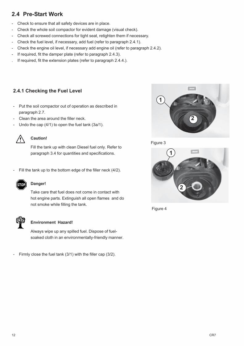
- Clean the area around the filler neck.- Undo the cap (4/1) to open the fuel tank (3a/1).
Caution!
Fill the tank up with clean Diesel fuel only. Refer toparagraph 3.4 for quantities and specifications.
- Fill the tank up to the bottom edge of the filler neck (4/2).
Danger!
Take care that fuel does not come in contact withhot engine parts. Extinguish all open flames and donot smoke while filling the tank.
Environment Hazard!
Always wipe up any spilled fuel. Dispose of fuel-soaked cloth in an environmentally-friendly manner.
- Firmly close the fuel tank (3/1) with the filler cap (3/2).
Figure 4
2
Figure 3
2.4 Pre-Start Work- Check to ensure that all safety devices are in place.- Check the whole soil compactor for evident damage (visual check).- Check all screwed connections for tight seat, retighten them if necessary.- Check the fuel level, if necessary, add fuel (refer to paragraph 2.4.1).- Check the engine oil level, if necessary add engine oil (refer to paragraph 2.4.2).- If required, fit the damper plate (refer to paragraph 2.4.3).. If required, fit the extension plates (refer to paragraph 2.4.4.).
2.4.1 Checking the Fuel Level
2
1
1
13CR7
Caution!
The engine oil level must be checked with the soilcompactor standing horizontally on the ground.
- Pull out the oil dipstick (5/1), wipe it off with a clean, non-fluffing cloth and insert it again.
Caution!
-Screw the oil dipstick (5/1) down.-Undo the oil dipstick once again.
Caution!
The oil level must reach up to the top mark(5/max).
- If required, add engine oil according to paragraph 3.3.1(refer to paragraph 3.4 for quantities and specifications).
- Firmly screw the oil dipstick down.
Figure 5
1
max.
2.4.2 Checking the Engine Oil Level
14 CR7
- Put the soil compactor out of operation as described in paragraph2.7.
- Lift the soil compactor by means of a crane as described inparagraph 2.2.1.
- Put the damper plate beneath the machine.
Caution!Do not enter the zone under the suspended load. - Risk ofinjury!
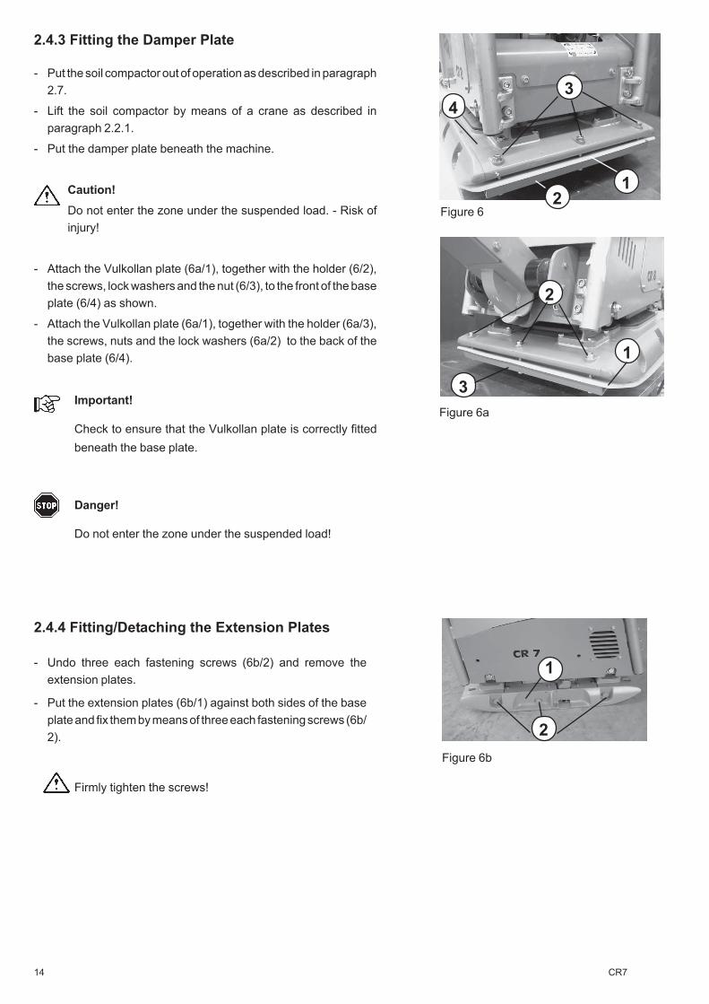
- Attach the Vulkollan plate (6a/1), together with the holder (6/2),the screws, lock washers and the nut (6/3), to the front of the baseplate (6/4) as shown.
- Attach the Vulkollan plate (6a/1), together with the holder (6a/3),the screws, nuts and the lock washers (6a/2) to the back of thebase plate (6/4).
Important!
Check to ensure that the Vulkollan plate is correctly fittedbeneath the base plate.
Danger!
Do not enter the zone under the suspended load!
Figure 6
Figure 6a
2.4.4 Fitting/Detaching the Extension Plates
- Undo three each fastening screws (6b/2) and remove theextension plates.
- Put the extension plates (6b/1) against both sides of the baseplate and fix them by means of three each fastening screws (6b/2).
Firmly tighten the screws!
1
34
2
3
1
2
Figure 6b
1
2.4.3 Fitting the Damper Plate
2
15CR7
In case of any irregularity, turn off the engine immediately, localize and repair the malfunction.Let the engine idle for some minutes.
In case of ambient temperatures of 5 degrees C below zero or less, the starting procedure must be carried out in accordance with the operation manual of the engine manufacturer.
Caution!
If the ignition key does not automatically return into position 1, put the machine out of operation - risk of starter damage because of starter working during machine operation.
Figure 7
1
1
23
45
6
7
2.5 Starting
Danger!
Before starting the machine, always ensure that nobody is inthe danger area of the soil compactor and that all protectivedevices are properly in place.
When starting the soil compactor in closed premises, alwaysensure a proper ventilation - danger of poisoning.
Caution!
Never use starting aid sprays!
- Put the engine speed adjusting lever (7/1) into the full speed position.
- Put the ignition key (8/1) into the lock and turn it into position 1.
- Turn the ignition key (8/1) into position 2.
- Release the ignition key as soon as the engine starts.
Important!
The ignition key must automatically return into position 1 andmust remain in this position during operation. The alternatorcharge pilot lamp (8/3) and the oil pressure pilot lamp (8/4)must go out immediately after starting.
Caution!
The pilot lamp (8/2) lights up to indicate the engine'soperation.As long as the ingition is switched on, the hourmeter(8/7) records the working hours performed.
The symbols (8/5) and (8/6)are not assigned to a function.
Figure 8
Important!
16 CR7
2.6 Compaction Work
- Put the soil compactor into operation (refer to paragraph 2.5).As soon as the engine reaches its operating temperature:
- push the engine speed adjusting lever (9/1) into the full speed position.
Caution!
Compaction work is only allowed at full engine speed, otherwise thecentrifugal clutch may slip and cause increased wear.
Important!
As soon as the centrifugal clutch achieves the cutting-in speed, thevibrator is automatically turned on.
Danger!
If obstructions (such as walls or trenches) are encountered, take carethat persons do not get crushed and that the machine does not slip outof control.
Warning!
During work breaks, even if they are short, the soil compactor must beput out of operation (refer to 2.7).
- Steer the soil compactor with the handle (9/2) into the desired direction.
2.7 Putting the Soil Compactor Out of Operation
Before work breaks and at the end of every day’s shift, the soil compactormust be parked on a stable base which should be as horizontal as possible.
Warning!
If the soil compactor causes an obstruction when being parked,precautionary measures must be taken in order to make the machinevisible. If the machine is parked on traffic roads, the safety precautionsrequired by the traffic regulations must be additionally observed.
Caution!
Never stop the engine while it is running at full speed, but let the engineidle for some minutes.
21
Figure 9
17CR7
2.7.1 Stopping
��
���
1
1
Figure 10
Figure11
- Push the speed adjusting lever (10/1) to the back and let the engineidle for some minutes.
- Turn the ignition key (11/1) from position "1" back in-
to position "0".
- Take out the ignition key.
18 CR7
3 Maintenance3.1 Safety Precautions for Maintenance Work
ChecksDependent upon the operating conditions, soil compactors must be made subject to an expert's check for operationalsafety as required, but at least once a year. The inspection results must be recorded in writing and kept at least until thenext inspection.
Service WorkService work is only allowed to be done when the drives are stopped. Exceptions are only allowed if work can be done withrunning drives only. In addition, the soil compactor must be secured against unintentional movements.
Drained consumables must be caught and stored in an appropriate receptacle and disposed off according to therelevant environmental protection regulations.
Prior to any work on parts which are not protected, the engine must be secured against unintentional starting.After completion of service work, all protective devices must be properly installed again.
Modifications and RetrofittingsFor safety reasons, any modifications and retrofittings made on the soil compactor without the manufacturer'sauthorization, are prohibited. Damage resulting from modifications or retrofittings is excluded from the manufacturer'sliability. Only use genuine WEBER spare parts to ensure a safe and reliable operation.
Safety Precautions Required by the Engine ManufacturerPlease refer to the annexed operation manual of the engine manufacturer Lombardini for a detailed description of themaintenance work to be done on the engine.
19CR7
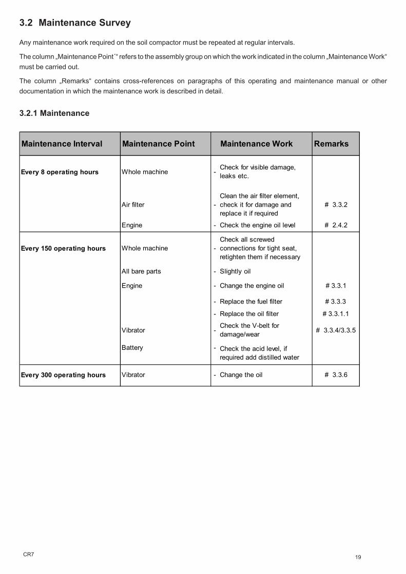
3.2 Maintenance Survey
3.2.1 Maintenance
Any maintenance work required on the soil compactor must be repeated at regular intervals.
The column „Maintenance Point´“ refers to the assembly group on which the work indicated in the column „Maintenance Work“must be carried out.
The column „Remarks“ contains cross-references on paragraphs of this operating and maintenance manual or otherdocumentation in which the maintenance work is described in detail.
Maintenance Interval Maintenance Point Maintenance Work Remarks
Every 8 operating hours Whole machine -Check for visible damage, leaks etc.
Air filter -Clean the air filter element, check it for damage and replace it if required
# 3.3.2
Engine - Check the engine oil level # 2.4.2
Every 150 operating hours Whole machine -Check all screwed connections for tight seat, retighten them if necessary
All bare parts - Slightly oil
Engine - Change the engine oil # 3.3.1
- Replace the fuel filter # 3.3.3
- Replace the oil filter # 3.3.1.1
Vibrator -Check the V-belt for damage/wear # 3.3.4/3.3.5
Battery -
Every 300 operating hours Vibrator - Change the oil # 3.3.6
Check the acid level, if required add distilled water
20 CR7
- Put the soil compactor out of operation as described in paragraph2.7.
Caution!
Drain off the engine oil at operating temperature and with thesoil compactor in horizontal position only.
- Put a drain pan under the outlet.
Environment Hazard!
Choose a drain pan having a sufficient capacity to catch all theused oil. Do not let used oil run into the soil. Dispose of thecollected used oil in an environmentally-friendly manner (acc.to statutory pollution control regulations).
Wipe up any oil residues and dispose of the oil-soaked cloth inan environmentally-friendly manner.
Danger!
Danger of scalding because of hot oil.
- Undo the screws (12/2) to remove the cover (12/1).- Pull out the oil dipstick (13/1).- Undo the protective cap (13/2).- Screw the oil drain hose (14/1) onto the drain valve (14/2) and
completely drain the engine oil.
Important!Screwing the drain hose down opens the drain valve - oilescapes!
- Undo the oil drain hose (14/1).- Put the protective cap (13/2) onto the drain valve (13/3).- Top up with engine oil according to the quantity chart (3.4).- Check the oil quantity by means of the dipstick (13/1) (refer to
paragraph 2.4.1).- Screw the dipstick (13/1) down.
Caution!Make a short trial run and check tightness!
3.3 Description of the Maintenance Work3.3.1 Changing the Engine Oil
Figure 12
Figure 13
2
Figure 14
1
2
1
1
3
2
21CR7
3.3.1.1 Cleaning the Engine Oil Filter
Figure 15
Figure 16
1
- Put the soil compactor out of operation as describedin paragraph 2.7.
- Drain the engine oil according to paragraph 3.3.1.
- Undo the screws (15/1) and remove the lid (15/2)of the filter body.
- Pull the oil filter (16/1) out of the crankcase andreplace it by a new oil filter.
- Put the oil filter into the crankcase (16a/1).
- Put the lid (15/2) onto the crankcase and fasten it bymeans of the screws (15/1).
Environment Hazard!
Wipe up any oil and dispose of the oil filter andthe oil-soaked cloth in an environmentally-friendly manner.
- Top up with engine oil according to paragraph 3.3.1.
Caution!
Make a short trial run and check for tightness,if required, retighten the screws.
2
1
1
Figure 16 a
22 CR7
3.3.2 Cleaning/Replacing the Air Filter Cartridge
- Loosen the fastening screw (17/2) and remove the cover (17/1)from the air filter body.
- Pull the air filter element (18/1) out of the air filter body(18/2) andblow or knock it clean.
Caution!
If this procedure does not provide a sufficient cleaning (e. g.because of humid or oily dirt), a new filter element must beused.
- Insert the filter (18/1) again.- Put the cover (17/1) on the air filter body again and firmly close
the body with the screw (17/2).
Figure 17
Figure 18
1
2
1
2
23CR7
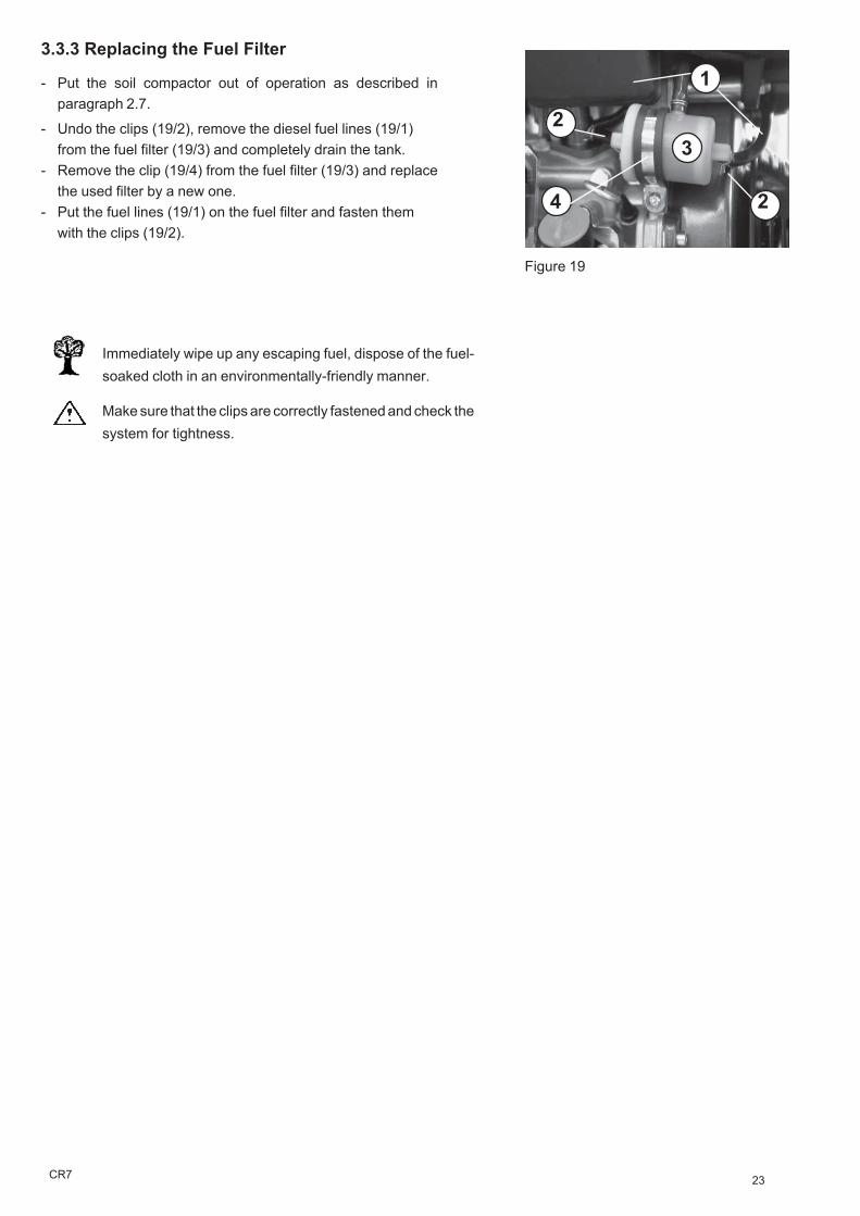
3.3.3 Replacing the Fuel Filter
Figure 19
- Put the soil compactor out of operation as described inparagraph 2.7.
- Undo the clips (19/2), remove the diesel fuel lines (19/1)from the fuel filter (19/3) and completely drain the tank.
- Remove the clip (19/4) from the fuel filter (19/3) and replacethe used filter by a new one.
- Put the fuel lines (19/1) on the fuel filter and fasten themwith the clips (19/2).
Immediately wipe up any escaping fuel, dispose of the fuel-soaked cloth in an environmentally-friendly manner.
Make sure that the clips are correctly fastened and check thesystem for tightness.
2
1
2
3
4
24 CR7
3.3.4Checking the Condition and Tension of the VibratorV-Belt
- Put the soil compactor out of operation as described in paragraph 2.7.- Undo the screws (20/1) to remove the V-belt guard (20/2).- Check the condition of the V-belt (21/1) (cracks, broken out flanks,
wear).- In case of excessive wear, replace the V-belt as described in paragaph
3.3.5.
Caution!
Take care to properly fit the V-belt on the pulleys (belt alignment).
The special centrifugal clutch will tension the V-belt.
3.3.5 Replacing the V-Belt
- Loosen the screws (20/1) and remove the V-belt guard (20/2).- Undo the fastening screw (22/1) and (21/2) of the centrifugal clutch (22/
2) and remove it from the clutch.- Screw a (M20x100) hexagon head cap screw with through-thread into
the centrifugal clutch (22a/1). Remove the clutch from the cone of thedriving engine by means of the (M20x100) screw.
- Remove the screw (22b/3) from the clutch.- At first, mount the V-belt (22b/1) on the pulley of the vibrator and then
on the clutch (22b/2).- Put the centrifugal clutch onto the cone of the driving engine.- Fasten the centrifugal clutch with the screw (21/2) and the disk (21/3).- Fit the V-belt guard (20/2) by means of the screw (20/1).
Caution!
Check to ensure that the V-belt is properly aligned, especially afterrepair work.
Figure 20
Figure 21
Figure 22
2
1
1
2
1
Figure 22a
Figure 22b
1
1
2
2
3
3
Always use a new screw and disk to fasten the centrifugal clutch.
The torque to fasten the centrifugal clutch is 40 Nm.
25CR7
3.3.6 Changing the Vibrator Oil
- Put the soil compactor out of operation as described in paragraph2.7.
Caution!
Change the oil at operating temperature only.
When working on the machine, always protect the soilcompactor against slipping out of control. - Risk of injury -
- Thoroughly clean the oil drain plug (23a/3) and the area around it.- Put an appropriate drain pan (23a/2) beneath the drain outlet.- Remove the oil drain plug (23a/3) from the base plate.- Completely drain the oil.
Caution!
Take care that the contact surfaces of the oil drain/filler plug(23a/3) and of the base plate (23a/1) are clean.
- Tilt the soil compactor.- Top up with gear oil through the oil filler/oil drain opening (23a/3)
(refer to paragraph 3.4 for quantities and specifications).
Environment Hazard!
Dispose of the collected used oil in an environmentally-friendlymanner. Take care that the environment is not polluted by oil.
Figure 23
Figure 23a
1
2
1
26 CR7
3.3.7 Hydraulic Control
The switch head (24/2) is filled with hydraulic oil. Switching is effectedupon actuation of the switch lever (24/1). A hydraulic line connects thereaction end socket (26/1) and the switch head.
Important!In case of switching problems, proceed as follows:
- Remove the oil filler screw (25/2) of the switch head (25/1).- Add hydraulic oil according to the specifications in paragraph 3.4 up to the
middle of the sight glass (25/3). (Handle in vertical position).- Fasten the oil filler screw (25/2).- Bleed the hydraulic system by loosening the bleeding screw (26/2) at the
reaction end housing (26/1).- Firmly tighten the bleeding screw (26/2) again.
Check the oil level once again!
Figure 24
Figure 25
Figure 26
2
1
1
3
max.
1
2
2
27CR7
Assembly Group Consumable QuantitySummer Winter CR 7
Greasing points High-pressure grease (lithium-saponified) as required
according to DIN 51825 - KPF2Battery as requiredDistilled water
API GL-5/GL-4
DieselDiesel according to DIN 51601-DK
or BS2869-A1/A2or STM D975-1D/2D
Fully synthetic gear oil
Fully synthetic gear oil DEXRON II-D-ATF
3.4 Consumables and Quantities
28 CR7
4 Malfunctions During Operation
4.1 General
If a malfunction occurs on the soil compactor, proceed as follows:
- Put the soil compactor out of operation as described in paragraph 2.7.- Determine the source of the malfunction (refer to paragraph 4.2 - Trouble Shooting).- Repair the failure (refer to paragraph 3 (maintenance work) and paragraph 2 (description of the
various controls).
Please refer to the manual of the engine manufacturer with regard to the repair of enginemalfunctions.
The detailed description of the various controls and the references given in the column "Remarks" ofthe maintenance survey chart (paragraph 3) and trouble shooting chart (paragraph 4.2) allow a quickfailure elimination on condition that the given order is precisely kept to when service work is carried out.
Any service work has to be made with appropriate tools and in accordance with the safetyregulations set out in this operating and maintenance manual.
If a problem persists although a component or assembly group has been replaced, repair work has tobe continued with the work described next.
If a failure cannot be repaired although the described service work has been carried out or if a defect isnot described in the operating and maintenance instructions, the failure must be repaired by authorizedservice personnel.
29CR7
4.2 Trouble Shooting
Failure Possible Cause Remedy RemarksSoil compactor does not start
Mistake in operating the unit Perform the starting procedure as described # 2.5
Lack of fuel Check the fuel level # 2.4.1Dirty fuel filter Replace the fuel filter
# 3.3.3
Dirty air filter Clean/replace the air filter cartridge # 3.3.2
No vibration/no or insufficient forward travel
Defective vibrator V-belt Replace the vibrator V-belt
# 3.3.5
Delayed control Air in the hydraulic control system
Bleed the control system# 3.3.7
30 CR7
4.3 Repair and ReplacementWork
4.3.1Replacing the Battery
- Put the soil compactor out of operation as describedin paragraph 2.7.
- Undo the fastening screws (27/1) and remove thebattery cover (27/2).
- Disconnect the cable plug (28/3).
- Disconnect the terminals (28/1).
At first, disconnect the negative terminal.
- Undo the screws (28/2) and take out the battery.
The installation is done in reverse order.
Figure 27
Figure 28
1
2
Figure 29
4.3.2Replacing the Fuse
- Put the soil compactor out of operation as described in paragraph2.7.
- Remove the protective cap (29/1) of the fuse holder (29/2).
- Remove the fuse (30/1) from the fuse holder (30/2).
- Insert a new fuse (30/1) with a rating of 20 A.
1 2
21
1
23
Figure 30
31CR7
5 Preserving the Machine
5.1 Preservation Measures
If the soil compactor is planned to be put out of operation for an extended period of time (approx. 1 ... 6months), e. g. during the winter season, it must be stored in a frost-proof and dry room. Before storing themachine, however, the preservation measures described in paragraph 5.1 must be taken. After the storage,the soil compactor must be put in operation according to paragraph 5.2.
If the soil compactor is to be stored for more than 6 months, additional measures must be taken inaccordance with your WEBER service.
5.2 Removing Machine Preservatives
Assembly Group Measure Remarks
Whole soil compactor - Thoroughly clean
- Check condition, fastenings and tightness
- Have any failures ascertained repaired
All bare parts - Apply a slight film of grease or oil
Fuel tank - Add fuel up to the bottom edge of the filler neck # 2.4.1
Engine - Check the oil level, if required, add oil # 2.4.2
- In the location of storage, put the engine into operation until its operating temperature is achieved.
- Put the engine out of operation # 2.7
Battery -Detach, charge, measure the fluid level, add distilled water if required # 4.3.1
Assembly Group Measure Remarks
Whole soil compactor - Thoroughly clean
- Charge the battery
- Perform pre-start work # 2.4.
6 Addresses, Weber Maschinentechnik GmbH
For problems, questions and further information refer to one of the following addresses: