Page 1
1
Crack Detection in Aluminium 2024-T3 Plates and in
an Airbus A320 Slat-Track using Electrical Crack Gauges
Ioannis PITROPAKIS1, Helge PFEIFFER1, Thomas GESANG2,
Stein JANSSENS3 and Martine WEVERS1
1Katholieke Universiteit Leuven (KULeuven), Department of Metallurgy and Materials Engineering (MTM);
Leuven, Belgium; [email protected] , [email protected] ,
[email protected] 2Fraunhofer Institute for Manufacturing Technology and Applied Materials Research (IFAM), Adhesive Bonding
Technology; Bremen, Germany; [email protected] 3ASCO Industries NV, Test and Development; Zaventem, Belgium; [email protected]
Abstract: Structural health monitoring (SHM) is a valuable tool for the investigation and detection of cracks in
various engineering structures. Due to the rapid growth of the aviation industry, SHM might have an important place
in the field of aeronautics. Appropriate SHM sensors on critical structural components could help to reduce costs by
avoiding unnecessary scheduled inspections and will increase the safety of the monitored structures. In this paper,
tests on crack gauges made from conductive material are reported. The gauges were mounted on aluminium 2024-T3
plates and on an Airbus A320 slat-track. The aluminium plates along with the A320 slat-track are consecutively
painted with layers of primer and coating according to the manufacturer standards. The basic concept of crack
detection by the gauges is the interruption of the electrical conductivity by fatigue cracks. The gauges are embedded
between the layers of primer and coating in order to be protected and insulated. Results obtained from resistance
measurements showed that these crack gauges could detect cracks at a relatively early stage.
Keywords: structural health monitoring, crack gauges, slat-track, aluminium 2024-T3, fatigue testing
1. Introduction
In every aircraft, there are critical areas that are subjected to high fatigue loads. These critical
areas can be found in various structural parts of an aircraft. They are characterized as high stress
concentration points and need to be monitored in order to prevent a possible failure when small
cracks are initiated from the stress concentrations. Maintenance departments of airlines are
concerned about these problems. A famous example is the recent fatigue crack appearance in the
wing area of Airbus A380 from Qantas [1]. Structural health monitoring (SHM) is considered as
one of the most promising technologies that can be used for early detection of cracks and prevent
an oncoming critical damage [2].
In this study, aluminium alloy 2024-T3 plates and a slat-track from Airbus A320 were used for
crack detection. In general, slat-tracks in the form that they are manufactured today have not
shown so far any significant problem that has been reported. Nevertheless, major slat-track and
aircrafts manufacturers show a great interest in structural health monitoring of these components
since new materials are considered and safety is always a major issue.
The last years, research has been conducted regarding SHM on slat-track related structures
investigating fatigue and vibration loads that lead to structural damage [3, 4, 5]. A method for
crack monitoring that could be applied on slat-tracks is using ultrasonic surface waves that are
propagated through wedged-shaped sensors [6, 7, 8, 9]. Unfortunately, this method was not
Page 2
2
feasible due to the limited space on the mounted slat-track preventing attachment of the sensors
when racks inside the slat track were present. Another method for crack detection on slat-tracks
used flat piezoelectric transducers actuating different acoustic modes, including bulk waves and
surface waves [10]. This method however provided rather complex data requiring advanced data
analysis. On the other hand, crack gauges and the interruption of the electrical conductivity can
be an efficient, simple and effective method for crack monitoring. Additionally, the equipment
needed for data acquisition can be limited to a simple multimeter and the results obtained are
instant and straightforward. The interest on permanent crack gauges as a SHM system is reflected
by the ongoing research in European projects, such as the Aircraft Integrated Structural Health
Assessment (AISHA) II and the Cooperative Hybrid Objects Sensor Networks (CHOSeN) from
the seventh framework programme funded by the European Union [11, 12].
There are already commercially available crack propagation gauges for the detection of cracks.
These crack propagating gauges are consisting of very thin flat metal stripes that are attached at
critical areas. When a crack propagates through the gauge, each time the crack breaks a stripe of
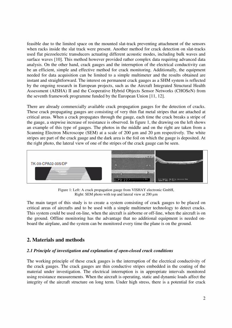
the gauge, a stepwise increase of resistance is observed. In figure 1, the drawing on the left shows
an example of this type of gauges. The photos in the middle and on the right are taken from a
Scanning Electron Microscope (SEM) at a scale of 200 µm and 20 µm respectively. The white
stripes are part of the crack gauge and the dark area is the foil on which the gauge is deposited. At
the right photo, the lateral view of one of the stripes of the crack gauge can be seen.
Figure 1: Left: A crack propagation gauge from VISHAY electronic GmbH,
Right: SEM photo with top and lateral view at 200 µm
The main target of this study is to create a system consisting of crack gauges to be placed on
critical areas of aircrafts and to be used with a simple multimeter technology to detect cracks.
This system could be used on-line, when the aircraft is airborne or off-line, when the aircraft is on
the ground. Offline monitoring has the advantage that no additional equipment is needed on-
board the airplane, and the system can be monitored every time the plane is on the ground.
2. Materials and methods
2.1 Principle of investigation and explanation of open-closed crack conditions
The working principle of these crack gauges is the interruption of the electrical conductivity of
the crack gauges. The crack gauges are thin conductive stripes embedded in the coating of the
material under investigation. The electrical interruption is in appropriate intervals monitored
using resistance measurements. When the aircraft is operating, static and dynamic loads affect the
integrity of the aircraft structure on long term. Under high stress, there is a potential for crack
Page 3
3
formation, and if a crack is present, it will open and close during the load cycles. At the crack
position, tensile as well as compression forces therefore might be present. Without load, it is
possible that the crack cannot be detected by visual inspection, and even ultrasonic methods will
provide wrong read outs due to the change of stress direction, e.g. pressurized cabin or fuselage.
Figure 2: A large crack (30 mm each side) that interrupts the electrical conductivity of the embedded gauges
It is very important for the engineers to be able to monitor and detect cracks even if the cracks are
not apparent. This can happen because the crack might be microscopically open but due to
compressive stresses, it can close again and be very difficult to detect. Therefore, it is important
to have a SHM system that can detect cracks irrespective whether the crack is open or closed.
Because every part has its damage tolerance in crack size, this open and closed crack condition of
the crack is vital to be taken into consideration in order to avoid sudden changes in crack growth.
2.2 Parts under investigation
In this study, the parts investigated are thin aluminium 2024-T3 alloy plates and an Airbus A320
slat-track. In the 2024-T3 plate, the crack growth was monitored by crack gauges and in the A320
slat-track the performance of the electrical gauge was investigated with an existing artificial
crack. Figure 3 shows the parts investigated.
Figure 3: Parts tested: an Aluminium alloy 2024-T3 plate (in the front) and a A320 slat-track (in the back)
The sheets have dimensions 300 mm (length), 80 mm (width), 1 mm (thickness) and are made of
the aluminium alloy 2024-T3, which is widely used in aerospace applications. It is a light
material with high ultimate tensile strength (483 MPa), high tensile yield strength (345 MPa) and
is used to support sheet applications on aircraft components such as wings and fuselage parts,
where fatigue is an important driver [13].
Page 4
4
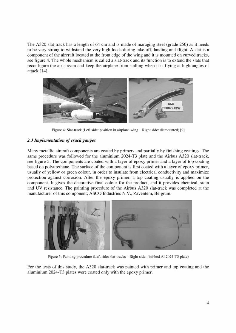
The A320 slat-track has a length of 64 cm and is made of maraging steel (grade 250) as it needs
to be very strong to withstand the very high loads during take-off, landing and flight. A slat is a
component of the aircraft located at the front edge of the wing and it is mounted on curved tracks,
see figure 4. The whole mechanism is called a slat-track and its function is to extend the slats that
reconfigure the air stream and keep the airplane from stalling when it is flying at high angles of
attack [14].
Figure 4: Slat-track (Left side: position in airplane wing – Right side: dismounted) [9]
2.3 Implementation of crack gauges
Many metallic aircraft components are coated by primers and partially by finishing coatings. The
same procedure was followed for the aluminium 2024-T3 plate and the Airbus A320 slat-track,
see figure 5. The components are coated with a layer of epoxy primer and a layer of top-coating
based on polyurethane. The surface of the component is first coated with a layer of epoxy primer,
usually of yellow or green colour, in order to insulate from electrical conductivity and maximize
protection against corrosion. After the epoxy primer, a top coating usually is applied on the
component. It gives the decorative final colour for the product, and it provides chemical, stain
and UV resistance. The painting procedure of the Airbus A320 slat-track was completed at the
manufacturer of this component; ASCO Industries N.V., Zaventem, Belgium.
Figure 5: Painting procedure (Left side: slat-tracks – Right side: finished Al 2024-T3 plate)
For the tests of this study, the A320 slat-track was painted with primer and top coating and the
aluminium 2024-T3 plates were coated only with the epoxy primer.
Page 5
5
2.4 Aluminium alloy 2024-T3 plate set-up
For the aluminium 2024-T3 plates, the crack gauges are conductive stripes made from an
electrically conductive component (PC 3000 from Heraeus GmbH). The component is a fast
thermally-curing, solvent-free epoxy adhesive with silver as conductive component. The plate
was firstly coated with a layer of 2 component epoxy primer (10P20-44 Akzo Nobel N.V.) in
order to provide protection and electrical insulation. Then the conductive stripes were attached on
the plate and afterwards the plate was painted again with the 10P20-44 primer for protection and
electrical insulation of the conductive stripes.
For the creation of the electrical crack gauges, polyamide tapes (PPI 702) from PPI Adhesive
products Corporation were used as guides. Between the tapes, the conductive adhesive was
applied with the aid of a spatula. The thickness of the conductive stripes was determining the
height of the crack gauges which is 85 µm and the width between the tapes was selected to be 1.5
mm. The plate with the crack gauges was left in the oven for one hour at 60 °C. Next, the
polyamide tapes were removed and the connection pads that are made of copper foil were glued
on the plate using conductive adhesives and the plates were placed again inside the oven for one
hour at 60 °C for hardening. Finally, the plates were coated again with a layer of the epoxy
primer and dried at room temperature.
For testing the crack monitoring feasibility, a high cycle fatigue test was performed on the
aluminium alloy 2024-T3 plate (figure 6). Two different tests were performed with the same
loading parameters and number of fatigue cycles. One test was performed without a hole in order
to monitor the consistency of the measurements of the gauge during fatigue and another test with
a hole to have a stress concentrator to initiate a crack.
Figure 6: Al 2024-T3 plate set-up (Left side: Fatigue test – Right side: Embedded gauge)
In this test, the aluminium alloy 2024-T3 plate was subjected to a fatigue load of minimum 8 kN
and maximum 12 kN. The fatigue test was performed in the 810 servo-hydraulic fatigue testing
machine of MTS Systems Corporation. The maximum dynamic load for this fatigue machine is
80 kN. The frequency of the cyclic load was 15 Hz and 135 000 cycles were applied. To initiate
the crack, a hole with 3.5 mm diameter was drilled in the middle of the plate. The 135 000 fatigue
cycles are enough to create a significant crack size of ~12 mm in the plate at each side of the
hole. Six crack gauges were embedded on the plate, three on the left and three on the right side of
Page 6
6
the plate, see figure 7. In a final SHM system, one gauge could be enough if it is carefully located
in the area of the critical crack size. Figure 7 below, shows a close-up view of the middle part of
the Al 2024-T3 plate with the embedded gauges and the hole for the crack initiation.
Figure 7: Close-up view of the crack gauges embedded on the Al 2024-T3 plate
The distance between the hole and the nearest gauges is 1 mm on each side and the distance
between the gauges is 3 mm. The crack initiated at both sides and propagated perpendicular to the
load direction.
2.5 Airbus A320 slat track set-up
To test the performance, especially with respect to the closed crack problem, the crack gauge was
foreseen on the Airbus A320 slat-track and a 3 point bending test was performed. The crack
gauge for the Airbus A320 slat-track is a conductive stripe from aluminium foil that is embedded
between the layer of primer and the layer of top-coating. The dimensions of the aluminium stripe
are 90 mm (length), 2.3 mm (width) and 18 µm (thickness).
Figure 8: Slat-track set-up (Left side: 3 point bending test – Right side: embedded gauge)
The 3 point bending test was performed on a 5567 Universal Testing Machine of INSTRON ®,
see figure 8. In this test, the slat-track was pressed from 0 – 2 kN and then released from 2 – 0 kN
Page 7
7
for five times with a rate of 0.1 mm/min in order to obtain open and closed crack conditions. A
fatigue crack with a length of 42 mm was already present in the middle of the slat-track. Its
function is to open and close during the compression test with the purpose of breaking and re-
attaching the crack gauge. In that way the electrical interruption on the gauge is monitored.
During compression, the instrument monitors the moment that the crack opens and breaks the
gauge and the electrical conductivity on the conductive stripe is interrupted. During load-release,
the instrument monitors the moment that the crack closes and the conductive stripe regains
conductivity. The test was repeated five times for reproducibility purposes. The crack gauge was
embedded between the primer and the top-coating and in a position that does not interfere with
the rolling track during movement.
3. Results and discussion
3.1 Crack propagation in a 2024-T3 plate
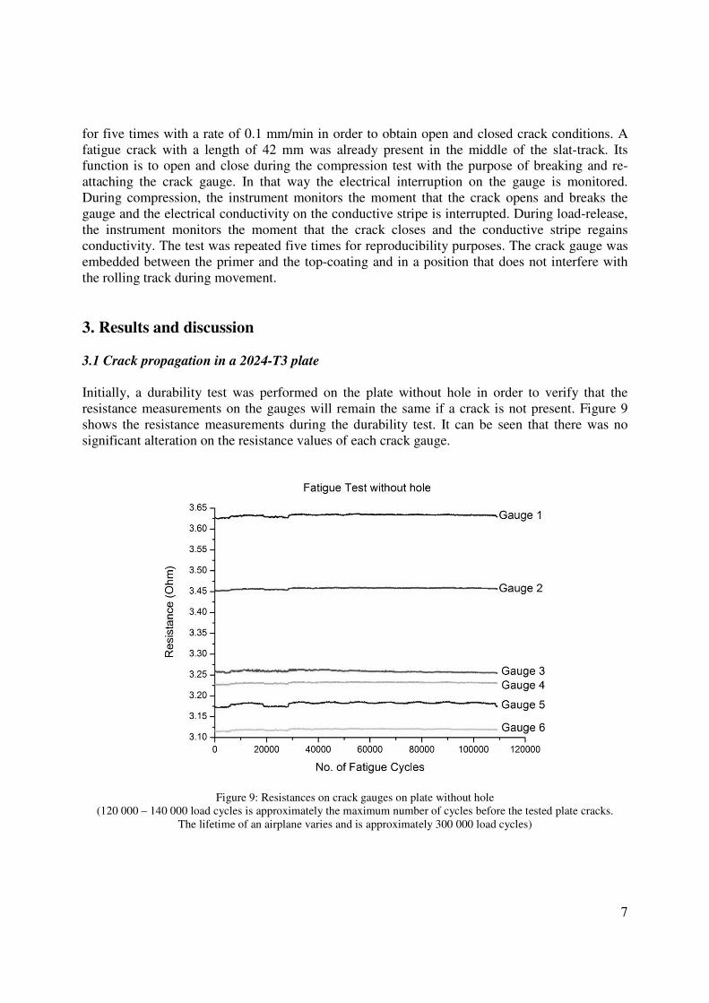
Initially, a durability test was performed on the plate without hole in order to verify that the
resistance measurements on the gauges will remain the same if a crack is not present. Figure 9
shows the resistance measurements during the durability test. It can be seen that there was no
significant alteration on the resistance values of each crack gauge.
Figure 9: Resistances on crack gauges on plate without hole
(120 000 – 140 000 load cycles is approximately the maximum number of cycles before the tested plate cracks.
The lifetime of an airplane varies and is approximately 300 000 load cycles)
Page 8
8
After the durability test, a hole of 3.5 mm diameter was drilled and a second fatigue test was
performed. The plate was loaded in fatigue and the crack propagated horizontally and passed
through all six gauges before the fatigue test was stopped at 135 000 cycles, see figure 10.
Figure 10: Six embedded gauges and direction of crack propagation
Figure 11 shows the time that the electrical conductivity of each gauge is interrupted during the
fatigue test. As the crack is growing, it breaks consecutively the gauges and they show infinite
values of resistance, thus no conductivity. As expected, the gauges 3 and 4 are the first that lose
conductivity.
Figure 11: Interruption of electrical resistance on the 6 gauges on the aluminium alloy 2024-T3 plate
Page 9
9
The crack appeared after 105 000 cycles and Figure 12 shows the crack growth at the left and the
right side of the hole as a function of the fatigue cycles. It can be seen that the crack grew up to a
length of 10 mm at each side after an additional 26 000 fatigue cycles. At this point, the crack has
passed through all six embedded gauges. This means that the crack has broken all six gauges, and
when the crack is open, all gauges have resistance values that are out of range. An out of range
resistance measurement means that the measurements are way out of the initial values and the
instrument shows an infinite value due to the interruption of conductivity.
Figure 12: Crack growth starting at 105 000 cycles (first appearance of crack)
At the end of the fatigue test, the crack had interrupted the electrical conductivity in all six
gauges. To monitor the possibility of regaining conductivity when the crack was closed another
small test was performed. The plate was subjected to a static load of 10 kN keeping the crack
open. When the crack was open, all gauges (1-6) lost conductivity showing almost infinite values
of resistance. Then, the static load was slowly decreasing to zero and the crack was closing again.
Following this procedure, it can be observed if the gauges will regain conductivity and at which
load. Table 1 shows the results.
Table 1: Conductivity on each crack gauge after cracking
Gauge
Resistance Before Test
(Ohm)
Resistance After End of Test
(Ohm)
Conductivity
regained
1 3,626 5,993 then Out of range (-> ∞ ) Yes at 6 kN
2 3,452 Out of range (-> ∞ ) No
3 3,227 Out of range (-> ∞ ) No
4 3,173 Out of range (-> ∞ ) No
5 3,115 Out of range (-> ∞ ) No
6 3,259 5,149 then Out of range (-> ∞ ) Yes at 0 kN
Page 10
10
The results showed that gauges 2, 3, 4 and 5 did not regain conductivity after the completion of
the test. However, the crack gauges 1 and 6 that were positioned far away from the hole and near
the end of the crack, initially regained conductivity for a period of time but the resistance was
increasing until it showed values out of range. The results confirm that when these gauges are
monitored, they can detect cracks propagating through the gauge causing interruption of electrical
conductivity. Nevertheless, further tests need to be performed in order to optimize the crack
gauge.
3.2 Airbus A320 slat-track
The Airbus A320 slat-track was subjected to a 3 point bending test with a load up to 2 kN and
then it was released. An artificial crack was already present on the slat-track and the main
purpose of the test was to investigate the reliability of the crack gauge when the crack was open
and closed again. When the slat-track is compressed, the crack on the slat-track opens and breaks
the gauge. In release mode, the crack closes and the gauge is reattached. Table 2 shows the
vertical extension of the slat-track with respect to the compressive load applied.
Table 2: Compressive extension and load on A320 slat-track
Load Compressive extension (mm) Compressive load (kN)
Minimum 0,09 0,014
Maximum 3,54 2,049
The slat-track was compressed five times to test the reproducibility. The instruments monitor the
exact point where the resistance becomes infinite, thus there is an interruption of the electrical
conductivity. The loss of conductivity occurs at 0.6 kN during compression. At the same time,
when the load on the slat-track is released, it can be observed that the crack gauge regains
conductivity when the crack is closing. This occurs again almost at the same compressive load at
0.6 kN.
Figure 13: Resistance measurements and load (dashed line: electrical resistance, dark line: load)
Page 11
11
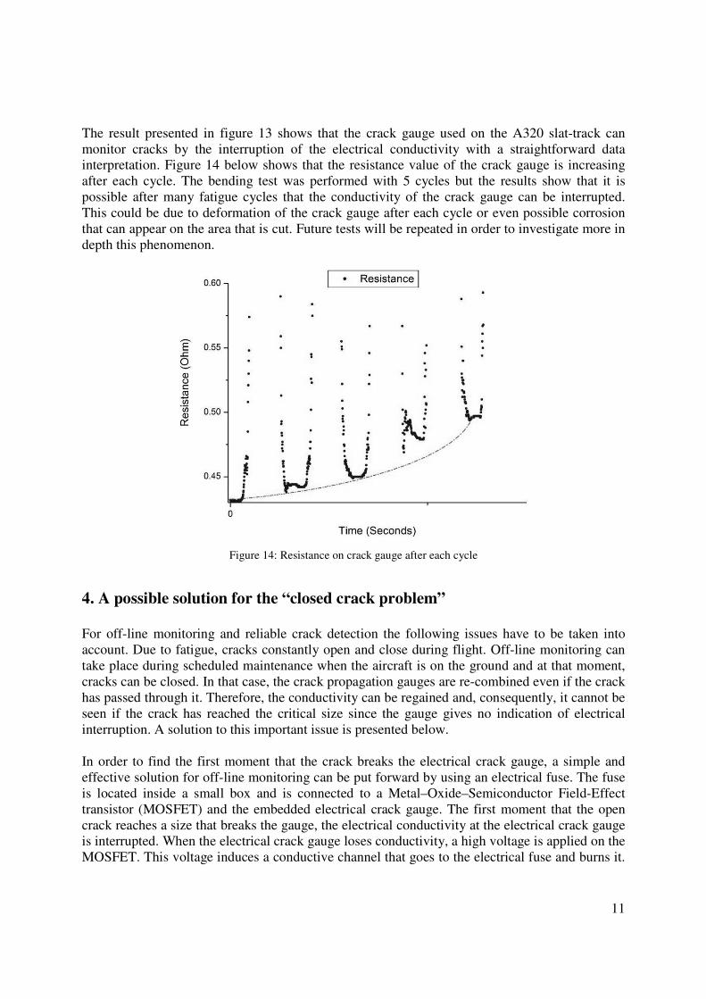
The result presented in figure 13 shows that the crack gauge used on the A320 slat-track can
monitor cracks by the interruption of the electrical conductivity with a straightforward data
interpretation. Figure 14 below shows that the resistance value of the crack gauge is increasing
after each cycle. The bending test was performed with 5 cycles but the results show that it is
possible after many fatigue cycles that the conductivity of the crack gauge can be interrupted.
This could be due to deformation of the crack gauge after each cycle or even possible corrosion
that can appear on the area that is cut. Future tests will be repeated in order to investigate more in
depth this phenomenon.
Figure 14: Resistance on crack gauge after each cycle
4. A possible solution for the “closed crack problem”
For off-line monitoring and reliable crack detection the following issues have to be taken into
account. Due to fatigue, cracks constantly open and close during flight. Off-line monitoring can
take place during scheduled maintenance when the aircraft is on the ground and at that moment,
cracks can be closed. In that case, the crack propagation gauges are re-combined even if the crack
has passed through it. Therefore, the conductivity can be regained and, consequently, it cannot be
seen if the crack has reached the critical size since the gauge gives no indication of electrical
interruption. A solution to this important issue is presented below.
In order to find the first moment that the crack breaks the electrical crack gauge, a simple and
effective solution for off-line monitoring can be put forward by using an electrical fuse. The fuse
is located inside a small box and is connected to a Metal–Oxide–Semiconductor Field-Effect
transistor (MOSFET) and the embedded electrical crack gauge. The first moment that the open
crack reaches a size that breaks the gauge, the electrical conductivity at the electrical crack gauge
is interrupted. When the electrical crack gauge loses conductivity, a high voltage is applied on the
MOSFET. This voltage induces a conductive channel that goes to the electrical fuse and burns it.
Page 12
12
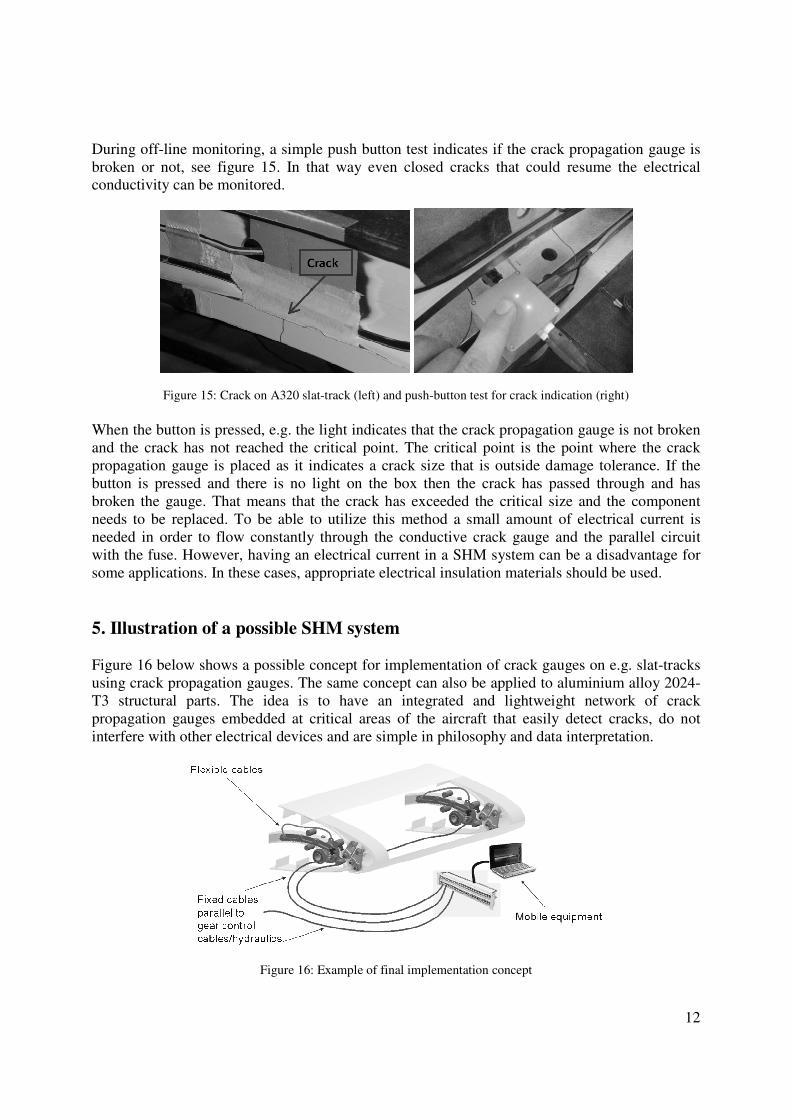
During off-line monitoring, a simple push button test indicates if the crack propagation gauge is
broken or not, see figure 15. In that way even closed cracks that could resume the electrical
conductivity can be monitored.
Figure 15: Crack on A320 slat-track (left) and push-button test for crack indication (right)
When the button is pressed, e.g. the light indicates that the crack propagation gauge is not broken
and the crack has not reached the critical point. The critical point is the point where the crack
propagation gauge is placed as it indicates a crack size that is outside damage tolerance. If the
button is pressed and there is no light on the box then the crack has passed through and has
broken the gauge. That means that the crack has exceeded the critical size and the component
needs to be replaced. To be able to utilize this method a small amount of electrical current is
needed in order to flow constantly through the conductive crack gauge and the parallel circuit
with the fuse. However, having an electrical current in a SHM system can be a disadvantage for
some applications. In these cases, appropriate electrical insulation materials should be used.
5. Illustration of a possible SHM system
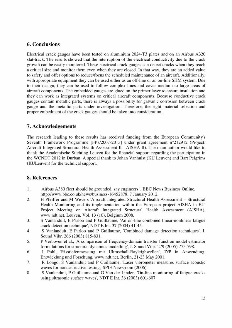
Figure 16 below shows a possible concept for implementation of crack gauges on e.g. slat-tracks
using crack propagation gauges. The same concept can also be applied to aluminium alloy 2024-
T3 structural parts. The idea is to have an integrated and lightweight network of crack
propagation gauges embedded at critical areas of the aircraft that easily detect cracks, do not
interfere with other electrical devices and are simple in philosophy and data interpretation.
Figure 16: Example of final implementation concept
Page 13
13
6. Conclusions
Electrical crack gauges have been tested on aluminium 2024-T3 plates and on an Airbus A320
slat-track. The results showed that the interruption of the electrical conductivity due to the crack
growth can be easily monitored. These electrical crack gauges can detect cracks when they reach
a critical size and monitor them even when they are closed. In that way, they are an added value
to safety and offer options to reduce/focus the scheduled maintenance of an aircraft. Additionally,
with appropriate equipment they can be used either as an off-line or an on-line SHM system. Due
to their design, they can be used to follow complex lines and cover medium to large areas of
aircraft components. The embedded gauges are glued on the primer layer to ensure insulation and
they can work as integrated systems on critical aircraft components. Because conductive crack
gauges contain metallic parts, there is always a possibility for galvanic corrosion between crack
gauge and the metallic parts under investigation. Therefore, the right material selection and
proper embedment of the crack gauges should be taken into consideration.
7. Acknowledgements
The research leading to these results has received funding from the European Community's
Seventh Framework Programme [FP7/2007-2013] under grant agreement n°212912 (Project:
Aircraft Integrated Structural Health Assessment II - AISHA II). The main author would like to
thank the Academische Stichting Leuven for the financial support regarding the participation in
the WCNDT 2012 in Durban. A special thank to Johan Vanhulst (KU Leuven) and Bart Pelgrims
(KULeuven) for the technical support.
8. References
1 . 'Airbus A380 fleet should be grounded, say engineers ', BBC News Business Online,
http://www.bbc.co.uk/news/business-16452878, 7 January 2012.
2. H Pfeiffer and M Wevers 'Aircraft Integrated Structural Health Assessment – Structural
Health Monitoring and its implementation within the European project AISHA in EU'
Project Meeting on Aircraft Integrated Structural Health Assessment (AISHA),
www.ndt.net, Leuven, Vol. 13 (10), Belgium 2008.
3. S Vanlanduit, E Parloo and P Guillaume, 'An on-line combined linear-nonlinear fatigue
crack detection technique', NDT E Int. 37 (2004) 41-45.
4. S Vanlanduit, E Parloo and P Guillaume, 'Combined damage detection techniques', J.
Sound Vibr. 266 (2003) 815-831.
5. P Verboven et al., 'A comparison of frequency-domain transfer function model estimator
formulations for structural dynamics modelling', J. Sound Vibr. 279 (2005) 775-798.
6. J Pohl, 'Risstiefenmessung mit Ultraschall-Rayleighwellen', ZfP in Anwendung,
Entwicklung und Forschung, www.ndt.net, Berlin, 21-23 May 2001.
7. R Longo, S Vanlanduit and P Guillaume, 'Laser vibrometer measures surface acoustic
waves for nondestructive testing', SPIE Newsroom (2006).
8. S Vanlanduit, P Guillaume and G Van der Linden, 'On-line monitoring of fatigue cracks
using ultrasonic surface waves', NDT E Int. 36 (2003) 601-607.
Page 14
14
9. S Vanlanduit et al., 'Damage Assessment of Structures Vi', Trans Tech Publications Ltd,
pp. 549-556, Zurich-Uetikon 2005.
10. H. Pfeiffer et al., 'Structural Health Monitoring of Slat Tracks using transient ultrasonic
waves', EU Project Meeting on Aircraft Integrated Structural Health Assessment
(AISHA), Leuven, Belgium, June 2007.
11. European Project 'Aircraft Integrated Structural Health Assessment (AISHA) II',
www.aisha2.eu, Seventh Framework Programme, European Union.
12. European project 'Cooperative Hybrid Objects Sensor Networks (CHOSeN) ',
www.chosen.eu, Seventh Framework Programme, European Union.
13. R Shevell, 'Fundamentals of flight', ISBN 0133390608, Englewood Cliffs, Ch. 18, pp
373-386, Prentice Hall 1989.
14. D Crane, 'ASAS Dictionary of Aeronautical Terms', ISBN 0940732610, Aviation
Supplies & Academics Incorporated, 1987.


![0) · 2016. 7. 8. · x\hsp[`th`]hy`klwlukpunvu svjh[pvu ;opz^psshhlj[Äuhs lhkpunz ... pj /\tpjhjpk)sluk-sv^ly luohujly t3 t3 t3 t3 t3 t3 t3 t3 t3 t3 t3 t3 t3 t3 t3 t3 t3 t3 t3 t3](https://static.documents.pub/doc/80x56/60d98d4a31005a4c8d3c5fa4/0-2016-7-8-xhspthhyklwlukpunvu-svjhpvu-opzpsshhljuhs-lhkpunz-.jpg)


