Journal of the Mechanics and Physics of Solids 50 (2002) 1079–1098 www.elsevier.com/locate/jmps Plastic ratcheting induced cracks in thin lm structures M. Huang a ; 1 , Z. Suo a ; ∗ , Q. Ma b a Mechanical and Aerospace Engineering Department, Princeton Materials Institute, Princeton University, P.O. Box CN5263, Princeton, NJ 08544-5263, USA b Intel Corporation, 2200 Mission College Blvd., Santa Clara, CA 95052, USA Received 25 May 2001; accepted 18 August 2001 Abstract In the microelectronic and photonic industries, temperature cycling has long been used as a reliability test to qualify integrated materials structures of small feature sizes. The test is time cons umi ng, and is a bott leneck for innovation. Tre mendous nee ds exis t to unde rst and vari ous fai lur e modes in the int egr ated str uct ures caused by cycl ic temp erat ure s. This paper pres ents a systematic st udy of a fail ur e mec han ism recentl y discover ed by the authors. In a thin l m structure comprising both ductile and brittle materials, the thermal expansion mismatch can cause the ductile material to plastically yield in every temperature cycle. Under certain circumstances, the plastic deformation ratchets, namely, accumulates in the same direction as the temperature cyc les . The ratchet ing defor mation in the ductile material may build up st ress in the br it tl e materials, leading to cracking. The paper introduces an analogy between ratcheting and viscous ow. An analytical model is developed, which explains the experimental observations, and allows one to desi gn the st ruct ur e to avert this failur e mod e. Des ign rules wi th incr eas ing level s of sophistication are described. Concepts presented here are generic to related phenomena in thin lm structures. ? 2002 Elsevier Science Ltd. All rights reserved. Keywords: Temperature cycling; Plasticity; Thin lms; Ratcheting; Cracking 1. Introd uction Temperature cycling is widely used in the industry to qualify integrated small struc- tur es of dis simila r mat eri als . Aft er bei ng cyc led bet wee n two temper atu res for hun- dre ds and thousa nds of times, a str uct ure is sec tioned and exami ned in mic ros copes ∗ Corresponding author. Tel.: +1-609-258-0250; fax: +1-609-258-5877. E-mail address: [email protected] (Z. Suo). 1 Current address: Lightcross Inc., 2630 Corporate Place, Monteray Park, CA 91754, USA. 0022-5096/02/$ - see front matter? 2002 Elsevier Science Ltd. All rights reserved. PII: S0022-5 096(01) 00113-2
Plastic ratcheting induced cracks in thin lmstructures
M. Huanga ;1, Z. Suoa ;∗, Q. Ma b
a
Mechanical and Aerospace Engineering Department, Princeton Materials Institute,Princeton University, P.O. Box CN5263, Princeton, NJ 08544-5263, USA bIntel Corporation, 2200 Mission College Blvd., Santa Clara, CA 95052, USA
Received 25 May 2001; accepted 18 August 2001
Abstract
In the microelectronic and photonic industries, temperature cycling has long been used as a
reliability test to qualify integrated materials structures of small feature sizes. The test is time
consuming, and is a bottleneck for innovation. Tremendous needs exist to understand various
failure modes in the integrated structures caused by cyclic temperatures. This paper presents
a systematic study of a failure mechanism recently discovered by the authors. In a thin lm
structure comprising both ductile and brittle materials, the thermal expansion mismatch can cause
the ductile material to plastically yield in every temperature cycle. Under certain circumstances,
the plastic deformation ratchets, namely, accumulates in the same direction as the temperature
cycles. The ratcheting deformation in the ductile material may build up stress in the brittle
materials, leading to cracking. The paper introduces an analogy between ratcheting and viscous
ow. An analytical model is developed, which explains the experimental observations, and allows
one to design the structure to avert this failure mode. Design rules with increasing levels of
sophistication are described. Concepts presented here are generic to related phenomena in thin
lm structures. ? 2002 Elsevier Science Ltd. All rights reserved.
Keywords: Temperature cycling; Plasticity; Thin lms; Ratcheting; Cracking
1. Introduction
Temperature cycling is widely used in the industry to qualify integrated small struc-
tures of dissimilar materials. After being cycled between two temperatures for hun-
dreds and thousands of times, a structure is sectioned and examined in microscopes
1080 M. Huang et al. / J. Mech. Phys. Solids 50 (2002) 1079 – 1098
for failure (e.g., distortion and cracking). If a failure mode is found, modications are
made in the next iteration of the structure by changing either materials, geometries,
or processing parameters. The modied structure is temperature cycled again, followed
by the microscopy examination. The iterations do not guarantee convergence, as themodications made to avert one failure mode may cause another failure mode. These
make-and-break iterations are extremely time consuming, and are a bottleneck for in-
novation. Consequently, it is imperative to understand various failure modes caused
by temperature cycling. Such understanding would greatly impact the microelectronic,
photonic and MEMS industries, where complex structures of small feature sizes are
made, and miniaturalization and novel functionality demand new structures to be qual-
ied rapidly. This paper systematically examines a failure mode recently discovered by
the authors (Huang et al., 2000).
Fig. 1a illustrates a ip-chip package. A silicon die is bonded to a packaging sub-
strate, with the interconnect structure facing the packaging substrate. Between the die
and the substrate are layers of polymers (epoxy underll and polyimide) and solder
bumps. Fig. 1b details the left corner of the die. Illustrated is a metal (aluminum or
copper) lm of the top level interconnects on a dielectric (silica), with a silicon nitride
(SiN) passivation lm covering the metal lm and silica. The SiN lm is deposited
over the interconnect structure before the die is bonded to the packaging substrate.
Since the packaging substrate has a larger thermal expansion coecient than the sili-
con die, upon cooling from the curing temperature, a shear stress 0 develops on the
silicon die, pointing toward the die center (Alpern et al., 1994; Nguyen et al., 1995;
Liu et al., 1999). Leading failure modes in the ip-chip package caused by tempera-ture cycling include die–polymer or polymer–substrate debonding (Yan and Agarwal,
1998; Gurumurthy et al., 1998), solder bump detachment (Lau et al., 1998), metal
lm crawling (Huang et al., 2001a; Alpern et al., 1994; Isagawa et al., 1980; Thomas,
1985), and SiN lm cracking (Huang et al., 2000; Michaelides and Sitaraman, 1999;
Edwards et al., 1987; Alpern et al., 1994; Nguyen et al., 1995; Pendse, 1991, Gee et
al., 1995). This paper focuses on SiN lm cracking.
Fig. 1c is a schematic plan view of the die surface near a corner. Plan view mi-
crographs of several interconnect test structures are shown in Fig. 2. The exact testing
conditions are unavailable to us, but the observations are generic. After about 1000
cycles between −55◦
C and +125◦
C, the packaging substrate and the polymers areremoved to expose the die surface. Cracks are observed in the SiN lm over the metal
lm. The main experimental observations are as follows.
• Cracking occurs in the SiN lm at the die corners.
• Cracking occurs after temperature cycles, and becomes more extensive as the number
of cycles increases.
• Cracking occurs in the SiN lm over the metal lms, but not in the SiN lm over
silica.
• Cracking is more likely when the metal lms are wide and the SiN lm is thin.
Passivation lm cracking has been observed for many years (Michaelides and Sitara-man, 1999; Edwards et al., 1987; Alpern et al., 1994; Nguyen et al., 1995; Pendse,
1991, Gee et al., 1995). Two questions have been intriguing. Why should cracks occur
1082 M. Huang et al. / J. Mech. Phys. Solids 50 (2002) 1079 – 1098
Fig. 2. Plan view micrographs of several interconnect test structures. The lighter region corresponds to
aluminum lm, and the darker region corresponds to silica dielectric. The entire surface is covered by a thin
SiN lm. Cracks are observed in SiN over the aluminum lm after many temperature cycles.
much lower than that of the packaging substrate. The dierential thermal expansion
induces the shear stress, 0, at the die corners upon cooling from the curing temperature
(Fig. 1b). When the temperature cycles in a range below the curing temperature, the
shear stress 0 always points toward the center of the die. The shear stress 0 is partly
sustained by a membrane stress in the passivation lm, and partly transmitted to themetal lm underneath as a shear stress in the metal, m. The metal lm also has a
large thermal expansion mismatch with silicon and silica beneath, so that the metal lm
plastically yields in every temperature cycle. When the metal yields, the small shear
stress in the metal, m, will cause the metal to deform in shear plastically. The in-plane
plastic strain in the metal lm is constrained by the elastic substrate. Consequently,
the amount of plastic shear strain increment per cycle in the metal is small, as will
become evident later when we look at the model closely. The increment of the shear
strain is in the same direction as the shear stress on the passivation lm 0, which is
always in the same direction during the temperature cycling. Incrementally, the shear
stress in the metal lm m relaxes, and the membrane stress in the overlaying siliconnitride lm builds up. It is this evolving stress state that cracks the SiN lm after some
M. Huang et al. / J. Mech. Phys. Solids 50 (2002) 1079–1098 1083
The deformation in the same direction caused by a cyclic load (temperature change
in this case) is known as ratcheting deformation (Bree, 1967; Suresh, 1998; Jansson
and Leckie, 1992). Several examples of ratcheting in thin lm structures have been
discovered recently (Begley and Evans, 2001; He et al., 2000; Huang et al., 2000,2001a; Karlsson and Evans, 2001). As it turns out, these examples can all be understood
in terms of a ratcheting-creep analogy to be introduced in this paper.
Huang et al. (2000) analyzed a plane strain model of passivation lm cracking.
The nite element method was used to evolve the stress eld incrementally as the
temperature changes. After many temperature cycles, the structure reached a steady
state, in which the stress eld in the passivation lm remained unchanged and the
metal lm underwent cyclic plastic deformation upon further temperature cycling. In
this paper, we will address two important issues that we could not address in the
previous paper. First, in the previous paper, to limit the amount of computation, we
assigned a low metal yield strength, so that the number of cycles needed to approach the
steady state is limited below about 100. Second, to avert cracking, an industrial practice
is to change the shape and size of the metal lm. Consequently, to aid the industrial
practice, we would like to do calculations over thousands of temperature cycles, for
three-dimensional structures, and for many geometrical designs. Direct nite element
calculation would require too much time to be practical.
This paper will develop analytical methods to circumvent these diculties. The plan
of the paper is as follows. Section 2 reviews the model of crawling of a blanket metal
lm, and introduces the concept of ratcheting-viscosity. In Section 3, a ratcheting-creep
analogy is developed to analyze the evolving stress eld in the passivation lm as themetal lm ratchets. Section 4 extends the ideas into a two-dimensional model to evolve
stress eld in a passivation lm over a metal lm of an arbitrary shape. As will be
shown later, the normal stresses in the passivation lm build up during temperature
cycling, and reach the maximum value at the steady state. The steady state corresponds
to a plane stress eld, which can be rapidly determined by using a commercial nite
element package.
2. Crawling of a blanket lm on a semi-innite substrate
Metal lms near a die corner are sometimes observed to crawl toward the die cen-
ter during temperature cycling (Alpern et al., 1994; Isagawa et al., 1980; Thomas,
1985). Such crawling breaks passivation lms, and may even break thin metal lines
themselves by excessive distortion (J.B. Han, private communication). Huang et al.
(2001a) have developed an idealized model to study this phenomenon. This section
casts the key results in a form useful for the present work. Fig. 3a illustrates a blanket
metal lm bonded on a semi-innite elastic substrate. Throughout the paper, the metal
is taken to be elastic and perfectly plastic, with an yield strength independent of the
temperature within the range of the temperature cycling. Cycle the structure between
temperatures T L and T H. At any given time, the whole structure is taken to have auniform temperature. The eect of non-uniform temperature will not be studied in this
paper. A shear stress, m, acts on the surface of the metal lm. For the time being, this
1084 M. Huang et al. / J. Mech. Phys. Solids 50 (2002) 1079 – 1098
Fig. 3. (a) A magnied view of the left corner of the silicon die, showing the shear stress on the metal
lm. (b) The stress state in the lm. (c) The yield surface.
shear stress is taken to be spatially uniform, and remains constant as the temperature
cycles.
Under these assumptions, the stress eld in the structure is very simple. The semi-
innite substrate is subject to the same shear stress m, but no other stress components.Let the coordinates in the plane of the lm be x1 and x2, the coordinate normal to the
plane be x3, and the coordinate x1 coincide with the direction of the shear stress m.
1086 M. Huang et al. / J. Mech. Phys. Solids 50 (2002) 1079 – 1098
The yield condition is an ellipse on the (m ; m) plane (Fig. 3c). The metal lm is
elastic when the stress state is inside the ellipse, and yields when the stress state is on
the ellipse. The stress state outside the ellipse cannot be attained by the metal. When
the lm yields, for a given m, the biaxial stress can only be at one of the two levels:
m = ±
Y 2 − 32m : (8)
These two stress states, tensile and compressive, are indicated in Fig. 3c.
The J 2 ow theory dictates that the plastic strain increment tensor is in the same
direction as the deviatoric stress tensor, namely, dij = s pij d, where d is a scalar.
Consequently, from Eq. (6) we obtain that
d p
m= 3 =
d p
2m
; (9)
where p = 2 p13 is the plastic shear strain in the lm. Eq. (9) is the key to the un-
derstanding of metal lm crawling. Its geometric interpretation is well known: the
increment of the plastic strain tensor points in the direction normal to the yield surface
(Fig. 3c). During plastic deformation, d p has the same sign as the biaxial stress m,
and d p has the same sign as the shear stress m. When the temperature rises to yield
the lm in compression (m ¡ 0), the plastic in-plane strain decreases, d p ¡ 0. When
the temperature drops to yield the lm in tension (m ¿ 0), the plastic in-plane strain
increases, d p ¿ 0. Since the lm is bonded to the substrate, for a given temperature
increment, d p is always nite. Consequently, in each cycle, p increases by a niteamount in the direction of m, both when the lm is in tension and in compression.
It is this feature that causes the lm to crawl in the same direction as the temperature
cycles.
During metal lm yielding, dm =0 and de = 0. For a given temperature increment
dT , Eq. (2) gives the increment of the plastic in-plane strain
d p =− (m − s) dT: (10)
The plastic in-plane strain increment in the lm equals the thermal mist strain
increment. Substituting Eq. (10) into the J 2 ow rule, Eq. (9), gives the increment of the plastic shear strain
d p =− 6m
m
(m − s) dT: (11)
When the lm plastically deforms in tension, m = +
Y 2 − 32m and dT ¡ 0. When
the lm plastically deforms in compression, m =−
Y 2 − 32m and dT ¿ 0. In either
case, the plastic shear strain increment is in the same direction of m, namely, d p ¿ 0,
giving rise to crawling. Fig. 4a shows the prescribed temperature change with time.
Fig. 4b shows the plastic shear strain as a function of the temperature. The plasticshear strain remains constant when the metal lm is elastic, and increases when the
M. Huang et al. / J. Mech. Phys. Solids 50 (2002) 1079–1098 1087
Fig. 4. (a) The prescribed temperature changes with time. (b) The plastic shear strain as a function of the
temperature.
The ratcheting strain rate (i.e. the plastic shear strain increment per temperature
cycle) can be obtained by using Eq. (11) and following through a cycle (CDEFC’
in Fig. 4):
p = 12(1− m)m
E m
E m(m − s)(T H − T L)
(1− m)
Y 2 − 32m
− 2
: (12)
Fig. 5 plots the ratcheting strain rate, p, as a function of the shear stress, m. We
make an analogy between the strain per temperature cycle (i.e. the ratcheting rate) and
the strain per unit time (i.e. the strain rate). Fig. 5 is thus analogous to the relation
between strain rate and stress in viscous ow. In general, we write the ratcheting rate
law as 9 p= 9 N = f(m). The shear stress should be bounded as m=Y ¡ 1= √
3; otherwise
the lm has unlimited plastic shear strain even without the temperature change. As
m=Y
→ 1= √
3, the ratcheting rate becomes large for any given temperature ranges.
Depending on the temperature range, we distinguish several behaviors as follows.When E m(m − s)(T H − T L)= (1 − m)Y ¿ 2, the temperature change by itself can
cause the metal lm to deform plastically in every cycle. When the shear stress is zero,
M. Huang et al. / J. Mech. Phys. Solids 50 (2002) 1079–1098 1089
When E m(m − s)(T H − T L)= (1 − m)Y = 2, for small shear stress, Eq. (12) gives
rise to a power law behavior, 9 p= 9 N ∼ 3m.
3. Ratcheting-creep analogy or cycle-time analogy
This section develops a one-dimensional model of ratcheting of the thin lm struc-
tures. As shown in Fig. 6, a metal lm is in a thick elastic substrate, and the passivation
thin lm is on the metal lm and the substrate. A shear stress, 0, due to the pack-
aging substrate, is applied on the passivation lm. The shear stress 0 is limited by
the yield strength of the underll, on the order 10–100 MPa, and is assumed to be
constant during analysis. A variable 0 can be incorporated in our model, but will not
be incorporated in this paper. The metal lm is of thickness hm and length L. The passivation lm is of thickness h p. Cycle the structure between T H and T L. The shear
stress in the metal lm is m, and the normal stress in the passivation lm is . Now
both m and are allowed to vary with the number of cycles, N , and the position, x.
We expect m to vary slowly with N and x, so that we will use the ratcheting rate
law obtained in the previous section.
First look at the elastic passivation lm. As shown in the inset in Fig. 6, the passi-
vation lm is subjected to a membrane stress ( N; x), a constant shear stress 0 on
Fig. 6. Illustration of one-dimensional structure of passivation lm on the metal lm and substrate. The
insets show the dierent element and the stress state of the passivation lm, and the stress and ow in the
M. Huang et al. / J. Mech. Phys. Solids 50 (2002) 1079–1098 1091
In the steady state, 0 is fully sustained by the membrane stress in the passivation
lm, giving rise to a linear membrane stress distribution, and a parabolic displacement
distribution.
Analogous to any diusion problem, the characteristic number of cycles to reach thesteady state can be estimated by N C = L2=D, or
N C =
L2
hmh p
E m
12 E p(1− m)
E m(m − f)(T H − T L)
(1− m)Y − 2
−1
: (22)
The number N C can be large mainly because the ratio L2= (hmh p) is large. If one
replaces the metal lm with a plastically deformable polymer, the ratio of elastic mod-
ulus of the polymer and the passivation is small, which would signicantly reduce N C.
Note that N C is independent of 0.
In order to solve Eq. (18) for evolving stress as the temperature cycles, we need
to set the initial condition. Before the temperature cycles, the applied shear stress is
balanced by the shear stress in the metal, 0 ≈ m, so that the membrane stress in the
passivation lm is nearly zero, ≈ 0, and the initial condition is
u =0 at N = 0 for all x: (23)
Using boundary conditions (20) and initial condition (23), we can solve diusion
equation (18). The membrane stress distribution in the passivation lm is
= 0 L
h p
k =0;1;:::
4(−1)k
(2k + 1)22 exp
− (2k + 1)22 N
N C
sin
2k + 1
L x
− x
L
(24)
and the shear stress distribution in the metal lm is
m = 0
k =0;1;:::
4(−1)k
(2k + 1) exp
− (2k + 1)22 N
N C
cos
2k + 1
L x
: (25)
As the number of thermal cycles increases, the shear stress decreases and the magni-
tude of the membrane stress increases. When the number of thermal cycles is innite,the shear stress approaches zero and the normal stress approaches the steady state.
We have made several approximations in this model. The ratcheting strain–stress law
(17) is obtained by an analysis of a blanket lm under uniform stress. We now allow
m to be a function of N and x. Furthermore, the plane strain eld is approximated by
a shear lag model.
To validate the model, a comparison with the nite element calculation is made. In
the nite element calculation, the metal was taken to be elastic and perfectly plastic,
with Young’s modulus 130 GPa, and yield strength 120 MPa. The substrate and the
passivation lm were taken to be elastic, with Young’s modulus 162 GPa. We took
0 = 10 MPa, and the temperature cycle range 165◦
C. The calculation was done byusing the commercial nite element software, ABAQUS, adopting four-node quadri-
lateral plane strain element. To ensure that the deformation was in the plane strain
1092 M. Huang et al. / J. Mech. Phys. Solids 50 (2002) 1079 – 1098
Fig. 7. The normalized shear stress distribution in the metal lm for several numbers of thermal cycles.
Fig. 8. The normalized membrane stress distribution in the passivation lm for several numbers of thermal
cycles.
state as the temperature changes, we set the thermal expansion coecient of the sub-
strate and the passivation lm to be zero, and the thermal expansion coecient of the
metal lm to be 13 × 10−6 K −1. The structure is shown in Fig. 2b. The metal lm is
100 m wide and 2 m thick. The periodic boundary condition is used. Fig. 7 shows
the normalized shear stress distribution in the metal lm. Fig. 8 shows the normalized
membrane stress distribution in the passivation lm. Aside from the edges, our modeland the FEM calculation predict similar stress distribution and the similar number of
cycles to reach the steady state. As expected, the agreement becomes poor near the
M. Huang et al. / J. Mech. Phys. Solids 50 (2002) 1079–1098 1093
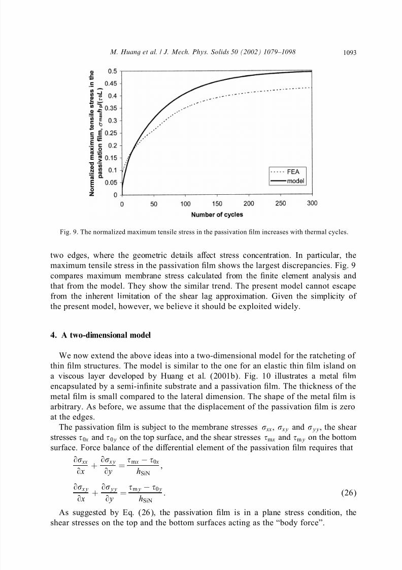
Fig. 9. The normalized maximum tensile stress in the passivation lm increases with thermal cycles.
two edges, where the geometric details aect stress concentration. In particular, the
maximum tensile stress in the passivation lm shows the largest discrepancies. Fig. 9
compares maximum membrane stress calculated from the nite element analysis and
that from the model. They show the similar trend. The present model cannot escape
from the inherent limitation of the shear lag approximation. Given the simplicity of the present model, however, we believe it should be exploited widely.
4. A two-dimensional model
We now extend the above ideas into a two-dimensional model for the ratcheting of
thin lm structures. The model is similar to the one for an elastic thin lm island on
a viscous layer developed by Huang et al. (2001b). Fig. 10 illustrates a metal lm
encapsulated by a semi-innite substrate and a passivation lm. The thickness of the
metal lm is small compared to the lateral dimension. The shape of the metal lm isarbitrary. As before, we assume that the displacement of the passivation lm is zero
at the edges.
The passivation lm is subject to the membrane stresses xx, xy and yy, the shear
stresses 0 x and 0y on the top surface, and the shear stresses m x and my on the bottom
surface. Force balance of the dierential element of the passivation lm requires that
9 xx
9 x +
9 xy
9y =
m x − 0 x
hSiN
;
9 xy
9 x
+ 9yy
9y
= my − 0y
hSiN
: (26)
As suggested by Eq. (26), the passivation lm is in a plane stress condition, the
shear stresses on the top and the bottom surfaces acting as the “body force”.
1094 M. Huang et al. / J. Mech. Phys. Solids 50 (2002) 1079 – 1098
Fig. 10. Illustration of two-dimensional structure of passivation lm on the metal lm and substrate. The
insets show the dierent element and the stress state of the passivation lm, and the stress and ow in the
metal lm.
Let u and v be the displacement in x- and y-direction, respectively. The strain–
displacement relation is
xx = 9u
9 x; yy =
9v
9y; xy =
1
2
9u
9y +
9v
9 x
: (27)
Assuming that the passivation lm is isotropic and elastic, the stress–strain relation is
xx = xx
E p− p
yy
E p; yy =
yy
E p− p
xx
E p; xy =
E p
1 + p
xy : (28)
The shear stresses on the top surface of the passivation lm, 0 x and 0y, come
from the packaging substrate, and are taken to be constant. The shear stresses at the
bottom of the passivation lm, m x and my, come from the metal lm, and changeas the temperature cycles. Under the shear stress m x and my, the metal lm ratchets
according to
m x =
hm
9u
9 N ; my =
hm
9v
9 N ; (29)
where the ratcheting-viscosity is dened by Eq. (14).
Substitution of Eqs. (27)–(29) into Eq. (26) leads to
1096 M. Huang et al. / J. Mech. Phys. Solids 50 (2002) 1079 – 1098
92v
9y2 +
1− p
2
92v
9 x2 +
1 + p
2
92u
9 x9y =− (1 − 2
p)0y
E ph p
: (31)
By setting the boundary conditions u = v = 0 at all edges, Eqs. (31) can be solved byusing the nite element method. This is a linear elastic plane stress problem. We have
used the commercial nite element software, ABAQUS, adopting four-node quadrilat-
eral plane stress element.
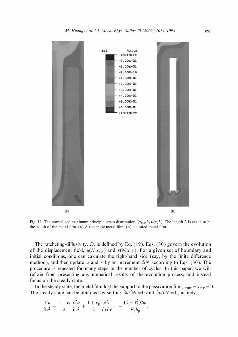
Fig. 11a shows the normalized maximum principal stress distribution at the steady
state by applying the uniform shear stress 0 in the direction of −45◦
from the x-axis.
The edges of the lm are clamped. The size of the lm is not important as the mem-
brane stresses in the passivation lm scale with 0 L=h p, where L is the width of the
metal lm. The maximum principal tensile stress is very high near the left edge and the
left upper corner, where cracking always happens. One way to reduce the membrane
stress is to use a slotted shape. Fig. 11b shows a slotted structure, where the membranestress in the passivation lm is greatly reduced.
The characteristic number of cycles to research the steady state is the same as the
one-dimensional model, Eq. (22).
5. Concluding remarks
This paper develops an analytical model to study the stress evolution in the passiva-
tion lm caused by temperature cycling. The model is based on the analogy betweenratcheting and viscous ow. Several approximations are made in this model. By com-
paring with the nite element calculation, we conrm that the model captures the main
features of the problem. The metal lm is taken to be a non-hardening material in
this model. This corresponds to a safe engineering design, as the hardening metal lm
can reduce the ratcheting eects (Huang et al., 2001a). The model can also be easily
extended to consider the non-linearity of the ratcheting-viscosity by using the nite
dierence method. The stress concentration at the edges needs to be better treated, as
the maximum tensile stress in the passivation lm is at the corner. Fracture conditions
also need to be considered more carefully (e.g., Liu et al., 2000). Several useful rules
for design are evident. First, one should aim to avoid metal lm ratcheting altogether.Under cyclic temperature, the metal lm cycles elastically if
E m(m − s)(T H − T L)
(1 − m)
Y 2 − 32
0
¡ 2: (32)
Second, if one cannot avoid ratcheting, one may aim to design the metal lm ge-
ometry such that the passivation lm can sustain the steady state, in which the stress
distribution in the passivation lm can be calculated by solving a linear elastic plane
stress problem. Third, if the characteristic number N C is much larger than the number
of cycles required by the qualication test, one may design according to the transientstress state, solving the stress eld as a function of the number of cycles. The present
model allows one to evaluate these options in design.