31
Composite Aircraft Crashworthiness - Certification by Analysis Gerardo Olivares Ph.D., NIAR-WSU JAMS 2019 Technical Review May 22nd 2019

JAMS 2017 Technical Review March 21, 2017
Composite Aircraft Crashworthiness -Certification by AnalysisGerardo Olivares Ph.D., NIAR-WSU
JAMS 2019 Technical ReviewMay 22nd 2019

• Motivation and Key Issues – The introduction of composite airframes warrants an assessment to evaluate that their
crashworthiness dynamic structural response provides an equivalent or improved level of safety compared to conventional metallic structures. This assessment includes the evaluation of the survivable volume, retention of items of mass, deceleration loads experienced by the occupants, and occupant emergency egress paths.
• Objective– In order to design, evaluate and optimize the crashworthiness behavior of composite
structures it is necessary to develop an evaluation methodology (experimental and numerical) and predictable computational tools.
• Approach– The advances in computational tools combined with the building block approach allows
for a cost-effective approach to study in depth the crashworthiness behavior of aerospace structures.
2
Crashworthiness - Certification by Analysis
Crashworthiness - Certification by Analysis• Principal Investigators & Researchers
– PI: G. Olivares Ph.D.– Researchers NIAR-WSU: S. Keshavanarayana Ph.D. , Chandresh
Zinzuwadia, Luis Gomez, Nilesh Dhole, Hoa Ly, Armando Barriga, Akhil Bhasin, Aswini Kona
– 8 Students [Graduate and Undergraduate ]• FAA Technical Monitor
– Allan Abramowitz• Other FAA Personnel Involved
– Joseph Pelletiere Ph.D.• Industry\Government Participation
– ARAC Transport Airplane Crashworthiness and Ditching Working Group [ FAA, EASA, Transport Canada, NASA, Aircraft OEMs (Boeing, Embraer, Bombardier, Cessna, Mitsubishi, Gulfstream, Airbus), DLR]
– KART – Spirit, Textron Aviation, Bombardier/Learjet– Gerard Elstak and Gerard Schakelaar – Dutch Politie – Hiromitsu Miyaki , Japan Aerospace Exploration Agency, JAXA
3
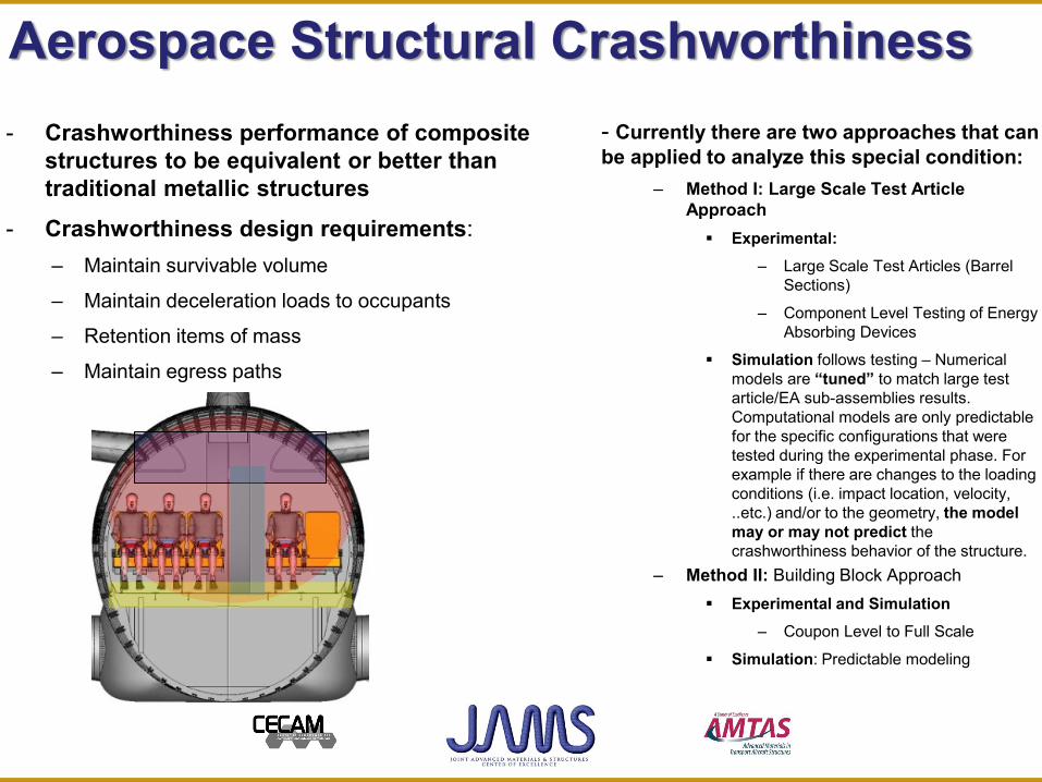
Aerospace Structural Crashworthiness- Crashworthiness performance of composite
structures to be equivalent or better than traditional metallic structures
- Crashworthiness design requirements:– Maintain survivable volume
– Maintain deceleration loads to occupants
– Retention items of mass
– Maintain egress paths
- Currently there are two approaches that can be applied to analyze this special condition:
– Method I: Large Scale Test Article Approach Experimental:
– Large Scale Test Articles (Barrel Sections)
– Component Level Testing of Energy Absorbing Devices
Simulation follows testing – Numerical models are “tuned” to match large test article/EA sub-assemblies results. Computational models are only predictable for the specific configurations that were tested during the experimental phase. For example if there are changes to the loading conditions (i.e. impact location, velocity, ..etc.) and/or to the geometry, the model may or may not predict the crashworthiness behavior of the structure.
– Method II: Building Block Approach Experimental and Simulation
– Coupon Level to Full Scale
Simulation: Predictable modeling

Crashworthiness CBA R&D Phases• Phase 0: Define Occupant Injury Limits |
FAR *.562 | • Phase I: Develop and validate occupant
ATD numerical models | SAE ARP 5765 |• Phase II: Define Modeling and
Certification by Analysis Processes of Aerospace Seat Structures and Installations |AC 20-146|SAE ARP 5765 | Aircraft OEMS and Seat Suppliers Modeling and CBA Standards |
• Phase III: Define Crashworthiness Building Block Approach for Aircraft Structures |CMH-17| ARAC Transport Airplane Crashworthiness and Ditching Working Group| Aircraft OEMS Methods|
• Phase IV: Define Structural CBA Methodology |CMH-17| ARAC Transport Airplane Crashworthiness and Ditching Working Group|
5

CBA: Composite Structures Crashworthiness
TRADITIONAL APPROACH – EXPERIMENTAL –
AIRFRAME CRASHWORTHINESS CBA
TEST DATA TO CREATE
NUMERICAL MODELS
NON PREDICTABLE MODELING
BASED ON TESTINGDEFINE CRASHWORTHINESS
REQUIREMENTS - FAR 23, 25, and 27.
AIRFRAME ENERGY DISSIPATION
REQUIREMENTS per FAR 23, 25 and
AIRCRAFT WEIGHTS (MTOW)
LOADING RATES
MATERIAL MODELING
CURRENT MATERIAL MODELING METHODS
CURRENT TEST METHODS EVALUATION – COUPON LEVEL –MODELING STUDY
FUSELAGE
LOADING RATES VARIOUS
STRUCTURAL COMPONENTS
STRAIN RATES
BASELINE FUSELAGE MODEL TEST
METHODS LIMITATIONS
FAILURE MODES
STRAIN RATE EFFECTS
TEST VARIABILITY
PREDICTABLE MODELING (VIRTUAL TESTING)
MODEL PARAMETERS
MATERIAL MODELS LIMITATIONS
IDENTIFY :
DEFINE ASTM STANDARD
DEFINE NUMERICAL MATERIAL MODELS FOR COMPOSITES/
METALLIC COMPONENTS
VALIDATE WITHTEST DATA
– COUPON LEVEL
STRAIN RATE & LOADING RATE
OBTAIN MECHANICAL PROPERTIES
VARIABILITY STUDY
NO
YES
6

CBA Composite Structures Crashworthiness
7

NIAR Drop Tests
• NIAR Crash Dynamics Laboratory
• Support ARAC for business jet size aircraft configurations
• Fuselage Section Drop Tests– Support the development of
airframe level crash requirements for business jet airplanes
– Two tests were conducted: Composites (Hawker 4000) Metallic (Cessna Citation 650)
– Impact velocity 30 ft/s– Instrumented Reaction Floor – Hardware
Digital Image Correlation Strain-gages Load Cells High Speed Videos
≈14ft
Release Mechanis
mStraps
Main Structure
Reaction Floor
Doubler Doubler
Fuselage
88

Metallic Airframe Test Article
9
General Characteristics
Seating2+7/9
External Length55 ft 6 in
External tail Height16 ft 10 in
Wing Span53 ft 6 in
Empty Weight11670 lb (5293 kg)
Gross Weight22000 lb (9979 kg)
Performance
Power
2 × Garrett TFE731-3B-100S Turbofans
3,650 lbf (16.2 kN) thrust each
Cruise Speed 554 mph (875 kmph)
Range 2345 mi (3774 km)
Service Ceiling 51000 ft

Metallic Test Section – Specifications
10
• Complete Fuselage Available• Tentative Test Article Dimensions
– Length: ≈9 ft– Diameter: ≈6 ft
• Tentative Test Article Configuration:– One Exit Door Opening (Right Side)– Seven Window Openings:
3 Right Side 4 Left Side
• Floor Structure with Seat tracks• Seat Track Width: 15” (wall mounted) • No wing box structure• No upper panels/PSUs• This article could not be used to support the ARAC program since during the
accelerometer instrumentation process we found subfloor modifications to the structure
• The fuselage section was dropped to evaluate the Release and DIC system• If funding is available an additional test is planned with a Bombardier Metallic
Fuselage:– NIAR purchased the fuselage and seats– Testing Q4 2019 or Q1 2020 depending on funding and test facility availability
10

Composite Airframe Test Article
11
General Characteristics
Seating 2+8/12
External Length 69 ft 6 in
External tail Height 19 ft 9 in
Wing Span 61ft 9 in
Empty Weight 23500 lb (10659 kg)
Gross Weight 26000 lb (11793 kg)
Performance
Power2 × Pratt & Whitney Canada
PW308A turbofan6,900 lbf/ ISA + 22 °C () each
Cruise Speed Mach 0.84
Range 6075 km
Service Ceiling 45000 ft
InteriorCabin Height 6ft
Cabin Length 25 ft
Cabin Width 6 ft 6 in
Cabin Volume 762 ft3

Composite Test Section– Aircraft Location
1212

Composite Airframe Drop Test – H4000• Dimensions:
– Length: ≈8 ft 2in– Diameter: ≈7 ft
• One Exit Door Opening (Right Side)
• Seven Window Openings: – 3 Right Side– 4 Left Side
• Floor Structure with Seat tracks• Seat Track Width: 8’ ¾” • No wing box structure• No upper panels/PSUs• Total Weight: 1553 lbs.• 4 Occupants:
– 2 Seats: HII and FAA HII– 2 Seats: Ballast Weights
representative of seats and occupants
13
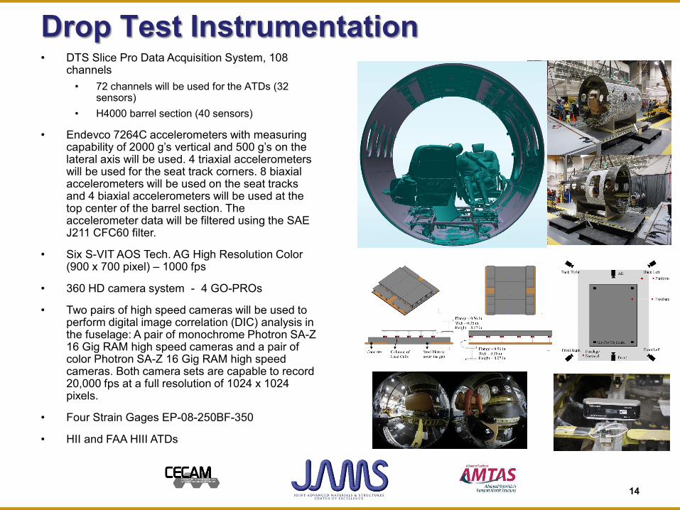
Drop Test Instrumentation
14
• DTS Slice Pro Data Acquisition System, 108 channels
• 72 channels will be used for the ATDs (32 sensors)
• H4000 barrel section (40 sensors)
• Endevco 7264C accelerometers with measuring capability of 2000 g’s vertical and 500 g’s on the lateral axis will be used. 4 triaxial accelerometers will be used for the seat track corners. 8 biaxial accelerometers will be used on the seat tracks and 4 biaxial accelerometers will be used at the top center of the barrel section. The accelerometer data will be filtered using the SAE J211 CFC60 filter.
• Six S-VIT AOS Tech. AG High Resolution Color (900 x 700 pixel) – 1000 fps
• 360 HD camera system - 4 GO-PROs
• Two pairs of high speed cameras will be used to perform digital image correlation (DIC) analysis in the fuselage: A pair of monochrome Photron SA-Z 16 Gig RAM high speed cameras and a pair of color Photron SA-Z 16 Gig RAM high speed cameras. Both camera sets are capable to record 20,000 fps at a full resolution of 1024 x 1024 pixels.
• Four Strain Gages EP-08-250BF-350
• HII and FAA HIII ATDs

HSV RWD Side and Center ViewNIAR Drop Test – Hawker 4000
15

Evaluation CriteriaNIAR Drop Test – Hawker 4000• Maintain Survivable Volume
– Overall Survivable Space Dimensional Check (Peak during Dynamic Event and Post Test Deformations)
– Avoid Occupant to Interior Structure Contacts during impact
• Maintain Deceleration Loads to Occupants– Injury Criteria Limits per 14 CFR 25.562) :
1500 lbf, HIC 1000, Shoulder Strap Loads….
• Retention Items of Mass – No items of mass such as overhead bins– Occupants and Seat Structures supported
throughout the crash event (14 CFR 25.562)• Maintain Egress Paths
– Maintain Aisle Distance (Min 12-15 inches per 14 CFR 25.815 and 25.807(d)(4))
– Evaluate Plastic deformations of the supporting structure near the exit door
– Floor Warping– Floor Beam Failures – Reduced Strength to
support passenger weight
16

Lumbar Load – HII vs. FAA HIIINIAR Drop Test – Hawker 4000
Lumbar Loads: 2500 lbs for both the HII and FAA HIII
17

Structural Failures Fuselage Structure
1818

NDT Test Results – Post-Impact Inspection
Equipment: Olympus BondMaster 600

CBA Modeling Methodology• Internal NIAR-KART R&D Full Scale Modeling• Phase I: Composite Best Modeling Practices: – 3
months– H4000 Fuselage Drop Test: Conduct
Damage Evaluation Inspection Techniques: NDE: [ Eddy current (EC) method,
Ultrasonic (US) method, Radioscopy (X), and/or Thermography ]
CTSCAN Damage Areas H4000 Fuselage Drop Test to identify failure modes.
• Phase II: Coupon and Component Level Testing program to improve predictions of composite structure failure mechanisms – 6 months
• Phase III: Update Global H4000 FEA Model and Validate with Drop Test Data – 3 months
• Phase IV: Vertical Impact Velocity SurvibabilityStudy
2020
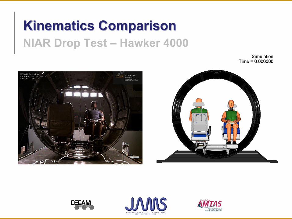
Kinematics ComparisonNIAR Drop Test – Hawker 4000
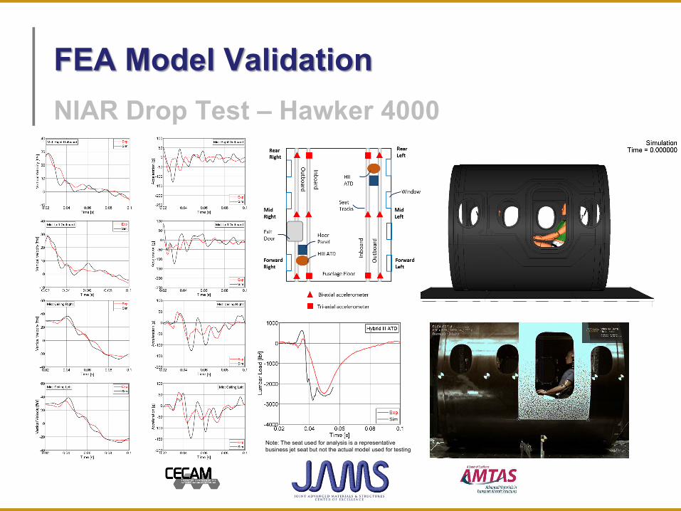
FEA Model ValidationNIAR Drop Test – Hawker 4000
Note: The seat used for analysis is a representative business jet seat but not the actual model used for testing
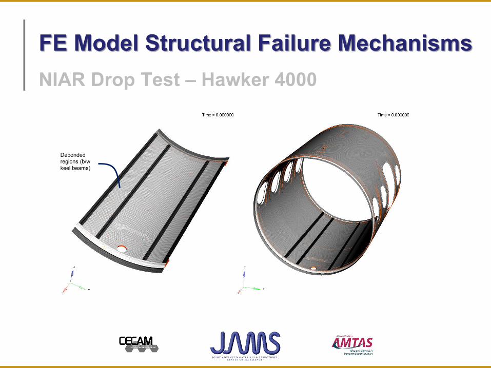
FE Model Structural Failure Mechanisms
Debondedregions (b/w keel beams)
NIAR Drop Test – Hawker 4000

Parametric Study: Velocity ProfilesHawker 4000 Drop Test Analysis
Velocity Parametric Study
Case ID DescriptionCase – 1 10 ft/s
Case – 2 15 ft/s
Case – 3 20 ft/s
Case – 4 25 ft/s
Baseline 30 ft/s

0
500
1000
1500
2000
2500
3000
3500
4000
10 15 20 25 30Lu
mba
r Loa
d [lb
f]Impact Velocity (ft/s)
Proprietary - No part of this document may be reproduced or transmitted in any form or by any means without prior written permission of NIAR
Lumbar Load Response – Hybrid III ATDParametric Study: Velocity Configurations
HIII FAA 50th ATD

Non-Integrated vs. Integrated SafetyNIAR Drop Test – Hawker 4000
27
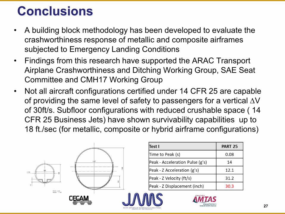
Conclusions• A building block methodology has been developed to evaluate the
crashworthiness response of metallic and composite airframes subjected to Emergency Landing Conditions
• Findings from this research have supported the ARAC Transport Airplane Crashworthiness and Ditching Working Group, SAE Seat Committee and CMH17 Working Group
• Not all aircraft configurations certified under 14 CFR 25 are capable of providing the same level of safety to passengers for a vertical ∆V of 30ft/s. Subfloor configurations with reduced crushable space ( 14 CFR 25 Business Jets) have shown survivability capabilities up to 18 ft./sec (for metallic, composite or hybrid airframe configurations)

28
Conclusions (cont)• The 14 CFR 25.562 dynamic seat requirements for business jets
dynamic certified seats should be defined taking into consideration thereduced crushable subfloor space and reduced maximum vertical ∆Vairframe/seat capabilities [compared to larger aircraft certified under 14CFR 25 with 30 inches or more of crushable subfloor space]
• The use of simulation to support the development and certificationprocess will enable the introduction of an integrated safety approach toaerospace crashworthiness, where the restrain system, seat andairframe can be optimized concurrently to improve the occupantsurvivability rates.
• The introduction of integrated safety will have a big impact in GeneralAviation and eVTOL Urban Air applications.
• Crashworthiness design needs to be implemented from the conceptualdesign stage of the vehicle, since the crashworthiness optimization ofthe various structural elements cannot be implemented once the designhas been driven only by airworthiness requirements.

NIAR Aerospace Integrated Safety CenterExperimental and Computational Capabilities
November 2019 State of the art aerospace crashworthiness
research from coupon level to full scale testing Experimental Capabilities:
Coupon Level Testing: Quasi and High Strain Rate
Capabilities Component Level Tests:
Head Component Level Tester Monitors, Seatbacks,
monuments sUAS Ground Collision Certification Seats:
Seat Backs EA Seat Cushions Actuators
Airbag Drop Towers Full Scale:
Crash Dynamics Sled Static Seat Testing Fuselage Drop Test Facility
Dummy Calibration Facility Computational Capabilities:
Virtual Engineering Lab Seat Development and CBA Airframe Development and CBA
Virtual Flight Testing Lab
29

30
Looking Forward
• Benefit to Aviation– Provide a methodology and the tools required by industry to maintain or improve the level of
safety of new composite aircraft when compared to current metallic aircraft during emergency landing conditions
– Improve the understanding of the crashworthy behavior of metallic and composite structures– Provide R&D material to the ARAC Transport Airplane Crashworthiness and Ditching
Working Group, FAA CBA Workshops, SAE Seat Committee and CMH 17.
• Future needs– Address the effects of defects (damage/repair) on the dynamic response of crashworthy
composite seat and airframe structures– Urban Air Transport Emergency Landing - Crashworthiness Certification Requirements and
Protocols– General Aviation Crashworthiness Design Strategies – Composites Crashworthy Structures– Integrated Safety Concepts and Technology Demonstrators for GA and eVTOL Vehicles– Training of Industry and FAA personnel on the use of numerical tools to support the
development and certification process


